EP1862370B1 - Tilt steering mechanism - Google Patents
Tilt steering mechanism Download PDFInfo
- Publication number
- EP1862370B1 EP1862370B1 EP06124092A EP06124092A EP1862370B1 EP 1862370 B1 EP1862370 B1 EP 1862370B1 EP 06124092 A EP06124092 A EP 06124092A EP 06124092 A EP06124092 A EP 06124092A EP 1862370 B1 EP1862370 B1 EP 1862370B1
- Authority
- EP
- European Patent Office
- Prior art keywords
- bearing
- steering apparatus
- shaft
- wedge
- shaped member
- Prior art date
- Legal status (The legal status is an assumption and is not a legal conclusion. Google has not performed a legal analysis and makes no representation as to the accuracy of the status listed.)
- Active
Links
Images






Classifications
-
- B—PERFORMING OPERATIONS; TRANSPORTING
- B62—LAND VEHICLES FOR TRAVELLING OTHERWISE THAN ON RAILS
- B62D—MOTOR VEHICLES; TRAILERS
- B62D1/00—Steering controls, i.e. means for initiating a change of direction of the vehicle
- B62D1/02—Steering controls, i.e. means for initiating a change of direction of the vehicle vehicle-mounted
- B62D1/16—Steering columns
-
- F—MECHANICAL ENGINEERING; LIGHTING; HEATING; WEAPONS; BLASTING
- F16—ENGINEERING ELEMENTS AND UNITS; GENERAL MEASURES FOR PRODUCING AND MAINTAINING EFFECTIVE FUNCTIONING OF MACHINES OR INSTALLATIONS; THERMAL INSULATION IN GENERAL
- F16C—SHAFTS; FLEXIBLE SHAFTS; ELEMENTS OR CRANKSHAFT MECHANISMS; ROTARY BODIES OTHER THAN GEARING ELEMENTS; BEARINGS
- F16C19/00—Bearings with rolling contact, for exclusively rotary movement
- F16C19/22—Bearings with rolling contact, for exclusively rotary movement with bearing rollers essentially of the same size in one or more circular rows, e.g. needle bearings
- F16C19/34—Bearings with rolling contact, for exclusively rotary movement with bearing rollers essentially of the same size in one or more circular rows, e.g. needle bearings for both radial and axial load
- F16C19/36—Bearings with rolling contact, for exclusively rotary movement with bearing rollers essentially of the same size in one or more circular rows, e.g. needle bearings for both radial and axial load with a single row of rollers
-
- F—MECHANICAL ENGINEERING; LIGHTING; HEATING; WEAPONS; BLASTING
- F16—ENGINEERING ELEMENTS AND UNITS; GENERAL MEASURES FOR PRODUCING AND MAINTAINING EFFECTIVE FUNCTIONING OF MACHINES OR INSTALLATIONS; THERMAL INSULATION IN GENERAL
- F16C—SHAFTS; FLEXIBLE SHAFTS; ELEMENTS OR CRANKSHAFT MECHANISMS; ROTARY BODIES OTHER THAN GEARING ELEMENTS; BEARINGS
- F16C19/00—Bearings with rolling contact, for exclusively rotary movement
- F16C19/22—Bearings with rolling contact, for exclusively rotary movement with bearing rollers essentially of the same size in one or more circular rows, e.g. needle bearings
- F16C19/44—Needle bearings
- F16C19/46—Needle bearings with one row or needles
-
- F—MECHANICAL ENGINEERING; LIGHTING; HEATING; WEAPONS; BLASTING
- F16—ENGINEERING ELEMENTS AND UNITS; GENERAL MEASURES FOR PRODUCING AND MAINTAINING EFFECTIVE FUNCTIONING OF MACHINES OR INSTALLATIONS; THERMAL INSULATION IN GENERAL
- F16C—SHAFTS; FLEXIBLE SHAFTS; ELEMENTS OR CRANKSHAFT MECHANISMS; ROTARY BODIES OTHER THAN GEARING ELEMENTS; BEARINGS
- F16C25/00—Bearings for exclusively rotary movement adjustable for wear or play
- F16C25/06—Ball or roller bearings
- F16C25/08—Ball or roller bearings self-adjusting
-
- B—PERFORMING OPERATIONS; TRANSPORTING
- B63—SHIPS OR OTHER WATERBORNE VESSELS; RELATED EQUIPMENT
- B63H—MARINE PROPULSION OR STEERING
- B63H25/00—Steering; Slowing-down otherwise than by use of propulsive elements; Dynamic anchoring, i.e. positioning vessels by means of main or auxiliary propulsive elements
- B63H25/02—Initiating means for steering, for slowing down, otherwise than by use of propulsive elements, or for dynamic anchoring
- B63H2025/022—Steering wheels; Posts for steering wheels
-
- B—PERFORMING OPERATIONS; TRANSPORTING
- B63—SHIPS OR OTHER WATERBORNE VESSELS; RELATED EQUIPMENT
- B63H—MARINE PROPULSION OR STEERING
- B63H25/00—Steering; Slowing-down otherwise than by use of propulsive elements; Dynamic anchoring, i.e. positioning vessels by means of main or auxiliary propulsive elements
- B63H25/02—Initiating means for steering, for slowing down, otherwise than by use of propulsive elements, or for dynamic anchoring
-
- B—PERFORMING OPERATIONS; TRANSPORTING
- B63—SHIPS OR OTHER WATERBORNE VESSELS; RELATED EQUIPMENT
- B63H—MARINE PROPULSION OR STEERING
- B63H25/00—Steering; Slowing-down otherwise than by use of propulsive elements; Dynamic anchoring, i.e. positioning vessels by means of main or auxiliary propulsive elements
- B63H25/06—Steering by rudders
- B63H25/08—Steering gear
- B63H25/10—Steering gear with mechanical transmission
-
- F—MECHANICAL ENGINEERING; LIGHTING; HEATING; WEAPONS; BLASTING
- F16—ENGINEERING ELEMENTS AND UNITS; GENERAL MEASURES FOR PRODUCING AND MAINTAINING EFFECTIVE FUNCTIONING OF MACHINES OR INSTALLATIONS; THERMAL INSULATION IN GENERAL
- F16C—SHAFTS; FLEXIBLE SHAFTS; ELEMENTS OR CRANKSHAFT MECHANISMS; ROTARY BODIES OTHER THAN GEARING ELEMENTS; BEARINGS
- F16C19/00—Bearings with rolling contact, for exclusively rotary movement
- F16C19/22—Bearings with rolling contact, for exclusively rotary movement with bearing rollers essentially of the same size in one or more circular rows, e.g. needle bearings
- F16C19/30—Bearings with rolling contact, for exclusively rotary movement with bearing rollers essentially of the same size in one or more circular rows, e.g. needle bearings for axial load mainly
-
- F—MECHANICAL ENGINEERING; LIGHTING; HEATING; WEAPONS; BLASTING
- F16—ENGINEERING ELEMENTS AND UNITS; GENERAL MEASURES FOR PRODUCING AND MAINTAINING EFFECTIVE FUNCTIONING OF MACHINES OR INSTALLATIONS; THERMAL INSULATION IN GENERAL
- F16C—SHAFTS; FLEXIBLE SHAFTS; ELEMENTS OR CRANKSHAFT MECHANISMS; ROTARY BODIES OTHER THAN GEARING ELEMENTS; BEARINGS
- F16C2326/00—Articles relating to transporting
- F16C2326/20—Land vehicles
- F16C2326/24—Steering systems, e.g. steering rods or columns
Definitions
- EP-A-0893326 upon which the preamble of claim 1 is based, discloses a steering column assembly including two bearing seats for angular contact bearings each bearing seat being tapered so that the diameter of a bore of a housing for the bearings tapers radially inwardly and a third bearing seat associated with a column shaft is also tapered to seat one of two inner rings of the respective bearings, which are pre-loaded and axially aligned with the bearing seats.
- the designs disclosed reduce the rotational effort and torque variation of the system and facilitate assembly.
- the mating tapers give the bearings freedom to self-align and thereby avoid common "clicking" noise.
- bushings require some clearance or they will not allow motion between the turning and stationary components. There will always be some wear in a bushing which further increase clearances. Because in a boat the entire tilting action must take place in front of the dash without moving the steering wheel too close to the driver, the steering shaft support area is very short - generally around one inch. Given the clearances that exist and the short distance between the support points relative to the distance to the outside of the steering wheel, these clearances may result in undesirable movement at the outer edges of the steering wheel.
- One of the inventors' solutions to this problem involves the use a preloaded angular contact needle bearing.
- the preload reduces any clearance in the radial or axial directions under reasonable loads. Play is further reduced through the use of a wedge-shaped member which engages the bearing when under load. This acts to significantly take up play between the bearing and the shaft, and play within the bearing.
- a steering apparatus for a vehicle including a housing, a steering shaft having a longitudinal axis, a first bearing interposed between the shaft and the housing, permitting rotation of the steering shaft about the axis, a first wedge-shaped member having a thin end against the first bearing, and a means for biasing the first wedge-shaped member against the first bearing to take up play between the shaft and first bearing, and play within the first bearing, characterized in that a bracket pivotally connects to the housing to provide a tilt steering apparatus, said bracket having means for mounting on the vehicle, and the shaft having a tiltable portion rotatably mounted on the housing.
- the first wedge-shaped member has a surface inclined with respect to the axis and which tightly engages the bearing.
- the steering apparatus is a steering apparatus for a marine craft.
- a tilt steering mechanism is shown generally at 20.
- the mechanism is suitable for use with boats or other vehicles such as automobiles.
- the mechanism includes a housing 26, capable of vertical tilting as described below, and a bracket 24, which is stationary and typically mounted to the dashboard of the vehicle.
- the steering mechanism is generally similar to that disclosed in United States Patent 4,941,766 to Carlson .
- connection means for the tilt steering mechanism include the use of a potentiometer for detecting changes in motion of a steering shaft or the use of electrical sensors for detecting changes in motion of a steering shaft. Additionally, another style of U-joint could be used other than the one presented below.
- the apparatus includes a socket member 30 having a rectangular recess 32 at one end for receiving a main portion of a steering shaft (not shown) which is connected to the steering gear of the vehicle. As stated above, this could be a helm pump for a marine hydraulic steering system.
- a pin is received in aperture 34 such that the main portion of the steering shaft rotates with the socket member 30.
- the socket member includes a socket 36 which is partially circular when viewed from the side as shown in Figure 1 .
- the apparatus includes a stub shaft or tiltable portion 38 of the steering shaft to which a steering wheel (not shown) is connected by nut 40 and key 42.
- the stub shaft has an inner end 44 with an aperture 46 receiving a pin 48.
- a pair of cap members 50 is received within the socket 36. Each has a cylindrical socket 52 receiving one end of the pin 48.
- Each of the cap members 50 has a convexly curved outer side 56 rotatably received within the socket 36 of the socket member 30.
- Each of the cap members has opposing flat faces (not shown) extending from the outer side 56 towards the other cap member. These faces are vertical in the position shown in Figure 1 . These flat faces engage corresponding flat faces within the socket 36 of the socket member 30. Accordingly it may be seen that the stub shaft 38 can tilt vertically, but side to side motion is prevented.
- the housing 26 can be tilted to a desired position by manually pivoting lever 27 about pin 29 and thereby disengaging tooth 31 from one of the plurality of slots 33 and releasing the pivoting lever 27 when the housing 26, and accordingly the steering wheel, are at the desired angle and vertical position.
- a coil spring 35 is stretched between the housing 26 and the bracket 24, thus biasing the housing 26 and the steering wheel to a raised position.
- the housing 26 has a cavity 60 which rotatably receives stub shaft 38.
- the housing 26 acts as a support member for the stub shaft 38.
- the stub shaft is rotatably supported in the housing by a simple bushing. For many applications this is sufficient.
- a pair of bearings 62 and 64 are received within enlarged portions 66 and 68 of the cavity 60. These bearings rotatably support the stub shaft within the housing 26. Such bearings are advantageous because they provide axial support for the stub portion of the steering shaft as well as radial support, that is support perpendicular to the shaft, within the housing 26. However, undesirable play may still occur between the shaft and the bearings and within the bearings.
- the bearing 64 has a plurality of circumferentially space-apart rollers 65 rotatably received between a first race 67 of the bearing and a second race 69. Play is possible between a number of adjacent elements as shown diagrammatically in Figure 5A by play 71 between the bearing 64 and the stub shaft 38, and play. 77 between the roller and the races 67 and 69 of the bearing. As shown in Figure 5B , the play reducing member 72 effectively takes up space and effectively sandwiches the bearing 64 between the play reducing member 72 and housing 26. Similarly, the play reducing member 72 is sandwiched between the bearing 64 and the stub shaft 38.
- Figure 1 has a pair of play reducing members, in this case annular wedge-shaped members 70 and 72, extending about the stub shaft 38.
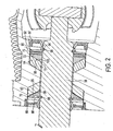
- Figure 2 more clearly shows these play reducing members 70 and 72.
- Play reducing member 72 can also be referred to a first wedge-shaped member or a first play reducing member.
- Play reducing member 70 can also be referred to as a second wedge-shaped member or a second play reducing member.
- Figure 7 illustrates that play reducing member 72 is a split ring separated by a split 84 extending radially with respect to the stub shaft 38.
- play reducing member 70 is fixed along stub shaft 38 by a snap ring 86 received in annular groove 88 on the shaft so as to prevent movement of the play reducing member away from the bearing 62.
- the snap ring 86 can be referred to as a first stop.
- Play reducing member 72 has its thin end or first end 73 biased towards the bearing 64 by a spring comprising a pair of spring washers 90 and 92 which extend about the shaft.
- the spring washers 90 and 92 are resilient, and can be referred to as a first resilient member.
- the spring washers 90 and 92 are compressed together between the play reducing member 72 and a snap ring 94 received in annular groove 96 on the shaft 38, thus biasing play reducing member 72 towards the bearing 64.
- the snap ring 94 can be referred to as a second stop.
- the spring washers 90 and 92 have their concave sides facing each other, but someone skilled in the art will appreciate that the spring washers 90 and 92 could equally have their concave sides on opposite sides of each other.
- the play reducing member 72 has a second end 75 and is inclined towards the shaft from the second end towards the first end 73. There are seals 97 and 99 extending about the stub portion 38 of the steering shaft and the housing 26 on each side of the assembly just described including the bearings, the play reducing members and the snap rings.
- Play reducing member 70 has an inclined surface 96 which opposes inclined surface 95 of bearing 62.
- play reducing member 72 has an inclined surface 100 which opposes inclined surface 98 of bearing 64.
- the surfaces have first and second ends corresponding to the first and second ends of the play reducing member.
- the nut 150 could act alone to press the play reducing member 72.4 towards the bearing 64.4. Fine adjustments of the nut 150 could eliminate the need for spring washers 90.4 and 92.4.
- Figure 6 shows a variation where like parts have like numbers with the additional designation ".6".
- the bearing 62.6 is a ball bearing instead of a tapered needle bearing, and the play reducing member 70.6 presses against ball bearing 62.6.
- Figure 9 shows a variation where like parts have like numbers with the additional designation ".9".
- an outer, annular shim 116 extending about the stub shaft 38.9 act to press the play reducing member 70.9 towards the bearing 62.9.
- the outer shim 116 act as a form of macro adjustment to ensure that the spring washers 90.9 and 92.9 can act as a springs within their limited displacement range and perform a micro-adjustment function. Less demanding machining requirements are needed, as the outer shim 116 act to compensate for any such variations. It will be appreciated by those skilled in the art that one or more shims can be used.
- FIG 10A and 10B show a variation where like parts have like numbers with the additional designation ".10".
- a crushable member 110 extends about the stub shaft 38.10 to press the play reducing member 72.10 towards the bearing 64.10.
- the crushable member 110 could consist of such things as a porous material, a corrugated material (not shown) or a washer with protrusions which yield upon compression (not shown).
- the crushable member 110 acts to replace the need for spring washers.
- the crushable member yields to a certain pre-defined force.
- the crushable member has an uncrushed width 112 and an crushed width 114. During assembly, the crushable member is crushed to a desired crush width 114.
- the crushed width corresponds to the distance between play reducing member 72.10 and snap ring 94.10 when in its annular groove 96.10. In its crushed state, the crushable member 110 acts to press the play reducing member 72.10 towards the bearing 64.10.
- the crushable member 110 can act as a form of macro adjustment in association with spring washers to ensure that the spring washers (not shown) can continue to act as a springs within their limited displacement range and perform a micro-adjustment function.
- This embodiment requires less demanding machining requirements, as the crushable member 110 acts to compensate for any such variations.
- Figure 11 shows a variation where like parts have like numbers with the additional designation ".11".
- spring washers 172 and 174 are located between the second play reducing member 70.11 and outer shim 170.
- the outer shim 170 acts as a form of macro adjustment to ensure that the spring washers 172 and 174 can act as a springs within their limited displacement range and perform a micro-adjustment function. Less demanding machining requirements are needed, as the outer shim 170 acts to compensate for any such variations.
- the spring washers 172 and 174 can be referred to as an example of a second resilient member.
- the snap ring 86.11 acts as a backstop, and the outer shim 170 and spring washers 172 and 174, respectively, press the second play reducing member 70.11 towards the bearing 62.11.
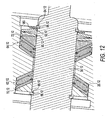
- Figure 12 shows a variation where like parts have like numbers with the additional designation ".12". This example is similar to Figure 11 , except spring washers 90.12 and 92.12 are located between the first play reducing member 72.12 and inner shim 180.
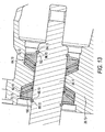
- Figure 13 shows a variation where like parts have like numbers with the additional designation ".13".
- This embodiment has a spring washer 192 between the first play reducing member 72.13 and the snap ring 94.13, and a second spring washer 190 between the second play reducing member 70.13 and the snap ring 86.13.
- a further variation on this embodiment, though not shown, includes a pair of spring washers between each of the said play reducing members and said snap rings.
- a further variation on this embodiment incorporates the outer shim as in Figure 11 , the inner shim as in Figure 12 , or a combination of outer and inner shims.
- FIG. 14 Another variation on the invention is shown in Figure 14 where like parts have like numbers with the additional designation ".14".
- Bearing rollers 200 and 202 are enclosed between the housing 26.14 and play reducing members 70.14 and 72.14. It will be appreciated by those skilled in the art that the bearing rollers could be balls.
- Play reducing members 70.14 and 72.14 have inclined surfaces 95.14 and 98.14, respectively, which are shaped to function as first bearing races. These eliminate the need for first bearing races as exemplified by first bearing race 67 of previous embodiments of the invention.
- the housing 26.14 has inclined surfaces 210 and 212, respectively, which are shaped to function as second bearing races. These eliminate the need for second bearing races as exemplified by second bearing race 69 of previous embodiments of the invention.
- This embodiment provides the advantage of an even further reduction in play as felt in the steering shaft by reducing the number of contacting parts between the stub shaft, the play reducing members, the rollers, and the housing. This reduction in contacting parts results in a reduction in the amount of compounding of machine error, and hence play.
Landscapes
- Engineering & Computer Science (AREA)
- General Engineering & Computer Science (AREA)
- Mechanical Engineering (AREA)
- Chemical & Material Sciences (AREA)
- Combustion & Propulsion (AREA)
- Transportation (AREA)
- Steering Controls (AREA)
- Support Of The Bearing (AREA)
- Rolling Contact Bearings (AREA)
- Sliding-Contact Bearings (AREA)
Description
-
EP-A-0893326 , upon which the preamble of claim 1 is based, discloses a steering column assembly including two bearing seats for angular contact bearings each bearing seat being tapered so that the diameter of a bore of a housing for the bearings tapers radially inwardly and a third bearing seat associated with a column shaft is also tapered to seat one of two inner rings of the respective bearings, which are pre-loaded and axially aligned with the bearing seats. The designs disclosed reduce the rotational effort and torque variation of the system and facilitate assembly. The mating tapers give the bearings freedom to self-align and thereby avoid common "clicking" noise. - Traditionally, marine tilt steering mechanisms have used a bushing style bearing to support the steering shaft in shaft housings. As an example of this arrangement, see United States Patent
4,941,766 to Carlson . While bushings may be sufficient for some applications, they may not be ideal in a marine steering context. This is because boats do not have a long steering column as would be found in a tractor or car. A longer steering column allows the contact points of the bushing bearing to be spaced apart a significant distance. Because the contact points can be spaced further apart compared to a marine system, there can be some radial clearance in the bearings without having noticeable movement (play) in the steering wheel. - Functionally, bushings require some clearance or they will not allow motion between the turning and stationary components. There will always be some wear in a bushing which further increase clearances. Because in a boat the entire tilting action must take place in front of the dash without moving the steering wheel too close to the driver, the steering shaft support area is very short - generally around one inch. Given the clearances that exist and the short distance between the support points relative to the distance to the outside of the steering wheel, these clearances may result in undesirable movement at the outer edges of the steering wheel.
- One of the inventors' solutions to this problem involves the use a preloaded angular contact needle bearing. The preload reduces any clearance in the radial or axial directions under reasonable loads. Play is further reduced through the use of a wedge-shaped member which engages the bearing when under load. This acts to significantly take up play between the bearing and the shaft, and play within the bearing.
- According to an aspect of the present invention, there is provided a steering apparatus for a vehicle, including a housing, a steering shaft having a longitudinal axis, a first bearing interposed between the shaft and the housing, permitting rotation of the steering shaft about the axis, a first wedge-shaped member having a thin end against the first bearing, and a means for biasing the first wedge-shaped member against the first bearing to take up play between the shaft and first bearing, and play within the first bearing, characterized in that a bracket pivotally connects to the housing to provide a tilt steering apparatus, said bracket having means for mounting on the vehicle, and the shaft having a tiltable portion rotatably mounted on the housing.
- Advantageously, the first wedge-shaped member has a surface inclined with respect to the axis and which tightly engages the bearing.
- Preferably, the steering apparatus is a steering apparatus for a marine craft.
- Referring to the drawings:
-
Figure 1 is a sectional view of a tilt steering mechanism according to an embodiment of the invention. -
Figure 2 is an enlarged sectional view thereof showing in greater detail the area of the steeringshaft being supported within a housing, with the bearings being tapered needle bearings supported by play reducing members. -
Figure 3 is a view similar toFigure 2 of a variation where one of the play reducing members is formed integrally with the stub shaft. -
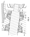
Figure 4 is a view similar toFigure 2 of an alternative embodiment of the invention using a nut threadedly engaging a threaded portion of the stub shaft and pressing spring washers towards the bearings. -
Figure 5A and 5B are enlarged, fragmentary sectional views showing in greater detail a fragment of a typical bearing and the associated play that is possible between adjacent elements,Figure 5A showing play prior to reduction thereof andFigure 5B after reduction according to the invention. -
Figure 6 is an enlarged, fragmentary sectional view of an alternative embodiment where the bearing is a ball bearing. -
Figure 7 is a sectional view, taken along line 7 - 7 ofFigure 1 , showing the steering shaft and the play reducing member. -
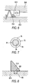
Figure 8 is an enlarged fragmentary view of an alternative embodiment of the invention which shows an o-ring in an annular groove of the stub shaft and between the stub shaft and the play reducing member. -
Figure 9 is a view similar toFigure 2 of an alternative embodiment of the invention using an outer shim which extends around the stub shaft and press the play reducing member towards the bearing. -
Figure 10A and 10B are enlarged fragmentary views of an alternative embodiment of the invention which shows a crushable member which fits between the play reducing member and a snap ring, and presses the play reducing member towards the bearing,Figure 10A showing the crushable member prior to crushing andFigure 10B after crushing. -
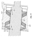
Figure 11 is an enlarged sectional view of an alternative embodiment of the invention where spring washers are located between the second play reducing member and the outer shim, pressing the second play reducing member towards the bearing. -
Figure 12 is a view similar toFigure 11 of an alternative embodiment of the invention where spring washers are located between the first play reducing member and inner shim, pressing the first play reducing member towards the bearing. -
Figure 13 is an enlarged sectional view of an alternative embodiment of the invention where a spring washer is located between the first play reducing member and adjacent snap ring, and another spring washer is located between the second play reducing member and adjacent snap ring. -
Figure 14 is a view similar toFigure 1 of an alternative embodiment of the invention where the housing and play reducing members act as races for the bearing rollers. - Referring to the drawings and first to
Figure 1 , a tilt steering mechanism is shown generally at 20. The mechanism is suitable for use with boats or other vehicles such as automobiles. The mechanism includes ahousing 26, capable of vertical tilting as described below, and abracket 24, which is stationary and typically mounted to the dashboard of the vehicle. The steering mechanism is generally similar to that disclosed in United States Patent4,941,766 to Carlson . - It will be appreciated by those skilled in the art that the apparatus could connect to helm pumps, electrical devices, or other such steering devices in a variety of ways. Connection means for the tilt steering mechanism include the use of a potentiometer for detecting changes in motion of a steering shaft or the use of electrical sensors for detecting changes in motion of a steering shaft. Additionally, another style of U-joint could be used other than the one presented below.
- In this example, the apparatus includes a
socket member 30 having arectangular recess 32 at one end for receiving a main portion of a steering shaft (not shown) which is connected to the steering gear of the vehicle. As stated above, this could be a helm pump for a marine hydraulic steering system. A pin is received inaperture 34 such that the main portion of the steering shaft rotates with thesocket member 30. The socket member includes asocket 36 which is partially circular when viewed from the side as shown inFigure 1 . The apparatus includes a stub shaft ortiltable portion 38 of the steering shaft to which a steering wheel (not shown) is connected bynut 40 andkey 42. The stub shaft has aninner end 44 with anaperture 46 receiving apin 48. A pair ofcap members 50 is received within thesocket 36. Each has acylindrical socket 52 receiving one end of thepin 48. Each of thecap members 50 has a convexly curvedouter side 56 rotatably received within thesocket 36 of thesocket member 30. - Each of the cap members has opposing flat faces (not shown) extending from the
outer side 56 towards the other cap member. These faces are vertical in the position shown inFigure 1 . These flat faces engage corresponding flat faces within thesocket 36 of thesocket member 30. Accordingly it may be seen that thestub shaft 38 can tilt vertically, but side to side motion is prevented. - The
housing 26 can be tilted to a desired position by manually pivotinglever 27 about pin 29 and thereby disengagingtooth 31 from one of the plurality ofslots 33 and releasing thepivoting lever 27 when thehousing 26, and accordingly the steering wheel, are at the desired angle and vertical position. Acoil spring 35 is stretched between thehousing 26 and thebracket 24, thus biasing thehousing 26 and the steering wheel to a raised position. Thehousing 26 has acavity 60 which rotatably receivesstub shaft 38. Thehousing 26 acts as a support member for thestub shaft 38. In a more conventional unit of this type, such as disclosed in United States Patent4,941,766 , the stub shaft is rotatably supported in the housing by a simple bushing. For many applications this is sufficient. However a relatively small amount of play between the bushing, the housing and the shaft results in an exaggerated amount of play at the rim of the steering wheel connected to the shaft. The amount of play in the bearing is exaggerated by the diameter of the steering wheel. This amount of play may be unacceptable or undesirable for some applications, particularly for high-quality steering systems. - In this embodiment, a pair of
bearings enlarged portions cavity 60. These bearings rotatably support the stub shaft within thehousing 26. Such bearings are advantageous because they provide axial support for the stub portion of the steering shaft as well as radial support, that is support perpendicular to the shaft, within thehousing 26. However, undesirable play may still occur between the shaft and the bearings and within the bearings. - As shown in
Figure 5A , thebearing 64 has a plurality of circumferentially space-apartrollers 65 rotatably received between afirst race 67 of the bearing and asecond race 69. Play is possible between a number of adjacent elements as shown diagrammatically inFigure 5A byplay 71 between the bearing 64 and thestub shaft 38, and play. 77 between the roller and theraces Figure 5B , theplay reducing member 72 effectively takes up space and effectively sandwiches thebearing 64 between theplay reducing member 72 andhousing 26. Similarly, theplay reducing member 72 is sandwiched between the bearing 64 and thestub shaft 38. - The embodiment of
Figure 1 has a pair of play reducing members, in this case annular wedge-shapedmembers stub shaft 38.Figure 2 more clearly shows theseplay reducing members member 72 can also be referred to a first wedge-shaped member or a first play reducing member. Play reducingmember 70 can also be referred to as a second wedge-shaped member or a second play reducing member. -
Figure 7 illustrates thatplay reducing member 72 is a split ring separated by asplit 84 extending radially with respect to thestub shaft 38. - Referring to
Figure 2 , play reducingmember 70 is fixed alongstub shaft 38 by asnap ring 86 received inannular groove 88 on the shaft so as to prevent movement of the play reducing member away from thebearing 62. Thesnap ring 86 can be referred to as a first stop. Play reducingmember 72 has its thin end orfirst end 73 biased towards the bearing 64 by a spring comprising a pair ofspring washers play reducing member 72 and asnap ring 94 received inannular groove 96 on theshaft 38, thus biasingplay reducing member 72 towards the bearing 64. Thesnap ring 94 can be referred to as a second stop. In this example, thespring washers spring washers play reducing member 72 has asecond end 75 and is inclined towards the shaft from the second end towards thefirst end 73. There areseals stub portion 38 of the steering shaft and thehousing 26 on each side of the assembly just described including the bearings, the play reducing members and the snap rings. - Play reducing
member 70 has aninclined surface 96 which opposes inclinedsurface 95 ofbearing 62. Likewise play reducingmember 72 has aninclined surface 100 which opposes inclinedsurface 98 ofbearing 64. The surfaces have first and second ends corresponding to the first and second ends of the play reducing member. - When the
play reducing member 72 is forced to the left, from the point of view ofFigures 5A and 5B , towards bearing 64, theplay reducing member 72 collapses around thestub shaft 38 as thesplit 84 of theplay reducing member 72, shown inFigure 7 , is reduced in size, and also mates with and tightly engages thebearing 64. This takes up the play between the various components shownFigure 5A since thebearing 64 is forced away from theshaft 38, towardshousing 26 and the two races of the bearing,first race 67 andsecond race 69, are forced together with the spaced-apartrollers 65 in between. This reduces or eliminates perceptible play at the rim of the steering wheel. - A number of variations of the invention are possible. Referring to
Figure 3 , this shows a variation generally similar to the previous embodiment and like parts have like numbers with the additional designation ".3". In this example the play reducing member 70.3 is formed integrally with stub shaft 38.3. - Referring to
Figure 4 , like parts have like numbers with the additional designation ".4". In this example, instead ofsnap ring 94, there is anut 150 threadedly engaging a threadedportion 152 of stub shaft 38.4 to press the spring washers 90.4 and 92.4 towards the bearing 64.4. Thenut 150 acts as a form of macro adjustment to ensure that the spring washers 90.4 and 92.4 can act as a springs within their limited displacement range and perform a micro-adjustment function. Less demanding machining requirements are needed compared to previous embodiments, as thenut 150 acts to compensate for any such variations. - In an alternative embodiment not shown, the
nut 150 could act alone to press the play reducing member 72.4 towards the bearing 64.4. Fine adjustments of thenut 150 could eliminate the need for spring washers 90.4 and 92.4. -
Figure 6 shows a variation where like parts have like numbers with the additional designation ".6". In this example the bearing 62.6 is a ball bearing instead of a tapered needle bearing, and the play reducing member 70.6 presses against ball bearing 62.6. - In the embodiment of
Figure 8 , where like parts have like numbers with the additional designation ".8", there is an o-ring 160 in anannular groove 162 of the stub shaft 38.8 and between the stub shaft 38.8 and the play reducing member 72.8. The play reducing members as exemplified by play reducing member 72.8, are whole - not containing a split. Play reducing member 72.8 presses up snugly against the tapered needle bearing (not shown) and the stub shaft 38.8 over o-ring 160. This embodiment removes the need for the play reducing members to be split. This is because o-ring 160 is compressed, and the associated reactive force thereby holds the play reducing member 72.8 centered on the stub shaft 38.8. This embodiment provides a more even force which keeps the play reducing member 72.8 and stub shaft 38.8 connected to each other. -
Figure 9 shows a variation where like parts have like numbers with the additional designation ".9". In this example, an outer,annular shim 116 extending about the stub shaft 38.9 act to press the play reducing member 70.9 towards the bearing 62.9. Theouter shim 116 act as a form of macro adjustment to ensure that the spring washers 90.9 and 92.9 can act as a springs within their limited displacement range and perform a micro-adjustment function. Less demanding machining requirements are needed, as theouter shim 116 act to compensate for any such variations. It will be appreciated by those skilled in the art that one or more shims can be used. -
Figure 10A and 10B show a variation where like parts have like numbers with the additional designation ".10". In this example, acrushable member 110 extends about the stub shaft 38.10 to press the play reducing member 72.10 towards the bearing 64.10. Thecrushable member 110 could consist of such things as a porous material, a corrugated material (not shown) or a washer with protrusions which yield upon compression (not shown). In this example, thecrushable member 110 acts to replace the need for spring washers. The crushable member yields to a certain pre-defined force. The crushable member has anuncrushed width 112 and an crushedwidth 114. During assembly, the crushable member is crushed to a desiredcrush width 114. The crushed width corresponds to the distance between play reducing member 72.10 and snap ring 94.10 when in its annular groove 96.10. In its crushed state, thecrushable member 110 acts to press the play reducing member 72.10 towards the bearing 64.10. - Alternatively, the
crushable member 110. can act as a form of macro adjustment in association with spring washers to ensure that the spring washers (not shown) can continue to act as a springs within their limited displacement range and perform a micro-adjustment function. This embodiment requires less demanding machining requirements, as thecrushable member 110 acts to compensate for any such variations. -
Figure 11 shows a variation where like parts have like numbers with the additional designation ".11". In this example,spring washers outer shim 170. As was similarly mentioned above in an alternative embodiment, theouter shim 170 acts as a form of macro adjustment to ensure that thespring washers outer shim 170 acts to compensate for any such variations. Thespring washers outer shim 170 andspring washers -
Figure 12 shows a variation where like parts have like numbers with the additional designation ".12". This example is similar toFigure 11 , except spring washers 90.12 and 92.12 are located between the first play reducing member 72.12 andinner shim 180. -
Figure 13 shows a variation where like parts have like numbers with the additional designation ".13". This embodiment has aspring washer 192 between the first play reducing member 72.13 and the snap ring 94.13, and asecond spring washer 190 between the second play reducing member 70.13 and the snap ring 86.13. A further variation on this embodiment, though not shown, includes a pair of spring washers between each of the said play reducing members and said snap rings. Additionally, a further variation on this embodiment, though not shown, incorporates the outer shim as inFigure 11 , the inner shim as inFigure 12 , or a combination of outer and inner shims. - Another variation on the invention is shown in
Figure 14 where like parts have like numbers with the additional designation ".14". In this example, bearing races per se are not used nor needed.Bearing rollers first bearing race 67 of previous embodiments of the invention. Similarly, the housing 26.14 has inclinedsurfaces second bearing race 69 of previous embodiments of the invention. - This embodiment provides the advantage of an even further reduction in play as felt in the steering shaft by reducing the number of contacting parts between the stub shaft, the play reducing members, the rollers, and the housing. This reduction in contacting parts results in a reduction in the amount of compounding of machine error, and hence play.
- It will be understood by someone skilled in the art that many of the details provided above are by way of example only and are not intended to limit the scope of the invention which is to be determined with reference to the following claims.
Claims (29)
- A steering apparatus (20) for a vehicle, including a housing (26), a steering shaft having a longitudinal axis, a first bearing (64) interposed between the shaft and the housing (26), permitting rotation of the steering shaft about the axis, a first wedge-shaped member (72) having a thin end (73) against the first bearing (64), and a means for biasing the first wedge-shaped member (72) against the first bearing (64) to take up play between the shaft and first bearing (64), and play within the first bearing (64), characterized in that a bracket (24) pivotably connects to the housing (26) to provide a tilt steering apparatus, said bracket (24) having means for mounting on the vehicle, and the shaft having a tiltable portion (38) rotatably mounted on the housing (26).
- The steering apparatus (20) of claim 1, wherein the first wedge-shaped member (72) is annular.
- The steering apparatus (20) of claim 1 or 2, wherein the first wedge-shaped member (72) is split.
- The steering apparatus (20) of claim 1 or 2, wherein an o-ring (160) is located in an annular groove (162) of the shaft and between the shaft and the first wedge-shaped member (72.8).
- The steering apparatus (20) of any preceding claim, wherein the means for biasing the first wedge-shaped member (72) includes a first resilient member (90, 92) extending about the shaft on the side of the first wedge-shaped member (72) opposite the first bearing (64).
- The steering apparatus (20) of claim 5, wherein the first resilient member (90, 92) is a spring.
- The steering apparatus (20) of any preceding claim, wherein the means for biasing the first wedge-shaped member (72.4) includes a nut (150) extending about the shaft on a side of the first wedge-shaped member (72.4) opposite the first bearing (64.4).
- The steering apparatus (20) of any one of claims 1 to 3, or claims 5 or 6 as appended to claims 1 to 3, wherein the means for biasing (90, 92) the first wedge-shaped member (72) further includes a snap ring (94) extending about the shaft on a side of the first wedge-shaped member (72) opposite the first bearing (64).
- The steering apparatus (20) of any one of claims 1 to 3, or claims 5, 6 or 8 as appended to claims 1 to 3, wherein the means for biasing the first wedge-shaped member (72.10) includes a crushable member (110) extending about the shaft on a side of the first wedge-shaped member (72.10) opposite the first bearing (64.10).
- The steering apparatus (20) of claim 9, wherein the crushable member (110) yields to a certain pre-defined force.
- The steering apparatus (20) of claim 9 or 10, wherein the crushable member (110) is of a corrugated material.
- The steering apparatus (20) of any one of claims 9 to 11, wherein the crushable member (110) is of a porous material.
- The steering apparatus (20) of any one of claims 9 to 12, wherein the crushable member (110) is a washer with protrusions which yield upon compression.
- The steering apparatus (20) of claim 8, wherein an inner shim (180) extends about the shaft on the side of the first wedge-shaped member (72.12) opposite the first bearing (64.12), said inner shim (180) arranged to press the first wedge-shaped member (72.12) towards the first bearing (64.12).
- The steering apparatus (20) of any preceding claim, and further including a second bearing (62) spaced-apart along the shaft from the first bearing (64), a second wedge-shaped member (70) having a thin end against the second bearing (62).
- The steering apparatus (20) of claim 15, wherein the second wedge-shaped member (70.3) is integral with the shaft.
- The steering apparatus (20) of claim 15 or 16, and further including a second resilient member extending about the shaft on the side of the second wedge-shaped member (70) opposite the second bearing (62).
- The steering apparatus (20) of claim 17, wherein the first resilient member is a spring and the second resilient member is a spring.
- The steering apparatus (20) of claim 17 or 18, wherein the first resilient member is formed by a spring washer (192) extending about the shaft, and the second resilient member is formed by a spring washer (190) extending about the shaft.
- The steering apparatus (20) of claim 18 or 19, wherein the first resilient member is formed by a pair of spring washers (90, 92) extending about the shaft, and the second resilient member is formed by a pair of spring washers (172, 174) extending about the shaft.
- The steering apparatus (20) of claim 15 as appended to claim 4, and further including a second o-ring located in an annular groove of the shaft and between the shaft and the second wedge-shaped member (70).
- The steering apparatus (20) of any one of claims 15 to 20, wherein an outer shim (170) extends about the shaft on a side of the second wedge-shaped member (70) opposite the second bearing (62), said outer shim (170) arranged to press the second wedge-shaped member (70) towards the second bearing (62).
- The steering apparatus (20) of any one of claims 15 to 22, including a first stop (86) on a side of the second wedge-shaped member (70) opposite the second bearing (62) which prevents movement of the second wedge-shaped member (70) away from the second bearing (62).
- The steering apparatus (20) of any one of claims 9 to 23 as appended to claim 8 as appended to claim 6, and further including a second stop being said snap ring (94) on a side of the spring opposite the first wedge-shaped member (72) which prevents movement of the spring away from the first wedge-shaped member (72).
- The steering apparatus (20) of any one of claims 15 to 24, wherein the or each bearing (64, 62) is a tapered needle bearing.
- The steering apparatus (20) as claimed in any one of claims 15 to 25, wherein the or each bearing comprises a roller (65, 200, 202).
- The steering apparatus (20) as claimed in claim 26, wherein the or each of the bearings (64, 62) comprises a pair of races (67, 69) disposed on respective opposite sides of the or each roller (65), the or each said wedge-shaped member (72, 70) being disposed between the shaft and one of the pair of races (67, 69).
- The steering apparatus (20) as claimed in any preceding claim, the housing (26) being tiltable so the steering shaft can be vertically adjusted.
- The steering apparatus (20) as claimed in any one of claims 15 to 24, wherein the or each bearing (64, 62) is a ball bearing.
Applications Claiming Priority (1)
| Application Number | Priority Date | Filing Date | Title |
|---|---|---|---|
| US11/444,534 US7717462B2 (en) | 2006-06-01 | 2006-06-01 | Tilt steering mechanism |
Publications (2)
| Publication Number | Publication Date |
|---|---|
| EP1862370A1 EP1862370A1 (en) | 2007-12-05 |
| EP1862370B1 true EP1862370B1 (en) | 2010-04-07 |
Family
ID=38325197
Family Applications (1)
| Application Number | Title | Priority Date | Filing Date |
|---|---|---|---|
| EP06124092A Active EP1862370B1 (en) | 2006-06-01 | 2006-11-14 | Tilt steering mechanism |
Country Status (5)
| Country | Link |
|---|---|
| US (1) | US7717462B2 (en) |
| EP (1) | EP1862370B1 (en) |
| JP (1) | JP5356644B2 (en) |
| AU (1) | AU2006233213B2 (en) |
| DE (1) | DE602006013433D1 (en) |
Families Citing this family (10)
| Publication number | Priority date | Publication date | Assignee | Title |
|---|---|---|---|---|
| DE102004045876B4 (en) * | 2004-09-20 | 2006-07-06 | Delphi Technologies, Inc., Troy | Fastening device for a steering column module of a motor vehicle |
| US20150056001A1 (en) * | 2013-08-22 | 2015-02-26 | Powers and Sons, LLC | Mechanical overload fuse for steering linkage |
| JP6333191B2 (en) * | 2015-02-13 | 2018-05-30 | 本田技研工業株式会社 | Tilt steering device |
| DE102016114678A1 (en) * | 2016-08-08 | 2018-02-08 | Thyssenkrupp Ag | Rotary bearing arrangement for a steering column of a motor vehicle |
| WO2018088228A1 (en) * | 2016-11-11 | 2018-05-17 | Ntn株式会社 | Method for designing thrust needle bearing, thrust needle bearing, and method for manufacturing thrust needle bearing |
| JP7203327B2 (en) * | 2020-07-30 | 2023-01-13 | 日本発條株式会社 | helm device |
| US12326735B2 (en) | 2021-07-23 | 2025-06-10 | Seakeeper, Inc. | Dynamic active control system with engine control |
| US12214850B2 (en) | 2021-08-19 | 2025-02-04 | Seakeeper, Inc. | Commissioning strategy |
| US12485998B2 (en) | 2021-08-23 | 2025-12-02 | Seakeeper, Inc. | Mounting plate assembly and system |
| AU2023312810A1 (en) | 2022-07-29 | 2025-02-13 | Seakeeper, Inc. | Distribution module |
Family Cites Families (18)
| Publication number | Priority date | Publication date | Assignee | Title |
|---|---|---|---|---|
| US2509587A (en) | 1945-09-14 | 1950-05-30 | Ross Gear & Tool Co | Steering post bearing |
| JPS4837823A (en) * | 1971-09-21 | 1973-06-04 | ||
| US3807819A (en) * | 1972-08-04 | 1974-04-30 | Borg Warner | Bearing assembly |
| US4941766A (en) | 1986-12-19 | 1990-07-17 | Teleflex Incorporated | Tilt wheel universal |
| US5826987A (en) * | 1987-04-04 | 1998-10-27 | The Torrington Company | Mounting of a shaft within a housing |
| US4850239A (en) | 1988-01-29 | 1989-07-25 | General Motors Corporation | Steering wheel hub and upper steering shaft assembly for tilt head steering columns |
| US5222817A (en) * | 1991-04-22 | 1993-06-29 | Glazier Stephen C | Prestressed roller bearing |
| US5538282A (en) * | 1994-10-03 | 1996-07-23 | Chrysler Corporation | Steering column assembly |
| US5724907A (en) * | 1996-07-23 | 1998-03-10 | Teleflex Incorporated | Watercraft steering mounted accessory control assembly |
| JP3904286B2 (en) * | 1996-11-29 | 2007-04-11 | ヤマハ発動機株式会社 | Steering device for small boat |
| FR2756885B1 (en) * | 1996-12-09 | 1999-01-15 | Skf France | STEERING COLUMN BEARING FOR MOTOR VEHICLES |
| FR2760496B1 (en) * | 1997-03-05 | 1999-05-21 | Nadella | ARRANGEMENT OF A TREE IN A SUPPORT |
| US5829891A (en) | 1997-07-22 | 1998-11-03 | The Torrington Company | Mounting for steering column |
| US6227715B1 (en) | 1998-12-09 | 2001-05-08 | INA Wälzlager Schaeffler oHG | Rolling bearing assembly for support of a steering shaft |
| DE19952119A1 (en) * | 1999-10-29 | 2001-05-03 | Schaeffler Waelzlager Ohg | Angular ball bearing for car steering shaft has flexible plastic tolerance ring between inner ring and shaft, mounting between shaft and ring having retaining components with claws which fit over outer ring |
| DE19955643A1 (en) * | 1999-11-19 | 2001-05-23 | Schaeffler Waelzlager Ohg | Angular ball bearing for car steering column has flexible tolerance ring made of polymer fitted to its inner ring by projections which grip it, outer ring having one contact point with each ball and inner ring having two |
| US6612198B2 (en) * | 2001-11-01 | 2003-09-02 | Delphi Technologies, Inc. | Lash-free cable drive |
| US7302979B2 (en) * | 2005-03-16 | 2007-12-04 | Dana Corporation | Vehicle tire inflation system and sensor and method of use |
-
2006
- 2006-06-01 US US11/444,534 patent/US7717462B2/en active Active
- 2006-10-27 AU AU2006233213A patent/AU2006233213B2/en active Active
- 2006-11-14 EP EP06124092A patent/EP1862370B1/en active Active
- 2006-11-14 DE DE602006013433T patent/DE602006013433D1/en active Active
- 2006-11-24 JP JP2006316584A patent/JP5356644B2/en active Active
Also Published As
| Publication number | Publication date |
|---|---|
| US20070278777A1 (en) | 2007-12-06 |
| EP1862370A1 (en) | 2007-12-05 |
| DE602006013433D1 (en) | 2010-05-20 |
| JP2007320549A (en) | 2007-12-13 |
| JP5356644B2 (en) | 2013-12-04 |
| AU2006233213B2 (en) | 2012-06-14 |
| US7717462B2 (en) | 2010-05-18 |
| AU2006233213A1 (en) | 2007-12-20 |
Similar Documents
| Publication | Publication Date | Title |
|---|---|---|
| EP1884446B1 (en) | Steering apparatus equipped with ring type support yoke | |
| US9102351B2 (en) | Electronic power-steering apparatus | |
| JP3015202B2 (en) | Bearing assembly | |
| US20040222036A1 (en) | Electric servo-assisted steering system for motor vehicles | |
| US7717462B2 (en) | Tilt steering mechanism | |
| EP3299253B1 (en) | Steering device of vehicle | |
| US20130036845A1 (en) | Rack and pinion steering gear unit | |
| EP0934863B1 (en) | Rack and pinion steering device with split roller rack bar support | |
| EP0893326B1 (en) | Mounting for steering column | |
| US9738305B2 (en) | Tilt steering apparatus | |
| US6357314B1 (en) | Rack-and-pinion steering gear | |
| JP2019536686A (en) | Steering transmission and steering system | |
| JP2008120213A (en) | Vehicle steering system | |
| CN105324290B (en) | The apparatus for adjusting position of steering wheel | |
| US20180003291A1 (en) | Gear unit for motor vehicle | |
| JP2007099260A (en) | Steering device | |
| US20190162236A1 (en) | Steering Gear Bearing Arrangement | |
| JP2007203947A (en) | Worm speed reducer for electric power steering device and electric power steering device incorporating the same | |
| JP4622638B2 (en) | Rack and pinion type steering gear | |
| CN112969861B (en) | Steering system swing bearing | |
| CN112196906A (en) | Noise-optimized bearing units for power steering | |
| US11873038B2 (en) | Electromechanical power steering system having a pivot-pendulum bearing assembly | |
| EP3750782B1 (en) | Improved rocker/lever arm assembly for a steering system of a vehicle | |
| JP5471354B2 (en) | Steering device | |
| US20240116558A1 (en) | Steer-by-wire road wheel actuator ball screw anti-rotation mechanism |
Legal Events
| Date | Code | Title | Description |
|---|---|---|---|
| PUAI | Public reference made under article 153(3) epc to a published international application that has entered the european phase |
Free format text: ORIGINAL CODE: 0009012 |
|
| AK | Designated contracting states |
Kind code of ref document: A1 Designated state(s): AT BE BG CH CY CZ DE DK EE ES FI FR GB GR HU IE IS IT LI LT LU LV MC NL PL PT RO SE SI SK TR |
|
| AX | Request for extension of the european patent |
Extension state: AL BA HR MK YU |
|
| 17P | Request for examination filed |
Effective date: 20080512 |
|
| 17Q | First examination report despatched |
Effective date: 20080612 |
|
| AKX | Designation fees paid |
Designated state(s): DE GB IT |
|
| GRAP | Despatch of communication of intention to grant a patent |
Free format text: ORIGINAL CODE: EPIDOSNIGR1 |
|
| GRAS | Grant fee paid |
Free format text: ORIGINAL CODE: EPIDOSNIGR3 |
|
| GRAA | (expected) grant |
Free format text: ORIGINAL CODE: 0009210 |
|
| AK | Designated contracting states |
Kind code of ref document: B1 Designated state(s): DE GB IT |
|
| REG | Reference to a national code |
Ref country code: GB Ref legal event code: FG4D |
|
| REF | Corresponds to: |
Ref document number: 602006013433 Country of ref document: DE Date of ref document: 20100520 Kind code of ref document: P |
|
| PLBE | No opposition filed within time limit |
Free format text: ORIGINAL CODE: 0009261 |
|
| STAA | Information on the status of an ep patent application or granted ep patent |
Free format text: STATUS: NO OPPOSITION FILED WITHIN TIME LIMIT |
|
| 26N | No opposition filed |
Effective date: 20110110 |
|
| REG | Reference to a national code |
Ref country code: DE Ref legal event code: R119 Ref document number: 602006013433 Country of ref document: DE Effective date: 20140603 |
|
| PG25 | Lapsed in a contracting state [announced via postgrant information from national office to epo] |
Ref country code: DE Free format text: LAPSE BECAUSE OF NON-PAYMENT OF DUE FEES Effective date: 20140603 |
|
| REG | Reference to a national code |
Ref country code: DE Ref legal event code: R073 Ref document number: 602006013433 Country of ref document: DE |
|
| REG | Reference to a national code |
Ref country code: DE Ref legal event code: R074 Ref document number: 602006013433 Country of ref document: DE |
|
| REG | Reference to a national code |
Ref country code: DE Ref legal event code: R074 Ref document number: 602006013433 Country of ref document: DE Effective date: 20141218 |
|
| PGRI | Patent reinstated in contracting state [announced from national office to epo] |
Ref country code: DE Effective date: 20141215 |
|
| REG | Reference to a national code |
Ref country code: DE Ref legal event code: R082 Ref document number: 602006013433 Country of ref document: DE Representative=s name: VON KREISLER SELTING WERNER - PARTNERSCHAFT VO, DE Ref country code: DE Ref legal event code: R081 Ref document number: 602006013433 Country of ref document: DE Owner name: MARINE CANADA ACQUISITION INC., RICHMOND, CA Free format text: FORMER OWNER: TELEFLEX CANADA INC., RICHMOND, BRITISH COLUMBIA, CA Ref country code: DE Ref legal event code: R082 Ref document number: 602006013433 Country of ref document: DE Representative=s name: DOMPATENT VON KREISLER SELTING WERNER - PARTNE, DE |
|
| P01 | Opt-out of the competence of the unified patent court (upc) registered |
Effective date: 20230526 |
|
| PGFP | Annual fee paid to national office [announced via postgrant information from national office to epo] |
Ref country code: IT Payment date: 20250915 Year of fee payment: 20 |
|
| PGFP | Annual fee paid to national office [announced via postgrant information from national office to epo] |
Ref country code: DE Payment date: 20251021 Year of fee payment: 20 |
|
| PGFP | Annual fee paid to national office [announced via postgrant information from national office to epo] |
Ref country code: GB Payment date: 20251114 Year of fee payment: 20 |