EP1862263B1 - Combustion-driven fastening tool - Google Patents
Combustion-driven fastening tool Download PDFInfo
- Publication number
- EP1862263B1 EP1862263B1 EP07108096A EP07108096A EP1862263B1 EP 1862263 B1 EP1862263 B1 EP 1862263B1 EP 07108096 A EP07108096 A EP 07108096A EP 07108096 A EP07108096 A EP 07108096A EP 1862263 B1 EP1862263 B1 EP 1862263B1
- Authority
- EP
- European Patent Office
- Prior art keywords
- circuit
- combustion
- fastening tool
- ignition
- circuits
- Prior art date
- Legal status (The legal status is an assumption and is not a legal conclusion. Google has not performed a legal analysis and makes no representation as to the accuracy of the status listed.)
- Active
Links
- 238000002485 combustion reaction Methods 0.000 title claims description 13
- 239000003380 propellant Substances 0.000 claims description 16
- 239000000446 fuel Substances 0.000 description 8
- 238000002347 injection Methods 0.000 description 6
- 239000007924 injection Substances 0.000 description 6
- 238000000926 separation method Methods 0.000 description 3
- 230000001960 triggered effect Effects 0.000 description 3
- 239000004604 Blowing Agent Substances 0.000 description 2
- 239000003990 capacitor Substances 0.000 description 2
- 239000007789 gas Substances 0.000 description 2
- 239000007788 liquid Substances 0.000 description 2
- 239000003570 air Substances 0.000 description 1
- 239000012080 ambient air Substances 0.000 description 1
- 238000010276 construction Methods 0.000 description 1
- 230000001419 dependent effect Effects 0.000 description 1
- 238000001704 evaporation Methods 0.000 description 1
- 230000008020 evaporation Effects 0.000 description 1
- 239000002737 fuel gas Substances 0.000 description 1
- 239000003915 liquefied petroleum gas Substances 0.000 description 1
- 238000004519 manufacturing process Methods 0.000 description 1
- 238000005259 measurement Methods 0.000 description 1
- 238000000034 method Methods 0.000 description 1
- 239000000203 mixture Substances 0.000 description 1
- 239000007800 oxidant agent Substances 0.000 description 1
- 230000002441 reversible effect Effects 0.000 description 1
- 239000000758 substrate Substances 0.000 description 1
Images


Classifications
-
- B—PERFORMING OPERATIONS; TRANSPORTING
- B25—HAND TOOLS; PORTABLE POWER-DRIVEN TOOLS; MANIPULATORS
- B25C—HAND-HELD NAILING OR STAPLING TOOLS; MANUALLY OPERATED PORTABLE STAPLING TOOLS
- B25C1/00—Hand-held nailing tools; Nail feeding devices
- B25C1/08—Hand-held nailing tools; Nail feeding devices operated by combustion pressure
Definitions
- the present invention relates to a combustion-driven setting tool referred to in the preamble of claim 1. Art.
- Such setting devices have a combustion chamber in which a portion of liquefied petroleum gas or another vaporizable fuel with an oxidizing agent such. B. ambient air, is combustible.
- a setting piston displaceably guided in a piston guide is driven in order to drive a fastening element into an article.
- a combustion-powered setting tool which has an electronic control with a microprocessor for controlling the ignition and the injection.
- the setting tool in this case has various sensors, inter alia, for measuring the air pressure of the environment and the fuel pressure.
- the metering and metering of the fuel from the fuel reservoir to the combustor is controlled by the microprocessor based on the data sensed by the sensors, for which purpose the microprocessor cooperates with a control valve for the fuel.
- a disadvantage of the combined ignition and injection electronics of US Pat. No. 6,123,241 is that it may cause interference by the EMC emission of the spark, which affect the whole combined electronics and so z. B. can also influence a subsequent re-fuel injection.
- the object of the present invention is to develop a setting tool of the aforementioned type, which avoids the disadvantages mentioned and ensures a low-noise workflow.
- control electronics on at least two logically separate circuits, which are electrically separable from each other and of which a first circuit controls the metering device and a second circuit, the ignition device.
- At least one of the two circuits has at least one microprocessor, whereby a fast data processing is ensured, even if a plurality of parameters is present as input values for the control.
- both the first circuit and the second circuit each have at least one microprocessor.
- first circuit and the second circuit can each be activated via at least one switching means, wherein the switching means are independent of each other. This allows the injection to occur as early as possible, so that there is sufficient time between the injection and the ignition for the evaporation of the fuel gas available.
- a single energy source for supplying both circuits with electrical energy is provided, thereby avoiding additional expenditure in the production and a small volume of construction is achieved.
- the power supply by the power source via a further switching means at the same time from the first circuit and the second circuit is separable or connectable to these.
- an electrical disconnection of the two circuits is achieved at the same time when switching off the power supply.
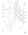
- FIGS. 1 and 2 is an inventive, operable with a liquid or gaseous fuel propellant setting device 10 with a propellant container 20 reproduced.
- the setting device 10 has a housing 11 with a handle 17 integrally formed thereon, on which there is a trigger switch 18, by means of which a setting process can be triggered.
- the setting tool 10 also has a setting network, which includes a combustion chamber 12 for combustion of an air-blowing agent mixture and a set in a piston guide 29 displaceably guided setting piston 19 and via a fastener is driven into a workpiece.
- a propellant container 20 is interchangeably arranged, which is formed in the present embodiment as a gas can and which contains a liquid gas.
- the propellant container 20 has at one end a valve outlet 23 of a valve 22, such. B. a stem, on, can be output via the propellant from the propellant container 20.
- a connection element 14 such in the propellant container receptacle 21, a connection element 14, such.
- the propellant container is then connected via a outgoing from the connection element 14 propellant conduit 15 with the combustion chamber 12, wherein in the propellant conduit 15 is still a metering device 13 is arranged, via which the propellant is influenced to the combustion chamber 12.
- the metering device 13 includes z. B. an electronically controllable valve and may be formed as a fuel injection device.
- an ignition device 16 such as, for. B. a spark plug, arranged, via which a combustion process in the combustion chamber 12 can be triggered.
- the ignition device 16 and the metering device 13 are electronically designated by a total of 30 and in FIG. 2 more precisely controlled control electronics controlled.
- the control electronics 30 has two logic circuits 33, 34 which are logically separate from one another, of which the first circuit 33 controls the metering device 13 and the second circuit 34 controls the ignition device 16.
- the first circuit 33 has a first microprocessor 37 which, on the basis of stored data and measurement data of sensor means 41, 42, which are connected to the first circuit 33, determines the necessary for a setting dose of the blowing agent and transmits the control commands to the metering device 13 ,
- the first circuit 33 is connected to the metering device 13 via a first control line 31.
- a first sensor means 41 serves to detect the ambient temperature
- a second sensor means 42 serves to detect the ambient pressure.
- a first switching means 35 is arranged, the z. B. is designed as a nose switch in the mouth region of the setting device 10. About this switching means 35, the first circuit 33 is independently activated by the second circuit 34, z. B. when the setting tool is pressed against a workpiece or a substrate.
- the second circuit 32 has a second microprocessor 38 which controls the ignition by the ignition device 16. Via a second control line 32, the second circuit 34 is connected to the ignition device 16.
- a second switching means 36 is arranged, the z. B. is coupled to the trigger switch or is formed by the trigger switch itself.
- the second circuit 34 can be activated independently of the first circuit 33, z. B. when the setting device 10 is triggered via the trigger switch 18.
- the second switching means 36 could be switched only indirectly as a result of actuation of the trigger switch 18.
- an energy source 40 such. B. one or more batteries or accumulators, provided, which is connected via leads respectively to the first circuit 33 and the second circuit 34 (see Fig. 2 ). About one Further switching means 39, the power source 40 connected to the circuits 33, 34 and these are supplied with electrical energy.
- the ignition control (34) releases the ignition caused by the discharge of at least one capacitor, the ignition control (34) causes the switch (39) to open, immediately leading to the dosing control (33) being switched off. Ignition is now completed by the energy stored in said capacitor.
Description
Die vorliegende Erfindung betrifft ein brennkraftbetriebenes Setzgerät der im Oberbegriff des Patentanspruchs 1 genannten Art.The present invention relates to a combustion-driven setting tool referred to in the preamble of
Derartige Setzgeräte weisen eine Brennkammer auf, in der eine Portion Flüssiggas oder ein anderer verdampfbarer Brennstoff mit einem Oxidationsmittel, wie z. B. Umgebungsluft, verbrennbar ist. Mittels der Verbrennungsenergie wird ein in einer Kolbenführung versetzbar geführter Setzkolben angetrieben, um ein Befestigungselement in einen Gegenstand einzutreiben.Such setting devices have a combustion chamber in which a portion of liquefied petroleum gas or another vaporizable fuel with an oxidizing agent such. B. ambient air, is combustible. By means of the combustion energy, a setting piston displaceably guided in a piston guide is driven in order to drive a fastening element into an article.
Aus der
Von Nachteil bei der kombinierten Zünd- und Einspritzelektronik der
Die Aufgabe der vorliegenden Erfindung liegt daher darin, ein Setzgerät der vorgenannten Art zu entwickeln, welches die genannten Nachteile vermeidet und einen störungsarmen Arbeitsablauf gewährleistet.The object of the present invention is to develop a setting tool of the aforementioned type, which avoids the disadvantages mentioned and ensures a low-noise workflow.
Diese Aufgabe wird erfindungsgemäss durch die im kennzeichnenden Teil von Anspruch 1 genannten Massnahmen erreicht.This object is achieved according to the invention by the measures mentioned in the characterizing part of
Demnach weist die Steuerelektronik wenigstens zwei logisch getrennte Schaltkreise auf, die elektrisch voneinander trennbar sind und von denen ein erster Schaltkreis die Dosiereinrichtung und ein zweiter Schaltkreis die Zündeinrichtung steuert. Durch diese logische Trennung der Steuerung und die elektrische, reversible Trennbarkeit der Schaltkreise wird es ermöglicht, die Steuerung der Dosiereinrichtung, d. h. den ersten Schaltkreis, spätestens beim Auftreten des Zündfunkens vollständig abzuschalten und so sicher zu stellen, dass die durch den Zündfunken bewirkten EMV-Störungen keinen Einfluss auf die Dosiereinrichtung und deren Steuerung haben. Fehldosierungen und Systemfehler der Dosiereinrichtung und des sie steuernden ersten Schaltkreises können demnach zuverlässig vermieden werden. Die Trennung der beiden Schaltkreise voneinander kann auf die logische und elektrische Verbindung der Bauteile beschränkt sein, während die beiden Schaltkreise physisch auf demselben Print ausgeführt sein können.Accordingly, the control electronics on at least two logically separate circuits, which are electrically separable from each other and of which a first circuit controls the metering device and a second circuit, the ignition device. By this logical separation of the control and the electrical, reversible separability of the circuits, it is possible to control the metering device, d. H. switch off the first circuit completely at the latest when the ignition spark occurs and thus ensure that the EMC interference caused by the ignition spark has no influence on the metering device and its control. Misadjustments and system errors of the metering device and the first switching circuit controlling it can therefore be reliably avoided. The separation of the two circuits from each other may be limited to the logic and electrical connection of the components, while the two circuits may be physically implemented on the same print.
Von Vorteil ist es ferner, wenn wenigstens einer der beiden Schaltkreise wenigstens einen Mikroprozessor aufweist, wodurch eine schnelle Datenverarbeitung gewährleistet wird, auch wenn eine Vielzahl von Parametern als Eingangswerte für die Steuerung vorliegt. Vorzugsweise weisen sowohl der erste Schaltkreis als auch der zweite Schaltkreis jeweils wenigstens einen Mikroprozessor auf.It is also advantageous if at least one of the two circuits has at least one microprocessor, whereby a fast data processing is ensured, even if a plurality of parameters is present as input values for the control. Preferably, both the first circuit and the second circuit each have at least one microprocessor.
Günstig ist es, wenn der erste Schaltkreis und der zweite Schaltkreis jeweils über wenigstens ein Schaltmittel aktivierbar sind, wobei die Schaltmittel voneinander unabhängig sind. Dies ermöglicht, dass die Einspritzung möglichst früh geschieht, damit zwischen der Einspritzung und der Zündung ausreichend Zeit für die Verdampfung des Brenngases zur Verfügung steht.It is advantageous if the first circuit and the second circuit can each be activated via at least one switching means, wherein the switching means are independent of each other. This allows the injection to occur as early as possible, so that there is sufficient time between the injection and the ignition for the evaporation of the fuel gas available.
Vorteilhaft ist eine einzige Energiequelle zur Versorgung beider Schaltkreise mit elektrischer Energie vorgesehen, wodurch ein Mehraufwand bei der Herstellung vermieden und ein geringes Bauvolumen erreicht wird. Vorzugsweise ist die Energieversorgung durch die Energiequelle über ein weiteres Schaltmittel gleichzeitig von dem ersten Schaltkreis und von dem zweiten Schaltkreis trennbar bzw. mit diesen verbindbar. Hierdurch wird bei einem Abschalten der Stromversorgung gleichzeitig eine elektrische Trennung beider Schaltkreise erreicht.Advantageously, a single energy source for supplying both circuits with electrical energy is provided, thereby avoiding additional expenditure in the production and a small volume of construction is achieved. Preferably, the power supply by the power source via a further switching means at the same time from the first circuit and the second circuit is separable or connectable to these. As a result, an electrical disconnection of the two circuits is achieved at the same time when switching off the power supply.
Weitere Vorteile und Massnahmen der Erfindung ergeben sich aus den Unteransprüchen, der nachfolgenden Beschreibung und den Zeichnungen. In den Zeichnungen ist die Erfindung in einem Ausführungsbeispiel dargestellt.Further advantages and measures of the invention will become apparent from the dependent claims, the following description and the drawings. In the drawings, the invention is shown in one embodiment.
Es zeigen:
- Fig. 1
- ein erfindungsgemässes Setzgerät,
- Fig. 2
- ein Detail des Setzgerätes gemäss der Markierung II aus
Fig. 1 .
- Fig. 1
- an inventive setting device,
- Fig. 2
- a detail of the setting tool according to the mark II
Fig. 1 ,
In den
In der Brennkammer 12 ist eine Zündeinrichtung 16 wie, z. B. eine Zündkerze, angeordnet, über die ein Verbrennungsvorgang in der Brennkammer 12 auslösbar ist.In the
Die Zündeinrichtung 16 und die Dosiereinrichtung 13 sind elektronisch über eine insgesamt mit 30 bezeichnete und in
Der erste Schaltkreis 33 weist einen ersten Mikroprozessor 37 auf, der anhand von gespeicherten Daten und Messdaten von Sensormitteln 41, 42, die mit dem ersten Schaltkreis 33 verbunden sind, die für einen Setzvorgang notwendige Dosiermenge des Treibmittels bestimmt und die Steuerbefehle an die Dosiereinrichtung 13 übermittelt. Über eine erste Steuerleitung 31 ist der erste Schaltkreis 33 dazu mit der Dosiereinrichtung 13 verbunden. Ein erstes Sensormittel 41 dient der Erfassung der Umgebungstemperatur, während ein zweites Sensormittel 42 der Erfassung des Umgebungsdrucks dient. An dem Setzgerät 10 ist ein erstes Schaltmittel 35 angeordnet, das z. B. als Nasenschalter im Mündungsbereich des Setzgerätes 10 ausgebildet ist. Über dieses Schaltmittel 35 ist der erste Schaltkreis 33 unabhängig vom zweiten Schaltkreis 34 aktivierbar, z. B. wenn das Setzgerät an ein Werkstück bzw. einen Untergrund angepresst wird.The
Der zweite Schaltkreis 32 weist einen zweiten Mikroprozessor 38 auf, der die Zündung durch die Zündeinrichtung 16 steuert. Über eine zweite Steuerleitung 32 ist der zweite Schaltkreis 34 dazu mit der Zündeinrichtung 16 verbunden. An dem Setzgerät 10 ist ein zweites Schaltmittel 36 angeordnet, das z. B. mit dem Auslöseschalter gekoppelt ist oder durch den Auslöseschalter selbst gebildet wird. Über dieses zweite Schaltmittel 36 ist der zweite Schaltkreis 34 unabhängig vom ersten Schaltkreis 33 aktivierbar, z. B. wenn das Setzgerät 10 über den Auslöseschalter 18 ausgelöst wird. Alternativ könnte das zweite Schaltmittel 36 auch nur indirekt in Folge einer Betätigung des Auslöseschalters 18 geschaltet werden.The
Durch die logische Trennung des ersten Schaltkreises 33, der die Dosiereinrichtung 13 steuert, von dem zweiten Schaltkreis 34, der die Zündeinrichtung 16 steuert, wird ermöglicht, die Steuerung der Dosiereinrichtung 13, d. h. den ersten Schaltkreis 33, spätestens beim Erzeugen des Zündfunkens vollständig abzuschalten, so dass bei der Zündung durch die Zündeinrichtung 16 ggf. entstehende EMV-Störungen keinen Einfluss auf die Steuerung der Dosiereinrichtung 13 haben können.The logical separation of the
Zur Versorgung mit elektrischer Energie ist eine Energiequelle 40, wie z. B. eine oder mehrere Batterien oder Akkumulatoren, vorgesehen, die über Zuleitungen jeweils mit dem ersten Schaltkreis 33 und dem zweiten Schaltkreis 34 verbunden ist (Siehe
Anstelle einer einzelnen Energiequelle 40 können auch für jeden der Schaltkreise separate Energiequellen vorgesehen werden.Instead of a
Claims (5)
- Combustion-powered fastening tool comprising a combustion chamber (12) for a combustible propellant, and an ignition device (16) for generating an ignition spark in the combustion chamber (12), and a dosing device (13) for the propellant, and an electronic control system (30) for the ignition device (16) and the dosing device (13), characterised in that the electronic control system (30) has at least two logically separated circuits (33, 34) which can be electrically separated from one another and of which a first circuit (33) controls the dosing device (13) and a second circuit (34) controls the ignition device (16).
- Combustion-powered fastening tool according to claim 1, characterised in that at least one of the two circuits (33, 34) has at least one microprocessor (37, 38).
- Combustion-powered fastening tool according to claim 1 or 2, characterised in that the first circuit (33) and the second circuit (34) can each be activated by means of switching means (35, 36), wherein the switching means (35, 36) are independent of one another.
- Combustion-powered fastening tool according to one of the claims 1 to 3, characterised in that both circuits (33, 34) are supplied with electrical energy by one energy source (40).
- Combustion-powered fastening tool according to claim 4, characterised in that the energy supply by the energy source (40) can be separated by means of further switching means (39) from the first circuit (33) and from the second circuit (34).
Applications Claiming Priority (1)
| Application Number | Priority Date | Filing Date | Title |
|---|---|---|---|
| DE102006000262A DE102006000262B3 (en) | 2006-05-30 | 2006-05-30 | Fuel-driven setting device, has control electronics with two logically separated switching circuits electrically separable from each other, where switching circuits respectively control dosing device and ignition device |
Publications (2)
| Publication Number | Publication Date |
|---|---|
| EP1862263A1 EP1862263A1 (en) | 2007-12-05 |
| EP1862263B1 true EP1862263B1 (en) | 2009-03-18 |
Family
ID=38442069
Family Applications (1)
| Application Number | Title | Priority Date | Filing Date |
|---|---|---|---|
| EP07108096A Active EP1862263B1 (en) | 2006-05-30 | 2007-05-14 | Combustion-driven fastening tool |
Country Status (5)
| Country | Link |
|---|---|
| US (1) | US8261955B2 (en) |
| EP (1) | EP1862263B1 (en) |
| JP (1) | JP5189317B2 (en) |
| DE (2) | DE102006000262B3 (en) |
| ES (1) | ES2320816T3 (en) |
Families Citing this family (3)
| Publication number | Priority date | Publication date | Assignee | Title |
|---|---|---|---|---|
| FR2957833B1 (en) * | 2010-03-23 | 2012-06-01 | Prospection & Inventions | MOTOR AND CARTRIDGE THERMISTOR FIXING APPARATUS |
| DE102011050580A1 (en) | 2011-05-24 | 2012-11-29 | Fischerwerke Gmbh & Co. Kg | Fastening element, fastening system and method for setting the fastening element |
| DE102011077832A1 (en) * | 2011-06-20 | 2012-12-20 | Hilti Aktiengesellschaft | Propellant container for combustion-powered bolt guns |
Family Cites Families (9)
| Publication number | Priority date | Publication date | Assignee | Title |
|---|---|---|---|---|
| JPS61171859A (en) * | 1986-01-09 | 1986-08-02 | Nippon Soken Inc | Electronically-controlled fuel injection device for internal-combustion engine |
| US5415136A (en) * | 1993-08-30 | 1995-05-16 | Illinois Tool Works Inc. | Combined ignition and fuel system for combustion-powered tool |
| US6123241A (en) * | 1995-05-23 | 2000-09-26 | Applied Tool Development Corporation | Internal combustion powered tool |
| JPH0960540A (en) * | 1995-08-25 | 1997-03-04 | Yamaha Motor Co Ltd | Control unit for internal combustion engine |
| US6694959B1 (en) * | 1999-11-19 | 2004-02-24 | Denso Corporation | Ignition and injection control system for internal combustion engine |
| US6983871B2 (en) * | 2002-08-09 | 2006-01-10 | Hitachi Koki Co., Ltd. | Combustion-powered nail gun |
| DE10318554B4 (en) * | 2003-04-24 | 2005-03-24 | Hilti Ag | Internal combustion setting device |
| DE10319647B3 (en) * | 2003-05-02 | 2004-09-02 | Hilti Ag | Setting device for attachment elements, e.g. nails, bolts or pins, has reader of attachment element magazine strip coding, controller for adjusting setting parameters depending on coding data |
| DE102004022365A1 (en) * | 2004-05-06 | 2005-12-08 | Hilti Ag | Combustion-operated setting device and propellant container for combustion-powered setting devices |
-
2006
- 2006-05-30 DE DE102006000262A patent/DE102006000262B3/en not_active Expired - Fee Related
-
2007
- 2007-05-14 ES ES07108096T patent/ES2320816T3/en active Active
- 2007-05-14 DE DE502007000517T patent/DE502007000517D1/en active Active
- 2007-05-14 EP EP07108096A patent/EP1862263B1/en active Active
- 2007-05-29 US US11/807,678 patent/US8261955B2/en active Active
- 2007-05-29 JP JP2007141623A patent/JP5189317B2/en active Active
Also Published As
| Publication number | Publication date |
|---|---|
| JP5189317B2 (en) | 2013-04-24 |
| US20070290020A1 (en) | 2007-12-20 |
| DE502007000517D1 (en) | 2009-04-30 |
| DE102006000262B3 (en) | 2007-10-11 |
| JP2007320028A (en) | 2007-12-13 |
| ES2320816T3 (en) | 2009-05-28 |
| EP1862263A1 (en) | 2007-12-05 |
| US8261955B2 (en) | 2012-09-11 |
Similar Documents
| Publication | Publication Date | Title |
|---|---|---|
| DE3129552C2 (en) | ||
| DE10222338A1 (en) | Combustion-powered setting tool | |
| EP1782925B1 (en) | Combustion-driven fastener setting tool | |
| DE10318554B4 (en) | Internal combustion setting device | |
| DE19950349A1 (en) | Setting tool for fasteners | |
| DE2322829A1 (en) | HAND EXTRUDING DEVICE | |
| EP2090404A2 (en) | Combustion type fastener driving device | |
| DE2245029A1 (en) | METHOD AND DEVICE FOR EXHAUST GAS DETOXIFICATION FROM INTERNAL COMBUSTION MACHINERY | |
| EP1862263B1 (en) | Combustion-driven fastening tool | |
| DE10260702A1 (en) | Combustion-powered setting tool | |
| DE10260703A1 (en) | Combustion-powered setting tool | |
| DE2402313A1 (en) | PIEZOELECTRIC BURNER LIGHTERS AND SYSTEMS | |
| DE102004039612A1 (en) | Internal combustion setting device | |
| DE2848174C2 (en) | ||
| DE102007024924B4 (en) | Safety mechanism for a burner | |
| DE102007046738A1 (en) | Powder spray coating method and apparatus | |
| DE102004022365A1 (en) | Combustion-operated setting device and propellant container for combustion-powered setting devices | |
| DE64017T1 (en) | STORAGE DEVICE FOR MOBILE GAS HEATERS. | |
| EP2922663A1 (en) | Device for marking a screw or a screw head | |
| DE1426371B2 (en) | DEVICE FOR IGNITING OR RE-STARTING JET DRIVES | |
| DE10244508A1 (en) | Hand-held work tool, especially a firing tool | |
| EP2720832A1 (en) | Propellant container for combustion-operated bolt-firing tools | |
| EP3439888B1 (en) | Inkjet printer for marking goods, comprising a write head | |
| DE3019777A1 (en) | Impact tool with self-contained power supply - has piston supplied with fuel mixture for ignition by piezoelectric crystal operated sparking plug | |
| DE102014116585B4 (en) | Spray device and system with a spray device and a cartridge |
Legal Events
| Date | Code | Title | Description |
|---|---|---|---|
| PUAI | Public reference made under article 153(3) epc to a published international application that has entered the european phase |
Free format text: ORIGINAL CODE: 0009012 |
|
| AK | Designated contracting states |
Kind code of ref document: A1 Designated state(s): AT BE BG CH CY CZ DE DK EE ES FI FR GB GR HU IE IS IT LI LT LU LV MC MT NL PL PT RO SE SI SK TR |
|
| AX | Request for extension of the european patent |
Extension state: AL BA HR MK YU |
|
| 17P | Request for examination filed |
Effective date: 20080605 |
|
| AKX | Designation fees paid |
Designated state(s): DE ES FR GB |
|
| GRAP | Despatch of communication of intention to grant a patent |
Free format text: ORIGINAL CODE: EPIDOSNIGR1 |
|
| GRAS | Grant fee paid |
Free format text: ORIGINAL CODE: EPIDOSNIGR3 |
|
| GRAA | (expected) grant |
Free format text: ORIGINAL CODE: 0009210 |
|
| AK | Designated contracting states |
Kind code of ref document: B1 Designated state(s): DE ES FR GB |
|
| REG | Reference to a national code |
Ref country code: GB Ref legal event code: FG4D Free format text: NOT ENGLISH |
|
| REF | Corresponds to: |
Ref document number: 502007000517 Country of ref document: DE Date of ref document: 20090430 Kind code of ref document: P |
|
| REG | Reference to a national code |
Ref country code: ES Ref legal event code: FG2A Ref document number: 2320816 Country of ref document: ES Kind code of ref document: T3 |
|
| PLBE | No opposition filed within time limit |
Free format text: ORIGINAL CODE: 0009261 |
|
| STAA | Information on the status of an ep patent application or granted ep patent |
Free format text: STATUS: NO OPPOSITION FILED WITHIN TIME LIMIT |
|
| 26N | No opposition filed |
Effective date: 20091221 |
|
| REG | Reference to a national code |
Ref country code: FR Ref legal event code: PLFP Year of fee payment: 10 |
|
| REG | Reference to a national code |
Ref country code: FR Ref legal event code: PLFP Year of fee payment: 11 |
|
| REG | Reference to a national code |
Ref country code: FR Ref legal event code: PLFP Year of fee payment: 12 |
|
| PGFP | Annual fee paid to national office [announced via postgrant information from national office to epo] |
Ref country code: GB Payment date: 20220519 Year of fee payment: 16 Ref country code: FR Payment date: 20220523 Year of fee payment: 16 Ref country code: DE Payment date: 20220519 Year of fee payment: 16 |
|
| PGFP | Annual fee paid to national office [announced via postgrant information from national office to epo] |
Ref country code: ES Payment date: 20220725 Year of fee payment: 16 |
|
| REG | Reference to a national code |
Ref country code: DE Ref legal event code: R119 Ref document number: 502007000517 Country of ref document: DE |
|
| GBPC | Gb: european patent ceased through non-payment of renewal fee |
Effective date: 20230514 |