EP1862137A1 - System and method for controlling tissue heating rate prior to cellular vaporization - Google Patents
System and method for controlling tissue heating rate prior to cellular vaporization Download PDFInfo
- Publication number
- EP1862137A1 EP1862137A1 EP07010673A EP07010673A EP1862137A1 EP 1862137 A1 EP1862137 A1 EP 1862137A1 EP 07010673 A EP07010673 A EP 07010673A EP 07010673 A EP07010673 A EP 07010673A EP 1862137 A1 EP1862137 A1 EP 1862137A1
- Authority
- EP
- European Patent Office
- Prior art keywords
- impedance
- tissue
- electrosurgical
- trajectory
- electrosurgical generator
- Prior art date
- Legal status (The legal status is an assumption and is not a legal conclusion. Google has not performed a legal analysis and makes no representation as to the accuracy of the status listed.)
- Granted
Links
- 238000000034 method Methods 0.000 title claims abstract description 33
- 238000009834 vaporization Methods 0.000 title description 13
- 230000008016 vaporization Effects 0.000 title description 13
- 238000010438 heat treatment Methods 0.000 title description 8
- 230000001413 cellular effect Effects 0.000 title description 2
- 210000001519 tissue Anatomy 0.000 description 107
- 238000002679 ablation Methods 0.000 description 7
- 238000005345 coagulation Methods 0.000 description 6
- 230000015271 coagulation Effects 0.000 description 6
- 230000006870 function Effects 0.000 description 6
- 238000011282 treatment Methods 0.000 description 6
- 238000010586 diagram Methods 0.000 description 4
- 230000004927 fusion Effects 0.000 description 4
- 238000012544 monitoring process Methods 0.000 description 4
- 238000007789 sealing Methods 0.000 description 4
- 230000007704 transition Effects 0.000 description 4
- 238000009835 boiling Methods 0.000 description 3
- 230000008859 change Effects 0.000 description 3
- 230000007423 decrease Effects 0.000 description 3
- 210000003722 extracellular fluid Anatomy 0.000 description 3
- 210000002977 intracellular fluid Anatomy 0.000 description 3
- 230000004044 response Effects 0.000 description 3
- 230000003247 decreasing effect Effects 0.000 description 2
- 230000000694 effects Effects 0.000 description 2
- 230000004048 modification Effects 0.000 description 2
- 238000012986 modification Methods 0.000 description 2
- 206010028980 Neoplasm Diseases 0.000 description 1
- 239000012190 activator Substances 0.000 description 1
- 230000006399 behavior Effects 0.000 description 1
- 230000000740 bleeding effect Effects 0.000 description 1
- 201000011510 cancer Diseases 0.000 description 1
- 238000006243 chemical reaction Methods 0.000 description 1
- 230000001112 coagulating effect Effects 0.000 description 1
- 238000010276 construction Methods 0.000 description 1
- 230000036571 hydration Effects 0.000 description 1
- 238000006703 hydration reaction Methods 0.000 description 1
- 238000002847 impedance measurement Methods 0.000 description 1
- 230000003993 interaction Effects 0.000 description 1
- 230000003834 intracellular effect Effects 0.000 description 1
- 238000007674 radiofrequency ablation Methods 0.000 description 1
- 239000000523 sample Substances 0.000 description 1
- 239000007787 solid Substances 0.000 description 1
- 238000001356 surgical procedure Methods 0.000 description 1
- 230000002459 sustained effect Effects 0.000 description 1
- 230000000451 tissue damage Effects 0.000 description 1
- 231100000827 tissue damage Toxicity 0.000 description 1
- 230000009466 transformation Effects 0.000 description 1
Images
Classifications
-
- A—HUMAN NECESSITIES
- A61—MEDICAL OR VETERINARY SCIENCE; HYGIENE
- A61B—DIAGNOSIS; SURGERY; IDENTIFICATION
- A61B18/00—Surgical instruments, devices or methods for transferring non-mechanical forms of energy to or from the body
- A61B18/04—Surgical instruments, devices or methods for transferring non-mechanical forms of energy to or from the body by heating
- A61B18/12—Surgical instruments, devices or methods for transferring non-mechanical forms of energy to or from the body by heating by passing a current through the tissue to be heated, e.g. high-frequency current
- A61B18/1206—Generators therefor
-
- A—HUMAN NECESSITIES
- A61—MEDICAL OR VETERINARY SCIENCE; HYGIENE
- A61B—DIAGNOSIS; SURGERY; IDENTIFICATION
- A61B18/00—Surgical instruments, devices or methods for transferring non-mechanical forms of energy to or from the body
- A61B18/02—Surgical instruments, devices or methods for transferring non-mechanical forms of energy to or from the body by cooling, e.g. cryogenic techniques
-
- A—HUMAN NECESSITIES
- A61—MEDICAL OR VETERINARY SCIENCE; HYGIENE
- A61B—DIAGNOSIS; SURGERY; IDENTIFICATION
- A61B18/00—Surgical instruments, devices or methods for transferring non-mechanical forms of energy to or from the body
- A61B18/18—Surgical instruments, devices or methods for transferring non-mechanical forms of energy to or from the body by applying electromagnetic radiation, e.g. microwaves
- A61B18/20—Surgical instruments, devices or methods for transferring non-mechanical forms of energy to or from the body by applying electromagnetic radiation, e.g. microwaves using laser
-
- A—HUMAN NECESSITIES
- A61—MEDICAL OR VETERINARY SCIENCE; HYGIENE
- A61B—DIAGNOSIS; SURGERY; IDENTIFICATION
- A61B18/00—Surgical instruments, devices or methods for transferring non-mechanical forms of energy to or from the body
- A61B2018/00636—Sensing and controlling the application of energy
- A61B2018/00696—Controlled or regulated parameters
- A61B2018/00702—Power or energy
-
- A—HUMAN NECESSITIES
- A61—MEDICAL OR VETERINARY SCIENCE; HYGIENE
- A61B—DIAGNOSIS; SURGERY; IDENTIFICATION
- A61B18/00—Surgical instruments, devices or methods for transferring non-mechanical forms of energy to or from the body
- A61B2018/00636—Sensing and controlling the application of energy
- A61B2018/00773—Sensed parameters
- A61B2018/00875—Resistance or impedance
Definitions
- Electrosurgery involves application of high radio frequency electrical current to a surgical site to cut, ablate, coagulate or seal tissue.
- a source or active electrode delivers radio frequency energy from the electrosurgical generator to the tissue and a return electrode carries the current back to the generator.
- the source electrode is typically part of the surgical instrument held by the surgeon and applied to the tissue to be treated.
- a patient return electrode is placed remotely from the active electrode to carry the current back to the generator.
- one of the electrodes of the hand-held instrument functions as the active electrode and the other as the return electrode.
- the return electrode is placed in close proximity to the active electrode such that an electrical circuit is formed between the two electrodes (e.g., electrosurgical forceps).
- an electrical circuit is formed between the two electrodes (e.g., electrosurgical forceps).
- the applied electrical current is limited to the body tissue positioned between the electrodes.
- sensed tissue feedback may be used to control delivery of electrosurgical energy. Therefore, a need exists to develop an electrosurgical system and method that allow for precisely controlling output of an electrosurgical generator based on sensed tissue feedback.
- an electrosurgical system includes an electrosurgical generator adapted to supply electrosurgical energy at an output level to tissue and to transmit an interrogatory signal to obtain initial tissue impedance and to derive a starting impedance value.
- the electrosurgical generator includes a microprocessor adapted to generate a desired impedance trajectory as a function of either of the initial tissue impedance or the starting impedance value.
- the desired impedance trajectory includes a plurality of target impedance values.
- the microprocessor is further adapted to drive tissue impedance along the desired impedance trajectory by adjusting the output level to substantially match tissue impedance to a corresponding target impedance value.
- the system also includes an electrosurgical instrument including at least one active electrode adapted to apply electrosurgical energy to tissue.
- a method for performing an electrosurgical procedure includes the steps of applying electrosurgical energy at an output level to tissue from an electrosurgical generator and transmitting an interrogatory signal to obtain initial tissue impedance to derive a starting impedance value.
- the method also includes the step of generating a desired impedance trajectory as a function of either the initial tissue impedance or the starting impedance value, wherein the desired impedance trajectory includes a plurality of target impedance values.
- the method further includes the step of driving tissue impedance along the desired impedance trajectory by adjusting the output level to substantially match tissue impedance to a corresponding target impedance value.
- an electrosurgical generator includes sensor circuitry adapted to supply energy at an output level to tissue.
- the electrosurgical generator is adapted to transmit an interrogatory signal to obtain initial tissue impedance to derive a starting impedance value.
- the electrosurgical generator also includes a microprocessor adapted to generate a desired impedance trajectory as a function of either the initial tissue impedance or the starting impedance value, wherein the desired impedance trajectory includes a plurality of target impedance values.
- the electrosurgical generator is adapted to drive tissue impedance along the desired impedance trajectory by adjusting the output level to substantially match tissue impedance to a corresponding target impedance value.
- the methods may be extended to other tissue effects and energy-based modalities, including, but not limited to, ultrasonic, laser, microwave, and cryo tissue treatments.
- the disclosed methods are also based on impedance measurement and monitoring but other suitable tissue and energy properties may be used to determine state of the tissue, such as temperature, current, voltage, power, energy, phase of voltage and current.
- the method may be carried out using a feedback system incorporated into an electrosurgical system or may be a stand-alone modular embodiment (e.g., removable modular circuit configured to be electrically coupled to various components, such as a generator, of the electrosurgical system).
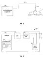
- Fig. I is a schematic illustration of an electrosurgical system according to one embodiment of the present disclosure.
- the system includes an electrosurgical instrument 10 having one or more electrodes for treating tissue of a patient P.
- the instrument 10 may be either of monopolar type including one or more active electrodes (e.g., electrosurgical cutting probe, ablation electrode(s), etc.) or of bipolar type including one or more active and return electrodes (e.g., electrosurgical sealing forceps).
- Electrosurgical RF energy is supplied to the instrument 10 by a generator 20 via a supply line 12, which is connected to an active output terminal, allowing the instrument 10 to coagulate, seal, ablate and/or otherwise treat tissue.
- the instrument 10 is of monopolar type, then energy may be returned to the generator 20 through a return electrode (not explicitly shown), which may be one or more electrode pads disposed on the patient's body.
- the system may include a plurality of return electrodes that are arranged to minimize the chances of damaged tissue by maximizing the overall contact area with the patient P.
- the generator 20 and the monopolar return electrode may be configured for monitoring so called "tissue-to-patient" contact to insure that sufficient contact exists therebetween to further minimize chances of tissue damage.
- the return electrode is disposed in proximity to the active electrode (e.g., on opposing jaws of bipolar forceps).
- the generator 20 may also include a plurality of supply and return terminals and a corresponding number of electrode leads.
- the RF output stage 28 generates a 100% duty cycle sinusoidal waveform in cut mode, which is best suited for ablating, fusing and dissecting tissue and a 1-25% duty cycle waveform in coagulation mode, which is best used for cauterizing tissue to stop bleeding.
- a closed loop control scheme is a feedback control loop wherein sensor circuitry 22, which may include a plurality of sensors measuring a variety of tissue and energy properties (e.g., tissue impedance, tissue temperature, output current and/or voltage, etc.), provides feedback to the controller 24. Such sensors are within the purview of those skilled in the art.
- the controller 24 then signals the HVPS 27 and/or RF output stage 28, which then adjust DC and/or RF power supply, respectively.
- the controller 24 also receives input signals from the input controls of the generator 20 or the instrument 10.
- the controller 24 utilizes the input signals to adjust power outputted by the generator 20 and/or performs other control functions thereon.
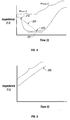
- Fig. 4 shows an impedance over time graph illustrating various phases that tissue undergoes during particular application of energy thereto.
- the decrease in tissue impedance as energy is applied thereto occurs when tissue is being fused (e.g., vessel sealing), ablated, or desiccated.
- tissue heating results in a decreasing impedance toward a minimum value that is below the initial sensed impedance.
- tissue impedance begins to rise almost immediately when tissue is being coagulated and vaporized as shown in Fig. 5 and discussed in more detail below.
- the method shown in Fig. 3 will now be discussed with regard to the fusion, ablation and desiccation applications.
- phase 1 which is a pre-heating or early desiccation stage
- level of energy supplied to the tissue is sufficiently low and impedance of the tissue starts at an initial impedance value.
- temperature therein rises and tissue impedance decreases.
- tissue impedance reaches a minimum impedance value 201 that correlates to tissue temperature of approximately 100° C, a boiling temperature for intra- and extra-cellular fluid boiling temperature.
- Phase II is a vaporization phase or a late desiccation phase, during which tissue has achieved a phase transition from a moist, conductive to dry, non-conductive properties.
- impedance begins to rise above the minimum impedance value 201.
- temperature may rise beyond the boiling point coinciding with minimum impedance value 201.
- tissue undergoes a phase change from moist state to a solid state and eventually a dried-out state.
- tissue is completely desiccated and eventually vaporized, producing steam, tissue vapors and charring.
- the interrogatory signal is an electric pulse and the tissue characteristic being measured may be energy, power, impedance, current, voltage, electrical phase angle, reflected power, temperature, etc.
- the interrogatory signal and the tissue properties being sensed may be another type of interrogatory signal.
- the interrogation signal may be achieved thermally, audibly, optically, ultrasonically, etc. and the initial tissue characteristic may then correspondingly be temperature, density, opaqueness, etc.
- a method according to the present disclosure is discussed using electrosurgical energy and corresponding tissue properties (e.g., impedance). Those skilled in the art will appreciate that the method may be adopted using other energy applications discussed above.
- step 110 the generator 20 supplies electrosurgical energy to the tissue through the instrument 10.
- step 120 during application of energy to the tissue, impedance is continually monitored by the sensor circuitry 22. In particular, voltage and current signals are monitored and corresponding impedance values are calculated at the sensor circuitry 22 and/or at the microprocessor 25. Power and other energy properties may also be calculated based on collected voltage and current signals.
- the microprocessor 25 stores the collected voltage, current, and impedance within the memory 26.
- the desired trajectory 200 includes a plurality of calculated target impedance values based on the desired input parameters (e.g., desired slope) from the starting point 210 to a desired end point 220 (e.g., minimum impedance value 201).
- the desired trajectory 200 may be linear, as shown in Fig. 4, quasi-linear or non-linear.
- step 140 the generator 20 drives impedance down from starting point 210 to the minimum impedance value 201 along the desired trajectory 200 by adjusting the energy level to match measured impedance values to corresponding target impedance values. This is accomplished at specific time increments, which may be predetermined or dynamically defined. Namely, for every time increment, tissue reaction is calculated and output of the generator 20 is controlled to match measured impedance to corresponding target impedance.
- target error is the difference between target impedance value and actual impedance value.
- This value is used to determine the application of energy required to obtain and/or maintain a desired impedance slope.
- the target error represents the amount that tissue impedance deviates from a corresponding target impedance value.
- the energy output is adjusted based on the value of the target error. If the target error shows that measured impedance is below the target impedance, output of the generator 20 is lowered. If the target error shows that measured impedance is above the target impedance, output of the generator 20 is increased.
- step 150 during the controlled heating stage, the minimum impedance value 201 is obtained.
- the system is continuously monitoring the tissue impedance for a minimum value. Impedance is continuously monitored by comparing a currently measured impedance value with a previously measured impedance and selecting the low of the two impedance values as the current minimum impedance.
- step 160 during the controlled heating stage, as the generator 20 drives the impedance down, target error is also being continuously monitored to determine if the error exceeds a predetermined threshold. This event helps to identify that the electrode-to-tissue interface as well as impedance is at a minimum and cannot be driven any lower.
- the target error may be combined with a clock timer to demark a deviation time after the target error exceeds a particular value.
- the minimum impedance value 201 may be considered during monitoring of the target error to determine a sustained deviation from the minimum or an instantaneous extraneous event (e.g., arcing).
- measured impedance is matched with target impedance so that tissue impedance decreases according to the desired impedance trajectory 210 until a particular tissue condition or predetermined impedance (e.g., minimum impedance value 201) is reached.
- a particular tissue condition or predetermined impedance e.g., minimum impedance value 201
- step 170 the point of desiccation and/or vaporization in phase II is identified by an increase in impedance above the dynamically measured minimum impedance value 201 combined by a deviation from the target value.
- the minimum impedance value 201 and the target error are monitored and obtained in steps 150 and 160, respectively, are used to determine if tissue has progressed to the phase II.
- This transformation may be defined by either the threshold being above the minimum of target error and/or an absolute or relative threshold defined by the user or by other inputs, such as a look-up table based on initial interrogation information.
- tissue and/or energy properties are compared with reference values to identify vaporization and/or desiccation.
- the system is looking for the impedance to rise above a threshold and the target to deviate a dynamic or a predetermine level instantaneously and/or over a predetermined time.
- step 180 controls the energy to complete the treatment application (e.g., fusion, ablation, sealing, etc.). After this point, energy output is controlled to maintain minimum impedance value 201. This optimizes energy delivery by maintaining the most appropriate RF energy levels to maintain heating. Energy delivery may be controlled using existing generators and algorithms, such as LigasureTM generators available from Valleylab, Inc. of Boulder, Colorado.
- tissue impedance does not drop and in contrast begins to rise almost immediately then tissue is being coagulated and vaporized.
- the difference in impedance behavior is attributable to the different energy parameters associated with coagulation and vaporization.
- An embodiment of the method shown in Fig. 3 is particularly discussed with regard to coagulation and vaporization.
- Fig. 5 shows an impedance plot illustrating impedance changes occurring within tissue during coagulation and vaporization with impedance increasing at the onset of energy application.
- a method according to the present disclosure can also be utilized to drive impedance along a desired positive sloping trajectory 300.
- the method for driving the impedance along the desired trajectory 300 is substantially similar to the method discussed above and shown in Fig. 3 with the only difference being that the desired trajectory 300 does not reach a minimum impedance and is driven along a positive slope.
Abstract
Description
- The present disclosure relates to a system and method for performing electrosurgical procedures. More particularly, the present disclosure relates to a system and method for controlling the heating rate of tissue prior to cellular vaporization by adjusting output of an electrosurgical generator based on sensed tissue feedback.
- Energy-based tissue treatment is well known in the art. Various types of energy (e.g., electrical, ultrasonic, microwave, cryo, heat, laser, etc.) are applied to tissue to achieve a desired result. Electrosurgery involves application of high radio frequency electrical current to a surgical site to cut, ablate, coagulate or seal tissue. In monopolar electrosurgery, a source or active electrode delivers radio frequency energy from the electrosurgical generator to the tissue and a return electrode carries the current back to the generator. In monopolar electrosurgery, the source electrode is typically part of the surgical instrument held by the surgeon and applied to the tissue to be treated. A patient return electrode is placed remotely from the active electrode to carry the current back to the generator.
- Ablation is most commonly a monopolar procedure that is particularly useful in the field of cancer treatment, where one or more RF ablation needle electrodes (usually of elongated cylindrical geometry) are inserted into a living body. A typical form of such needle electrodes incorporates an insulated sheath from which an exposed (uninsulated) tip extends. When an RF energy is provided between the return electrode and the inserted ablation electrode, RF current flows from the needle electrode through the body. Typically, the current density is very high near the tip of the needle electrode, which tends to heat and destroy surrounding issue.
- In bipolar electrosurgery, one of the electrodes of the hand-held instrument functions as the active electrode and the other as the return electrode. The return electrode is placed in close proximity to the active electrode such that an electrical circuit is formed between the two electrodes (e.g., electrosurgical forceps). In this manner, the applied electrical current is limited to the body tissue positioned between the electrodes. When the electrodes are sufficiently separated from one another, the electrical circuit is open and thus inadvertent contact with body tissue with either of the separated electrodes does not cause current to flow.
- It is known in the art that sensed tissue feedback may be used to control delivery of electrosurgical energy. Therefore, a need exists to develop an electrosurgical system and method that allow for precisely controlling output of an electrosurgical generator based on sensed tissue feedback.
- The present disclosure relates to a system and method for controlling energy output of an electrosurgical generator during initial phases of energy application. In particular, the system generates a desired impedance trajectory including a plurality of target impedance values, based on either dynamically obtained or predefined variables. Thereafter, the system monitors tissue impedance and adjusts output of the electrosurgical generator to match tissue impedance to corresponding target impedance values.
- According to one aspect of the present disclosure, an electrosurgical system is disclosed. The system includes an electrosurgical generator adapted to supply electrosurgical energy at an output level to tissue and to transmit an interrogatory signal to obtain initial tissue impedance and to derive a starting impedance value. The electrosurgical generator includes a microprocessor adapted to generate a desired impedance trajectory as a function of either of the initial tissue impedance or the starting impedance value. The desired impedance trajectory includes a plurality of target impedance values. The microprocessor is further adapted to drive tissue impedance along the desired impedance trajectory by adjusting the output level to substantially match tissue impedance to a corresponding target impedance value. The system also includes an electrosurgical instrument including at least one active electrode adapted to apply electrosurgical energy to tissue.
- According to another aspect of the present disclosure, a method for performing an electrosurgical procedure is disclosed. The method includes the steps of applying electrosurgical energy at an output level to tissue from an electrosurgical generator and transmitting an interrogatory signal to obtain initial tissue impedance to derive a starting impedance value. The method also includes the step of generating a desired impedance trajectory as a function of either the initial tissue impedance or the starting impedance value, wherein the desired impedance trajectory includes a plurality of target impedance values. The method further includes the step of driving tissue impedance along the desired impedance trajectory by adjusting the output level to substantially match tissue impedance to a corresponding target impedance value.
- According to a further aspect of the present disclosure, an electrosurgical generator is disclosed. The electrosurgical generator includes sensor circuitry adapted to supply energy at an output level to tissue. The electrosurgical generator is adapted to transmit an interrogatory signal to obtain initial tissue impedance to derive a starting impedance value. The electrosurgical generator also includes a microprocessor adapted to generate a desired impedance trajectory as a function of either the initial tissue impedance or the starting impedance value, wherein the desired impedance trajectory includes a plurality of target impedance values. The electrosurgical generator is adapted to drive tissue impedance along the desired impedance trajectory by adjusting the output level to substantially match tissue impedance to a corresponding target impedance value.
- Various embodiments of the present disclosure are described herein with reference to the drawings wherein:
- Fig. 1 is a schematic block diagram of an electrosurgical system according to one embodiment of the present disclosure;
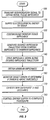
- Fig. 2 is a schematic block diagram of a generator according to one embodiment of the present disclosure;
- Fig. 3 is a flow diagram illustrating a method according to one embodiment of the present disclosure;
- Fig. 4 is an illustrative graph of impedance versus time showing the changes in impedance that occur within tissue during application of RF energy thereto; and
- Fig. 5 is an illustrative graph of impedance versus time showing the changes in impedance that occur within tissue during application of RF energy thereto.
- Particular embodiments of the present disclosure are described hereinbelow with reference to the accompanying drawings. In the following description, well-known functions or constructions are not described in detail to avoid obscuring the present disclosure in unnecessary detail. Those skilled in the art will understand that the method according to the present disclosure may be adapted to monitor use with either monopolar or bipolar electrosurgical systems.
- The methods may be extended to other tissue effects and energy-based modalities, including, but not limited to, ultrasonic, laser, microwave, and cryo tissue treatments. The disclosed methods are also based on impedance measurement and monitoring but other suitable tissue and energy properties may be used to determine state of the tissue, such as temperature, current, voltage, power, energy, phase of voltage and current. The method may be carried out using a feedback system incorporated into an electrosurgical system or may be a stand-alone modular embodiment (e.g., removable modular circuit configured to be electrically coupled to various components, such as a generator, of the electrosurgical system).
- A method according to the present disclosure controls rate of tissue changes during preheating and/or early desiccation phases that occur prior to vaporization of intra-cellular and/or extra-cellular fluids by matching tissue impedance to target impedance based on desired rate of change of impedance over time. Hence, a method according to present disclosure may be utilized with feedback control methods that adjust energy output in response to measured tissue impedance. In particular, energy output may be adjusted before tissue phase transition to control the rate of desiccation and vaporization phases.
- Fig. I is a schematic illustration of an electrosurgical system according to one embodiment of the present disclosure. The system includes an
electrosurgical instrument 10 having one or more electrodes for treating tissue of a patient P. Theinstrument 10 may be either of monopolar type including one or more active electrodes (e.g., electrosurgical cutting probe, ablation electrode(s), etc.) or of bipolar type including one or more active and return electrodes (e.g., electrosurgical sealing forceps). Electrosurgical RF energy is supplied to theinstrument 10 by agenerator 20 via asupply line 12, which is connected to an active output terminal, allowing theinstrument 10 to coagulate, seal, ablate and/or otherwise treat tissue. - If the
instrument 10 is of monopolar type, then energy may be returned to thegenerator 20 through a return electrode (not explicitly shown), which may be one or more electrode pads disposed on the patient's body. The system may include a plurality of return electrodes that are arranged to minimize the chances of damaged tissue by maximizing the overall contact area with the patient P. In addition, thegenerator 20 and the monopolar return electrode may be configured for monitoring so called "tissue-to-patient" contact to insure that sufficient contact exists therebetween to further minimize chances of tissue damage. - If the
instrument 10 is of bipolar type, the return electrode is disposed in proximity to the active electrode (e.g., on opposing jaws of bipolar forceps). Thegenerator 20 may also include a plurality of supply and return terminals and a corresponding number of electrode leads. - The
generator 20 includes input controls (e.g., buttons, activators, switches, touch screen, etc.) for controlling thegenerator 20. In addition, thegenerator 20 may include one or more display screens for providing the surgeon with variety of output information (e.g., intensity settings, treatment complete indicators, etc.). The controls allow the surgeon to adjust power of the RF energy, waveform, and other parameters to achieve the desired waveform suitable for a particular task (e.g., coagulating, tissue sealing, intensity setting, etc.). Theinstrument 10 may also include a plurality of input controls that may be redundant with certain input controls of thegenerator 20. Placing the input controls at theinstrument 10 allows for easier and faster modification of RF energy parameters during the surgical procedure without requiring interaction with thegenerator 20. - Fig. 2 shows a schematic block diagram of the
generator 20 having acontroller 24, a high voltage DC power supply 27 ("HVPS") and anRF output stage 28. TheHVPS 27 provides high voltage DC power to anRF output stage 28 which then converts high voltage DC power into RF energy and delivers the RF energy to theactive electrode 24. In particular, theRF output stage 28 generates sinusoidal waveforms of high RF energy. TheRF output stage 28 is configured to generate a plurality of waveforms having various duty cycles, peak voltages, crest factors, and other suitable parameters. Certain types of waveforms are suitable for specific electrosurgical modes. For instance, theRF output stage 28 generates a 100% duty cycle sinusoidal waveform in cut mode, which is best suited for ablating, fusing and dissecting tissue and a 1-25% duty cycle waveform in coagulation mode, which is best used for cauterizing tissue to stop bleeding. - The
controller 24 includes amicroprocessor 25 operably connected to amemory 26, which may be volatile type memory (e.g., RAM) and/or non-volatile type memory (e.g., flash media, disk media, etc.). Themicroprocessor 25 includes an output port that is operably connected to theHVPS 27 and/orRF output stage 28 allowing themicroprocessor 25 to control the output of thegenerator 20 according to either open and/or closed control loop schemes. Those skilled in the art will appreciate that themicroprocessor 25 may be substituted by any logic processor (e.g., control circuit) adapted to perform the calculations discussed herein. - A closed loop control scheme is a feedback control loop wherein
sensor circuitry 22, which may include a plurality of sensors measuring a variety of tissue and energy properties (e.g., tissue impedance, tissue temperature, output current and/or voltage, etc.), provides feedback to thecontroller 24. Such sensors are within the purview of those skilled in the art. Thecontroller 24 then signals theHVPS 27 and/orRF output stage 28, which then adjust DC and/or RF power supply, respectively. Thecontroller 24 also receives input signals from the input controls of thegenerator 20 or theinstrument 10. Thecontroller 24 utilizes the input signals to adjust power outputted by thegenerator 20 and/or performs other control functions thereon. - Fig. 4 shows an impedance over time graph illustrating various phases that tissue undergoes during particular application of energy thereto. The decrease in tissue impedance as energy is applied thereto occurs when tissue is being fused (e.g., vessel sealing), ablated, or desiccated. In particular, during tissue fusion, ablation, or desiccation, tissue heating results in a decreasing impedance toward a minimum value that is below the initial sensed impedance. However, tissue impedance begins to rise almost immediately when tissue is being coagulated and vaporized as shown in Fig. 5 and discussed in more detail below. The method shown in Fig. 3 will now be discussed with regard to the fusion, ablation and desiccation applications.
- During phase 1, which is a pre-heating or early desiccation stage, level of energy supplied to the tissue is sufficiently low and impedance of the tissue starts at an initial impedance value. As more energy is applied to the tissue, temperature therein rises and tissue impedance decreases. At a later point in-time, tissue impedance reaches a
minimum impedance value 201 that correlates to tissue temperature of approximately 100° C, a boiling temperature for intra- and extra-cellular fluid boiling temperature. - Phase II is a vaporization phase or a late desiccation phase, during which tissue has achieved a phase transition from a moist, conductive to dry, non-conductive properties. In particular, as the majority of the intra- and extra-cellular fluids begin to rapidly boil during the end of phase I, impedance begins to rise above the
minimum impedance value 201. As sufficient energy is continually applied to the tissue during phase II, temperature may rise beyond the boiling point coinciding withminimum impedance value 201. As impedance continues to rise, tissue undergoes a phase change from moist state to a solid state and eventually a dried-out state. As further energy is applied, tissue is completely desiccated and eventually vaporized, producing steam, tissue vapors and charring. - Previous impedance control algorithms during phase I generally applied energy uncontrollably to tissue allowing impedance to drop rapidly until reaching the
minimum impedance value 201. As energy is continually delivered to tissue, the tissue can rapidly and uncontrollably transition through theminimum impedance value 201. Maintaining impedance at theminimum impedance value 201 is particularly desirable since the minimum impedance coincides with maximum conductance. Hence, it has been determined that controlling the rate at whichminimum impedance value 201 provides enforced tissue effects. However,minimum impedance value 201 depends on many factors including tissue type, tissue hydration level, electrode contact area, distance between electrodes, applied energy, etc. Some embodiments of the present disclosure provides a system and method for controlling the rate of tissue change during phase I and prior to tissue transitioning into phase II in light of these many variable tissue factors. - Fig. 3 shows a method according to one embodiment of the present disclosure for controlling output of the generator in response to monitored tissue impedance. In
step 100, theinstrument 10 is brought into a treatment site of the tissue and a low power interrogatory signal is transmitted to the tissue to obtain an initial tissue characteristic. The interrogatory signal is transmitted prior to application of electrosurgical energy. This initial tissue characteristic describes the natural tissue state and is used in subsequent calculations to determine a target slope or trajectory corresponding to a desired tissue response during phase I. - If electrosurgical energy is being used to treat the tissue, then the interrogatory signal is an electric pulse and the tissue characteristic being measured may be energy, power, impedance, current, voltage, electrical phase angle, reflected power, temperature, etc. If other energy is being used to treat tissue then the interrogatory signal and the tissue properties being sensed may be another type of interrogatory signal. For instance the interrogation signal may be achieved thermally, audibly, optically, ultrasonically, etc. and the initial tissue characteristic may then correspondingly be temperature, density, opaqueness, etc. A method according to the present disclosure is discussed using electrosurgical energy and corresponding tissue properties (e.g., impedance). Those skilled in the art will appreciate that the method may be adopted using other energy applications discussed above.
- In
step 110, thegenerator 20 supplies electrosurgical energy to the tissue through theinstrument 10. Instep 120, during application of energy to the tissue, impedance is continually monitored by thesensor circuitry 22. In particular, voltage and current signals are monitored and corresponding impedance values are calculated at thesensor circuitry 22 and/or at themicroprocessor 25. Power and other energy properties may also be calculated based on collected voltage and current signals. Themicroprocessor 25 stores the collected voltage, current, and impedance within thememory 26. - In
step 130, target impedance values are calculated based on the initial tissue characteristic and a desired target slope. In particular, target impedance values take the form of a desiredimpedance trajectory 200 when considering the position of target impedance values over time. The desiredtrajectory 200 is drawn to theminimum impedance value 201. More specifically, astart point 210 is defined based on the initial interrogation signal. Thestart point 210 is directly measured (e.g., corresponding to the initial tissue impedance) and calculated by thegenerator 20. The desiredtrajectory 210 may be predetermined value imported from a look-up table stored inmemory 26 or a hard-coded input. The predetermined value and the hard-coded input may be selected based on the initial tissue impedance. Thus, the desiredtrajectory 200 includes a plurality of calculated target impedance values based on the desired input parameters (e.g., desired slope) from thestarting point 210 to a desired end point 220 (e.g., minimum impedance value 201). The desiredtrajectory 200 may be linear, as shown in Fig. 4, quasi-linear or non-linear. - In
step 140, thegenerator 20 drives impedance down fromstarting point 210 to theminimum impedance value 201 along the desiredtrajectory 200 by adjusting the energy level to match measured impedance values to corresponding target impedance values. This is accomplished at specific time increments, which may be predetermined or dynamically defined. Namely, for every time increment, tissue reaction is calculated and output of thegenerator 20 is controlled to match measured impedance to corresponding target impedance. - As the application of energy continues adjusting its output and matching impedance along the desired
trajectory 210, thegenerator 20 continuously monitors target error, which is the difference between target impedance value and actual impedance value. This value is used to determine the application of energy required to obtain and/or maintain a desired impedance slope. Namely, the target error represents the amount that tissue impedance deviates from a corresponding target impedance value. Hence, the energy output is adjusted based on the value of the target error. If the target error shows that measured impedance is below the target impedance, output of thegenerator 20 is lowered. If the target error shows that measured impedance is above the target impedance, output of thegenerator 20 is increased. - In
step 150, during the controlled heating stage, theminimum impedance value 201 is obtained. As energy is being applied and the target and tissue impedance is being decremented, the system is continuously monitoring the tissue impedance for a minimum value. Impedance is continuously monitored by comparing a currently measured impedance value with a previously measured impedance and selecting the low of the two impedance values as the current minimum impedance. - In
step 160, during the controlled heating stage, as thegenerator 20 drives the impedance down, target error is also being continuously monitored to determine if the error exceeds a predetermined threshold. This event helps to identify that the electrode-to-tissue interface as well as impedance is at a minimum and cannot be driven any lower. The target error may be combined with a clock timer to demark a deviation time after the target error exceeds a particular value. Theminimum impedance value 201 may be considered during monitoring of the target error to determine a sustained deviation from the minimum or an instantaneous extraneous event (e.g., arcing).
During the controlled heating stage, as described instep 140, measured impedance is matched with target impedance so that tissue impedance decreases according to the desiredimpedance trajectory 210 until a particular tissue condition or predetermined impedance (e.g., minimum impedance value 201) is reached. - In
step 170, the point of desiccation and/or vaporization in phase II is identified by an increase in impedance above the dynamically measuredminimum impedance value 201 combined by a deviation from the target value. Thus, theminimum impedance value 201 and the target error are monitored and obtained insteps - Once the event coinciding with the start of desiccation and/or vaporization is identified,
step 180 controls the energy to complete the treatment application (e.g., fusion, ablation, sealing, etc.). After this point, energy output is controlled to maintainminimum impedance value 201. This optimizes energy delivery by maintaining the most appropriate RF energy levels to maintain heating. Energy delivery may be controlled using existing generators and algorithms, such as Ligasure™ generators available from Valleylab, Inc. of Boulder, Colorado. - As discussed above, if the tissue impedance does not drop and in contrast begins to rise almost immediately then tissue is being coagulated and vaporized. The difference in impedance behavior is attributable to the different energy parameters associated with coagulation and vaporization. An embodiment of the method shown in Fig. 3 is particularly discussed with regard to coagulation and vaporization.
- In the case of coagulation and vaporization applications, energy is applied to achieve rapid tissue phase transition (i.e., into phase II). Fig. 5 shows an impedance plot illustrating impedance changes occurring within tissue during coagulation and vaporization with impedance increasing at the onset of energy application. Hence, in energy applications where rapid tissue phase transitioning is desired, a method according to the present disclosure can also be utilized to drive impedance along a desired positive
sloping trajectory 300. - The method for driving the impedance along the desired
trajectory 300 is substantially similar to the method discussed above and shown in Fig. 3 with the only difference being that the desiredtrajectory 300 does not reach a minimum impedance and is driven along a positive slope. - Determination as to whether the impedance is to be driven either in a decreasing or increasing direction is made prior to application. Namely, the selection is made by the user based on the clinical intent (e.g., fusion, desiccation, and ablation versus coagulation and vaporization), tissue type, mode of operation, instrument type, etc.
- While several embodiments of the disclosure have been shown in the drawings and/or discussed herein, it is not intended that the disclosure be limited thereto, as it is intended that the disclosure be as broad in scope as the art will allow and that the specification be read likewise. Therefore, the above description should not be construed as limiting, but merely as exemplifications of particular embodiments. Those skilled in the art will envision other modifications within the scope and spirit of the claims appended hereto.
Claims (13)
- An electrosurgical system comprising:an electrosurgical generator adapted to supply electrosurgical energy to tissue and to transmit an interrogatory signal to obtain initial tissue impedance and to derive a starting impedance value, the electrosurgical generator including:a microprocessor adapted to generate a desired impedance trajectory as a function of at least one of the initial tissue impedance and the starting impedance value, wherein the desired impedance trajectory includes a plurality of target impedance values, the microprocessor being adapted to drive tissue impedance along the desired impedance trajectory by adjusting the output level to substantially match tissue impedance to a corresponding target impedance value; andan electrosurgical instrument including at least one active electrode adapted to apply electrosurgical energy to tissue.
- An electrosurgical system according to claim 1, wherein the electrosurgical generator is further adapted to monitor a target error representing the difference between a tissue impedance and the corresponding target impedance value.
- An electrosurgical system according to claim 1, wherein the electrosurgical generator further includes sensor circuitry adapted to monitor tissue impedance to obtain a minimum impedance value.
- An electrosurgical system according to claim 1, wherein the slope of the desired impedance trajectory includes a positive slope.
- An electrosurgical system according to claim 1, wherein the slope of the desired impedance trajectory includes a negative slope.
- An electrosurgical system according to claim 1, wherein the slope of the desired impedance trajectory is at least one of a linear, quasi-linear, and non-linear trajectory.
- An electrosurgical system according to claim 1, wherein the desired impedance trajectory represents a pre-desiccation phase of an electrosurgical procedure.
- An electrosurgical generator comprising sensor circuitry adapted to supply energy at an output level to tissue, the electrosurgical generator being adapted to transmit an interrogatory signal to obtain initial tissue impedance to derive a starting impedance value; and
a microprocessor adapted to generate a desired impedance trajectory as a function of at least one of the initial tissue impedance and the starting impedance value, wherein the desired impedance trajectory includes a plurality of target impedance values, the electrosurgical generator being adapted to drive tissue impedance along the desired impedance trajectory by adjusting the output level to match tissue impedance to a corresponding target impedance value. - An electrosurgical generator according to claim 8, wherein the electrosurgical generator is further adapted to monitor a target error representing the difference between a tissue impedance and the corresponding target impedance value.
- An electrosurgical generator according to claim 8, wherein the electrosurgical generator further includes sensor circuitry adapted to monitor tissue impedance to obtain a minimum impedance value.
- An electrosurgical generator according to claim 8, wherein the slope of the desired impedance trajectory includes a positive slope.
- An electrosurgical generator according to claim 8, wherein the slope of the desired impedance trajectory includes a negative slope.
- An electrosurgical generator according to claim 8, wherein the desired impedance trajectory represents a pre-desiccation phase of an electrosurgical procedure.
Applications Claiming Priority (1)
| Application Number | Priority Date | Filing Date | Title |
|---|---|---|---|
| US11/442,785 US20070282320A1 (en) | 2006-05-30 | 2006-05-30 | System and method for controlling tissue heating rate prior to cellular vaporization |
Publications (2)
| Publication Number | Publication Date |
|---|---|
| EP1862137A1 true EP1862137A1 (en) | 2007-12-05 |
| EP1862137B1 EP1862137B1 (en) | 2011-05-25 |
Family
ID=38510342
Family Applications (1)
| Application Number | Title | Priority Date | Filing Date |
|---|---|---|---|
| EP07010673A Active EP1862137B1 (en) | 2006-05-30 | 2007-05-30 | System for controlling tissue heating rate prior to cellular vaporization |
Country Status (6)
| Country | Link |
|---|---|
| US (1) | US20070282320A1 (en) |
| EP (1) | EP1862137B1 (en) |
| JP (1) | JP5198800B2 (en) |
| AU (1) | AU2007202464B2 (en) |
| CA (1) | CA2590457A1 (en) |
| ES (1) | ES2366450T3 (en) |
Cited By (24)
| Publication number | Priority date | Publication date | Assignee | Title |
|---|---|---|---|---|
| EP2206471A1 (en) * | 2009-01-12 | 2010-07-14 | Tyco Healthcare Group LP | Energy delivery algorithm for medical devices |
| EP2213256A1 (en) * | 2009-01-12 | 2010-08-04 | Tyco Healthcare Group LP | Energy delivery algorithm impedance trend adaptation |
| EP2213255A1 (en) * | 2009-01-12 | 2010-08-04 | Tyco Healthcare Group LP | Energy delivery algorithm for medical devices |
| EP2221017A1 (en) * | 2009-02-23 | 2010-08-25 | Covidien AG | System and method for tissue sealing |
| WO2011032729A1 (en) | 2009-09-21 | 2011-03-24 | Erbe Elektromedizin Gmbh | Supply device for operating at least one medical instrument, method for generating a control program |
| EP2409661A1 (en) * | 2010-07-19 | 2012-01-25 | Tyco Healthcare Group, LP | Hydraulic conductive monitoring to initiate tissue division |
| EP2415416A1 (en) * | 2010-07-23 | 2012-02-08 | Conmed Corporation | Tissue fusion system and method of performing a functional verification test |
| US8152802B2 (en) | 2009-01-12 | 2012-04-10 | Tyco Healthcare Group Lp | Energy delivery algorithm filter pre-loading |
| US8211100B2 (en) | 2009-01-12 | 2012-07-03 | Tyco Healthcare Group Lp | Energy delivery algorithm for medical devices based on maintaining a fixed position on a tissue electrical conductivity v. temperature curve |
| US8262652B2 (en) | 2009-01-12 | 2012-09-11 | Tyco Healthcare Group Lp | Imaginary impedance process monitoring and intelligent shut-off |
| EP2514380A1 (en) * | 2011-04-21 | 2012-10-24 | Erbe Elektromedizin GmbH | Electrical surgical device with improved cutting |
| EP2520240A1 (en) | 2011-05-03 | 2012-11-07 | Erbe Elektromedizin GmbH | Method and device for tissue fusion or coagulation by means of electric force with negative source impedance |
| EP2520241A1 (en) | 2011-05-03 | 2012-11-07 | Erbe Elektromedizin GmbH | Method and device for tissue fusion or coagulation by means of tissue resistance-dependent voltage-controlled electric force |
| US8636730B2 (en) | 2010-07-12 | 2014-01-28 | Covidien Lp | Polarity control of electrosurgical generator |
| EP2805682A1 (en) | 2013-05-24 | 2014-11-26 | Erbe Elektromedizin GmbH | Power controlled coagulation device |
| EP2992848A1 (en) | 2014-09-05 | 2016-03-09 | ERBE Elektromedizin GmbH | Device for contact coagulation of biological tissue |
| US9375249B2 (en) | 2012-05-11 | 2016-06-28 | Covidien Lp | System and method for directing energy to tissue |
| US9529025B2 (en) | 2012-06-29 | 2016-12-27 | Covidien Lp | Systems and methods for measuring the frequency of signals generated by high frequency medical devices |
| US9539050B2 (en) | 2011-04-12 | 2017-01-10 | Covidien Lp | System and method for process monitoring and intelligent shut-off |
| US9636165B2 (en) | 2013-07-29 | 2017-05-02 | Covidien Lp | Systems and methods for measuring tissue impedance through an electrosurgical cable |
| US9768373B2 (en) | 2003-10-30 | 2017-09-19 | Covidien Ag | Switched resonant ultrasonic power amplifier system |
| US9872719B2 (en) | 2013-07-24 | 2018-01-23 | Covidien Lp | Systems and methods for generating electrosurgical energy using a multistage power converter |
| WO2020227519A1 (en) * | 2019-05-09 | 2020-11-12 | Gyrus Acmi, Inc. D/B/A Olympus Surgical Technologies America | Electrosurgical systems and methods |
| US11666372B2 (en) | 2019-05-09 | 2023-06-06 | Gyrus Acmi, Inc. | Alternate power correction outputs in electrosurgical systems |
Families Citing this family (67)
| Publication number | Priority date | Publication date | Assignee | Title |
|---|---|---|---|---|
| US7137980B2 (en) | 1998-10-23 | 2006-11-21 | Sherwood Services Ag | Method and system for controlling output of RF medical generator |
| US7364577B2 (en) | 2002-02-11 | 2008-04-29 | Sherwood Services Ag | Vessel sealing system |
| US7901400B2 (en) | 1998-10-23 | 2011-03-08 | Covidien Ag | Method and system for controlling output of RF medical generator |
| JP4490807B2 (en) | 2002-05-06 | 2010-06-30 | コヴィディエン アクチェンゲゼルシャフト | System for electrically detecting blood and controlling the generator during electrosurgical procedures |
| US7044948B2 (en) | 2002-12-10 | 2006-05-16 | Sherwood Services Ag | Circuit for controlling arc energy from an electrosurgical generator |
| US8012150B2 (en) | 2003-05-01 | 2011-09-06 | Covidien Ag | Method and system for programming and controlling an electrosurgical generator system |
| EP2037511A3 (en) * | 2003-09-24 | 2009-04-22 | Kyocera Corporation | Multilayer piezoelectric element |
| US8104956B2 (en) | 2003-10-23 | 2012-01-31 | Covidien Ag | Thermocouple measurement circuit |
| US7131860B2 (en) | 2003-11-20 | 2006-11-07 | Sherwood Services Ag | Connector systems for electrosurgical generator |
| US7766905B2 (en) | 2004-02-12 | 2010-08-03 | Covidien Ag | Method and system for continuity testing of medical electrodes |
| US7780662B2 (en) | 2004-03-02 | 2010-08-24 | Covidien Ag | Vessel sealing system using capacitive RF dielectric heating |
| US7628786B2 (en) | 2004-10-13 | 2009-12-08 | Covidien Ag | Universal foot switch contact port |
| US9474564B2 (en) | 2005-03-31 | 2016-10-25 | Covidien Ag | Method and system for compensating for external impedance of an energy carrying component when controlling an electrosurgical generator |
| US8728072B2 (en) | 2005-05-12 | 2014-05-20 | Aesculap Ag | Electrocautery method and apparatus |
| US9339323B2 (en) | 2005-05-12 | 2016-05-17 | Aesculap Ag | Electrocautery method and apparatus |
| US8696662B2 (en) | 2005-05-12 | 2014-04-15 | Aesculap Ag | Electrocautery method and apparatus |
| US8734438B2 (en) | 2005-10-21 | 2014-05-27 | Covidien Ag | Circuit and method for reducing stored energy in an electrosurgical generator |
| US7947039B2 (en) | 2005-12-12 | 2011-05-24 | Covidien Ag | Laparoscopic apparatus for performing electrosurgical procedures |
| US8216223B2 (en) | 2006-01-24 | 2012-07-10 | Covidien Ag | System and method for tissue sealing |
| US8147485B2 (en) | 2006-01-24 | 2012-04-03 | Covidien Ag | System and method for tissue sealing |
| US9186200B2 (en) | 2006-01-24 | 2015-11-17 | Covidien Ag | System and method for tissue sealing |
| CA2574935A1 (en) | 2006-01-24 | 2007-07-24 | Sherwood Services Ag | A method and system for controlling an output of a radio-frequency medical generator having an impedance based control algorithm |
| US20070173813A1 (en) * | 2006-01-24 | 2007-07-26 | Sherwood Services Ag | System and method for tissue sealing |
| US7513896B2 (en) | 2006-01-24 | 2009-04-07 | Covidien Ag | Dual synchro-resonant electrosurgical apparatus with bi-directional magnetic coupling |
| AU2007200299B2 (en) | 2006-01-24 | 2012-11-15 | Covidien Ag | System and method for tissue sealing |
| CA2574934C (en) | 2006-01-24 | 2015-12-29 | Sherwood Services Ag | System and method for closed loop monitoring of monopolar electrosurgical apparatus |
| US7651493B2 (en) | 2006-03-03 | 2010-01-26 | Covidien Ag | System and method for controlling electrosurgical snares |
| US7648499B2 (en) | 2006-03-21 | 2010-01-19 | Covidien Ag | System and method for generating radio frequency energy |
| US7651492B2 (en) | 2006-04-24 | 2010-01-26 | Covidien Ag | Arc based adaptive control system for an electrosurgical unit |
| US8574229B2 (en) | 2006-05-02 | 2013-11-05 | Aesculap Ag | Surgical tool |
| US8753334B2 (en) | 2006-05-10 | 2014-06-17 | Covidien Ag | System and method for reducing leakage current in an electrosurgical generator |
| US7731717B2 (en) | 2006-08-08 | 2010-06-08 | Covidien Ag | System and method for controlling RF output during tissue sealing |
| US8034049B2 (en) | 2006-08-08 | 2011-10-11 | Covidien Ag | System and method for measuring initial tissue impedance |
| US7794457B2 (en) | 2006-09-28 | 2010-09-14 | Covidien Ag | Transformer for RF voltage sensing |
| US8777941B2 (en) | 2007-05-10 | 2014-07-15 | Covidien Lp | Adjustable impedance electrosurgical electrodes |
| US7834484B2 (en) | 2007-07-16 | 2010-11-16 | Tyco Healthcare Group Lp | Connection cable and method for activating a voltage-controlled generator |
| US8216220B2 (en) | 2007-09-07 | 2012-07-10 | Tyco Healthcare Group Lp | System and method for transmission of combined data stream |
| US8512332B2 (en) | 2007-09-21 | 2013-08-20 | Covidien Lp | Real-time arc control in electrosurgical generators |
| US8280525B2 (en) * | 2007-11-16 | 2012-10-02 | Vivant Medical, Inc. | Dynamically matched microwave antenna for tissue ablation |
| US8870867B2 (en) | 2008-02-06 | 2014-10-28 | Aesculap Ag | Articulable electrosurgical instrument with a stabilizable articulation actuator |
| US8221418B2 (en) | 2008-02-07 | 2012-07-17 | Tyco Healthcare Group Lp | Endoscopic instrument for tissue identification |
| EP2319447B1 (en) * | 2008-03-31 | 2012-08-22 | Applied Medical Resources Corporation | Electrosurgical tool with jaws actuatable by a force regulation mechanism |
| US8226639B2 (en) | 2008-06-10 | 2012-07-24 | Tyco Healthcare Group Lp | System and method for output control of electrosurgical generator |
| US20100130976A1 (en) * | 2008-11-21 | 2010-05-27 | Smith & Nephew Inc. | Reducing cross-talk effects in an rf electrosurgical device |
| US8568401B2 (en) | 2009-10-27 | 2013-10-29 | Covidien Lp | System for monitoring ablation size |
| US8382750B2 (en) | 2009-10-28 | 2013-02-26 | Vivant Medical, Inc. | System and method for monitoring ablation size |
| EP2526883A4 (en) * | 2010-01-22 | 2017-07-12 | Olympus Corporation | Treatment tool, treatment device, and treatment method |
| KR20120139661A (en) | 2010-02-04 | 2012-12-27 | 아에스쿨랍 아게 | Laparoscopic radiofrequency surgical device |
| US8827992B2 (en) | 2010-03-26 | 2014-09-09 | Aesculap Ag | Impedance mediated control of power delivery for electrosurgery |
| US8419727B2 (en) | 2010-03-26 | 2013-04-16 | Aesculap Ag | Impedance mediated power delivery for electrosurgery |
| US9173698B2 (en) | 2010-09-17 | 2015-11-03 | Aesculap Ag | Electrosurgical tissue sealing augmented with a seal-enhancing composition |
| ES2664081T3 (en) | 2010-10-01 | 2018-04-18 | Applied Medical Resources Corporation | Electrosurgical system with a radio frequency amplifier and with means for adapting to the separation between electrodes |
| US9339327B2 (en) | 2011-06-28 | 2016-05-17 | Aesculap Ag | Electrosurgical tissue dissecting device |
| US9044238B2 (en) | 2012-04-10 | 2015-06-02 | Covidien Lp | Electrosurgical monopolar apparatus with arc energy vascular coagulation control |
| BR122020022677B1 (en) | 2012-09-26 | 2023-01-10 | Aesculap Ag | ELECTRO SURGICAL DEVICE FOR CUTTING AND SEALING TISSUES |
| US20140371735A1 (en) * | 2013-06-12 | 2014-12-18 | Ethicon Endo-Surgery, Inc. | Electrosurgical instrument end effector with preheating element |
| WO2015100111A1 (en) | 2013-12-23 | 2015-07-02 | Hologic, Inc. | Power modulated endometrial lining tissue ablation |
| JP6573663B2 (en) | 2014-05-16 | 2019-09-11 | アプライド メディカル リソーシーズ コーポレイション | Electrosurgical system |
| AU2015266619B2 (en) | 2014-05-30 | 2020-02-06 | Applied Medical Resources Corporation | Electrosurgical instrument for fusing and cutting tissue and an electrosurgical generator |
| EP3236870B1 (en) | 2014-12-23 | 2019-11-06 | Applied Medical Resources Corporation | Bipolar electrosurgical sealer and divider |
| USD748259S1 (en) | 2014-12-29 | 2016-01-26 | Applied Medical Resources Corporation | Electrosurgical instrument |
| WO2017018023A1 (en) | 2015-07-30 | 2017-02-02 | オリンパス株式会社 | Method for operating power supply device, power supply device, and high-frequency treatment system |
| WO2017018025A1 (en) * | 2015-07-30 | 2017-02-02 | オリンパス株式会社 | Operation method for power supply device, power supply device, and high-frequency treatment system |
| JP6246418B2 (en) | 2015-07-30 | 2017-12-13 | オリンパス株式会社 | Power supply device operating method, power supply device, and high-frequency treatment system |
| WO2018158913A1 (en) | 2017-03-02 | 2018-09-07 | オリンパス株式会社 | Power source device, high-frequency processing system, and operation method for power source device |
| CA3111558A1 (en) | 2018-09-05 | 2020-03-12 | Applied Medical Resources Corporation | Electrosurgical generator control system |
| US11696796B2 (en) | 2018-11-16 | 2023-07-11 | Applied Medical Resources Corporation | Electrosurgical system |
Citations (4)
| Publication number | Priority date | Publication date | Assignee | Title |
|---|---|---|---|---|
| EP1151725A1 (en) * | 1994-09-23 | 2001-11-07 | Ethicon Endo-Surgery | Impedance feedback monitor for electrosurgical instrument |
| US20030158551A1 (en) * | 2002-02-19 | 2003-08-21 | Paton Boris E. | System and method for control of tissue welding |
| US20050101951A1 (en) | 1998-10-23 | 2005-05-12 | Robert Wham | Vessel sealing system |
| EP1810630A1 (en) | 2006-01-24 | 2007-07-25 | Sherwood Services AG | System for terminating treatment in impedance feedback algorithm |
Family Cites Families (99)
| Publication number | Priority date | Publication date | Assignee | Title |
|---|---|---|---|---|
| US1841968A (en) * | 1924-08-16 | 1932-01-19 | William J Cameron | Radio-surgical apparatus |
| US1787709A (en) * | 1928-06-11 | 1931-01-06 | Wappler Frederick Charles | High-frequency surgical cutting device |
| US1945867A (en) * | 1932-04-27 | 1934-02-06 | Technical Equipment Company | High frequency oscillatory apparatus for electrotherapeutic and sterilization purposes |
| US3495584A (en) * | 1965-06-03 | 1970-02-17 | Gen Electric | Lead failure detection circuit for a cardiac monitor |
| US3562623A (en) * | 1968-07-16 | 1971-02-09 | Hughes Aircraft Co | Circuit for reducing stray capacity effects in transformer windings |
| US3642008A (en) * | 1968-09-25 | 1972-02-15 | Medical Plastics Inc | Ground electrode and test circuit |
| US3641422A (en) * | 1970-10-01 | 1972-02-08 | Robert P Farnsworth | Wide band boost regulator power supply |
| US3933157A (en) * | 1973-10-23 | 1976-01-20 | Aktiebolaget Stille-Werner | Test and control device for electrosurgical apparatus |
| US4005714A (en) * | 1975-05-03 | 1977-02-01 | Richard Wolf Gmbh | Bipolar coagulation forceps |
| US4074719A (en) * | 1975-07-12 | 1978-02-21 | Kurt Semm | Method of and device for causing blood coagulation |
| US4188927A (en) * | 1978-01-12 | 1980-02-19 | Valleylab, Inc. | Multiple source electrosurgical generator |
| US4311154A (en) * | 1979-03-23 | 1982-01-19 | Rca Corporation | Nonsymmetrical bulb applicator for hyperthermic treatment of the body |
| US4314559A (en) * | 1979-12-12 | 1982-02-09 | Corning Glass Works | Nonstick conductive coating |
| US4494541A (en) * | 1980-01-17 | 1985-01-22 | Medical Plastics, Inc. | Electrosurgery safety monitor |
| US4372315A (en) * | 1980-07-03 | 1983-02-08 | Hair Free Centers | Impedance sensing epilator |
| US4565200A (en) * | 1980-09-24 | 1986-01-21 | Cosman Eric R | Universal lesion and recording electrode system |
| US4566454A (en) * | 1981-06-16 | 1986-01-28 | Thomas L. Mehl | Selected frequency hair removal device and method |
| US4429694A (en) * | 1981-07-06 | 1984-02-07 | C. R. Bard, Inc. | Electrosurgical generator |
| US5385544A (en) * | 1992-08-12 | 1995-01-31 | Vidamed, Inc. | BPH ablation method and apparatus |
| US4492231A (en) * | 1982-09-17 | 1985-01-08 | Auth David C | Non-sticking electrocautery system and forceps |
| US4492832A (en) * | 1982-12-23 | 1985-01-08 | Neomed, Incorporated | Hand-controllable switching device for electrosurgical instruments |
| US4644955A (en) * | 1982-12-27 | 1987-02-24 | Rdm International, Inc. | Circuit apparatus and method for electrothermal treatment of cancer eye |
| US4569345A (en) * | 1984-02-29 | 1986-02-11 | Aspen Laboratories, Inc. | High output electrosurgical unit |
| DE3775281D1 (en) * | 1986-06-16 | 1992-01-30 | Siemens Ag | DEVICE FOR CONTROLLING A HEART PACER BY MEANS OF IMPEDANCE ON BODY TISSUES. |
| JPH0511882Y2 (en) * | 1987-01-06 | 1993-03-25 | ||
| DE3805179A1 (en) * | 1988-02-19 | 1989-08-31 | Wolf Gmbh Richard | DEVICE WITH A ROTATING DRIVEN SURGICAL INSTRUMENT |
| US4890610A (en) * | 1988-05-15 | 1990-01-02 | Kirwan Sr Lawrence T | Bipolar forceps |
| US4903696A (en) * | 1988-10-06 | 1990-02-27 | Everest Medical Corporation | Electrosurgical generator |
| EP0390937B1 (en) * | 1989-04-01 | 1994-11-02 | Erbe Elektromedizin GmbH | Device for the surveillance of the adherence of neutral electrodes in high-frequency surgery |
| US4992719A (en) * | 1989-07-24 | 1991-02-12 | Hughes Aircraft Company | Stable high voltage pulse power supply |
| US6672151B1 (en) * | 1989-12-20 | 2004-01-06 | Sentech, Inc. | Apparatus and method for remote sensing and receiving |
| US5383917A (en) * | 1991-07-05 | 1995-01-24 | Jawahar M. Desai | Device and method for multi-phase radio-frequency ablation |
| DE4126608A1 (en) * | 1991-08-12 | 1993-02-18 | Fastenmeier Karl | ARRANGEMENT FOR CUTTING ORGANIC TISSUE WITH HIGH-FREQUENCY CURRENT |
| CA2075319C (en) * | 1991-09-26 | 1998-06-30 | Ernie Aranyi | Handle for surgical instruments |
| US5713896A (en) * | 1991-11-01 | 1998-02-03 | Medical Scientific, Inc. | Impedance feedback electrosurgical system |
| US5383874A (en) * | 1991-11-08 | 1995-01-24 | Ep Technologies, Inc. | Systems for identifying catheters and monitoring their use |
| GB9204217D0 (en) * | 1992-02-27 | 1992-04-08 | Goble Nigel M | Cauterising apparatus |
| US5300070A (en) * | 1992-03-17 | 1994-04-05 | Conmed Corporation | Electrosurgical trocar assembly with bi-polar electrode |
| US5282840A (en) * | 1992-03-26 | 1994-02-01 | Medtronic, Inc. | Multiple frequency impedance measurement system |
| US5281213A (en) * | 1992-04-16 | 1994-01-25 | Implemed, Inc. | Catheter for ice mapping and ablation |
| AU5456494A (en) * | 1992-11-13 | 1994-06-08 | American Cardiac Ablation Co., Inc. | Fluid cooled electrosurgical probe |
| GB9306637D0 (en) * | 1993-03-30 | 1993-05-26 | Smiths Industries Plc | Electrosurgery monitor and appartus |
| US5385148A (en) * | 1993-07-30 | 1995-01-31 | The Regents Of The University Of California | Cardiac imaging and ablation catheter |
| US5485312A (en) * | 1993-09-14 | 1996-01-16 | The United States Of America As Represented By The Secretary Of The Air Force | Optical pattern recognition system and method for verifying the authenticity of a person, product or thing |
| US5599345A (en) * | 1993-11-08 | 1997-02-04 | Zomed International, Inc. | RF treatment apparatus |
| US5462521A (en) * | 1993-12-21 | 1995-10-31 | Angeion Corporation | Fluid cooled and perfused tip for a catheter |
| US5720742A (en) * | 1994-10-11 | 1998-02-24 | Zacharias; Jaime | Controller and actuating system for surgical instrument |
| US5605150A (en) * | 1994-11-04 | 1997-02-25 | Physio-Control Corporation | Electrical interface for a portable electronic physiological instrument having separable components |
| US5596466A (en) * | 1995-01-13 | 1997-01-21 | Ixys Corporation | Intelligent, isolated half-bridge power module |
| US5712772A (en) * | 1995-02-03 | 1998-01-27 | Ericsson Raynet | Controller for high efficiency resonant switching converters |
| US6409722B1 (en) * | 1998-07-07 | 2002-06-25 | Medtronic, Inc. | Apparatus and method for creating, maintaining, and controlling a virtual electrode used for the ablation of tissue |
| US5868740A (en) * | 1995-03-24 | 1999-02-09 | Board Of Regents-Univ Of Nebraska | Method for volumetric tissue ablation |
| US5707369A (en) * | 1995-04-24 | 1998-01-13 | Ethicon Endo-Surgery, Inc. | Temperature feedback monitor for hemostatic surgical instrument |
| WO1996034571A1 (en) * | 1995-05-04 | 1996-11-07 | Cosman Eric R | Cool-tip electrode thermosurgery system |
| EP0830095B1 (en) * | 1995-05-31 | 1999-02-10 | Nuvotek Ltd. | Electrosurgical cutting and coagulation apparatus |
| US5599344A (en) * | 1995-06-06 | 1997-02-04 | Valleylab Inc. | Control apparatus for electrosurgical generator power output |
| US5720744A (en) * | 1995-06-06 | 1998-02-24 | Valleylab Inc | Control system for neurosurgery |
| US6837888B2 (en) * | 1995-06-07 | 2005-01-04 | Arthrocare Corporation | Electrosurgical probe with movable return electrode and methods related thereto |
| US6022346A (en) * | 1995-06-07 | 2000-02-08 | Ep Technologies, Inc. | Tissue heating and ablation systems and methods using self-heated electrodes |
| US20050004634A1 (en) * | 1995-06-07 | 2005-01-06 | Arthrocare Corporation | Methods for electrosurgical treatment of spinal tissue |
| US5868737A (en) * | 1995-06-09 | 1999-02-09 | Engineering Research & Associates, Inc. | Apparatus and method for determining ablation |
| US5697925A (en) * | 1995-06-09 | 1997-12-16 | Engineering & Research Associates, Inc. | Apparatus and method for thermal ablation |
| US5718246A (en) * | 1996-01-03 | 1998-02-17 | Preferential, Inc. | Preferential induction of electrically mediated cell death from applied pulses |
| US5860832A (en) * | 1997-01-29 | 1999-01-19 | Ut Automotive Dearborn, Inc. | Method for connecting flat flexible cable and a connector |
| EP0971637A1 (en) * | 1997-04-04 | 2000-01-19 | Minnesota Mining And Manufacturing Company | Method and apparatus for controlling contact of biomedical electrodes with patient skin |
| US5871481A (en) * | 1997-04-11 | 1999-02-16 | Vidamed, Inc. | Tissue ablation apparatus and method |
| US6014581A (en) * | 1998-03-26 | 2000-01-11 | Ep Technologies, Inc. | Interface for performing a diagnostic or therapeutic procedure on heart tissue with an electrode structure |
| US6508815B1 (en) * | 1998-05-08 | 2003-01-21 | Novacept | Radio-frequency generator for powering an ablation device |
| US6212433B1 (en) * | 1998-07-28 | 2001-04-03 | Radiotherapeutics Corporation | Method for treating tumors near the surface of an organ |
| US6796981B2 (en) * | 1999-09-30 | 2004-09-28 | Sherwood Services Ag | Vessel sealing system |
| US7137980B2 (en) * | 1998-10-23 | 2006-11-21 | Sherwood Services Ag | Method and system for controlling output of RF medical generator |
| US6436096B1 (en) * | 1998-11-27 | 2002-08-20 | Olympus Optical Co., Ltd. | Electrosurgical apparatus with stable coagulation |
| US6623423B2 (en) * | 2000-02-29 | 2003-09-23 | Olympus Optical Co., Ltd. | Surgical operation system |
| US6511478B1 (en) * | 2000-06-30 | 2003-01-28 | Scimed Life Systems, Inc. | Medical probe with reduced number of temperature sensor wires |
| JP4499893B2 (en) * | 2000-08-23 | 2010-07-07 | オリンパス株式会社 | Electrosurgical equipment |
| US6338657B1 (en) * | 2000-10-20 | 2002-01-15 | Ethicon Endo-Surgery | Hand piece connector |
| US6843789B2 (en) * | 2000-10-31 | 2005-01-18 | Gyrus Medical Limited | Electrosurgical system |
| US20020111624A1 (en) * | 2001-01-26 | 2002-08-15 | Witt David A. | Coagulating electrosurgical instrument with tissue dam |
| JP2002238919A (en) * | 2001-02-20 | 2002-08-27 | Olympus Optical Co Ltd | Control apparatus for medical care system and medical care system |
| US6682527B2 (en) * | 2001-03-13 | 2004-01-27 | Perfect Surgical Techniques, Inc. | Method and system for heating tissue with a bipolar instrument |
| US6989010B2 (en) * | 2001-04-26 | 2006-01-24 | Medtronic, Inc. | Ablation system and method of use |
| EP1287788B1 (en) * | 2001-08-27 | 2011-04-20 | Gyrus Medical Limited | Electrosurgical system |
| US6652514B2 (en) * | 2001-09-13 | 2003-11-25 | Alan G. Ellman | Intelligent selection system for electrosurgical instrument |
| US7163536B2 (en) * | 2004-06-10 | 2007-01-16 | Baylis Medical Company Inc. | Determining connections of multiple energy sources and energy delivery devices |
| US20040015216A1 (en) * | 2002-05-30 | 2004-01-22 | Desisto Stephen R. | Self-evacuating electrocautery device |
| US7220260B2 (en) * | 2002-06-27 | 2007-05-22 | Gyrus Medical Limited | Electrosurgical system |
| US6855141B2 (en) * | 2002-07-22 | 2005-02-15 | Medtronic, Inc. | Method for monitoring impedance to control power and apparatus utilizing same |
| JP3614837B2 (en) * | 2002-08-30 | 2005-01-26 | Smk株式会社 | Wire connection plug |
| US6860881B2 (en) * | 2002-09-25 | 2005-03-01 | Sherwood Services Ag | Multiple RF return pad contact detection system |
| US8012150B2 (en) * | 2003-05-01 | 2011-09-06 | Covidien Ag | Method and system for programming and controlling an electrosurgical generator system |
| US20050021020A1 (en) * | 2003-05-15 | 2005-01-27 | Blaha Derek M. | System for activating an electrosurgical instrument |
| US7156846B2 (en) * | 2003-06-13 | 2007-01-02 | Sherwood Services Ag | Vessel sealer and divider for use with small trocars and cannulas |
| JP2005102750A (en) * | 2003-09-26 | 2005-04-21 | Olympus Corp | Electrosurgical power supply apparatus |
| US7156844B2 (en) * | 2003-11-20 | 2007-01-02 | Sherwood Services Ag | Electrosurgical pencil with improved controls |
| US7317955B2 (en) * | 2003-12-12 | 2008-01-08 | Conmed Corporation | Virtual operating room integration |
| US7317954B2 (en) * | 2003-12-12 | 2008-01-08 | Conmed Corporation | Virtual control of electrosurgical generator functions |
| US7651492B2 (en) * | 2006-04-24 | 2010-01-26 | Covidien Ag | Arc based adaptive control system for an electrosurgical unit |
| US9861424B2 (en) * | 2007-07-11 | 2018-01-09 | Covidien Lp | Measurement and control systems and methods for electrosurgical procedures |
| US7834484B2 (en) * | 2007-07-16 | 2010-11-16 | Tyco Healthcare Group Lp | Connection cable and method for activating a voltage-controlled generator |
-
2006
- 2006-05-30 US US11/442,785 patent/US20070282320A1/en not_active Abandoned
-
2007
- 2007-05-29 AU AU2007202464A patent/AU2007202464B2/en not_active Ceased
- 2007-05-29 CA CA002590457A patent/CA2590457A1/en not_active Abandoned
- 2007-05-30 ES ES07010673T patent/ES2366450T3/en active Active
- 2007-05-30 EP EP07010673A patent/EP1862137B1/en active Active
- 2007-05-30 JP JP2007143722A patent/JP5198800B2/en not_active Expired - Fee Related
Patent Citations (4)
| Publication number | Priority date | Publication date | Assignee | Title |
|---|---|---|---|---|
| EP1151725A1 (en) * | 1994-09-23 | 2001-11-07 | Ethicon Endo-Surgery | Impedance feedback monitor for electrosurgical instrument |
| US20050101951A1 (en) | 1998-10-23 | 2005-05-12 | Robert Wham | Vessel sealing system |
| US20030158551A1 (en) * | 2002-02-19 | 2003-08-21 | Paton Boris E. | System and method for control of tissue welding |
| EP1810630A1 (en) | 2006-01-24 | 2007-07-25 | Sherwood Services AG | System for terminating treatment in impedance feedback algorithm |
Cited By (59)
| Publication number | Priority date | Publication date | Assignee | Title |
|---|---|---|---|---|
| US9768373B2 (en) | 2003-10-30 | 2017-09-19 | Covidien Ag | Switched resonant ultrasonic power amplifier system |
| AU2010200112B2 (en) * | 2009-01-12 | 2013-09-12 | Covidien Lp | Energy delivery algorithm for medical devices |
| US8262652B2 (en) | 2009-01-12 | 2012-09-11 | Tyco Healthcare Group Lp | Imaginary impedance process monitoring and intelligent shut-off |
| US8211100B2 (en) | 2009-01-12 | 2012-07-03 | Tyco Healthcare Group Lp | Energy delivery algorithm for medical devices based on maintaining a fixed position on a tissue electrical conductivity v. temperature curve |
| EP2213256A1 (en) * | 2009-01-12 | 2010-08-04 | Tyco Healthcare Group LP | Energy delivery algorithm impedance trend adaptation |
| EP2206471A1 (en) * | 2009-01-12 | 2010-07-14 | Tyco Healthcare Group LP | Energy delivery algorithm for medical devices |
| US8167875B2 (en) | 2009-01-12 | 2012-05-01 | Tyco Healthcare Group Lp | Energy delivery algorithm for medical devices |
| EP2213255A1 (en) * | 2009-01-12 | 2010-08-04 | Tyco Healthcare Group LP | Energy delivery algorithm for medical devices |
| US8152802B2 (en) | 2009-01-12 | 2012-04-10 | Tyco Healthcare Group Lp | Energy delivery algorithm filter pre-loading |
| US8162932B2 (en) | 2009-01-12 | 2012-04-24 | Tyco Healthcare Group Lp | Energy delivery algorithm impedance trend adaptation |
| EP2206473B1 (en) * | 2009-01-12 | 2017-07-05 | Covidien LP | An energy delivery algorithm for medical devices based on maintaining a fixed position on a tissue electrical conductivity v. temperature curve |
| US8333759B2 (en) | 2009-01-12 | 2012-12-18 | Covidien Lp | Energy delivery algorithm for medical devices |
| EP2221017A1 (en) * | 2009-02-23 | 2010-08-25 | Covidien AG | System and method for tissue sealing |
| US9247982B2 (en) | 2009-09-21 | 2016-02-02 | Erbe Elektromedizin Gmbh | Supply device for operation of at least one medical instrument, method for generation of a control program |
| DE102009042428A1 (en) | 2009-09-21 | 2011-03-31 | Erbe Elektromedizin Gmbh | Supply device for operating at least one medical instrument, method for generating a control program |
| WO2011032729A1 (en) | 2009-09-21 | 2011-03-24 | Erbe Elektromedizin Gmbh | Supply device for operating at least one medical instrument, method for generating a control program |
| US8636730B2 (en) | 2010-07-12 | 2014-01-28 | Covidien Lp | Polarity control of electrosurgical generator |
| EP2409661A1 (en) * | 2010-07-19 | 2012-01-25 | Tyco Healthcare Group, LP | Hydraulic conductive monitoring to initiate tissue division |
| US10588684B2 (en) | 2010-07-19 | 2020-03-17 | Covidien Lp | Hydraulic conductivity monitoring to initiate tissue division |
| US11517367B2 (en) | 2010-07-19 | 2022-12-06 | Covidien Lp | Hydraulic conductivity monitoring to initiate tissue division |
| EP2415416A1 (en) * | 2010-07-23 | 2012-02-08 | Conmed Corporation | Tissue fusion system and method of performing a functional verification test |
| US8840609B2 (en) | 2010-07-23 | 2014-09-23 | Conmed Corporation | Tissue fusion system and method of performing a functional verification test |
| US9539050B2 (en) | 2011-04-12 | 2017-01-10 | Covidien Lp | System and method for process monitoring and intelligent shut-off |
| US10543038B2 (en) | 2011-04-12 | 2020-01-28 | Covidien Lp | System and method for process monitoring and intelligent shut-off |
| CN102772247A (en) * | 2011-04-21 | 2012-11-14 | 厄比电子医学有限责任公司 | Electrical surgical device with improved cutting |
| CN102772247B (en) * | 2011-04-21 | 2015-06-03 | 厄比电子医学有限责任公司 | Electrical surgical device with improved cutting |
| US9980768B2 (en) | 2011-04-21 | 2018-05-29 | Erbe Elektromedizin Gmbh | Electrosurgical device with improved incision |
| EP2514380A1 (en) * | 2011-04-21 | 2012-10-24 | Erbe Elektromedizin GmbH | Electrical surgical device with improved cutting |
| US9125658B2 (en) | 2011-05-03 | 2015-09-08 | Erbe Elektromedizin Gmbh | Method and device for tissue fusion or coagulation by tissue resistance-dependent voltage-controlled electrical action |
| US8968303B2 (en) | 2011-05-03 | 2015-03-03 | Erbe Elektromedizin Gmbh | Method and device for tissue fusion or coagulation by an electrical action with negative source impedance |
| EP2520241A1 (en) | 2011-05-03 | 2012-11-07 | Erbe Elektromedizin GmbH | Method and device for tissue fusion or coagulation by means of tissue resistance-dependent voltage-controlled electric force |
| EP2520240A1 (en) | 2011-05-03 | 2012-11-07 | Erbe Elektromedizin GmbH | Method and device for tissue fusion or coagulation by means of electric force with negative source impedance |
| US9375249B2 (en) | 2012-05-11 | 2016-06-28 | Covidien Lp | System and method for directing energy to tissue |
| US9770284B2 (en) | 2012-05-11 | 2017-09-26 | Covidien Lp | System and method for directing energy to tissue |
| US9529025B2 (en) | 2012-06-29 | 2016-12-27 | Covidien Lp | Systems and methods for measuring the frequency of signals generated by high frequency medical devices |
| US10073125B2 (en) | 2012-06-29 | 2018-09-11 | Covidien Lp | Systems and methods for measuring the frequency of signals generated by high frequency medical devices |
| US10338115B2 (en) | 2012-06-29 | 2019-07-02 | Covidien Lp | Systems and methods for measuring the frequency of signals generated by high frequency medical devices |
| US11207121B2 (en) | 2013-05-24 | 2021-12-28 | Erbe Elektromedizin Gmbh | Coagulation device comprising an energy control |
| EP2805682A1 (en) | 2013-05-24 | 2014-11-26 | Erbe Elektromedizin GmbH | Power controlled coagulation device |
| CN104173103B (en) * | 2013-05-24 | 2018-09-14 | 厄比电子医学有限责任公司 | Coagulation devices including energy hole |
| CN104173103A (en) * | 2013-05-24 | 2014-12-03 | 厄比电子医学有限责任公司 | Coagulation Device Comprising an Energy Control |
| US9962218B2 (en) | 2013-05-24 | 2018-05-08 | Erbe Elektromedizin Gmbh | Coagulation device comprising an energy control |
| US11135001B2 (en) | 2013-07-24 | 2021-10-05 | Covidien Lp | Systems and methods for generating electrosurgical energy using a multistage power converter |
| US9872719B2 (en) | 2013-07-24 | 2018-01-23 | Covidien Lp | Systems and methods for generating electrosurgical energy using a multistage power converter |
| US9655670B2 (en) | 2013-07-29 | 2017-05-23 | Covidien Lp | Systems and methods for measuring tissue impedance through an electrosurgical cable |
| US9636165B2 (en) | 2013-07-29 | 2017-05-02 | Covidien Lp | Systems and methods for measuring tissue impedance through an electrosurgical cable |
| EP2992848A1 (en) | 2014-09-05 | 2016-03-09 | ERBE Elektromedizin GmbH | Device for contact coagulation of biological tissue |
| US10413348B2 (en) | 2014-09-05 | 2019-09-17 | Erbe Elektromedizin Gmbh | Arrangement for contact coagulation of biological tissue |
| US11918274B2 (en) | 2019-05-09 | 2024-03-05 | Gyrus Acmi, Inc. | Incremental adjustment of a control parameter as a function of a monitored variable in electrosurgical systems |
| US11666372B2 (en) | 2019-05-09 | 2023-06-06 | Gyrus Acmi, Inc. | Alternate power correction outputs in electrosurgical systems |
| WO2020227519A1 (en) * | 2019-05-09 | 2020-11-12 | Gyrus Acmi, Inc. D/B/A Olympus Surgical Technologies America | Electrosurgical systems and methods |
| US11672588B2 (en) | 2019-05-09 | 2023-06-13 | Gyrus Acmi, Inc. | Phase angle measurement techniques in electrosurgical systems |
| US11723711B2 (en) | 2019-05-09 | 2023-08-15 | Gyrus Acmi, Inc. | Power-controlled waveform in electrosurgical systems |
| US11751933B2 (en) | 2019-05-09 | 2023-09-12 | Gyrus Acmi, Inc. | Dwell time between pulses in electrosurgical systems |
| US11819258B2 (en) | 2019-05-09 | 2023-11-21 | Gyrus Acmi, Inc. | Pulsing at the end of the drying cycle in electrosurgical systems |
| US11864726B2 (en) | 2019-05-09 | 2024-01-09 | Gyrus Acmi, Inc. | Correction to measured tissue impedance to account for electrode temperature in electrosurgical systems |
| US11864813B2 (en) | 2019-05-09 | 2024-01-09 | Gyrus Acmi, Inc. | Evaluation of consumed energy in electrosurgical systems |
| US11877787B2 (en) | 2019-05-09 | 2024-01-23 | Gyrus Acmi, Inc. | Terminating a pulse based upon measurements taken within the pulse in electrosurgical systems |
| US11883088B2 (en) | 2019-05-09 | 2024-01-30 | Gyrus Acmi, Inc. | Open circuit check in electrosurgical systems |
Also Published As
| Publication number | Publication date |
|---|---|
| EP1862137B1 (en) | 2011-05-25 |
| ES2366450T3 (en) | 2011-10-20 |
| AU2007202464B2 (en) | 2012-05-24 |
| JP2007319684A (en) | 2007-12-13 |
| AU2007202464A1 (en) | 2007-12-20 |
| JP5198800B2 (en) | 2013-05-15 |
| US20070282320A1 (en) | 2007-12-06 |
| CA2590457A1 (en) | 2007-11-30 |
Similar Documents
| Publication | Publication Date | Title |
|---|---|---|
| EP1862137B1 (en) | System for controlling tissue heating rate prior to cellular vaporization | |
| US11154345B2 (en) | System and method for tissue sealing | |
| EP1810630B1 (en) | System for terminating treatment in impedance feedback algorithm | |
| EP2457532B1 (en) | System for tissue sealing | |
| US8882766B2 (en) | Method and system for controlling delivery of energy to divide tissue | |
| EP2296572B1 (en) | System and method for output control of electrosurgical generator | |
| US9375254B2 (en) | Seal and separate algorithm | |
| US8608733B2 (en) | Electrosurgical apparatus with predictive RF source control |
Legal Events
| Date | Code | Title | Description |
|---|---|---|---|
| PUAI | Public reference made under article 153(3) epc to a published international application that has entered the european phase |
Free format text: ORIGINAL CODE: 0009012 |
|
| AK | Designated contracting states |
Kind code of ref document: A1 Designated state(s): AT BE BG CH CY CZ DE DK EE ES FI FR GB GR HU IE IS IT LI LT LU LV MC MT NL PL PT RO SE SI SK TR |
|
| AX | Request for extension of the european patent |
Extension state: AL BA HR MK YU |
|
| 17P | Request for examination filed |
Effective date: 20080603 |
|
| 17Q | First examination report despatched |
Effective date: 20080704 |
|
| AKX | Designation fees paid |
Designated state(s): DE ES FR GB IE IT |
|
| RTI1 | Title (correction) |
Free format text: SYSTEM FOR CONTROLLING TISSUE HEATING RATE PRIOR TO CELLULAR VAPORIZATION |
|
| GRAP | Despatch of communication of intention to grant a patent |
Free format text: ORIGINAL CODE: EPIDOSNIGR1 |
|
| RIC1 | Information provided on ipc code assigned before grant |
Ipc: A61B 18/14 20060101ALI20101125BHEP Ipc: A61B 17/00 20060101ALI20101125BHEP Ipc: A61B 18/12 20060101AFI20101125BHEP |
|
| GRAS | Grant fee paid |
Free format text: ORIGINAL CODE: EPIDOSNIGR3 |
|
| GRAA | (expected) grant |
Free format text: ORIGINAL CODE: 0009210 |
|
| AK | Designated contracting states |
Kind code of ref document: B1 Designated state(s): DE ES FR GB IE IT |
|
| REG | Reference to a national code |
Ref country code: GB Ref legal event code: FG4D |
|
| REG | Reference to a national code |
Ref country code: IE Ref legal event code: FG4D |
|
| REG | Reference to a national code |
Ref country code: DE Ref legal event code: R096 Ref document number: 602007014781 Country of ref document: DE Effective date: 20110707 |
|
| REG | Reference to a national code |
Ref country code: ES Ref legal event code: FG2A Ref document number: 2366450 Country of ref document: ES Kind code of ref document: T3 Effective date: 20111020 |
|
| PLBE | No opposition filed within time limit |
Free format text: ORIGINAL CODE: 0009261 |
|
| STAA | Information on the status of an ep patent application or granted ep patent |
Free format text: STATUS: NO OPPOSITION FILED WITHIN TIME LIMIT |
|
| 26N | No opposition filed |
Effective date: 20120228 |
|
| REG | Reference to a national code |
Ref country code: DE Ref legal event code: R097 Ref document number: 602007014781 Country of ref document: DE Effective date: 20120228 |
|
| PGFP | Annual fee paid to national office [announced via postgrant information from national office to epo] |
Ref country code: ES Payment date: 20120528 Year of fee payment: 6 |
|
| PGFP | Annual fee paid to national office [announced via postgrant information from national office to epo] |
Ref country code: IT Payment date: 20130522 Year of fee payment: 7 |
|
| PG25 | Lapsed in a contracting state [announced via postgrant information from national office to epo] |
Ref country code: IT Free format text: LAPSE BECAUSE OF NON-PAYMENT OF DUE FEES Effective date: 20140530 |
|
| REG | Reference to a national code |
Ref country code: ES Ref legal event code: FD2A Effective date: 20160201 |
|
| REG | Reference to a national code |
Ref country code: FR Ref legal event code: PLFP Year of fee payment: 10 |
|
| PG25 | Lapsed in a contracting state [announced via postgrant information from national office to epo] |
Ref country code: ES Free format text: LAPSE BECAUSE OF NON-PAYMENT OF DUE FEES Effective date: 20140531 |
|
| REG | Reference to a national code |
Ref country code: FR Ref legal event code: PLFP Year of fee payment: 11 |
|
| REG | Reference to a national code |
Ref country code: FR Ref legal event code: PLFP Year of fee payment: 12 |
|
| PGFP | Annual fee paid to national office [announced via postgrant information from national office to epo] |
Ref country code: GB Payment date: 20200423 Year of fee payment: 14 |
|
| GBPC | Gb: european patent ceased through non-payment of renewal fee |
Effective date: 20210530 |
|
| PG25 | Lapsed in a contracting state [announced via postgrant information from national office to epo] |
Ref country code: GB Free format text: LAPSE BECAUSE OF NON-PAYMENT OF DUE FEES Effective date: 20210530 |
|
| PGFP | Annual fee paid to national office [announced via postgrant information from national office to epo] |
Ref country code: IE Payment date: 20220421 Year of fee payment: 16 Ref country code: FR Payment date: 20220421 Year of fee payment: 16 Ref country code: DE Payment date: 20220420 Year of fee payment: 16 |
|
| REG | Reference to a national code |
Ref country code: DE Ref legal event code: R119 Ref document number: 602007014781 Country of ref document: DE |
|
| REG | Reference to a national code |
Ref country code: IE Ref legal event code: MM4A |