EP1862105A2 - Tank for ion exchange resins - Google Patents
Tank for ion exchange resins Download PDFInfo
- Publication number
- EP1862105A2 EP1862105A2 EP07005989A EP07005989A EP1862105A2 EP 1862105 A2 EP1862105 A2 EP 1862105A2 EP 07005989 A EP07005989 A EP 07005989A EP 07005989 A EP07005989 A EP 07005989A EP 1862105 A2 EP1862105 A2 EP 1862105A2
- Authority
- EP
- European Patent Office
- Prior art keywords
- tank
- ion exchange
- filter
- exchange resins
- exit
- Prior art date
- Legal status (The legal status is an assumption and is not a legal conclusion. Google has not performed a legal analysis and makes no representation as to the accuracy of the status listed.)
- Granted
Links
Images
Classifications
-
- A—HUMAN NECESSITIES
- A47—FURNITURE; DOMESTIC ARTICLES OR APPLIANCES; COFFEE MILLS; SPICE MILLS; SUCTION CLEANERS IN GENERAL
- A47L—DOMESTIC WASHING OR CLEANING; SUCTION CLEANERS IN GENERAL
- A47L15/00—Washing or rinsing machines for crockery or tableware
- A47L15/42—Details
- A47L15/4229—Water softening arrangements
- A47L15/4231—Constructional details of the salt container or the ion exchanger
-
- D—TEXTILES; PAPER
- D06—TREATMENT OF TEXTILES OR THE LIKE; LAUNDERING; FLEXIBLE MATERIALS NOT OTHERWISE PROVIDED FOR
- D06F—LAUNDERING, DRYING, IRONING, PRESSING OR FOLDING TEXTILE ARTICLES
- D06F39/00—Details of washing machines not specific to a single type of machines covered by groups D06F9/00 - D06F27/00
- D06F39/007—Arrangements of water softeners
Definitions
- the present invention relates to the sector of household appliances for washing, such as clothes washing machines, dishwashers and the like, and in particular to an ion exchange resins tank of a system for reducing the hardness of the water.
- Domestic-use machines for washing using water are generally provided with a system for decalcification of the incoming water from the water supply system with the purpose of reducing its degree of hardness so as to avoid the depositing and accumulation of calcareous residues inside the machine.
- a typical construction of a decalcification system comprises various members, including in particular at last one regenerating agent tank of predefined volume, which generally contains a certain quantity of salt required for restoring the effect of the exchange resins, and the tank for the ion exchange resins. This tank is designed to allow the transit of the feed water which, in contact with the resins, transfers the limestone present therein, reducing the hardness of the water.
- the ion exchange resins are able to replace in particular calcium ions (Ca++) and magnesium ions (Mg++), responsible for the formation of limestone, with sodium ions (Na++) contained in the same resins, and can be restored thanks to the regenerating agent tank before the subsequent feed.
- the resins tank It is however necessary for the resins tank to contain the resins themselves in its interior, preventing them from being carried into the other compartments of the water softener unit, yet allowing at the same time the passage of the water.
- the resins are normally available in the form of spheres with average diameter between 0.1 mm and 1.2 mm, the diameter being substantially distributed normally around this average value.
- the type of resins it is possible to choose between supplies of resins with mixed granule size, or with selected granule size, therefore having a diameter larger than a declared minimum value.
- the supplies with mixed granule size benefit from having, on a par with volume, a larger exchange surface to the advantage of improved efficiency and at the same time lower costs in that they do not have to be selected.
- the passage section of the slots of these filters must be such as to retain most of the resins contained in the tank, otherwise the performances of the water softener unit will deteriorate in time due to the reduction in the quantity of resins, and possible problems may arise, caused by the exiting resins on the components downstream of the tank, particularly on the valves.
- a typical value for the size of the passage slots is 0.3 mm.
- the weak point of this type of embodiment is that even only one slot of the filter made incorrectly, when for example it has a passage section of 0.5 mm, entails a high leakage of exchange resins.
- the object of the present invention is therefore that of providing a tank for ion exchange resins that exceeds the limits of the prior art stated above, in that it is more efficient in retaining in its interior the resins of any granule size, mixed or selected.
- Another object of the present invention is that of providing a tank for ion exchange resins that is simple and economical to produce, in that it can be moulded entirely, for example through injection of plastic material.
- a further object of the present invention is that of providing a tank for ion exchange resins that can be assembled rapidly and economically through hot blade welding, without the use of external fastening members such as ring nuts, screws and the like.
- the tank for ion exchange resins according to the present invention, of the type comprising a body of the tank, the channels for entry and exit of the feed water, a first filter and a second filter for retaining the resins upstream and downstream respectively of said body of the tank, and also comprising a third control filter, positioned upstream of the channel for the exit of the feed water from the tank made integrally with said tank, suitable for retaining the resin granules that may have exited the body of the tank.
- the tank 1 for the ion exchange resins is provided with at least one entry conduit and an exit conduit for the feed water, not shown in the drawings, a body of the tank 2, a first filter 3 and a second filter 4 for retaining the resins, placed upstream and downstream respectively of said body of the tank 2, in the direction of the flowing of the water.
- the tank 1 for the ion exchange resins consists of a central member 5, a lower lid 6 and an upper lid 7. Said central member 5 is open above and below, and the body of the tank 2 and, at least partially, the channels for the entry and exit of the feed water are formed therein.
- the central member 5 is closed below by the lower lid 6, which has various shoulders suitable for defining the external perimeter profile of said lower lid 6 and at least said first entry filter 3.
- Said first entry filter 3 is more specifically composed of a shoulder of the lower lid 6 which has a closed profile corresponding to the section of the body of the tank 2 near the lower end of the central member 5 of the tank 1, said shoulder being formed by a series of appropriately distanced toothed members 8. This distance between one toothed member 8 and the next depends on the minimum size of the granules of ion exchange resins which the body of the tank 2 has to retain in its interior.
- the body of the tank 2 is formed integrally with and inside the central member 5, and consists of a hollow body, open above and below, inside whereof the second exit filter 4 is placed.
- the second exit filter 4 is shaped like a lid and divides said body of the tank 2 into a first chamber for containing the resins 9, in the lower portion of said body of the tank, and into a second guard chamber 10, in the upper portion of said body of the tank 2.
- the second filter 4 is at least partially covered by a series of openings 11 whose distinctive dimension depends on the minimum size of the granules of ion exchange resins which said first resins containing chamber 9 of the body of the tank 2 has to retain in its interior, and it is generally similar to the distance between two consecutive toothed members 8 of said first entry filter 3.
- the lower lid 6 closes below both the central member 5 by means of the aforementioned shoulder which defines the external profile of the lower lid 6, and the first resins containing chamber 9 of the body of the tank 2 by means of the shoulder which defines said first entry filter 3.
- This closure is made in a known manner via a hot blade welding procedure, although other equivalent procedures could be adopted.
- the central member 5 will obviously be closed after the feeding, in the first resins containing chamber 9 of the body of the tank 2, of a suitable volume of ion exchange resins, so that they remain confined there thanks to the first entry filter 3 and to the second exit filter 4.
- these filters on the one hand allow the flowing of the feed water coming from the water supply system through the tank, and on the other hand retain the ion exchange resins inside the first resins containing chamber 9 of the body of the tank 2.
- the tank 1 according to the present invention is also closed above by the upper lid 7 (Fig. 3), placed downstream of the second exit filter 4 in the direction of the flow of the feed water.
- the upper lid 7 has various shoulders designed to define the external perimeter profile 12 of said upper lid 7 and at least the third guard filter 13.
- This third guard filter 13 is more specifically composed of a shoulder of the upper lid 7 which has a closed profile corresponding to the profile of the second guard chamber 10 near the upper end of the central member 5 of the tank 1, said shoulder being at least partially composed of a series of appropriately distanced toothed members 14. This distance between one toothed member 14 and the next depends on the minimum size of the granules of ion exchange resins which the tank 1 must not allow to exit, and is generally similar to the distance between two consecutive toothed members 8 of said first entry filter 3 and to the typical dimension of the series of openings 11 of the second exit filter 4.
- the upper lid 7 closes the central member 5 above by means of the aforementioned shoulder which defines the external profile of the upper lid 7, and also closes the second guard chamber 10 of the body of the tank 2 by means of the shoulder which defines said third guard filter 13.
- This closure is achieved in a known manner via a hot blade welding procedure, although other equivalent procedures could be adopted.
- the feed water that exits the first resins containing chamber 9 traverses the second guard chamber 10 where it is filtered by the third guard filter 13, before entering the exit channel of the tank 1.
- This third filter 13 therefore forms a further and final barrier for those resin granules which could escape from the second exit filter 4 due to a possible breakage or malfunctioning of at least one of said openings 11 of the second filter 4.
- the tank according to the present invention is composed of only three members, being it possible to make each one through a process of injection moulding of plastic resins and subsequently assemble them via known and economical processes such as hot blade welding.
- the tank according to the present invention could be set up in a precisely overturned manner so as to have the filter upstream of the tank formed in the lid, the second filter formed in the body and the third formed in the base. Moreover it could comprise in its interior further functional members, such as for example the tank for the regenerating agent, without being it possible to alter in any way the general principle claimed below.
- the shape and the dimensions of the openings of the filters described, moreover, may undergo modifications that do not entail a change in the function of these components, and these modifications are therefore to be considered pertinent to the scope of protection as outlined herein below.
Landscapes
- Engineering & Computer Science (AREA)
- Textile Engineering (AREA)
- Treatment Of Water By Ion Exchange (AREA)
- Addition Polymer Or Copolymer, Post-Treatments, Or Chemical Modifications (AREA)
- Manufacture Of Macromolecular Shaped Articles (AREA)
Abstract
Description
- The present invention relates to the sector of household appliances for washing, such as clothes washing machines, dishwashers and the like, and in particular to an ion exchange resins tank of a system for reducing the hardness of the water.
- Domestic-use machines for washing using water, more particularly clothes washing machines and dishwashers, are generally provided with a system for decalcification of the incoming water from the water supply system with the purpose of reducing its degree of hardness so as to avoid the depositing and accumulation of calcareous residues inside the machine. A typical construction of a decalcification system comprises various members, including in particular at last one regenerating agent tank of predefined volume, which generally contains a certain quantity of salt required for restoring the effect of the exchange resins, and the tank for the ion exchange resins. This tank is designed to allow the transit of the feed water which, in contact with the resins, transfers the limestone present therein, reducing the hardness of the water. The ion exchange resins are able to replace in particular calcium ions (Ca++) and magnesium ions (Mg++), responsible for the formation of limestone, with sodium ions (Na++) contained in the same resins, and can be restored thanks to the regenerating agent tank before the subsequent feed.
- It is however necessary for the resins tank to contain the resins themselves in its interior, preventing them from being carried into the other compartments of the water softener unit, yet allowing at the same time the passage of the water. The resins are normally available in the form of spheres with average diameter between 0.1 mm and 1.2 mm, the diameter being substantially distributed normally around this average value. As regards the type of resins, it is possible to choose between supplies of resins with mixed granule size, or with selected granule size, therefore having a diameter larger than a declared minimum value. In general the supplies with mixed granule size benefit from having, on a par with volume, a larger exchange surface to the advantage of improved efficiency and at the same time lower costs in that they do not have to be selected.
- In order to contain the aforementioned resins inside the tank two filters are produced in various ways and placed in the feed water entry zone and exit zone. The passage section of the slots of these filters must be such as to retain most of the resins contained in the tank, otherwise the performances of the water softener unit will deteriorate in time due to the reduction in the quantity of resins, and possible problems may arise, caused by the exiting resins on the components downstream of the tank, particularly on the valves. For example a typical value for the size of the passage slots is 0.3 mm. The weak point of this type of embodiment is that even only one slot of the filter made incorrectly, when for example it has a passage section of 0.5 mm, entails a high leakage of exchange resins. This leakage is therefore virtually continuous and entails the exiting from the tank of all the resins with granule size less than 0.5 mm, since beyond the first barrier of the filter there are no other obstacles to the exiting of the resins. Other reasons that may cause the presence of one or more slots with a passage size greater than the predefined value are the following:
- wear or damage to the mould that makes the filter;
- incorrect moulding process;
- damage to the filters during handling and transport;
- damage to the filters during assembly of the water softener unit.
- The object of the present invention is therefore that of providing a tank for ion exchange resins that exceeds the limits of the prior art stated above, in that it is more efficient in retaining in its interior the resins of any granule size, mixed or selected.
- Another object of the present invention is that of providing a tank for ion exchange resins that is simple and economical to produce, in that it can be moulded entirely, for example through injection of plastic material.
- A further object of the present invention is that of providing a tank for ion exchange resins that can be assembled rapidly and economically through hot blade welding, without the use of external fastening members such as ring nuts, screws and the like.
- All these objects are achieved by the tank for ion exchange resins according to the present invention, of the type comprising a body of the tank, the channels for entry and exit of the feed water, a first filter and a second filter for retaining the resins upstream and downstream respectively of said body of the tank, and also comprising a third control filter, positioned upstream of the channel for the exit of the feed water from the tank made integrally with said tank, suitable for retaining the resin granules that may have exited the body of the tank.
- Further features and advantages of the present invention will be made clearer on reading of the following detailed description of one of its preferred embodiments, given by way of a non-limiting example, whereto the accompanying drawings refer, in which:
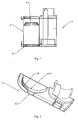
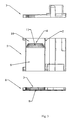
- Figure 1 is a sectioned view of the tank for ion exchange resins according to the present invention;
- Figure 2 is a perspective view of a part of the upper lid of the tank of Figure 1; and
- Figure 3 is a sectioned and exploded view of the tank for the ion exchange resins according to the present invention.
- Referring to Figure 1, the tank 1 for the ion exchange resins according to the present invention is provided with at least one entry conduit and an exit conduit for the feed water, not shown in the drawings, a body of the
tank 2, afirst filter 3 and asecond filter 4 for retaining the resins, placed upstream and downstream respectively of said body of thetank 2, in the direction of the flowing of the water. Advantageously, with reference to Figure 3, the tank 1 for the ion exchange resins consists of acentral member 5, alower lid 6 and anupper lid 7. Saidcentral member 5 is open above and below, and the body of thetank 2 and, at least partially, the channels for the entry and exit of the feed water are formed therein. Thecentral member 5 is closed below by thelower lid 6, which has various shoulders suitable for defining the external perimeter profile of saidlower lid 6 and at least saidfirst entry filter 3. Saidfirst entry filter 3 is more specifically composed of a shoulder of thelower lid 6 which has a closed profile corresponding to the section of the body of thetank 2 near the lower end of thecentral member 5 of the tank 1, said shoulder being formed by a series of appropriately distancedtoothed members 8. This distance between onetoothed member 8 and the next depends on the minimum size of the granules of ion exchange resins which the body of thetank 2 has to retain in its interior. The body of thetank 2 is formed integrally with and inside thecentral member 5, and consists of a hollow body, open above and below, inside whereof thesecond exit filter 4 is placed. Thesecond exit filter 4 is shaped like a lid and divides said body of thetank 2 into a first chamber for containing theresins 9, in the lower portion of said body of the tank, and into asecond guard chamber 10, in the upper portion of said body of thetank 2. Thesecond filter 4 is at least partially covered by a series ofopenings 11 whose distinctive dimension depends on the minimum size of the granules of ion exchange resins which said firstresins containing chamber 9 of the body of thetank 2 has to retain in its interior, and it is generally similar to the distance between twoconsecutive toothed members 8 of saidfirst entry filter 3. Thelower lid 6 closes below both thecentral member 5 by means of the aforementioned shoulder which defines the external profile of thelower lid 6, and the firstresins containing chamber 9 of the body of thetank 2 by means of the shoulder which defines saidfirst entry filter 3. This closure is made in a known manner via a hot blade welding procedure, although other equivalent procedures could be adopted. Thecentral member 5 will obviously be closed after the feeding, in the firstresins containing chamber 9 of the body of thetank 2, of a suitable volume of ion exchange resins, so that they remain confined there thanks to thefirst entry filter 3 and to thesecond exit filter 4. In a known manner these filters on the one hand allow the flowing of the feed water coming from the water supply system through the tank, and on the other hand retain the ion exchange resins inside the firstresins containing chamber 9 of the body of thetank 2. The tank 1 according to the present invention is also closed above by the upper lid 7 (Fig. 3), placed downstream of thesecond exit filter 4 in the direction of the flow of the feed water. Referring to Figures 2 and 3, theupper lid 7 has various shoulders designed to define theexternal perimeter profile 12 of saidupper lid 7 and at least thethird guard filter 13. Thisthird guard filter 13 is more specifically composed of a shoulder of theupper lid 7 which has a closed profile corresponding to the profile of thesecond guard chamber 10 near the upper end of thecentral member 5 of the tank 1, said shoulder being at least partially composed of a series of appropriately distancedtoothed members 14. This distance between onetoothed member 14 and the next depends on the minimum size of the granules of ion exchange resins which the tank 1 must not allow to exit, and is generally similar to the distance between two consecutivetoothed members 8 of saidfirst entry filter 3 and to the typical dimension of the series ofopenings 11 of thesecond exit filter 4. Theupper lid 7 closes thecentral member 5 above by means of the aforementioned shoulder which defines the external profile of theupper lid 7, and also closes thesecond guard chamber 10 of the body of thetank 2 by means of the shoulder which defines saidthird guard filter 13. This closure is achieved in a known manner via a hot blade welding procedure, although other equivalent procedures could be adopted. Advantageously the feed water that exits the firstresins containing chamber 9 traverses thesecond guard chamber 10 where it is filtered by thethird guard filter 13, before entering the exit channel of the tank 1. Thisthird filter 13 therefore forms a further and final barrier for those resin granules which could escape from thesecond exit filter 4 due to a possible breakage or malfunctioning of at least one of saidopenings 11 of thesecond filter 4. Advantageously the tank according to the present invention is composed of only three members, being it possible to make each one through a process of injection moulding of plastic resins and subsequently assemble them via known and economical processes such as hot blade welding. - The tank according to the present invention could be set up in a precisely overturned manner so as to have the filter upstream of the tank formed in the lid, the second filter formed in the body and the third formed in the base. Moreover it could comprise in its interior further functional members, such as for example the tank for the regenerating agent, without being it possible to alter in any way the general principle claimed below. The shape and the dimensions of the openings of the filters described, moreover, may undergo modifications that do not entail a change in the function of these components, and these modifications are therefore to be considered pertinent to the scope of protection as outlined herein below.
Claims (7)
- Tank (1) for ion exchange resins of the type comprising a body (2) of the tank (1), the channels for entry and exit of the feed water, a first entry filter (3) and a second exit filter (4) for retaining the resins upstream and downstream respectively of said body (2) of the tank (1), characterised in that it also comprises a third guard filter (13) positioned upstream of the channel for exit of the feed water from the tank (1) formed integral with said tank (1), suitable for retaining the resin granules that may have exited from the body (2) of the tank (1).
- Tank for ion exchange resins according to claim 1, wherein said tank (1) for the ion exchange resins consists of a central member (5), a lower lid (6)and an upper lid (7).
- Tank (1) for ion exchange resins according to the previous claims, wherein said third guard filter (13)consists of a shoulder of the upper lid (7) which has a closed profile corresponding to the profile of the body (2) of the tank (1) near the upper end of the central member (5) of said tank (1).
- Tank (1) for ion exchange resins according to the previous claims, wherein said shoulder of the upper lid (7) is at least partially composed of a series of appropriately distanced toothed members (14).
- Tank (1) for ion exchange resins according to the previous claims, wherein said second exit filter (4) is shaped as a lid, and divides said body (2) of the tank (1) into a first chamber (9) for containing resins in the lower portion of said body (2) of the tank (1), and into a second guard chamber (10) in the upper portion of said body (2) of the tank (1).
- Tank (1) for ion exchange resins according to the previous claims, wherein said first entry filter (3) is composed of a shoulder of the lower lid (6) which has a closed profile corresponding to the section of the body (2) of the tank (1)near the lower end of the central member (5) of the tank (1), said shoulder being formed by a series of appropriately distanced toothed members (8).
- Tank for ion exchange resins according to the previous claims, characterised in that it is composed of only three members (5, 6, 7), being it possible to produce each one via a process of injection moulding of plastic resins and to assemble these three members (5, 6, 7) subsequently by means of hot blade welding.
Priority Applications (1)
| Application Number | Priority Date | Filing Date | Title |
|---|---|---|---|
| PL07005989T PL1862105T3 (en) | 2006-05-30 | 2007-03-23 | Tank for ion exchange resins |
Applications Claiming Priority (1)
| Application Number | Priority Date | Filing Date | Title |
|---|---|---|---|
| IT000195U ITMI20060195U1 (en) | 2006-05-30 | 2006-05-30 | SERBATOPIO FOR ION EXCHANGE RESINS |
Publications (3)
| Publication Number | Publication Date |
|---|---|
| EP1862105A2 true EP1862105A2 (en) | 2007-12-05 |
| EP1862105A3 EP1862105A3 (en) | 2013-05-15 |
| EP1862105B1 EP1862105B1 (en) | 2015-01-21 |
Family
ID=38512472
Family Applications (1)
| Application Number | Title | Priority Date | Filing Date |
|---|---|---|---|
| EP07005989.4A Active EP1862105B1 (en) | 2006-05-30 | 2007-03-23 | Tank for ion exchange resins |
Country Status (3)
| Country | Link |
|---|---|
| EP (1) | EP1862105B1 (en) |
| IT (1) | ITMI20060195U1 (en) |
| PL (1) | PL1862105T3 (en) |
Family Cites Families (7)
| Publication number | Priority date | Publication date | Assignee | Title |
|---|---|---|---|---|
| YU33928B (en) * | 1972-07-22 | 1978-09-08 | Europe Mfg Trust | Device for softening water at dish washing machines and similar arrangements, on the basis of ion exchanging resin |
| US4090963A (en) * | 1975-09-15 | 1978-05-23 | Sta-Rite Industries, Inc. | Softening unit for appliance |
| DE4422709A1 (en) * | 1994-06-29 | 1996-01-04 | Sheco Ag | Water treatment unit |
| ITTO20010103A1 (en) * | 2001-02-05 | 2002-08-05 | T & P Spa | METHOD FOR DETECTING THE LACK OF A REGENERATING AGENT IN A WASHING MACHINE, IN PARTICULAR A DISHWASHER AND ITS S |
| WO2004101443A1 (en) * | 2003-05-19 | 2004-11-25 | Biechele Guenter | Device for softening water |
| DE102004002963A1 (en) * | 2003-06-27 | 2005-01-13 | Friedrich Sanner Gmbh & Co Kg Spritzgusswerk | Component made from a thermoplastic material for sieving machines has a sieving or grid structure formed by two groups of parallel ribs which extend over a partial region |
| JP4613125B2 (en) * | 2005-11-29 | 2011-01-12 | 株式会社Roki | Ion exchange filter |
-
2006
- 2006-05-30 IT IT000195U patent/ITMI20060195U1/en unknown
-
2007
- 2007-03-23 PL PL07005989T patent/PL1862105T3/en unknown
- 2007-03-23 EP EP07005989.4A patent/EP1862105B1/en active Active
Non-Patent Citations (1)
| Title |
|---|
| None |
Also Published As
| Publication number | Publication date |
|---|---|
| ITMI20060195U1 (en) | 2007-11-30 |
| PL1862105T3 (en) | 2015-06-30 |
| EP1862105A3 (en) | 2013-05-15 |
| EP1862105B1 (en) | 2015-01-21 |
Similar Documents
| Publication | Publication Date | Title |
|---|---|---|
| EP2345758B1 (en) | Hydraulic system for a laundry washing machine detergent dispenser | |
| EP2561790B1 (en) | Improved water-softening device | |
| US20150351605A1 (en) | System for supplying and treating water for a washing machine, in particular a dishwasher | |
| CN108138427B (en) | Hydraulic control and processing device, in particular for a hydraulic system or system | |
| US7566398B2 (en) | Water filtering device | |
| EP2988650B1 (en) | System for supplying and treating water for a dishwasher | |
| EP1862105B1 (en) | Tank for ion exchange resins | |
| ES2470415T3 (en) | Piston with built-in seals for a water softener control valve | |
| JP6719793B2 (en) | Water discharge head with water purification function, water purification cartridge and faucet device | |
| CN115006894B (en) | Drain head with water purification function, water purification filter element and faucet device | |
| JP2020142236A (en) | Water discharge head with water purification function, water purification cartridge and faucet device | |
| JP2019171382A (en) | Water discharge head with water purification function, water purification cartridge, and faucet device | |
| JP7818842B2 (en) | Water discharge head with water purification function, water purification cartridge and faucet device | |
| JP2021045756A (en) | Water discharge head with water purification function, water purification cartridge, and faucet device | |
| EP3054829B1 (en) | Dishwasher comprising a three-way valve | |
| JP2009178664A (en) | Water softening device and hot-water supply system | |
| EP0433676B1 (en) | Improvements to the water softening system in a washing machine | |
| CN114368801A (en) | Water softener assembly and dish washing machine with same | |
| KR200203209Y1 (en) | Soft water making device | |
| CN100503457C (en) | A floating bed switching device for water treatment softening valve | |
| EP1120080A2 (en) | A regulating device for decalcifying apparatus | |
| WO2017030962A1 (en) | Systems and methods for treatment of water for appliances | |
| KR20230100424A (en) | Water purifier | |
| KR101595237B1 (en) | silver-carbon filter assembly | |
| KR200362554Y1 (en) | Soft water making apparatus and body massage shower system having the same |
Legal Events
| Date | Code | Title | Description |
|---|---|---|---|
| PUAI | Public reference made under article 153(3) epc to a published international application that has entered the european phase |
Free format text: ORIGINAL CODE: 0009012 |
|
| AK | Designated contracting states |
Kind code of ref document: A2 Designated state(s): AT BE BG CH CY CZ DE DK EE ES FI FR GB GR HU IE IS IT LI LT LU LV MC MT NL PL PT RO SE SI SK TR |
|
| AX | Request for extension of the european patent |
Extension state: AL BA HR MK YU |
|
| PUAL | Search report despatched |
Free format text: ORIGINAL CODE: 0009013 |
|
| AK | Designated contracting states |
Kind code of ref document: A3 Designated state(s): AT BE BG CH CY CZ DE DK EE ES FI FR GB GR HU IE IS IT LI LT LU LV MC MT NL PL PT RO SE SI SK TR |
|
| AX | Request for extension of the european patent |
Extension state: AL BA HR MK RS |
|
| RIC1 | Information provided on ipc code assigned before grant |
Ipc: D06F 39/00 20060101ALI20130405BHEP Ipc: A47L 15/42 20060101AFI20130405BHEP |
|
| 17P | Request for examination filed |
Effective date: 20130917 |
|
| AKX | Designation fees paid |
Designated state(s): AT BE BG CH CY CZ DE DK EE ES FI FR GB GR HU IE IS IT LI LT LU LV MC MT NL PL PT RO SE SI SK TR |
|
| GRAP | Despatch of communication of intention to grant a patent |
Free format text: ORIGINAL CODE: EPIDOSNIGR1 |
|
| INTG | Intention to grant announced |
Effective date: 20140930 |
|
| GRAS | Grant fee paid |
Free format text: ORIGINAL CODE: EPIDOSNIGR3 |
|
| RAP1 | Party data changed (applicant data changed or rights of an application transferred) |
Owner name: T & P - S.P.A. |
|
| GRAA | (expected) grant |
Free format text: ORIGINAL CODE: 0009210 |
|
| RIN1 | Information on inventor provided before grant (corrected) |
Inventor name: GHINATO, RENZO |
|
| AK | Designated contracting states |
Kind code of ref document: B1 Designated state(s): AT BE BG CH CY CZ DE DK EE ES FI FR GB GR HU IE IS IT LI LT LU LV MC MT NL PL PT RO SE SI SK TR |
|
| REG | Reference to a national code |
Ref country code: GB Ref legal event code: FG4D |
|
| REG | Reference to a national code |
Ref country code: CH Ref legal event code: EP |
|
| REG | Reference to a national code |
Ref country code: IE Ref legal event code: FG4D |
|
| REG | Reference to a national code |
Ref country code: AT Ref legal event code: REF Ref document number: 707597 Country of ref document: AT Kind code of ref document: T Effective date: 20150215 |
|
| REG | Reference to a national code |
Ref country code: DE Ref legal event code: R096 Ref document number: 602007040093 Country of ref document: DE Effective date: 20150305 |
|
| REG | Reference to a national code |
Ref country code: NL Ref legal event code: VDEP Effective date: 20150121 |
|
| REG | Reference to a national code |
Ref country code: AT Ref legal event code: MK05 Ref document number: 707597 Country of ref document: AT Kind code of ref document: T Effective date: 20150121 |
|
| REG | Reference to a national code |
Ref country code: LT Ref legal event code: MG4D |
|
| REG | Reference to a national code |
Ref country code: PL Ref legal event code: T3 |
|
| PG25 | Lapsed in a contracting state [announced via postgrant information from national office to epo] |
Ref country code: SE Free format text: LAPSE BECAUSE OF FAILURE TO SUBMIT A TRANSLATION OF THE DESCRIPTION OR TO PAY THE FEE WITHIN THE PRESCRIBED TIME-LIMIT Effective date: 20150121 Ref country code: LT Free format text: LAPSE BECAUSE OF FAILURE TO SUBMIT A TRANSLATION OF THE DESCRIPTION OR TO PAY THE FEE WITHIN THE PRESCRIBED TIME-LIMIT Effective date: 20150121 Ref country code: FI Free format text: LAPSE BECAUSE OF FAILURE TO SUBMIT A TRANSLATION OF THE DESCRIPTION OR TO PAY THE FEE WITHIN THE PRESCRIBED TIME-LIMIT Effective date: 20150121 Ref country code: ES Free format text: LAPSE BECAUSE OF FAILURE TO SUBMIT A TRANSLATION OF THE DESCRIPTION OR TO PAY THE FEE WITHIN THE PRESCRIBED TIME-LIMIT Effective date: 20150121 Ref country code: BG Free format text: LAPSE BECAUSE OF FAILURE TO SUBMIT A TRANSLATION OF THE DESCRIPTION OR TO PAY THE FEE WITHIN THE PRESCRIBED TIME-LIMIT Effective date: 20150421 |
|
| PG25 | Lapsed in a contracting state [announced via postgrant information from national office to epo] |
Ref country code: AT Free format text: LAPSE BECAUSE OF FAILURE TO SUBMIT A TRANSLATION OF THE DESCRIPTION OR TO PAY THE FEE WITHIN THE PRESCRIBED TIME-LIMIT Effective date: 20150121 Ref country code: IS Free format text: LAPSE BECAUSE OF FAILURE TO SUBMIT A TRANSLATION OF THE DESCRIPTION OR TO PAY THE FEE WITHIN THE PRESCRIBED TIME-LIMIT Effective date: 20150521 Ref country code: NL Free format text: LAPSE BECAUSE OF FAILURE TO SUBMIT A TRANSLATION OF THE DESCRIPTION OR TO PAY THE FEE WITHIN THE PRESCRIBED TIME-LIMIT Effective date: 20150121 Ref country code: LV Free format text: LAPSE BECAUSE OF FAILURE TO SUBMIT A TRANSLATION OF THE DESCRIPTION OR TO PAY THE FEE WITHIN THE PRESCRIBED TIME-LIMIT Effective date: 20150121 Ref country code: GR Free format text: LAPSE BECAUSE OF FAILURE TO SUBMIT A TRANSLATION OF THE DESCRIPTION OR TO PAY THE FEE WITHIN THE PRESCRIBED TIME-LIMIT Effective date: 20150422 |
|
| REG | Reference to a national code |
Ref country code: DE Ref legal event code: R097 Ref document number: 602007040093 Country of ref document: DE |
|
| PG25 | Lapsed in a contracting state [announced via postgrant information from national office to epo] |
Ref country code: LU Free format text: LAPSE BECAUSE OF FAILURE TO SUBMIT A TRANSLATION OF THE DESCRIPTION OR TO PAY THE FEE WITHIN THE PRESCRIBED TIME-LIMIT Effective date: 20150323 Ref country code: MC Free format text: LAPSE BECAUSE OF FAILURE TO SUBMIT A TRANSLATION OF THE DESCRIPTION OR TO PAY THE FEE WITHIN THE PRESCRIBED TIME-LIMIT Effective date: 20150121 Ref country code: SK Free format text: LAPSE BECAUSE OF FAILURE TO SUBMIT A TRANSLATION OF THE DESCRIPTION OR TO PAY THE FEE WITHIN THE PRESCRIBED TIME-LIMIT Effective date: 20150121 Ref country code: DK Free format text: LAPSE BECAUSE OF FAILURE TO SUBMIT A TRANSLATION OF THE DESCRIPTION OR TO PAY THE FEE WITHIN THE PRESCRIBED TIME-LIMIT Effective date: 20150121 Ref country code: RO Free format text: LAPSE BECAUSE OF FAILURE TO SUBMIT A TRANSLATION OF THE DESCRIPTION OR TO PAY THE FEE WITHIN THE PRESCRIBED TIME-LIMIT Effective date: 20150121 Ref country code: EE Free format text: LAPSE BECAUSE OF FAILURE TO SUBMIT A TRANSLATION OF THE DESCRIPTION OR TO PAY THE FEE WITHIN THE PRESCRIBED TIME-LIMIT Effective date: 20150121 Ref country code: CZ Free format text: LAPSE BECAUSE OF FAILURE TO SUBMIT A TRANSLATION OF THE DESCRIPTION OR TO PAY THE FEE WITHIN THE PRESCRIBED TIME-LIMIT Effective date: 20150121 |
|
| REG | Reference to a national code |
Ref country code: CH Ref legal event code: PL |
|
| PLBE | No opposition filed within time limit |
Free format text: ORIGINAL CODE: 0009261 |
|
| STAA | Information on the status of an ep patent application or granted ep patent |
Free format text: STATUS: NO OPPOSITION FILED WITHIN TIME LIMIT |
|
| GBPC | Gb: european patent ceased through non-payment of renewal fee |
Effective date: 20150421 |
|
| 26N | No opposition filed |
Effective date: 20151022 |
|
| REG | Reference to a national code |
Ref country code: FR Ref legal event code: ST Effective date: 20151130 |
|
| REG | Reference to a national code |
Ref country code: IE Ref legal event code: MM4A |
|
| PG25 | Lapsed in a contracting state [announced via postgrant information from national office to epo] |
Ref country code: CH Free format text: LAPSE BECAUSE OF NON-PAYMENT OF DUE FEES Effective date: 20150331 Ref country code: IE Free format text: LAPSE BECAUSE OF NON-PAYMENT OF DUE FEES Effective date: 20150323 Ref country code: LI Free format text: LAPSE BECAUSE OF NON-PAYMENT OF DUE FEES Effective date: 20150331 Ref country code: GB Free format text: LAPSE BECAUSE OF NON-PAYMENT OF DUE FEES Effective date: 20150421 |
|
| PG25 | Lapsed in a contracting state [announced via postgrant information from national office to epo] |
Ref country code: SI Free format text: LAPSE BECAUSE OF FAILURE TO SUBMIT A TRANSLATION OF THE DESCRIPTION OR TO PAY THE FEE WITHIN THE PRESCRIBED TIME-LIMIT Effective date: 20150121 Ref country code: FR Free format text: LAPSE BECAUSE OF NON-PAYMENT OF DUE FEES Effective date: 20150331 |
|
| PG25 | Lapsed in a contracting state [announced via postgrant information from national office to epo] |
Ref country code: BE Free format text: LAPSE BECAUSE OF FAILURE TO SUBMIT A TRANSLATION OF THE DESCRIPTION OR TO PAY THE FEE WITHIN THE PRESCRIBED TIME-LIMIT Effective date: 20150121 |
|
| REG | Reference to a national code |
Ref country code: DE Ref legal event code: R082 Ref document number: 602007040093 Country of ref document: DE Representative=s name: LERMERRAIBLE PATENT- U. RECHTSANWALTS PARTGMBB, DE |
|
| PG25 | Lapsed in a contracting state [announced via postgrant information from national office to epo] |
Ref country code: MT Free format text: LAPSE BECAUSE OF FAILURE TO SUBMIT A TRANSLATION OF THE DESCRIPTION OR TO PAY THE FEE WITHIN THE PRESCRIBED TIME-LIMIT Effective date: 20150121 |
|
| PG25 | Lapsed in a contracting state [announced via postgrant information from national office to epo] |
Ref country code: HU Free format text: LAPSE BECAUSE OF FAILURE TO SUBMIT A TRANSLATION OF THE DESCRIPTION OR TO PAY THE FEE WITHIN THE PRESCRIBED TIME-LIMIT; INVALID AB INITIO Effective date: 20070323 |
|
| PG25 | Lapsed in a contracting state [announced via postgrant information from national office to epo] |
Ref country code: CY Free format text: LAPSE BECAUSE OF FAILURE TO SUBMIT A TRANSLATION OF THE DESCRIPTION OR TO PAY THE FEE WITHIN THE PRESCRIBED TIME-LIMIT Effective date: 20150121 |
|
| PG25 | Lapsed in a contracting state [announced via postgrant information from national office to epo] |
Ref country code: PT Free format text: LAPSE BECAUSE OF FAILURE TO SUBMIT A TRANSLATION OF THE DESCRIPTION OR TO PAY THE FEE WITHIN THE PRESCRIBED TIME-LIMIT Effective date: 20150521 |
|
| P01 | Opt-out of the competence of the unified patent court (upc) registered |
Effective date: 20230323 |
|
| PGFP | Annual fee paid to national office [announced via postgrant information from national office to epo] |
Ref country code: DE Payment date: 20260325 Year of fee payment: 20 |
|
| PGFP | Annual fee paid to national office [announced via postgrant information from national office to epo] |
Ref country code: IT Payment date: 20260325 Year of fee payment: 20 |
|
| PGFP | Annual fee paid to national office [announced via postgrant information from national office to epo] |
Ref country code: TR Payment date: 20260319 Year of fee payment: 20 |
|
| PGFP | Annual fee paid to national office [announced via postgrant information from national office to epo] |
Ref country code: PL Payment date: 20260318 Year of fee payment: 20 |