EP1862034B1 - Electro-acoustic transducer - Google Patents
Electro-acoustic transducer Download PDFInfo
- Publication number
- EP1862034B1 EP1862034B1 EP06709961A EP06709961A EP1862034B1 EP 1862034 B1 EP1862034 B1 EP 1862034B1 EP 06709961 A EP06709961 A EP 06709961A EP 06709961 A EP06709961 A EP 06709961A EP 1862034 B1 EP1862034 B1 EP 1862034B1
- Authority
- EP
- European Patent Office
- Prior art keywords
- transducer
- front part
- transducer according
- reinforcing
- supporting part
- Prior art date
- Legal status (The legal status is an assumption and is not a legal conclusion. Google has not performed a legal analysis and makes no representation as to the accuracy of the status listed.)
- Expired - Lifetime
Links
Images


Classifications
-
- H—ELECTRICITY
- H04—ELECTRIC COMMUNICATION TECHNIQUE
- H04R—LOUDSPEAKERS, MICROPHONES, GRAMOPHONE PICK-UPS OR LIKE ACOUSTIC ELECTROMECHANICAL TRANSDUCERS; ELECTRIC HEARING AIDS; PUBLIC ADDRESS SYSTEMS
- H04R7/00—Diaphragms for electromechanical transducers; Cones
- H04R7/02—Diaphragms for electromechanical transducers; Cones characterised by the construction
- H04R7/12—Non-planar diaphragms or cones
- H04R7/127—Non-planar diaphragms or cones dome-shaped
-
- H—ELECTRICITY
- H04—ELECTRIC COMMUNICATION TECHNIQUE
- H04R—LOUDSPEAKERS, MICROPHONES, GRAMOPHONE PICK-UPS OR LIKE ACOUSTIC ELECTROMECHANICAL TRANSDUCERS; ELECTRIC HEARING AIDS; PUBLIC ADDRESS SYSTEMS
- H04R7/00—Diaphragms for electromechanical transducers; Cones
- H04R7/16—Mounting or tensioning of diaphragms or cones
- H04R7/18—Mounting or tensioning of diaphragms or cones at the periphery
-
- H—ELECTRICITY
- H04—ELECTRIC COMMUNICATION TECHNIQUE
- H04R—LOUDSPEAKERS, MICROPHONES, GRAMOPHONE PICK-UPS OR LIKE ACOUSTIC ELECTROMECHANICAL TRANSDUCERS; ELECTRIC HEARING AIDS; PUBLIC ADDRESS SYSTEMS
- H04R9/00—Transducers of moving-coil, moving-strip, or moving-wire type
- H04R9/02—Details
- H04R9/04—Construction, mounting, or centering of coil
- H04R9/041—Centering
Definitions
- the present invention relates to electro-acoustic transducers, and especially to such transducers for use in loudspeakers.
- the invention particularly relates to dome-shaped transducers, for example high frequency transducers commonly referred to as "tweeters”.
- Rigid (“hard”) dome-shaped electro-acoustic transducers arranged to radiate high frequency acoustic waves (for example above about 15 kHz) have been used in loudspeakers for many years. It is fundamental to their ideal functioning that such hard dome-shaped transducers are substantially rigid (such that they exhibit minimal flexing during use) and have a low mass (such that the maximum proportion of input power is converted to acoustic output power). These twin objectives have hitherto been achieved by a combination of the inherent structural rigidity of the dome shape, and the use of low density materials, including plastics materials, low density metals and metal alloys, ceramics and composite materials.
- dome-shaped electro-acoustic transducers include those disclosed by United States Patent Nos. 4,531,608 and 6,757,404 B2 , among many others.
- the present invention seeks to provide an improved electro-acoustic transducer that is able to combine the twin properties of high rigidity and low mass while being less constrained In its shape than hitherto.
- JP 60-171897 discloses a diaphragm for a speaker in which a coupling cone extends from engagement with a voice coil bobbin to engagement with a composite diaphragm having a central dome.
- the upper part of the voice coil bobbin is connected to the outer circumference of the dome.
- a first aspect of the invention provides an electro-acoustic transducer, comprising a front part having an acoustically radiating surface, a supporting part that supports the front part and that extends from a peripheral region of the front part in a direction away from the acoustically radiating surface, and a reinforcing part that provides rigidity to the transducer, wherein the reinforcing part extends from the supporting part to the front part such that a portion of the reinforcing part is spaced from the front part and the supporting part, wherein at least the portion of the reinforcing part that is spaced from the front part and the supporting part is substantially in the shape of a truncated dome.
- the invention has the advantages that by providing a reinforcing part to the transducer extending between the supporting part and the front part, yet spaced from the front part and the supporting part, the transducer can be made with high rigidity and low mass while providing a great deal of technical design freedom in the shape of the acoustically radiating surface. Consequently, the invention provides a radical departure from known dome-shaped transducers by substantially avoiding the need for the acoustically radiating part of the transducer to provide the required rigidity by means of its shape. Instead, the shape of the acoustically radiating part of the transducer according to the invention can be determined primarily, or (preferably) substantially entirely, by acoustic rather than mechanical considerations.
- a portion of the reinforcing part is spaced from both the front part and the supporting part.
- the reinforcing part is situated behind the front part of the transducer.
- the supporting part extends substantially from the periphery of the front part.
- the periphery of the front part preferably is substantially circular.
- the supporting part may be substantially cylindrical.
- the truncated dome of the reinforcing part may have a substantially spherical or substantially spheroid curvature.
- at least the portion of the reinforcing part that is spaced from the front part and the supporting part may be substantially in the shape of a truncated cone, for example.
- the reinforcing part may be substantially continuous, e.g. around an axis of the transducer.
- the reinforcing part may comprise a plurality of sections, e.g. spaced apart from each other. Such sections may comprise reinforcing struts, for example.
- the reinforcing part may be perforated or porous, for example.
- the reinforcing part and/or the supporting part and/or the front part is/are formed from one or more sheets of material.
- the front part of the transducer is dome-shaped.
- the acoustically radiating surface of the front part is dome-shaped, and most preferably has substantially the shape of a segment of a sphere.
- a radius, or a minimum radius, of the acoustically radiating surface of the front part is greater than a radius, or a maximum radius, of at least the portion of the reinforcing part that is spaced from the front part and the supporting part.
- the reinforcing part of the transducer that is spaced apart from the front part and the supporting part is so spaced by a maximum of 5 mm, more preferably a maximum of 3 mm, even more preferably a maximum of 1 mm, especially a maximum of 0.5 mm, e.g. a maximum of 0.3 mm.
- the acoustically radiating surface of the transducer according to the invention has a diameter of at least 10 mm, more preferably at least 15 mm, e.g. approximately 19 mm.
- the acoustically radiating surface of the transducer has a diameter of no greater than 120 mm, preferably no greater than 100 mm, more preferably no greater than 80 mm, even more preferably no greater than 60 mm, especially no greater than 40 mm.
- the dome-shaped transducer preferably is formed from a substantially rigid low density material, for example a metal or metal alloy material, a composite material, a carbon fibre material, a plastics material, or a ceramic material.
- a metal or metal alloy material for example titanium; aluminium; and beryllium.
- the acoustically radiating surface of the dome-shaped transducer may be formed from a specialist material, for example diamond (especially chemically deposited diamond).
- a second aspect of the invention provides a loudspeaker comprising at least one transducer according to the first aspect of the invention.
- the loudspeaker may include one or more further transducers and/or one or more acoustically radiating diaphragms, for example.
- a third aspect of the invention provides a loudspeaker system comprising a plurality of loudspeakers according to the second aspect of the invention.
- a drive unit 15 of the dome-shaped transducer 7 comprises a pot 17, a disc-shaped magnet 19 and a disc-shaped inner pole 21.
- the pot 17 is substantially cylindrical and has an opening 23 to receive the disc-shaped magnet 19 and the inner pole 21.
- the opening 23 is defined by a radially-inwardly extending lip 25 that forms an outer pole of the drive unit 15.
- a substantially cylindrical supporting part (or former) 27 of the dome-shaped transducer 7 carries a coil 29 of an electrical conductor (e.g. a wire) that is wound around the supporting part 27.
- the coil 29 and supporting part 27 extend between the inner and outer poles 21 and 25 of the drive unit.
- the dome-shaped transducer 7 is driven substantially along the axis 12 by the drive unit, and is stabilized by the surround 13.
- a flexible web part (or seal part) 31 of the surround permits the axial movement of the transducer 7.
- Preferably at least an outer 50% of the radial width of the web part 31 of the surround 13 is overlapped
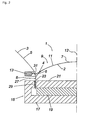
- FIG. 2 shows part of the electro-acoustic transducer 7 in detail.
- the transducer 7 comprises a front part 2 having an acoustically radiating surface 11, a supporting part (or former) 27 that supports the front part and that extends from a peripheral region 4 of the front part in a direction away from the acoustically radiating surface, and a reinforcing part 6 that provides rigidity to the transducer.
- the reinforcing part 6 extends from the supporting part 27 to the front part 2 such that a portion of the reinforcing part is spaced from the front part and the supporting part by a gap 8.
- the rigidity provided to the transducer 7 by the reinforcing part 6 provides a great degree of design freedom in the shape of the acoustically-radiating surface 11, so that the surface may be designed substantially entirely to acoustic criteria rather than mechanical criteria. Also, the fact that a portion of the reinforcing part is spaced from the front part 2 and the supporting part 27 means that the reinforcing part can be low in mass, thereby contributing only minimal inertial mass to the transducer (which is advantageous because the lower the mass of the transducer 7 the greater proportion of applied electrical power is converted to acoustic power).
- the reinforcing part (or at least the portion spaced from the supporting part and the front part of the transducer) comprises a thin sheet of material.
- the reinforcing part preferably comprises a sheet of material having substantially the same thickness as the material from which the front part and/or the supporting part of the transducer preferably is/are formed.
- the reinforcing part may be thicker or thinner than the material from which the front part and/or the supporting part of the transducer is/are formed.
- the reinforcing part may be formed from the same material as the front part and/or the supporting part, or it may be formed from a different material.
- the reinforcing part may be formed from carbon fibre material.
- the reinforcing part comprises a truncated dome that extends between the supporting part and the front part of the transducer.
- the reinforcing part transfers forces between the supporting part and the front part of the transducer in a progressive manner.
- Figure 3 shows a graphical representation of sound pressure level (in dB) versus sound frequency (in Hz) modelled on computer by finite element analysis for a reinforced transducer according to the invention compared to that for a transducer having the same shape of acoustically radiating surface but not reinforced (and thus falling outside the scope of the invention).
- the structure of the computer-modelled transducer according to the invention was as shown in Figure 2 .
- the structure of the computer-modelled non-reinforced transducer was the same as that shown in Figure 2 except that the reinforcing part 6 was omitted.
- the operating frequency range will normally be from about 5kHz to about 20 kHz (or possibly higher; for Super Audio Compact Disc (SACD) systems, for example, the operating frequency range extends above 20 kHz). It is therefore desired for transducers according to the invention to have a sound pressure level response over this frequency range that is as constant ("flat") as possible.
- Figure 3 clearly shows that the modelled reinforced transducer according to the invention exhibited a significantly flatter sound pressure level response than did the non-reinforced transducer, particularly over the frequency range from 10 kHz to 20 kHz (which is the most important range for high frequency transducers, i.e. "tweeters"). Consequently, the reinforced transducer according to the invention demonstrates a clear acoustic advantage over non-reinforced transducers.
Landscapes
- Engineering & Computer Science (AREA)
- Multimedia (AREA)
- Physics & Mathematics (AREA)
- Acoustics & Sound (AREA)
- Signal Processing (AREA)
- Diaphragms For Electromechanical Transducers (AREA)
- Audible-Bandwidth Dynamoelectric Transducers Other Than Pickups (AREA)
- Obtaining Desirable Characteristics In Audible-Bandwidth Transducers (AREA)
- Piezo-Electric Transducers For Audible Bands (AREA)
Description
- The present invention relates to electro-acoustic transducers, and especially to such transducers for use in loudspeakers. The invention particularly relates to dome-shaped transducers, for example high frequency transducers commonly referred to as "tweeters".
- Rigid ("hard") dome-shaped electro-acoustic transducers arranged to radiate high frequency acoustic waves (for example above about 15 kHz) have been used in loudspeakers for many years. It is fundamental to their ideal functioning that such hard dome-shaped transducers are substantially rigid (such that they exhibit minimal flexing during use) and have a low mass (such that the maximum proportion of input power is converted to acoustic output power). These twin objectives have hitherto been achieved by a combination of the inherent structural rigidity of the dome shape, and the use of low density materials, including plastics materials, low density metals and metal alloys, ceramics and composite materials.
- Specific examples of the huge number of known dome-shaped electro-acoustic transducers include those disclosed by United States Patent Nos.
4,531,608 and6,757,404 B2 , among many others. - The present invention seeks to provide an improved electro-acoustic transducer that is able to combine the twin properties of high rigidity and low mass while being less constrained In its shape than hitherto.
-
JP 60-171897 - Accordingly, a first aspect of the invention provides an electro-acoustic transducer, comprising a front part having an acoustically radiating surface, a supporting part that supports the front part and that extends from a peripheral region of the front part in a direction away from the acoustically radiating surface, and a reinforcing part that provides rigidity to the transducer, wherein the reinforcing part extends from the supporting part to the front part such that a portion of the reinforcing part is spaced from the front part and the supporting part, wherein at least the portion of the reinforcing part that is spaced from the front part and the supporting part is substantially in the shape of a truncated dome.
- The invention has the advantages that by providing a reinforcing part to the transducer extending between the supporting part and the front part, yet spaced from the front part and the supporting part, the transducer can be made with high rigidity and low mass while providing a great deal of technical design freedom in the shape of the acoustically radiating surface. Consequently, the invention provides a radical departure from known dome-shaped transducers by substantially avoiding the need for the acoustically radiating part of the transducer to provide the required rigidity by means of its shape. Instead, the shape of the acoustically radiating part of the transducer according to the invention can be determined primarily, or (preferably) substantially entirely, by acoustic rather than mechanical considerations.
- In preferred embodiments of the invention, a portion of the reinforcing part is spaced from both the front part and the supporting part. The reinforcing part is situated behind the front part of the transducer.
- Preferably the supporting part extends substantially from the periphery of the front part. The periphery of the front part preferably is substantially circular. Advantageously, the supporting part may be substantially cylindrical.
- Advantageously, the truncated dome of the reinforcing part may have a substantially spherical or substantially spheroid curvature. Alternatively, at least the portion of the reinforcing part that is spaced from the front part and the supporting part may be substantially in the shape of a truncated cone, for example. The reinforcing part may be substantially continuous, e.g. around an axis of the transducer. Alternatively, the reinforcing part may comprise a plurality of sections, e.g. spaced apart from each other. Such sections may comprise reinforcing struts, for example. The reinforcing part may be perforated or porous, for example.
- Preferably the reinforcing part and/or the supporting part and/or the front part is/are formed from one or more sheets of material.
- In preferred embodiments of the invention, the front part of the transducer is dome-shaped. Preferably the acoustically radiating surface of the front part is dome-shaped, and most preferably has substantially the shape of a segment of a sphere.
- Preferably, a radius, or a minimum radius, of the acoustically radiating surface of the front part is greater than a radius, or a maximum radius, of at least the portion of the reinforcing part that is spaced from the front part and the supporting part.
- In at least some preferred embodiments of the invention, the reinforcing part of the transducer that is spaced apart from the front part and the supporting part, is so spaced by a maximum of 5 mm, more preferably a maximum of 3 mm, even more preferably a maximum of 1 mm, especially a maximum of 0.5 mm, e.g. a maximum of 0.3 mm.
- Preferably the acoustically radiating surface of the transducer according to the invention has a diameter of at least 10 mm, more preferably at least 15 mm, e.g. approximately 19 mm. Preferably the acoustically radiating surface of the transducer has a diameter of no greater than 120 mm, preferably no greater than 100 mm, more preferably no greater than 80 mm, even more preferably no greater than 60 mm, especially no greater than 40 mm.
- The dome-shaped transducer preferably is formed from a substantially rigid low density material, for example a metal or metal alloy material, a composite material, a carbon fibre material, a plastics material, or a ceramic material. Some preferred metals for forming a suitable metal or metal alloy material include: titanium; aluminium; and beryllium. The acoustically radiating surface of the dome-shaped transducer may be formed from a specialist material, for example diamond (especially chemically deposited diamond).
- A second aspect of the invention provides a loudspeaker comprising at least one transducer according to the first aspect of the invention. The loudspeaker may include one or more further transducers and/or one or more acoustically radiating diaphragms, for example.
- A third aspect of the invention provides a loudspeaker system comprising a plurality of loudspeakers according to the second aspect of the invention.
- Other preferred and optional features of the invention are described below and in the dependent claims.
- An example of a preferred embodiment of the invention will now be described, by way of example, with reference to the accompanying drawings, of which:
-
Figure 1 shows, schematically and in cross-section, part of a loudspeaker incorporating an electro-acoustic transducer according to the invention; -
Figure 2 shows a detail ofFigure 1 , illustrating in particular an electro-acoustic transducer according to the invention; and -
Figure 3 shows a graphical representation of sound pressure level (in dB) versus sound frequency (in Hz) modelled for a reinforced transducer according to' the invention compared to that for a transducer having the same shape of acoustically radiating surface but not reinforced (and thus falling outside the scope of the invention). -
Figures 1 and2 show, schematically and in cross-section, part of a loudspeaker 1 according to the present invention. (Both figures show only one half of the loudspeaker on one side of alongitudinal axis 12. The loudspeaker is symmetrical about the axis.) The loudspeaker 1 comprises ahorn waveguide 3 having awaveguide surface 5, and a convex dome-shaped transducer 7 according to the embodiment of the invention located generally in the throat 9 of the horn waveguide. The convex dome-shaped transducer 7 has a substantially rigid acousticallyradiating surface 11, which preferably is shaped substantially as a segment of a sphere (i.e. the curvature of thesurface 11 is a substantially spherical curvature). The transducer 7 includes a reinforcing part 6, which is shown inFigure 2 , but for clarity is not shown inFigure 1 . Thehorn waveguide 3 is a generally frusto-conical flared static waveguide having alongitudinal axis 12. Asurround 13 of the dome-shaped transducer 7 is attached to thehorn waveguide 3 behind the throat 9. - A
drive unit 15 of the dome-shaped transducer 7 comprises apot 17, a disc-shaped magnet 19 and a disc-shapedinner pole 21. Thepot 17 is substantially cylindrical and has an opening 23 to receive the disc-shaped magnet 19 and theinner pole 21. The opening 23 is defined by a radially-inwardly extending lip 25 that forms an outer pole of thedrive unit 15. A substantially cylindrical supporting part (or former) 27 of the dome-shaped transducer 7 carries acoil 29 of an electrical conductor (e.g. a wire) that is wound around the supportingpart 27. Thecoil 29 and supportingpart 27 extend between the inner andouter poles 21 and 25 of the drive unit. The dome-shaped transducer 7 is driven substantially along theaxis 12 by the drive unit, and is stabilized by thesurround 13. A flexible web part (or seal part) 31 of the surround permits the axial movement of the transducer 7. Preferably at least an outer 50% of the radial width of theweb part 31 of thesurround 13 is overlapped by the throat 9 of the horn waveguide. -
Figure 2 shows part of the electro-acoustic transducer 7 in detail. The transducer 7 comprises afront part 2 having an acousticallyradiating surface 11, a supporting part (or former) 27 that supports the front part and that extends from aperipheral region 4 of the front part in a direction away from the acoustically radiating surface, and a reinforcing part 6 that provides rigidity to the transducer. The reinforcing part 6 extends from the supportingpart 27 to thefront part 2 such that a portion of the reinforcing part is spaced from the front part and the supporting part by agap 8. The rigidity provided to the transducer 7 by the reinforcing part 6 provides a great degree of design freedom in the shape of the acoustically-radiatingsurface 11, so that the surface may be designed substantially entirely to acoustic criteria rather than mechanical criteria. Also, the fact that a portion of the reinforcing part is spaced from thefront part 2 and the supportingpart 27 means that the reinforcing part can be low in mass, thereby contributing only minimal inertial mass to the transducer (which is advantageous because the lower the mass of the transducer 7 the greater proportion of applied electrical power is converted to acoustic power). - Preferably, as illustrated, the reinforcing part (or at least the portion spaced from the supporting part and the front part of the transducer) comprises a thin sheet of material. The reinforcing part preferably comprises a sheet of material having substantially the same thickness as the material from which the front part and/or the supporting part of the transducer preferably is/are formed. Alternatively, however, the reinforcing part may be thicker or thinner than the material from which the front part and/or the supporting part of the transducer is/are formed. Also, the reinforcing part may be formed from the same material as the front part and/or the supporting part, or it may be formed from a different material. For example, the reinforcing part may be formed from carbon fibre material. As illustrated, the reinforcing part comprises a truncated dome that extends between the supporting part and the front part of the transducer. Advantageously, the reinforcing part transfers forces between the supporting part and the front part of the transducer in a progressive manner.
-
Figure 3 shows a graphical representation of sound pressure level (in dB) versus sound frequency (in Hz) modelled on computer by finite element analysis for a reinforced transducer according to the invention compared to that for a transducer having the same shape of acoustically radiating surface but not reinforced (and thus falling outside the scope of the invention). The structure of the computer-modelled transducer according to the invention was as shown inFigure 2 . The structure of the computer-modelled non-reinforced transducer was the same as that shown inFigure 2 except that the reinforcing part 6 was omitted. - As the skilled person knows, in order for an electro-acoustic transducer to perform adequately it is necessary for the sound pressure level of sounds produced by the transducer to be as constant as practicable (for a given input power) over substantially the entire operating sound frequency range of the transducer. For preferred transducers according to the invention, the operating frequency range will normally be from about 5kHz to about 20 kHz (or possibly higher; for Super Audio Compact Disc (SACD) systems, for example, the operating frequency range extends above 20 kHz). It is therefore desired for transducers according to the invention to have a sound pressure level response over this frequency range that is as constant ("flat") as possible.
-
Figure 3 clearly shows that the modelled reinforced transducer according to the invention exhibited a significantly flatter sound pressure level response than did the non-reinforced transducer, particularly over the frequency range from 10 kHz to 20 kHz (which is the most important range for high frequency transducers, i.e. "tweeters"). Consequently, the reinforced transducer according to the invention demonstrates a clear acoustic advantage over non-reinforced transducers.
Claims (20)
- An electro-acoustic transducer (7), comprising a front part (2) having an acoustically radiating surface (11), a supporting part (27) that supports the front part and that extends from a peripheral region (4) of the front part in a direction away from the acoustically radiating surface, and a reinforcing part (6) that provides rigidity to the transducer by extending from the supporting part to the front part such that a portion of the reinforcing part is spaced from the front part and the supporting part, wherein at least the portion of the reinforcing part that is spaced from the front part and the supporting part is substantially in the shape of a truncated dome.
- A transducer according to Claim 1, in which the supporting part extends substantially from the periphery of the front part.
- A transducer according to any preceding claim, in which the periphery of the front part Is substantially circular.
- A transducer according to any preceding claim, in which the supporting part is substantially cylindrical.
- A transducer according to Claim 1, In which the truncated dome of the reinforcing part has a substantially spherical curvature.
- A transducer according to any preceding claim, in which at least the portion of the reinforcing part that is spaced from the front part and the supporting part is substantially continuous.
- A transducer according to any preceding claim, in which the reinforcing part and/or the supporting part and/or the front part is/are formed from one or more sheets of material.
- A transducer according to any one of Claims 1 to 6, in which at least the portion of the reinforcing part that is spaced from the front part and the supporting part comprises a plurality of sections.
- A transducer according to Claim 8, in which at least some of the sections are spaced apart from each other.
- A transducer according to Claim 8 or Claim 9, in which the sections comprise reinforcing struts.
- A transducer according to any preceding claim, in which the reinforcing part Is perforated.
- A transducer according to any preceding claim, in which the front part is dome-shaped.
- A transducer according to any preceding claim, in which the acoustically radiating surface of the front part is dome-shaped.
- A transducer according to any preceding claim, in which the acoustically radiating surface of the front part has substantially the shape of a segment of a sphere.
- A transducer according to Claim 13 or 14, in which a radius, or a minimum radius, of the acoustically radiating surface of the front part is greater than a radius, or a maximum radius, of at least the portion of the reinforcing part that is spaced from the front part and the supporting part.
- A transducer according to any preceding claim, further comprising a coiled electrical conductor carried by the supporting part.
- A transducer according to any preceding claim, further comprising a magnet forming part of a drive unit for the transducer.
- A loudspeaker (1) comprising at least one transducer (7) according to any preceding claim.
- A loudspeaker according to Claim 18, including one or more further transducers and/or one or more acoustically radiating diaphragms.
- A loudspeaker system comprising a plurality of loudspeakers according to Claim 18 or Claim 19.
Applications Claiming Priority (2)
| Application Number | Priority Date | Filing Date | Title |
|---|---|---|---|
| GB0504274A GB2426884B (en) | 2005-03-02 | 2005-03-02 | Electro-acoustic transducer |
| PCT/GB2006/000737 WO2006092596A1 (en) | 2005-03-02 | 2006-03-02 | Electro-acoustic transducer |
Publications (2)
| Publication Number | Publication Date |
|---|---|
| EP1862034A1 EP1862034A1 (en) | 2007-12-05 |
| EP1862034B1 true EP1862034B1 (en) | 2012-12-05 |
Family
ID=34430481
Family Applications (1)
| Application Number | Title | Priority Date | Filing Date |
|---|---|---|---|
| EP06709961A Expired - Lifetime EP1862034B1 (en) | 2005-03-02 | 2006-03-02 | Electro-acoustic transducer |
Country Status (7)
| Country | Link |
|---|---|
| US (1) | US8320605B2 (en) |
| EP (1) | EP1862034B1 (en) |
| JP (1) | JP2008532403A (en) |
| CN (1) | CN101185372B (en) |
| GB (1) | GB2426884B (en) |
| TW (1) | TW200701820A (en) |
| WO (1) | WO2006092596A1 (en) |
Families Citing this family (3)
| Publication number | Priority date | Publication date | Assignee | Title |
|---|---|---|---|---|
| GB2449842B (en) * | 2007-05-03 | 2012-02-01 | Pss Belgium Nv | Loudspeaker with a stiffening element |
| CN101651915B (en) * | 2008-08-13 | 2013-07-24 | 宏达国际电子股份有限公司 | Electronic device and its electroacoustic transducer |
| GB2474853B (en) * | 2009-10-27 | 2014-01-01 | Gp Acoustics Uk Ltd | Loudspeakers |
Family Cites Families (27)
| Publication number | Priority date | Publication date | Assignee | Title |
|---|---|---|---|---|
| US3119888A (en) * | 1954-07-06 | 1964-01-28 | Dukane Corp | Method of making a transducer diaphragm |
| JPS50144426A (en) * | 1974-05-09 | 1975-11-20 | ||
| JPS5423892Y2 (en) * | 1974-09-28 | 1979-08-15 | ||
| JPS5357022A (en) | 1976-11-02 | 1978-05-24 | Kenzou Inoue | Movable coil acoustic transducer vibrator plate |
| FR2428952A3 (en) * | 1978-04-03 | 1980-01-11 | Audax | Hi=Fi loudspeaker having convex diaphragm - rigidly secured to loudspeaker coil former and flexibly secured to outer annular pole piece |
| DE3018659A1 (en) * | 1980-05-16 | 1981-11-26 | Friedrich-Wilhelm Dr. Bracht | Loudspeaker diaphragm composed of shells - has first shell connected to other shell without full surface contact |
| US4531608A (en) * | 1982-10-29 | 1985-07-30 | Heinz Harro K | High frequency compression driver |
| US4590332A (en) * | 1983-05-23 | 1986-05-20 | Pascal Delbuck | Phase coherent low frequency speaker |
| JPS60171897A (en) | 1984-02-16 | 1985-09-05 | Matsushita Electric Ind Co Ltd | Diaphragm for speaker |
| US5548657A (en) | 1988-05-09 | 1996-08-20 | Kef Audio (Uk) Limited | Compound loudspeaker drive unit |
| JPH02238798A (en) | 1989-03-13 | 1990-09-21 | Jusaburo Sudo | Speaker system |
| JP3116119B2 (en) | 1989-04-27 | 2000-12-11 | ティーオーエー株式会社 | Horn for speaker |
| GB2261135A (en) | 1991-11-02 | 1993-05-05 | Meir Mordechai | A loudspeaker |
| CN2250001Y (en) * | 1993-04-01 | 1997-03-19 | 李代繁 | Whole frequency spectrum single-body electricity-sound transducer |
| JPH07154896A (en) * | 1993-11-29 | 1995-06-16 | Matsushita Electric Ind Co Ltd | Speaker |
| JPH08163694A (en) * | 1994-11-30 | 1996-06-21 | Mitsubishi Electric Corp | Integrated speaker diaphragm |
| JPH08168092A (en) * | 1994-12-13 | 1996-06-25 | Mitsubishi Electric Corp | speaker |
| JPH09135489A (en) * | 1995-08-24 | 1997-05-20 | Mutsuo Kubo | Coaxial speaker and coaxial all horn speaker |
| IT1285103B1 (en) | 1996-04-02 | 1998-06-03 | Paolo Agostinelli | ELECTROACOUSTIC DIFFUSION DEVICE, WITH DIAPHRAGM, CENTERING AND HORNS IN BALSA WOOD OR ITS MIXTURE. |
| JPH1042389A (en) * | 1996-07-26 | 1998-02-13 | Fujitsu Ten Ltd | Thin speaker |
| ATE388601T1 (en) * | 2000-01-27 | 2008-03-15 | Nxp Bv | ELECTROACOUSTIC TRANSDUCER HAVING A MEMBRANE WITH COIL MOUNTING PROJECTIONS AND INTERMEDIATE STABILIZING WALLS |
| GB2364847B (en) | 2000-07-11 | 2004-10-13 | Kef Audio | Compound loudspeaker having a magnet system |
| CA2352732A1 (en) | 2000-07-11 | 2002-01-11 | Philip Jeffrey Anthony | Compound loudspeaker drive unit having a magnet system |
| JP4557412B2 (en) | 2000-11-20 | 2010-10-06 | パナソニック株式会社 | Speaker |
| GB2371165B (en) | 2001-01-16 | 2004-12-22 | Kh Technology | Magnet system for loudspeakers |
| GB2377849A (en) | 2001-07-21 | 2003-01-22 | Kh Technology Corp | Loudspeaker drive units with smooth transition to surround |
| JP3651470B2 (en) * | 2003-03-31 | 2005-05-25 | 松下電器産業株式会社 | Speaker |
-
2005
- 2005-03-02 GB GB0504274A patent/GB2426884B/en not_active Expired - Lifetime
-
2006
- 2006-03-02 WO PCT/GB2006/000737 patent/WO2006092596A1/en not_active Ceased
- 2006-03-02 EP EP06709961A patent/EP1862034B1/en not_active Expired - Lifetime
- 2006-03-02 US US11/885,612 patent/US8320605B2/en active Active
- 2006-03-02 CN CN2006800137718A patent/CN101185372B/en not_active Expired - Lifetime
- 2006-03-02 JP JP2007557585A patent/JP2008532403A/en active Pending
- 2006-03-02 TW TW095107011A patent/TW200701820A/en unknown
Also Published As
| Publication number | Publication date |
|---|---|
| GB2426884B (en) | 2008-05-28 |
| GB0504274D0 (en) | 2005-04-06 |
| US20090022356A1 (en) | 2009-01-22 |
| US8320605B2 (en) | 2012-11-27 |
| CN101185372A (en) | 2008-05-21 |
| WO2006092596A1 (en) | 2006-09-08 |
| EP1862034A1 (en) | 2007-12-05 |
| CN101185372B (en) | 2012-02-01 |
| JP2008532403A (en) | 2008-08-14 |
| GB2426884A (en) | 2006-12-06 |
| TW200701820A (en) | 2007-01-01 |
| HK1118415A1 (en) | 2009-02-06 |
Similar Documents
| Publication | Publication Date | Title |
|---|---|---|
| EP2008495B1 (en) | Phase plug | |
| HK1052817A1 (en) | Flat panel sound radiator with supported exciter and compliant surround | |
| EP2321976A1 (en) | Nested compound loudspeaker drive unit | |
| US20060215870A1 (en) | Low profile speaker and system | |
| EP1856945B1 (en) | Loudspeaker | |
| US8320605B2 (en) | Electro-acoustic transducer | |
| US20030121718A1 (en) | Diaphragm suspension assembly for loudspeaker transducers | |
| EP1757160B1 (en) | Diamond diaphragms for loudspeaker drive units or microphones | |
| US6792127B1 (en) | Elliptical dome for high frequency transducer | |
| WO2001037607A2 (en) | Offset apex spider | |
| JP2003158795A (en) | Piezoelectric speaker | |
| JP2007243659A (en) | Voice coil bobbin, and speaker unit | |
| US12069459B2 (en) | Loudspeaker assembly with a separate voice coil assembly | |
| HK1118415B (en) | Electro-acoustic transducer | |
| EP1096830A2 (en) | High frequency transducer | |
| JP3201096B2 (en) | Horn speaker | |
| US20080219481A1 (en) | Loudspeaker Having a Movable Cone Body | |
| JP2844846B2 (en) | Horn type speaker | |
| JPH10108294A (en) | Double dome diaphragm and speaker using the same | |
| GB1591184A (en) | Electroacoustic transducers | |
| JP2004112283A (en) | Distributed loudspeaker system | |
| JP2589802B2 (en) | Dome speaker | |
| JP2002171598A (en) | Tweeter | |
| JP2003304594A (en) | Treble speaker | |
| HK1126614B (en) | Phase plug |
Legal Events
| Date | Code | Title | Description |
|---|---|---|---|
| PUAI | Public reference made under article 153(3) epc to a published international application that has entered the european phase |
Free format text: ORIGINAL CODE: 0009012 |
|
| 17P | Request for examination filed |
Effective date: 20070926 |
|
| AK | Designated contracting states |
Kind code of ref document: A1 Designated state(s): AT BE BG CH CY CZ DE DK EE ES FI FR GB GR HU IE IS IT LI LT LU LV MC NL PL PT RO SE SI SK TR |
|
| DAX | Request for extension of the european patent (deleted) | ||
| 17Q | First examination report despatched |
Effective date: 20100806 |
|
| GRAP | Despatch of communication of intention to grant a patent |
Free format text: ORIGINAL CODE: EPIDOSNIGR1 |
|
| RIC1 | Information provided on ipc code assigned before grant |
Ipc: H04R 7/18 20060101ALI20110823BHEP Ipc: H04R 7/12 20060101AFI20110823BHEP |
|
| GRAS | Grant fee paid |
Free format text: ORIGINAL CODE: EPIDOSNIGR3 |
|
| GRAA | (expected) grant |
Free format text: ORIGINAL CODE: 0009210 |
|
| AK | Designated contracting states |
Kind code of ref document: B1 Designated state(s): AT BE BG CH CY CZ DE DK EE ES FI FR GB GR HU IE IS IT LI LT LU LV MC NL PL PT RO SE SI SK TR |
|
| REG | Reference to a national code |
Ref country code: GB Ref legal event code: FG4D Ref country code: DE Ref legal event code: R081 Ref document number: 602006033450 Country of ref document: DE Owner name: KEF CELESTION CORPORATION, GEORGE TOWN, KY Free format text: FORMER OWNER: KH TECHNOLOGY CORP., GEORGE TOWN, GRAND CAYMAN, KY |
|
| REG | Reference to a national code |
Ref country code: CH Ref legal event code: EP |
|
| REG | Reference to a national code |
Ref country code: AT Ref legal event code: REF Ref document number: 587842 Country of ref document: AT Kind code of ref document: T Effective date: 20121215 |
|
| REG | Reference to a national code |
Ref country code: IE Ref legal event code: FG4D |
|
| REG | Reference to a national code |
Ref country code: DE Ref legal event code: R096 Ref document number: 602006033450 Country of ref document: DE Effective date: 20130131 |
|
| REG | Reference to a national code |
Ref country code: AT Ref legal event code: MK05 Ref document number: 587842 Country of ref document: AT Kind code of ref document: T Effective date: 20121205 |
|
| PG25 | Lapsed in a contracting state [announced via postgrant information from national office to epo] |
Ref country code: ES Free format text: LAPSE BECAUSE OF FAILURE TO SUBMIT A TRANSLATION OF THE DESCRIPTION OR TO PAY THE FEE WITHIN THE PRESCRIBED TIME-LIMIT Effective date: 20130316 Ref country code: LT Free format text: LAPSE BECAUSE OF FAILURE TO SUBMIT A TRANSLATION OF THE DESCRIPTION OR TO PAY THE FEE WITHIN THE PRESCRIBED TIME-LIMIT Effective date: 20121205 Ref country code: SE Free format text: LAPSE BECAUSE OF FAILURE TO SUBMIT A TRANSLATION OF THE DESCRIPTION OR TO PAY THE FEE WITHIN THE PRESCRIBED TIME-LIMIT Effective date: 20121205 Ref country code: FI Free format text: LAPSE BECAUSE OF FAILURE TO SUBMIT A TRANSLATION OF THE DESCRIPTION OR TO PAY THE FEE WITHIN THE PRESCRIBED TIME-LIMIT Effective date: 20121205 |
|
| REG | Reference to a national code |
Ref country code: NL Ref legal event code: VDEP Effective date: 20121205 |
|
| REG | Reference to a national code |
Ref country code: LT Ref legal event code: MG4D |
|
| PG25 | Lapsed in a contracting state [announced via postgrant information from national office to epo] |
Ref country code: SI Free format text: LAPSE BECAUSE OF FAILURE TO SUBMIT A TRANSLATION OF THE DESCRIPTION OR TO PAY THE FEE WITHIN THE PRESCRIBED TIME-LIMIT Effective date: 20121205 Ref country code: LV Free format text: LAPSE BECAUSE OF FAILURE TO SUBMIT A TRANSLATION OF THE DESCRIPTION OR TO PAY THE FEE WITHIN THE PRESCRIBED TIME-LIMIT Effective date: 20121205 Ref country code: GR Free format text: LAPSE BECAUSE OF FAILURE TO SUBMIT A TRANSLATION OF THE DESCRIPTION OR TO PAY THE FEE WITHIN THE PRESCRIBED TIME-LIMIT Effective date: 20130306 Ref country code: PL Free format text: LAPSE BECAUSE OF FAILURE TO SUBMIT A TRANSLATION OF THE DESCRIPTION OR TO PAY THE FEE WITHIN THE PRESCRIBED TIME-LIMIT Effective date: 20121205 |
|
| PG25 | Lapsed in a contracting state [announced via postgrant information from national office to epo] |
Ref country code: AT Free format text: LAPSE BECAUSE OF FAILURE TO SUBMIT A TRANSLATION OF THE DESCRIPTION OR TO PAY THE FEE WITHIN THE PRESCRIBED TIME-LIMIT Effective date: 20121205 |
|
| PG25 | Lapsed in a contracting state [announced via postgrant information from national office to epo] |
Ref country code: IS Free format text: LAPSE BECAUSE OF FAILURE TO SUBMIT A TRANSLATION OF THE DESCRIPTION OR TO PAY THE FEE WITHIN THE PRESCRIBED TIME-LIMIT Effective date: 20130405 Ref country code: BE Free format text: LAPSE BECAUSE OF FAILURE TO SUBMIT A TRANSLATION OF THE DESCRIPTION OR TO PAY THE FEE WITHIN THE PRESCRIBED TIME-LIMIT Effective date: 20121205 Ref country code: EE Free format text: LAPSE BECAUSE OF FAILURE TO SUBMIT A TRANSLATION OF THE DESCRIPTION OR TO PAY THE FEE WITHIN THE PRESCRIBED TIME-LIMIT Effective date: 20121205 Ref country code: SK Free format text: LAPSE BECAUSE OF FAILURE TO SUBMIT A TRANSLATION OF THE DESCRIPTION OR TO PAY THE FEE WITHIN THE PRESCRIBED TIME-LIMIT Effective date: 20121205 Ref country code: BG Free format text: LAPSE BECAUSE OF FAILURE TO SUBMIT A TRANSLATION OF THE DESCRIPTION OR TO PAY THE FEE WITHIN THE PRESCRIBED TIME-LIMIT Effective date: 20130305 Ref country code: CZ Free format text: LAPSE BECAUSE OF FAILURE TO SUBMIT A TRANSLATION OF THE DESCRIPTION OR TO PAY THE FEE WITHIN THE PRESCRIBED TIME-LIMIT Effective date: 20121205 |
|
| PG25 | Lapsed in a contracting state [announced via postgrant information from national office to epo] |
Ref country code: NL Free format text: LAPSE BECAUSE OF FAILURE TO SUBMIT A TRANSLATION OF THE DESCRIPTION OR TO PAY THE FEE WITHIN THE PRESCRIBED TIME-LIMIT Effective date: 20121205 Ref country code: RO Free format text: LAPSE BECAUSE OF FAILURE TO SUBMIT A TRANSLATION OF THE DESCRIPTION OR TO PAY THE FEE WITHIN THE PRESCRIBED TIME-LIMIT Effective date: 20121205 Ref country code: PT Free format text: LAPSE BECAUSE OF FAILURE TO SUBMIT A TRANSLATION OF THE DESCRIPTION OR TO PAY THE FEE WITHIN THE PRESCRIBED TIME-LIMIT Effective date: 20130405 |
|
| PLBE | No opposition filed within time limit |
Free format text: ORIGINAL CODE: 0009261 |
|
| STAA | Information on the status of an ep patent application or granted ep patent |
Free format text: STATUS: NO OPPOSITION FILED WITHIN TIME LIMIT |
|
| PG25 | Lapsed in a contracting state [announced via postgrant information from national office to epo] |
Ref country code: DK Free format text: LAPSE BECAUSE OF FAILURE TO SUBMIT A TRANSLATION OF THE DESCRIPTION OR TO PAY THE FEE WITHIN THE PRESCRIBED TIME-LIMIT Effective date: 20121205 Ref country code: MC Free format text: LAPSE BECAUSE OF NON-PAYMENT OF DUE FEES Effective date: 20130331 |
|
| REG | Reference to a national code |
Ref country code: CH Ref legal event code: PL |
|
| 26N | No opposition filed |
Effective date: 20130906 |
|
| PG25 | Lapsed in a contracting state [announced via postgrant information from national office to epo] |
Ref country code: CY Free format text: LAPSE BECAUSE OF FAILURE TO SUBMIT A TRANSLATION OF THE DESCRIPTION OR TO PAY THE FEE WITHIN THE PRESCRIBED TIME-LIMIT Effective date: 20121205 |
|
| PG25 | Lapsed in a contracting state [announced via postgrant information from national office to epo] |
Ref country code: IT Free format text: LAPSE BECAUSE OF FAILURE TO SUBMIT A TRANSLATION OF THE DESCRIPTION OR TO PAY THE FEE WITHIN THE PRESCRIBED TIME-LIMIT Effective date: 20121205 |
|
| REG | Reference to a national code |
Ref country code: IE Ref legal event code: MM4A |
|
| REG | Reference to a national code |
Ref country code: DE Ref legal event code: R097 Ref document number: 602006033450 Country of ref document: DE Effective date: 20130906 |
|
| PG25 | Lapsed in a contracting state [announced via postgrant information from national office to epo] |
Ref country code: CH Free format text: LAPSE BECAUSE OF NON-PAYMENT OF DUE FEES Effective date: 20130331 Ref country code: LI Free format text: LAPSE BECAUSE OF NON-PAYMENT OF DUE FEES Effective date: 20130331 Ref country code: IE Free format text: LAPSE BECAUSE OF NON-PAYMENT OF DUE FEES Effective date: 20130302 |
|
| PG25 | Lapsed in a contracting state [announced via postgrant information from national office to epo] |
Ref country code: TR Free format text: LAPSE BECAUSE OF FAILURE TO SUBMIT A TRANSLATION OF THE DESCRIPTION OR TO PAY THE FEE WITHIN THE PRESCRIBED TIME-LIMIT Effective date: 20121205 |
|
| PG25 | Lapsed in a contracting state [announced via postgrant information from national office to epo] |
Ref country code: HU Free format text: LAPSE BECAUSE OF FAILURE TO SUBMIT A TRANSLATION OF THE DESCRIPTION OR TO PAY THE FEE WITHIN THE PRESCRIBED TIME-LIMIT; INVALID AB INITIO Effective date: 20060302 Ref country code: LU Free format text: LAPSE BECAUSE OF NON-PAYMENT OF DUE FEES Effective date: 20130302 |
|
| REG | Reference to a national code |
Ref country code: FR Ref legal event code: PLFP Year of fee payment: 11 |
|
| REG | Reference to a national code |
Ref country code: FR Ref legal event code: CD Owner name: KEF CELESTION CORPORATION, KY Effective date: 20160513 |
|
| REG | Reference to a national code |
Ref country code: DE Ref legal event code: R082 Ref document number: 602006033450 Country of ref document: DE Representative=s name: ZENZ PATENTANWAELTE PARTNERSCHAFT MBB, DE Ref country code: DE Ref legal event code: R081 Ref document number: 602006033450 Country of ref document: DE Owner name: KEF CELESTION CORPORATION, GEORGE TOWN, KY Free format text: FORMER OWNER: KH TECHNOLOGY CORP., GRAND CAYMAN, KY |
|
| REG | Reference to a national code |
Ref country code: FR Ref legal event code: PLFP Year of fee payment: 12 |
|
| REG | Reference to a national code |
Ref country code: FR Ref legal event code: PLFP Year of fee payment: 13 |
|
| PGFP | Annual fee paid to national office [announced via postgrant information from national office to epo] |
Ref country code: DE Payment date: 20250331 Year of fee payment: 20 |
|
| PGFP | Annual fee paid to national office [announced via postgrant information from national office to epo] |
Ref country code: FR Payment date: 20250212 Year of fee payment: 20 |
|
| PGFP | Annual fee paid to national office [announced via postgrant information from national office to epo] |
Ref country code: GB Payment date: 20250110 Year of fee payment: 20 |
|
| REG | Reference to a national code |
Ref country code: DE Ref legal event code: R071 Ref document number: 602006033450 Country of ref document: DE |
|
| REG | Reference to a national code |
Ref country code: GB Ref legal event code: PE20 Expiry date: 20260301 |