EP1861588B1 - Electric turbo compound configuration for an engine/electric generator system - Google Patents
Electric turbo compound configuration for an engine/electric generator system Download PDFInfo
- Publication number
- EP1861588B1 EP1861588B1 EP06736155.0A EP06736155A EP1861588B1 EP 1861588 B1 EP1861588 B1 EP 1861588B1 EP 06736155 A EP06736155 A EP 06736155A EP 1861588 B1 EP1861588 B1 EP 1861588B1
- Authority
- EP
- European Patent Office
- Prior art keywords
- engine
- turbine
- electric
- electric generator
- power
- Prior art date
- Legal status (The legal status is an assumption and is not a legal conclusion. Google has not performed a legal analysis and makes no representation as to the accuracy of the status listed.)
- Revoked
Links
Images
Classifications
-
- F—MECHANICAL ENGINEERING; LIGHTING; HEATING; WEAPONS; BLASTING
- F02—COMBUSTION ENGINES; HOT-GAS OR COMBUSTION-PRODUCT ENGINE PLANTS
- F02B—INTERNAL-COMBUSTION PISTON ENGINES; COMBUSTION ENGINES IN GENERAL
- F02B37/00—Engines characterised by provision of pumps driven at least for part of the time by exhaust
- F02B37/12—Control of the pumps
- F02B37/18—Control of the pumps by bypassing exhaust from the inlet to the outlet of turbine or to the atmosphere
-
- F—MECHANICAL ENGINEERING; LIGHTING; HEATING; WEAPONS; BLASTING
- F02—COMBUSTION ENGINES; HOT-GAS OR COMBUSTION-PRODUCT ENGINE PLANTS
- F02G—HOT GAS OR COMBUSTION-PRODUCT POSITIVE-DISPLACEMENT ENGINE PLANTS; USE OF WASTE HEAT OF COMBUSTION ENGINES; NOT OTHERWISE PROVIDED FOR
- F02G5/00—Profiting from waste heat of combustion engines, not otherwise provided for
- F02G5/02—Profiting from waste heat of exhaust gases
-
- H—ELECTRICITY
- H02—GENERATION; CONVERSION OR DISTRIBUTION OF ELECTRIC POWER
- H02J—ELECTRIC POWER NETWORKS; CIRCUIT ARRANGEMENTS OR SYSTEMS FOR SUPPLYING OR DISTRIBUTING ELECTRIC POWER; SYSTEMS FOR STORING ELECTRIC ENERGY
- H02J3/00—Circuit arrangements for AC mains or AC distribution networks
- H02J3/38—Arrangements for feeding a single network from two or more generators or sources in parallel; Arrangements for feeding already energised networks from additional generators or sources in parallel
-
- H—ELECTRICITY
- H02—GENERATION; CONVERSION OR DISTRIBUTION OF ELECTRIC POWER
- H02K—DYNAMO-ELECTRIC MACHINES
- H02K7/00—Arrangements for handling mechanical energy structurally associated with dynamo-electric machines, e.g. structural association with mechanical driving motors or auxiliary dynamo-electric machines
- H02K7/18—Structural association of electric generators with mechanical driving motors, e.g. with turbines
- H02K7/1807—Rotary generators
- H02K7/1815—Rotary generators structurally associated with reciprocating piston engines
-
- Y—GENERAL TAGGING OF NEW TECHNOLOGICAL DEVELOPMENTS; GENERAL TAGGING OF CROSS-SECTIONAL TECHNOLOGIES SPANNING OVER SEVERAL SECTIONS OF THE IPC; TECHNICAL SUBJECTS COVERED BY FORMER USPC CROSS-REFERENCE ART COLLECTIONS [XRACs] AND DIGESTS
- Y02—TECHNOLOGIES OR APPLICATIONS FOR MITIGATION OR ADAPTATION AGAINST CLIMATE CHANGE
- Y02T—CLIMATE CHANGE MITIGATION TECHNOLOGIES RELATED TO TRANSPORTATION
- Y02T10/00—Road transport of goods or passengers
- Y02T10/10—Internal combustion engine [ICE] based vehicles
- Y02T10/12—Improving ICE efficiencies
Definitions
- the present invention relates to an engine-powered electric generation system.
- Gen sets typically include a diesel engine driving an AC generator via a mechanical shaft.
- the engine is normally isochronized governor controlled.
- the generator is connected to supply electrical power to an AC power grid. All power delivered to the generator must be delivered through the engine output shaft. Thus, all components must be sized to handle the peak output of the generator.
- an object of this invention is to increase the total electrical power output of an engine/generator system without increasing the size of the engine size.
- an engine/electric generator system includes an internal combustion engine, and a primary electric generator which is driven by an output shaft of the engine and which provides electrical power to an electric power AC transmission line.
- the system includes a turbocharger having a first turbine driven by exhaust gasses from the engine and a compressor driven by the first turbine and providing inlet air to the engine.
- An exhaust line communicates exhaust gas from the first turbine to an inlet of a secondary turbine.
- a secondary electric generator is driven by the secondary turbine.
- the electrical power output of the secondary electric generator is combined with the power generated by the primary electric generator and delivered to an AC transmission line. This increases net efficiency of the system and increases the total output of the generator system.
- An engine/electric generator system may comprise an internal combustion engine; a primary electric generator driven by an output shaft of the engine and providing electrical power, the primary electric generator providing electrical power to a transmission line; a turbocharger having a first turbine driven by exhaust gasses from the engine and a compressor driven by the first turbine and providing inlet air to the engine; a secondary turbine; an exhaust line communicating exhaust gas from the first turbine to an input of the secondary turbine; a secondary electric generator driven by the secondary turbine; and a rectifier/AC inverter receiving electric power from the secondary electric generator, and delivering electric power to the transmission line.
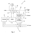
- an engine/electric generator system 10 includes an internal combustion engine 12, such as a Diesel engine and a primary conventional electric generator 14 driven by the output shaft 16 of the engine 12.
- the generator outputs electrical power on a set of electrical transmission lines 18.
- the engine/electric generator system 10 of Fig. 1 is preferably a common generator configuration with a "genset" engine using constant speed governor control.
- a turbocharger 20 includes a first turbine 22 driven by exhaust gasses from the engine 12 and a compressor 24 driven by the first turbine 20 and providing inlet air to the engine 12.
- An exhaust line 30 communicates exhaust gas from the first turbine 22 to a secondary turbine 32.
- a secondary electric generator or "turbo-generator” 34 is driven by the secondary turbine 32.
- the secondary generator 34 is preferably a high speed alternator.
- the secondary generator 34 provides electrical power to a rectifier/AC inverter 36.
- the rectifier/AC inverter 36 converts the electrical power from the generator 34 to a form or frequency which matches the power generated by generator 14 and transmits it onto the transmission lines 18.
- the turbo-generator supplies rectified DC that is converted directly into AC power.
- An exhaust gas recirculation line 40 communicates an output of the first turbine 22 to an input of the compressor 24, and a valve 42 in the exhaust gas recirculation line 40 controls the flow of exhaust gas recirculation therethrough.
- a waste gate line 44 communicates the exhaust line 30 and the output of the first turbine 22 to the output of the secondary turbine 32, and a valve 46 in line 44 controls the flow of exhaust gas therethrough.
- a control unit (not shown) could be adapted to control valves 42 and 44 to control the output of the secondary turbine 32 as desired.
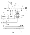
- Fig. 2 there is shown a "genset" configuration wherein the engine has a non-synchronous control (not shown) were the output of the primary generator is rectified to DC and combined with the Turbo Generator DC on a common DC bus, then rectified into AC power.
- the generator 14 provides 3-phase electrical power to an electrical unit 50 which includes a rectifier 52, a DC bus 54 and an AC inverter 56.
- Bus 54 connects the rectifier 52 to the inverter 56.
- the secondary turbine 32 drives a high speed alternator or "turbo-generator” 60 which provides 3-phase electric power to a rectifier 62.
- Rectifier 62 provides DC power to the DC bus 54 so that the combined power from rectifiers 52 and 62 is supplied to AC inverter 56, and so that the combined power is supplied to the transmission line 18.
- the AC inverter then provides AC electrical power on lines 18.
- the output of the turbo-generator is combined with the output of the engine powered generator. This permits maximization of power output for a given engine size, and optimization of total system efficiency.
Landscapes
- Engineering & Computer Science (AREA)
- Chemical & Material Sciences (AREA)
- Combustion & Propulsion (AREA)
- Mechanical Engineering (AREA)
- General Engineering & Computer Science (AREA)
- Power Engineering (AREA)
- Supercharger (AREA)
- Control Of Eletrric Generators (AREA)
- Exhaust-Gas Circulating Devices (AREA)
Description
- The present invention relates to an engine-powered electric generation system.
- Traditional engine-powered electric generation systems ("gen sets") typically include a diesel engine driving an AC generator via a mechanical shaft. The engine is normally isochronized governor controlled. The generator is connected to supply electrical power to an AC power grid. All power delivered to the generator must be delivered through the engine output shaft. Thus, all components must be sized to handle the peak output of the generator.
- It would be desirable to improve the fuel economy and operating costs of such an engine/generator system. It is also desirable to use the smallest possible engine in such a system in order to reduce product cost.
- Accordingly, an object of this invention is to increase the total electrical power output of an engine/generator system without increasing the size of the engine size.
- This and other objects are achieved by the present invention, wherein an engine/electric generator system includes an internal combustion engine, and a primary electric generator which is driven by an output shaft of the engine and which provides electrical power to an electric power AC transmission line. The system includes a turbocharger having a first turbine driven by exhaust gasses from the engine and a compressor driven by the first turbine and providing inlet air to the engine. An exhaust line communicates exhaust gas from the first turbine to an inlet of a secondary turbine. A secondary electric generator is driven by the secondary turbine. The electrical power output of the secondary electric generator is combined with the power generated by the primary electric generator and delivered to an AC transmission line. This increases net efficiency of the system and increases the total output of the generator system.
- An engine/electric generator system may comprise an internal combustion engine; a primary electric generator driven by an output shaft of the engine and providing electrical power, the primary electric generator providing electrical power to a transmission line; a turbocharger having a first turbine driven by exhaust gasses from the engine and a compressor driven by the first turbine and providing inlet air to the engine; a secondary turbine; an exhaust line communicating exhaust gas from the first turbine to an input of the secondary turbine; a secondary electric generator driven by the secondary turbine; and a rectifier/AC inverter receiving electric power from the secondary electric generator, and delivering electric power to the transmission line.
-
-
Fig. 1 is a simplified schematic diagram of an engine/electric generator system according to the present invention; and -
Fig. 2 is a simplified schematic diagram of an alternate embodiment of the present invention. - Referring to
Fig. 1 , an engine/electric generator system 10 includes aninternal combustion engine 12, such as a Diesel engine and a primary conventionalelectric generator 14 driven by theoutput shaft 16 of theengine 12. The generator outputs electrical power on a set ofelectrical transmission lines 18. The engine/electric generator system 10 ofFig. 1 is preferably a common generator configuration with a "genset" engine using constant speed governor control. - A
turbocharger 20 includes afirst turbine 22 driven by exhaust gasses from theengine 12 and acompressor 24 driven by thefirst turbine 20 and providing inlet air to theengine 12. - An
exhaust line 30 communicates exhaust gas from thefirst turbine 22 to asecondary turbine 32. A secondary electric generator or "turbo-generator" 34 is driven by thesecondary turbine 32. Thesecondary generator 34 is preferably a high speed alternator. Thesecondary generator 34 provides electrical power to a rectifier/AC inverter 36. The rectifier/AC inverter 36 converts the electrical power from thegenerator 34 to a form or frequency which matches the power generated bygenerator 14 and transmits it onto thetransmission lines 18. As a result, with the system ofFig. 1 , the turbo-generator supplies rectified DC that is converted directly into AC power. - An exhaust
gas recirculation line 40 communicates an output of thefirst turbine 22 to an input of thecompressor 24, and avalve 42 in the exhaustgas recirculation line 40 controls the flow of exhaust gas recirculation therethrough. - A
waste gate line 44 communicates theexhaust line 30 and the output of thefirst turbine 22 to the output of thesecondary turbine 32, and avalve 46 inline 44 controls the flow of exhaust gas therethrough. A control unit (not shown) could be adapted tocontrol valves secondary turbine 32 as desired. - Referring now to
Fig. 2 , there is shown a "genset" configuration wherein the engine has a non-synchronous control (not shown) were the output of the primary generator is rectified to DC and combined with the Turbo Generator DC on a common DC bus, then rectified into AC power. In theFig. 2 embodiment thegenerator 14 provides 3-phase electrical power to anelectrical unit 50 which includes arectifier 52, aDC bus 54 and anAC inverter 56.Bus 54 connects therectifier 52 to theinverter 56. - The
secondary turbine 32 drives a high speed alternator or "turbo-generator" 60 which provides 3-phase electric power to arectifier 62. Rectifier 62 provides DC power to theDC bus 54 so that the combined power fromrectifiers AC inverter 56, and so that the combined power is supplied to thetransmission line 18. - The AC inverter then provides AC electrical power on
lines 18. - With this system exhaust energy is converted into electric power and placed on the electric power transmission lines independent of a mechanical connection with the engine shaft. This increases the total electrical power output, without increasing the size of the engine size, thus improving fuel efficiency. For a given generator output, a reduced engine size may be achieved. In other words, in the system of
Fig. 2 the output of theprimary generator 14 is rectified to DC and combined with the DC power from the turbo-generator 60 on a common DC bus, then rectified or converted into AC power. - Thus, with the systems of both
Fig. 1 andFig. 2 , the output of the turbo-generator is combined with the output of the engine powered generator. This permits maximization of power output for a given engine size, and optimization of total system efficiency.
Claims (9)
- An engine/electric generator system (10), comprising:an internal combustion engine (12);a primary electric generator (14) driven by an output shaft (16) of the engine (12) and providing electrical power;a turbocharger (20) having a first turbine (22) driven by exhaust gasses from the engine (12) and a compressor (24) driven by the first turbine (20) and providing inlet air to the engine (12);a secondary turbine (32);an exhaust line (30) communicating exhaust gas from the first turbine (22) to an input of the secondary turbine (32);a secondary electric generator (34) driven by the secondary turbine (32); andelectric power combining circuit for combining electric power from the primary electric generator (14) and the secondary electric generator (34), and delivering combined electric power to a transmission line (18).
- The engine/electric generator system of claim 1, wherein:the primary electric generator (14) provides electrical power to the transmission line (18); andthe electric power combining circuit comprises a rectifier/AC inverter (36) receiving electric power from the secondary electric generator (34), and delivering electric power to the transmission line (18). (fig. 1)
- The engine/electric generator system of claim 1, wherein:a primary rectifier (52) receives AC electric power from the primary generator (14);
the secondary generator (60) comprises a high speed alternator which generates AC electrical power;
a secondary rectifier (62) receives AC electric power from the alternator (60); a DC bus (54) receives DC power from the primary and secondary rectifiers (52, 62); and
an AC inverter (56) receives DC electrical power from the DC bus (54) and provides AC electric power to the transmission line (18). - The engine/electric generator system of claim 1, wherein:the secondary electric generator (34) comprises a high speed alternator (60).
- The engine/electric generator system of claim 1, further comprising:an exhaust gas recirculation line (40) communicating an output of the first turbine (22) to an input of the compressor (24).
- The engine/electric generator system of claim 5, further comprising:a valve (42) in the exhaust gas recirculation line (40) controlling flow of gasses therethrough.
- The engine/electric generator system of claim 1, further comprising:a waste gate line (44) communicating the exhaust line (30) to an output of the secondary turbine (32).
- The engine/electric generator system of claim 7, further comprising:a valve (46) in the waste gate line (44) for controlling flow of gasses therethrough.
- An engine/electric generator system (10), comprising:an internal combustion engine (12);a primary electric generator (14) driven by an output shaft (16) of the engine (12) and providing electrical power;a primary rectifier (52) receiving AC electric power from the primary generator (14);a turbocharger (20) having a first turbine (14) driven by exhaust gasses from the engine (12) and a compressor (24) driven by the first turbine (14) and providing inlet air to the engine (12);a secondary turbine (32);an exhaust line (30) communicating exhaust gas from the first turbine (14) to an input of the secondary turbine (32);a high speed alternator (60) driven by the secondary turbine (32), the alternator (60) generating AC electrical power;a secondary rectifier (62) receiving AC electric power from the alternator (60);a DC bus (54) receiving and combining DC power from the primary and secondary rectifiers (52, 62); andan AC inverter (56) receiving DC electrical power from the DC bus (54) and providing AC electric power to a transmission line (18).
Applications Claiming Priority (2)
| Application Number | Priority Date | Filing Date | Title |
|---|---|---|---|
| US11/079,804 US7047743B1 (en) | 2005-03-14 | 2005-03-14 | Electric turbo compound configuration for an engine/electric generator system |
| PCT/US2006/006776 WO2006098866A1 (en) | 2005-03-14 | 2006-02-27 | Electric turbo compound configuration for an engine/electric generator system |
Publications (2)
| Publication Number | Publication Date |
|---|---|
| EP1861588A1 EP1861588A1 (en) | 2007-12-05 |
| EP1861588B1 true EP1861588B1 (en) | 2014-06-25 |
Family
ID=36423653
Family Applications (1)
| Application Number | Title | Priority Date | Filing Date |
|---|---|---|---|
| EP06736155.0A Revoked EP1861588B1 (en) | 2005-03-14 | 2006-02-27 | Electric turbo compound configuration for an engine/electric generator system |
Country Status (10)
| Country | Link |
|---|---|
| US (1) | US7047743B1 (en) |
| EP (1) | EP1861588B1 (en) |
| JP (1) | JP2008533383A (en) |
| CN (1) | CN100591894C (en) |
| AR (1) | AR053166A1 (en) |
| AU (1) | AU2006223558A1 (en) |
| BR (1) | BRPI0609011A2 (en) |
| MX (1) | MX2007010615A (en) |
| WO (1) | WO2006098866A1 (en) |
| ZA (1) | ZA200707889B (en) |
Families Citing this family (46)
| Publication number | Priority date | Publication date | Assignee | Title |
|---|---|---|---|---|
| ITCE20020009A1 (en) * | 2002-09-30 | 2002-12-30 | Giuseppe Ferraro | REVERSIBLE BALLET IMPELLER DEVICE WITH ELECTRIC MOTOR / GENERATOR "WITHOUT BRUSHES" FOR THE MANAGEMENT OF THE SUPPLY AIR |
| US20090293474A1 (en) * | 2005-12-19 | 2009-12-03 | George Campbell Lucia | Turbine driven accessories |
| US20070220885A1 (en) * | 2006-03-22 | 2007-09-27 | David Turner | EGR energy recovery system |
| US20080048456A1 (en) * | 2006-08-23 | 2008-02-28 | Northern Power Systems, Inc. | Modular microturbine system |
| US20080087482A1 (en) * | 2006-10-13 | 2008-04-17 | Ford Global Technologies, Llc | Hybrid electric vehicle with motor driven charge air booster |
| GB2451703B (en) * | 2007-08-10 | 2012-09-26 | Bowman Power Group Ltd | A method of operation of an electric turbocompounding system |
| GB0716060D0 (en) * | 2007-08-17 | 2007-09-26 | Cummins Turbo Technologies | An engine generator set |
| US7891185B2 (en) * | 2007-08-17 | 2011-02-22 | Deere & Company | Turbo-generator control with variable valve actuation |
| US7950231B2 (en) | 2007-10-26 | 2011-05-31 | Deere & Company | Low emission turbo compound engine system |
| US7893554B2 (en) | 2008-02-28 | 2011-02-22 | Deere & Company | Turbo compounding system |
| WO2010059079A1 (en) * | 2008-11-19 | 2010-05-27 | Volvo Lastvagnar Ab | Method and arrangement for reducing an nox content in the exhaust gas of an internal combustion engine in a vehicle |
| AT505717A2 (en) | 2008-12-09 | 2009-03-15 | Avl List Gmbh | METHOD FOR OPERATING A DRIVE SYSTEM |
| US20100146968A1 (en) * | 2008-12-12 | 2010-06-17 | Alexander Simpson | Emission system, apparatus, and method |
| US8143732B2 (en) * | 2008-12-15 | 2012-03-27 | Caterpillar Inc. | Stationary genset power system having turbo-compounding |
| EP2387658A4 (en) | 2009-01-15 | 2017-07-26 | Volvo Technology Corporation | Electromagnetic, continuously variable transmission power split turbo compound and engine and vehicle comprising such a turbo compound |
| US8253260B2 (en) * | 2009-07-23 | 2012-08-28 | Navistar Canada, Inc. | Exhaust turbine generator system and method of controlling the same |
| US20110049899A1 (en) * | 2009-08-26 | 2011-03-03 | Colin Hoffman | Air or liquid-driven alternator and electrical generator |
| JP2011072117A (en) * | 2009-09-25 | 2011-04-07 | Mitsubishi Heavy Ind Ltd | Internal combustion engine system and vessel |
| US8522756B2 (en) * | 2009-10-28 | 2013-09-03 | Deere & Company | Interstage exhaust gas recirculation system for a dual turbocharged engine having a turbogenerator system |
| US8522757B2 (en) * | 2009-10-28 | 2013-09-03 | Deere & Company | Metering exhaust gas recirculation system for a dual turbocharged engine having a turbogenerator system |
| US20110094224A1 (en) * | 2009-10-28 | 2011-04-28 | Sheidler Alan D | Metering exhaust gas recirculation system for a turbocharged engine having a turbogenerator system |
| CN102216651B (en) * | 2010-01-28 | 2014-01-29 | 丰田自动车株式会社 | Control device for power transmission device |
| US8943823B2 (en) * | 2010-11-18 | 2015-02-03 | Caterpillar Inc. | Fluid handling system having dedicated EGR turbo-generator |
| DK2660954T3 (en) * | 2010-12-27 | 2019-04-23 | Mitsubishi Heavy Ind Ltd | GENERATOR AND POWER PLANT |
| US20120285166A1 (en) * | 2011-05-11 | 2012-11-15 | GM Global Technology Operations LLC | Hybrid powertrain system |
| CN102230418B (en) * | 2011-06-17 | 2012-08-08 | 北京理工大学 | Electricity-auxiliary two-stage supercharging system capable of reusing exhaust gas |
| US9884538B2 (en) * | 2012-01-26 | 2018-02-06 | Doosan Infracore Co., Ltd. | Turbo compound system for vehicle |
| CN103147877A (en) * | 2012-01-28 | 2013-06-12 | 摩尔动力(北京)技术股份有限公司 | Waste heat utilization internal combustion heat engine |
| GB2499823A (en) * | 2012-03-01 | 2013-09-04 | Cummins Ltd | Turbine-generator and operation method |
| US20150275827A1 (en) * | 2012-10-02 | 2015-10-01 | Caterpillar Energy Solution Gmbh | Gas reformation with motor driven compressor |
| GB2508866B (en) * | 2012-12-13 | 2020-05-20 | Bowman Power Group Ltd | Turbogenerator system and method |
| DE202013000660U1 (en) * | 2013-01-23 | 2014-04-24 | Noell Mobile Systems Gmbh | straddle |
| EP2999865A4 (en) * | 2013-02-15 | 2017-04-19 | Alexander Wong | Turbo recharger |
| US9660455B2 (en) * | 2013-10-03 | 2017-05-23 | Caterpillar Inc. | System and method for increasing efficiency of gensets in micro-grid systems |
| US9752496B2 (en) | 2014-07-21 | 2017-09-05 | Avl Powertrain Engineering, Inc. | Turbocharger with electrically coupled fully variable turbo-compound capability and method of controlling the same |
| US9593623B2 (en) | 2014-09-04 | 2017-03-14 | General Electric Company | System and method for controlling operation of an engine |
| FR3034138B1 (en) | 2015-03-26 | 2019-05-10 | Valeo Systemes De Controle Moteur | ENGINE SYSTEM WITH ENERGY RECOVERY SYSTEM |
| JP2017066958A (en) * | 2015-09-30 | 2017-04-06 | 日立オートモティブシステムズ株式会社 | Internal combustion engine control device |
| DE102016123845A1 (en) | 2016-12-08 | 2018-06-14 | Ron Habermann | System with internal combustion engine, compressor and exhaust gas turbine |
| US10012159B1 (en) * | 2016-12-16 | 2018-07-03 | Ford Global Technologies, Llc | Systems and methods for a split exhaust engine system |
| CN107654286A (en) * | 2017-10-27 | 2018-02-02 | 福州大学 | The double-turbine double-air-compressoturbocharging hybrid turbine pressurization test set of UTILIZATION OF VESIDUAL HEAT IN and the test method for improving transient response |
| WO2019241595A1 (en) * | 2018-06-14 | 2019-12-19 | Tiger Tool International Incorporated | Exhaust systems and methods for vehicles |
| CN109228805B (en) * | 2018-08-22 | 2021-07-09 | 上海工程技术大学 | A device for emergency automatic inflation of automobile tires |
| WO2020097124A1 (en) | 2018-11-05 | 2020-05-14 | Tiger Tool International Incorporated | Cooling systems and methods for vehicle cabs |
| US12030368B2 (en) | 2020-07-02 | 2024-07-09 | Tiger Tool International Incorporated | Compressor systems and methods for use by vehicle heating, ventilating, and air conditioning systems |
| US20240337213A1 (en) * | 2021-11-17 | 2024-10-10 | Verdego Aero, Inc. | Split turbocharger having independent electric turbine and electric compressor components |
Family Cites Families (15)
| Publication number | Priority date | Publication date | Assignee | Title |
|---|---|---|---|---|
| AU586411B2 (en) * | 1983-10-29 | 1989-07-13 | Isuzu Motors Limited | Engine with exhaust energy recovery device and generator device for use with the engine |
| CH658884A5 (en) | 1984-10-01 | 1986-12-15 | Cerac Inst Sa | INTERNAL COMBUSTION ENGINE UNIT. |
| DE3676280D1 (en) * | 1985-10-19 | 1991-01-31 | Isuzu Motors Ltd | ENERGY RECOVERY DEVICE FOR A CHARGED INTERNAL COMBUSTION ENGINE. |
| JP2510855B2 (en) * | 1986-02-10 | 1996-06-26 | いすゞ自動車株式会社 | Energy recovery device in vehicle |
| CH669977A5 (en) * | 1986-02-27 | 1989-04-28 | Bbc Brown Boveri & Cie | |
| JPH086583B2 (en) * | 1987-04-24 | 1996-01-24 | 株式会社日立製作所 | Exhaust energy recovery method for internal combustion engine |
| JPH01257722A (en) * | 1988-04-08 | 1989-10-13 | Komatsu Ltd | Power transmission for turbo compound engine |
| JP2526100B2 (en) * | 1988-07-18 | 1996-08-21 | 株式会社 いすゞセラミックス研究所 | Supercharger control device |
| JP2640757B2 (en) * | 1988-07-18 | 1997-08-13 | 株式会社いすゞセラミックス研究所 | Control device for turbocharger |
| JPH0650061B2 (en) * | 1988-09-12 | 1994-06-29 | 株式会社いすゞセラミックス研究所 | Supercharger control device |
| JPH03117632A (en) * | 1989-09-29 | 1991-05-20 | Isuzu Motors Ltd | Composite turbo compound engine |
| US5351487A (en) * | 1992-05-26 | 1994-10-04 | Abdelmalek Fawzy T | High efficiency natural gas engine driven cooling system |
| EP0755816A3 (en) * | 1995-07-28 | 1998-09-02 | Isuzu Ceramics Research Institute Co., Ltd. | Hybrid electric vehicle |
| SE517844C2 (en) * | 1997-12-03 | 2002-07-23 | Volvo Lastvagnar Ab | Combustion engine arrangement and procedure for reducing harmful emissions |
| US6604360B1 (en) * | 2002-04-18 | 2003-08-12 | Deere & Company | Exhaust driven engine cooling system |
-
2005
- 2005-03-14 US US11/079,804 patent/US7047743B1/en not_active Expired - Lifetime
-
2006
- 2006-02-27 JP JP2008501896A patent/JP2008533383A/en active Pending
- 2006-02-27 MX MX2007010615A patent/MX2007010615A/en active IP Right Grant
- 2006-02-27 WO PCT/US2006/006776 patent/WO2006098866A1/en not_active Ceased
- 2006-02-27 CN CN200680008150A patent/CN100591894C/en not_active Expired - Fee Related
- 2006-02-27 ZA ZA200707889A patent/ZA200707889B/en unknown
- 2006-02-27 AU AU2006223558A patent/AU2006223558A1/en not_active Abandoned
- 2006-02-27 EP EP06736155.0A patent/EP1861588B1/en not_active Revoked
- 2006-02-27 BR BRPI0609011-7A patent/BRPI0609011A2/en not_active IP Right Cessation
- 2006-03-13 AR ARP060100946A patent/AR053166A1/en unknown
Also Published As
| Publication number | Publication date |
|---|---|
| ZA200707889B (en) | 2008-12-31 |
| AU2006223558A1 (en) | 2006-09-21 |
| BRPI0609011A2 (en) | 2010-11-16 |
| EP1861588A1 (en) | 2007-12-05 |
| JP2008533383A (en) | 2008-08-21 |
| CN100591894C (en) | 2010-02-24 |
| MX2007010615A (en) | 2007-10-17 |
| US7047743B1 (en) | 2006-05-23 |
| WO2006098866A1 (en) | 2006-09-21 |
| CN101142376A (en) | 2008-03-12 |
| AR053166A1 (en) | 2007-04-25 |
Similar Documents
| Publication | Publication Date | Title |
|---|---|---|
| US7047743B1 (en) | Electric turbo compound configuration for an engine/electric generator system | |
| US8143732B2 (en) | Stationary genset power system having turbo-compounding | |
| CN101511672B (en) | Method for operating a ship and ship with drive system utilizing waste heat | |
| US8584459B2 (en) | Engine induction system | |
| JP5269780B2 (en) | Aircraft power generation system using fuel cells | |
| JPS62111124A (en) | Supercharging type internal combustion engine | |
| CN101563272A (en) | System for utilizing residual energy in exhaust gas of large diesel engine for ship | |
| KR20160144183A (en) | Hybrid propulsion vessel with shaft generator and battery | |
| Ono et al. | Application of a large hybrid turbocharger for marine electric-power generation | |
| JPH10504866A (en) | Turbocharged internal combustion engine device | |
| CN107264761A (en) | Electrical power distribution system, the method for being energized for corresponding task, propulsion system and method for ship | |
| JPS6353200A (en) | Marine propulsion plant with generator for supplying inboard power | |
| EP0902168B1 (en) | Method and arrangement for a combi power plant | |
| US7152393B2 (en) | Arrangement for utilizing the throttle energy of an internal combustion engine | |
| KR101344169B1 (en) | Internal combustion engine system and ship | |
| JP5374489B2 (en) | Power generation equipment | |
| JP2023138479A5 (en) | ||
| US20120119492A1 (en) | Engine-Operated Device for Generating Electricity and a Method for Such | |
| CN119712347B (en) | An external electric drive variable cycle turbofan engine | |
| CN116605397B (en) | A marine ammonia-electric hybrid power system based on fuel cell and engine gas path integration design | |
| EP4059845A1 (en) | Electric distributed propulsion using exhaust recovery power | |
| JPS60135618A (en) | Power generating system by recovering exhaust gas energy of turbocharger | |
| Ono et al. | Development and application of large marine hybrid turbocharger for generating electric power with exhaust gas from the main engine | |
| RU109800U1 (en) | DIESEL SUPPLY REGULATION SYSTEM | |
| CN104113249A (en) | Intermediate-frequency generator based on variable speed driving of diesel oil engine, and multifunctional power supply system |
Legal Events
| Date | Code | Title | Description |
|---|---|---|---|
| PUAI | Public reference made under article 153(3) epc to a published international application that has entered the european phase |
Free format text: ORIGINAL CODE: 0009012 |
|
| 17P | Request for examination filed |
Effective date: 20071015 |
|
| AK | Designated contracting states |
Kind code of ref document: A1 Designated state(s): AT BE BG CH CY CZ DE DK EE ES FI FR GB GR HU IE IS IT LI LT LU LV MC NL PL PT RO SE SI SK TR |
|
| DAX | Request for extension of the european patent (deleted) | ||
| 17Q | First examination report despatched |
Effective date: 20090121 |
|
| GRAP | Despatch of communication of intention to grant a patent |
Free format text: ORIGINAL CODE: EPIDOSNIGR1 |
|
| INTG | Intention to grant announced |
Effective date: 20140124 |
|
| GRAS | Grant fee paid |
Free format text: ORIGINAL CODE: EPIDOSNIGR3 |
|
| GRAA | (expected) grant |
Free format text: ORIGINAL CODE: 0009210 |
|
| AK | Designated contracting states |
Kind code of ref document: B1 Designated state(s): AT BE BG CH CY CZ DE DK EE ES FI FR GB GR HU IE IS IT LI LT LU LV MC NL PL PT RO SE SI SK TR |
|
| REG | Reference to a national code |
Ref country code: GB Ref legal event code: FG4D |
|
| REG | Reference to a national code |
Ref country code: CH Ref legal event code: EP |
|
| REG | Reference to a national code |
Ref country code: AT Ref legal event code: REF Ref document number: 674854 Country of ref document: AT Kind code of ref document: T Effective date: 20140715 |
|
| REG | Reference to a national code |
Ref country code: IE Ref legal event code: FG4D |
|
| REG | Reference to a national code |
Ref country code: DE Ref legal event code: R096 Ref document number: 602006042031 Country of ref document: DE Effective date: 20140814 |
|
| PG25 | Lapsed in a contracting state [announced via postgrant information from national office to epo] |
Ref country code: GR Free format text: LAPSE BECAUSE OF FAILURE TO SUBMIT A TRANSLATION OF THE DESCRIPTION OR TO PAY THE FEE WITHIN THE PRESCRIBED TIME-LIMIT Effective date: 20140926 Ref country code: CY Free format text: LAPSE BECAUSE OF FAILURE TO SUBMIT A TRANSLATION OF THE DESCRIPTION OR TO PAY THE FEE WITHIN THE PRESCRIBED TIME-LIMIT Effective date: 20140625 Ref country code: FI Free format text: LAPSE BECAUSE OF FAILURE TO SUBMIT A TRANSLATION OF THE DESCRIPTION OR TO PAY THE FEE WITHIN THE PRESCRIBED TIME-LIMIT Effective date: 20140625 Ref country code: LT Free format text: LAPSE BECAUSE OF FAILURE TO SUBMIT A TRANSLATION OF THE DESCRIPTION OR TO PAY THE FEE WITHIN THE PRESCRIBED TIME-LIMIT Effective date: 20140625 |
|
| REG | Reference to a national code |
Ref country code: AT Ref legal event code: MK05 Ref document number: 674854 Country of ref document: AT Kind code of ref document: T Effective date: 20140625 |
|
| REG | Reference to a national code |
Ref country code: NL Ref legal event code: VDEP Effective date: 20140625 |
|
| REG | Reference to a national code |
Ref country code: LT Ref legal event code: MG4D |
|
| PG25 | Lapsed in a contracting state [announced via postgrant information from national office to epo] |
Ref country code: LV Free format text: LAPSE BECAUSE OF FAILURE TO SUBMIT A TRANSLATION OF THE DESCRIPTION OR TO PAY THE FEE WITHIN THE PRESCRIBED TIME-LIMIT Effective date: 20140625 Ref country code: SE Free format text: LAPSE BECAUSE OF FAILURE TO SUBMIT A TRANSLATION OF THE DESCRIPTION OR TO PAY THE FEE WITHIN THE PRESCRIBED TIME-LIMIT Effective date: 20140625 |
|
| PG25 | Lapsed in a contracting state [announced via postgrant information from national office to epo] |
Ref country code: CZ Free format text: LAPSE BECAUSE OF FAILURE TO SUBMIT A TRANSLATION OF THE DESCRIPTION OR TO PAY THE FEE WITHIN THE PRESCRIBED TIME-LIMIT Effective date: 20140625 Ref country code: RO Free format text: LAPSE BECAUSE OF FAILURE TO SUBMIT A TRANSLATION OF THE DESCRIPTION OR TO PAY THE FEE WITHIN THE PRESCRIBED TIME-LIMIT Effective date: 20140625 Ref country code: ES Free format text: LAPSE BECAUSE OF FAILURE TO SUBMIT A TRANSLATION OF THE DESCRIPTION OR TO PAY THE FEE WITHIN THE PRESCRIBED TIME-LIMIT Effective date: 20140625 Ref country code: SK Free format text: LAPSE BECAUSE OF FAILURE TO SUBMIT A TRANSLATION OF THE DESCRIPTION OR TO PAY THE FEE WITHIN THE PRESCRIBED TIME-LIMIT Effective date: 20140625 Ref country code: PT Free format text: LAPSE BECAUSE OF FAILURE TO SUBMIT A TRANSLATION OF THE DESCRIPTION OR TO PAY THE FEE WITHIN THE PRESCRIBED TIME-LIMIT Effective date: 20141027 Ref country code: EE Free format text: LAPSE BECAUSE OF FAILURE TO SUBMIT A TRANSLATION OF THE DESCRIPTION OR TO PAY THE FEE WITHIN THE PRESCRIBED TIME-LIMIT Effective date: 20140625 |
|
| PG25 | Lapsed in a contracting state [announced via postgrant information from national office to epo] |
Ref country code: NL Free format text: LAPSE BECAUSE OF FAILURE TO SUBMIT A TRANSLATION OF THE DESCRIPTION OR TO PAY THE FEE WITHIN THE PRESCRIBED TIME-LIMIT Effective date: 20140625 Ref country code: PL Free format text: LAPSE BECAUSE OF FAILURE TO SUBMIT A TRANSLATION OF THE DESCRIPTION OR TO PAY THE FEE WITHIN THE PRESCRIBED TIME-LIMIT Effective date: 20140625 Ref country code: IS Free format text: LAPSE BECAUSE OF FAILURE TO SUBMIT A TRANSLATION OF THE DESCRIPTION OR TO PAY THE FEE WITHIN THE PRESCRIBED TIME-LIMIT Effective date: 20141025 Ref country code: AT Free format text: LAPSE BECAUSE OF FAILURE TO SUBMIT A TRANSLATION OF THE DESCRIPTION OR TO PAY THE FEE WITHIN THE PRESCRIBED TIME-LIMIT Effective date: 20140625 |
|
| REG | Reference to a national code |
Ref country code: DE Ref legal event code: R026 Ref document number: 602006042031 Country of ref document: DE |
|
| PLBI | Opposition filed |
Free format text: ORIGINAL CODE: 0009260 |
|
| PLAB | Opposition data, opponent's data or that of the opponent's representative modified |
Free format text: ORIGINAL CODE: 0009299OPPO |
|
| 26 | Opposition filed |
Opponent name: ABB TURBO SYSTEMS AG Effective date: 20150324 |
|
| PG25 | Lapsed in a contracting state [announced via postgrant information from national office to epo] |
Ref country code: DK Free format text: LAPSE BECAUSE OF FAILURE TO SUBMIT A TRANSLATION OF THE DESCRIPTION OR TO PAY THE FEE WITHIN THE PRESCRIBED TIME-LIMIT Effective date: 20140625 |
|
| PLAX | Notice of opposition and request to file observation + time limit sent |
Free format text: ORIGINAL CODE: EPIDOSNOBS2 |
|
| R26 | Opposition filed (corrected) |
Opponent name: ABB TURBO SYSTEMS AG Effective date: 20150324 |
|
| REG | Reference to a national code |
Ref country code: DE Ref legal event code: R026 Ref document number: 602006042031 Country of ref document: DE Effective date: 20150324 |
|
| PG25 | Lapsed in a contracting state [announced via postgrant information from national office to epo] |
Ref country code: BE Free format text: LAPSE BECAUSE OF FAILURE TO SUBMIT A TRANSLATION OF THE DESCRIPTION OR TO PAY THE FEE WITHIN THE PRESCRIBED TIME-LIMIT Effective date: 20140625 |
|
| PLBB | Reply of patent proprietor to notice(s) of opposition received |
Free format text: ORIGINAL CODE: EPIDOSNOBS3 |
|
| PG25 | Lapsed in a contracting state [announced via postgrant information from national office to epo] |
Ref country code: LU Free format text: LAPSE BECAUSE OF FAILURE TO SUBMIT A TRANSLATION OF THE DESCRIPTION OR TO PAY THE FEE WITHIN THE PRESCRIBED TIME-LIMIT Effective date: 20150227 |
|
| REG | Reference to a national code |
Ref country code: CH Ref legal event code: PL |
|
| PG25 | Lapsed in a contracting state [announced via postgrant information from national office to epo] |
Ref country code: LI Free format text: LAPSE BECAUSE OF NON-PAYMENT OF DUE FEES Effective date: 20150228 Ref country code: CH Free format text: LAPSE BECAUSE OF NON-PAYMENT OF DUE FEES Effective date: 20150228 Ref country code: MC Free format text: LAPSE BECAUSE OF FAILURE TO SUBMIT A TRANSLATION OF THE DESCRIPTION OR TO PAY THE FEE WITHIN THE PRESCRIBED TIME-LIMIT Effective date: 20140625 |
|
| REG | Reference to a national code |
Ref country code: IE Ref legal event code: MM4A |
|
| PG25 | Lapsed in a contracting state [announced via postgrant information from national office to epo] |
Ref country code: SI Free format text: LAPSE BECAUSE OF FAILURE TO SUBMIT A TRANSLATION OF THE DESCRIPTION OR TO PAY THE FEE WITHIN THE PRESCRIBED TIME-LIMIT Effective date: 20140625 |
|
| RDAF | Communication despatched that patent is revoked |
Free format text: ORIGINAL CODE: EPIDOSNREV1 |
|
| REG | Reference to a national code |
Ref country code: DE Ref legal event code: R103 Ref document number: 602006042031 Country of ref document: DE Ref country code: DE Ref legal event code: R064 Ref document number: 602006042031 Country of ref document: DE |
|
| PG25 | Lapsed in a contracting state [announced via postgrant information from national office to epo] |
Ref country code: IE Free format text: LAPSE BECAUSE OF NON-PAYMENT OF DUE FEES Effective date: 20150227 |
|
| REG | Reference to a national code |
Ref country code: FR Ref legal event code: PLFP Year of fee payment: 11 |
|
| RDAG | Patent revoked |
Free format text: ORIGINAL CODE: 0009271 |
|
| STAA | Information on the status of an ep patent application or granted ep patent |
Free format text: STATUS: PATENT REVOKED |
|
| 27W | Patent revoked |
Effective date: 20151213 |
|
| GBPR | Gb: patent revoked under art. 102 of the ep convention designating the uk as contracting state |
Effective date: 20151213 |
|
| PGFP | Annual fee paid to national office [announced via postgrant information from national office to epo] |
Ref country code: IT Payment date: 20160223 Year of fee payment: 11 Ref country code: DE Payment date: 20160226 Year of fee payment: 11 |
|
| PGFP | Annual fee paid to national office [announced via postgrant information from national office to epo] |
Ref country code: GB Payment date: 20160226 Year of fee payment: 11 Ref country code: FR Payment date: 20160217 Year of fee payment: 11 |
|
| PG25 | Lapsed in a contracting state [announced via postgrant information from national office to epo] |
Ref country code: HU Free format text: LAPSE BECAUSE OF FAILURE TO SUBMIT A TRANSLATION OF THE DESCRIPTION OR TO PAY THE FEE WITHIN THE PRESCRIBED TIME-LIMIT; INVALID AB INITIO Effective date: 20060227 |
|
| PG25 | Lapsed in a contracting state [announced via postgrant information from national office to epo] |
Ref country code: BG Free format text: LAPSE BECAUSE OF FAILURE TO SUBMIT A TRANSLATION OF THE DESCRIPTION OR TO PAY THE FEE WITHIN THE PRESCRIBED TIME-LIMIT Effective date: 20140625 |
|
| PG25 | Lapsed in a contracting state [announced via postgrant information from national office to epo] |
Ref country code: TR Free format text: LAPSE BECAUSE OF FAILURE TO SUBMIT A TRANSLATION OF THE DESCRIPTION OR TO PAY THE FEE WITHIN THE PRESCRIBED TIME-LIMIT Effective date: 20140625 |