EP1860867A1 - Panoramic camera - Google Patents
Panoramic camera Download PDFInfo
- Publication number
- EP1860867A1 EP1860867A1 EP06252702A EP06252702A EP1860867A1 EP 1860867 A1 EP1860867 A1 EP 1860867A1 EP 06252702 A EP06252702 A EP 06252702A EP 06252702 A EP06252702 A EP 06252702A EP 1860867 A1 EP1860867 A1 EP 1860867A1
- Authority
- EP
- European Patent Office
- Prior art keywords
- camera
- camera housing
- base
- housing
- cavity
- Prior art date
- Legal status (The legal status is an assumption and is not a legal conclusion. Google has not performed a legal analysis and makes no representation as to the accuracy of the status listed.)
- Withdrawn
Links
- 230000033001 locomotion Effects 0.000 claims abstract description 42
- 230000003287 optical effect Effects 0.000 claims abstract description 10
- 230000008054 signal transmission Effects 0.000 claims description 9
- 238000001514 detection method Methods 0.000 claims description 2
- 241000699670 Mus sp. Species 0.000 abstract description 4
- 241000699666 Mus <mouse, genus> Species 0.000 description 10
- 238000003384 imaging method Methods 0.000 description 10
- 238000000034 method Methods 0.000 description 7
- 238000004519 manufacturing process Methods 0.000 description 2
- 229920003023 plastic Polymers 0.000 description 2
- 239000004033 plastic Substances 0.000 description 2
- 238000004458 analytical method Methods 0.000 description 1
- 230000005540 biological transmission Effects 0.000 description 1
- 238000010276 construction Methods 0.000 description 1
- 239000011521 glass Substances 0.000 description 1
- 238000001746 injection moulding Methods 0.000 description 1
- 238000012986 modification Methods 0.000 description 1
- 230000004048 modification Effects 0.000 description 1
- 230000000007 visual effect Effects 0.000 description 1
Images

Classifications
-
- G—PHYSICS
- G03—PHOTOGRAPHY; CINEMATOGRAPHY; ANALOGOUS TECHNIQUES USING WAVES OTHER THAN OPTICAL WAVES; ELECTROGRAPHY; HOLOGRAPHY
- G03B—APPARATUS OR ARRANGEMENTS FOR TAKING PHOTOGRAPHS OR FOR PROJECTING OR VIEWING THEM; APPARATUS OR ARRANGEMENTS EMPLOYING ANALOGOUS TECHNIQUES USING WAVES OTHER THAN OPTICAL WAVES; ACCESSORIES THEREFOR
- G03B37/00—Panoramic or wide-screen photography; Photographing extended surfaces, e.g. for surveying; Photographing internal surfaces, e.g. of pipe
-
- H—ELECTRICITY
- H04—ELECTRIC COMMUNICATION TECHNIQUE
- H04N—PICTORIAL COMMUNICATION, e.g. TELEVISION
- H04N23/00—Cameras or camera modules comprising electronic image sensors; Control thereof
- H04N23/58—Means for changing the camera field of view without moving the camera body, e.g. nutating or panning of optics or image sensors
-
- H—ELECTRICITY
- H04—ELECTRIC COMMUNICATION TECHNIQUE
- H04N—PICTORIAL COMMUNICATION, e.g. TELEVISION
- H04N23/00—Cameras or camera modules comprising electronic image sensors; Control thereof
- H04N23/60—Control of cameras or camera modules
- H04N23/698—Control of cameras or camera modules for achieving an enlarged field of view, e.g. panoramic image capture
Definitions
- This invention relates to an electronic camera capable of taking panoramic photographs.
- panoramic photograph is used herein to denote a photograph having a very wide field of view such as a 180o horizontal strip, or a hemisphere of 360o of azimuth and 180° of elevation.
- Panoramic cameras have been known for many years. Panoramic film cameras have been realised using mechanical movements. In one form, a camera is rotated on a turntable with the film being moved in synchronism. In another form, the lens and film are moved in opposite directions. Such cameras are expensive, cumbersome and difficult to use, and have had only limited use by specialist photographers.
- panoramic cameras In recent years the availability of digital electronic cameras has led to increased interest in panoramic cameras. Most digital still cameras are bundled with panoramic software, and there are many commercial applications, one main area being in real estate where a "virtual" copy of a property can be made available on the Internet for prospective purchasers to view.
- a further method is to use a lens or lenses with 180°- field of view.
- Such lenses are very complex and difficult to manufacture, and are thus expensive.
- An object of the present invention is to provide a wide field-of-view panoramic camera using inexpensive optics, mechanics and electronics.
- the invention provides a panoramic camera comprising:
- the camera housing is spherical and the cavity is part-spherical, but other cooperating shapes are also possible.
- the motion sensor means preferably comprises a plurality of mouse sensors, conveniently optical mouse sensors.
- the mouse sensors are preferably mounted in the camera housing, but could alternatively be mounted in the base.
- the base cavity is a half sphere and there are four mouse sensors.
- Image processing circuitry may be located within the camera housing, the signal transmission means being internal to the camera housing.
- the signal transmission means may comprise wireless signal transmission means for transmitting camera and motion detection signals to a remote processor.
- the camera may include indicator means for indicating to a user when the whole of a desired scene has been imaged.
- the camera housing may be manually movable within the base, or motor means may be for moving the camera housing within the base.
- the camera comprises a sphere 10 and a base 12.
- the base 12 has a hemispherical cavity 14 which has a slightly larger diameter than that of the sphere 10. This arrangement allows the sphere 10 to be rotated within the base 12 by the hand.
- the imaging sensor 16 is mounted adjacent the surface of the sphere 10.
- the imaging sensor comprises a lens 18 and an image capture device 20, which may suitably be a single-chip digital camera.
- the lens 18 may be a single-element plastic lens, or may be a more sophisticated lens system such as a single- or multi-element glass lens.
- the image capture device 20 may suitably be a relatively low-resolution 2-D image sensor, such as a CIF 352x288 pixel sensor or a VGA 640x480 pixel sensor.
- the sphere 10 also houses an electronics package 22 which contains processing circuitry and a battery to power the camera.
- the package 22 is preferably situated at the centre of the sphere 10 to assist in rotational balancing of the sphere 10.
- the processing circuitry may conveniently be provided in the form of a general purpose microprocessor, suitably programmed.
- the sphere 10 is provided with four motion sensors 24a-d.
- the motion sensors 24 in this example are positioned in the hemisphere opposite to that in which the imaging sensor 16 is located. Specifically, taking the imaging sensor 16 as located at the North pole, the motion sensors 24 are located one at the South pole and the other three at 30o South and at longitudes of 0o, 120o East and 120o West.
- the motion sensors 24 are most suitably motion sensors as used in "optical mice” which are manufactured in large quantities and are thus readily available at low cost. As is well known, such sensors give output signals representing relative X-Y motion between the sensor and a surface over which it passes.
- the positioning of the sensors 24 described above is chosen such that, for motion of the imaging sensor 16 through an entire hemisphere, there will always be a minimum of two motion sensors within the cavity 14. This is to avoid the situation of a single sensor being within the cavity, and the sphere 10 rotated about an axis passing through the sensor.
- the motion sensors 24 provide output signals to the electronics package 22 by transmission paths 26, which could conveniently be USB, PS2, I2C, SPI, or wireless links.
- the base 12 is placed on a surface and the sphere 10 is placed in the cavity 14 with the imaging sensor 16 unobscured by the base.
- the sphere 10 is rotated by hand around the vertical and the two horizontal axes until the whole of the scene has been imaged.
- the output from the imaging sensor 16 is captured by the microprocessor, along with the data from the motion sensors 24.
- Optical mice sensors have great accuracy (20 counts per mm is typical) and can operate at high speed (in excess of 100 mm per second). This enables the sphere 10 to be rotated at relatively high speed, e.g. a 100 mm sphere could be rotated through 360o in approximately 3 seconds.
- the motion sensors 24 observe the surface of the cavity 14 and calculate the direction of motion.
- Optical mouse sensors are designed to operate on a flat surface and output X/Y coordinates of motion across this surface.
- the motion is spherical it is convenient to use spherical polar coordinates using angles of rotation around three mutually orthogonal axes.
- a minimum of two sensors must image the cavity 14 at any given time.
- Optimally these are disposed at 90o with respect to the centre of the sphere; if they were at 180o they would form an axis, and in the event of rotation about this axis there would be no output from the sensors.
- the preferred locations for the sensors is as detailed above.
- optical mice sensors incorporate techniques to inhibit the output if they are not observing a useful surface. This can be used in the present embodiment to ignore from the stitching algorithm any mouse sensor not producing an output.
- the imaging sensor 16 acquires a series of image frames.
- the directional information from the motion sensors 24 allows the relative alignments of the frames to be calculated, and the images can be stitched together using readily available software.
- the processing system may operate in real time to stitch the images together.
- the system can provide feedback to an operator (e.g. in the form of an audible bleep or a visual signal LED) that the whole scene has been successfully captured.
- a lower cost system could merely store the image information along with the motion sensors' output for later processing.
- a medium cost system would not process and stitch the images in real time, but analyse the data from the motion sensors and provide feedback to the user once the whole scene has been captured.
- the camera sphere could be moved by motors rather than by hand. This may be done for example by motors mounted in the base and driving the sphere through contact wheels.
- the motion sensors instead of being mounted on the sphere, could be mounted on the base, facing the sphere. In this case it would suffice to use three motion sensors, or even two motion sensors provided they are not aligned with each other.
- the "optical mouse” type of motion sensor is preferred for simplicity and low cost.
- any suitable form of motion sensor may be used, for example contact-wheel type mouse sensors.
- the camera can be arranged to image more than a hemisphere. For example, if it is desired to image below the horizontal equatorial plane, the base may be reduced to less than a hemisphere. There has to be sufficient part-sphere to sphere contact to retain the sphere in place and allow easy manipulation, and additional motion sensors may be required.
- the invention is also applicable to cameras imaging smaller, but still panoramic, views. For example, it may be desired to image a restricted vertical angle over an azimuth of 360o or less, say in the form of a panoramic group photograph.
- This requirement could be met by a combination of camera housing and base other than spherical/part-spherical, such as a cylindrical camera housing having its lower end rotating within a cylindrical base cavity.
- the processing electronics may be located outside the camera sphere and receive image and motion sensor signals by wireless transfer. This could conveniently be done by a commercially available system such as Bluetooth or WiFi. In this case, the processing could be carried out on a suitably programmed PC or PDA.
- the invention thus enables the provision of a panoramic camera which is simple, easily portable and economic to manufacture.
- Its simple mechanical construction means that it is easily installed, which is important for such applications as real estate viewing, and light weight for greater portability.
Landscapes
- Engineering & Computer Science (AREA)
- Multimedia (AREA)
- Signal Processing (AREA)
- Physics & Mathematics (AREA)
- General Physics & Mathematics (AREA)
- Studio Devices (AREA)
- Stereoscopic And Panoramic Photography (AREA)
Abstract
Description
- This invention relates to an electronic camera capable of taking panoramic photographs. The term "panoramic photograph" is used herein to denote a photograph having a very wide field of view such as a 180º horizontal strip, or a hemisphere of 360º of azimuth and 180° of elevation.
- Panoramic cameras have been known for many years. Panoramic film cameras have been realised using mechanical movements. In one form, a camera is rotated on a turntable with the film being moved in synchronism. In another form, the lens and film are moved in opposite directions. Such cameras are expensive, cumbersome and difficult to use, and have had only limited use by specialist photographers.
- In recent years the availability of digital electronic cameras has led to increased interest in panoramic cameras. Most digital still cameras are bundled with panoramic software, and there are many commercial applications, one main area being in real estate where a "virtual" copy of a property can be made available on the Internet for prospective purchasers to view.
- One technique uses a conventional high-performance digital still camera and a special tripod/turntable for accurate motion of the camera. This system helps to provide smooth and accurate motion of the camera but still requires complex set-up, a high-resolution digital still camera, and careful usage to ensure that the problems of stitching multiple images are minimised. One example of this technique is "SpinImageDV" (http://www.spinimagedv.com).
- There are also known systems which use a "single shot" technique. One example by Kaidan (http://www.kaidan.com/products/360_One-VR.html) uses a specially shaped reflector to image a whole room onto a flat surface or directly onto the image plane of a digital camera. This avoids the complication of stitching multiple images together, but the imaging technique compresses spatial information and hence the resolution of the final image is degraded. Also, the special reflector and the mechanics required to mount this accurately with respect to the camera add to cost and complexity.
- A further method is to use a lens or lenses with 180°- field of view. Such lenses are very complex and difficult to manufacture, and are thus expensive.
- An object of the present invention is to provide a wide field-of-view panoramic camera using inexpensive optics, mechanics and electronics.
- Accordingly, the invention provides a panoramic camera comprising:
- a camera housing having an exterior shape which comprises a surface which is rotationally symmetrical around at least one axis;
- a base having a cavity in which the camera housing is receivable, the cavity having a shape cooperating with that of the camera housing such that the camera housing may be rotated within the cavity about said at least one axis;
- an image capture device mounted in the camera housing and viewing the exterior along an optical axis;
- motion sensor means mounted on one of the camera housing and the base for detecting relative rotary motion between the camera housing and the base; and
- signal transmission means for communicating image data and motion sensor data to a processing means.
- In preferred embodiments, the camera housing is spherical and the cavity is part-spherical, but other cooperating shapes are also possible.
- The motion sensor means preferably comprises a plurality of mouse sensors, conveniently optical mouse sensors. The mouse sensors are preferably mounted in the camera housing, but could alternatively be mounted in the base.
- In a preferred embodiment, the base cavity is a half sphere and there are four mouse sensors.
- Image processing circuitry may be located within the camera housing, the signal transmission means being internal to the camera housing. Alternatively, the signal transmission means may comprise wireless signal transmission means for transmitting camera and motion detection signals to a remote processor.
- The camera may include indicator means for indicating to a user when the whole of a desired scene has been imaged.
- The camera housing may be manually movable within the base, or motor means may be for moving the camera housing within the base.
- An embodiment of the invention will now be described, by way of example only, with reference to the drawings, in which:
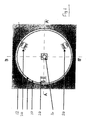
- Fig. 1 is a schematic plan view of a camera forming one embodiment of the invention;
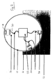
- Fig. 2 is a cross-sectional end view taken on the line A-A' of Fig. 1; and
- Fig. 3 is a cross-sectional side view taken on the line B-B' of Fig. 1.
- The camera comprises a
sphere 10 and abase 12. Thebase 12 has ahemispherical cavity 14 which has a slightly larger diameter than that of thesphere 10. This arrangement allows thesphere 10 to be rotated within thebase 12 by the hand. - An
imaging sensor 16 is mounted adjacent the surface of thesphere 10. As schematically shown in the drawings, the imaging sensor comprises alens 18 and animage capture device 20, which may suitably be a single-chip digital camera. Thelens 18 may be a single-element plastic lens, or may be a more sophisticated lens system such as a single- or multi-element glass lens. Theimage capture device 20 may suitably be a relatively low-resolution 2-D image sensor, such as a CIF 352x288 pixel sensor or a VGA 640x480 pixel sensor. - The
sphere 10 also houses anelectronics package 22 which contains processing circuitry and a battery to power the camera. Thepackage 22 is preferably situated at the centre of thesphere 10 to assist in rotational balancing of thesphere 10. The processing circuitry may conveniently be provided in the form of a general purpose microprocessor, suitably programmed. - The
sphere 10 is provided with four motion sensors 24a-d. Themotion sensors 24 in this example are positioned in the hemisphere opposite to that in which theimaging sensor 16 is located. Specifically, taking theimaging sensor 16 as located at the North pole, themotion sensors 24 are located one at the South pole and the other three at 30º South and at longitudes of 0º, 120º East and 120º West. - The
motion sensors 24 are most suitably motion sensors as used in "optical mice" which are manufactured in large quantities and are thus readily available at low cost. As is well known, such sensors give output signals representing relative X-Y motion between the sensor and a surface over which it passes. The positioning of thesensors 24 described above is chosen such that, for motion of theimaging sensor 16 through an entire hemisphere, there will always be a minimum of two motion sensors within thecavity 14. This is to avoid the situation of a single sensor being within the cavity, and thesphere 10 rotated about an axis passing through the sensor. - The
motion sensors 24 provide output signals to theelectronics package 22 by transmission paths 26, which could conveniently be USB, PS2, I2C, SPI, or wireless links. - To image a volume of space, the
base 12 is placed on a surface and thesphere 10 is placed in thecavity 14 with theimaging sensor 16 unobscured by the base. Thesphere 10 is rotated by hand around the vertical and the two horizontal axes until the whole of the scene has been imaged. - As the
sphere 10 is rotated, the output from theimaging sensor 16 is captured by the microprocessor, along with the data from themotion sensors 24. Optical mice sensors have great accuracy (20 counts per mm is typical) and can operate at high speed (in excess of 100 mm per second). This enables thesphere 10 to be rotated at relatively high speed, e.g. a 100 mm sphere could be rotated through 360º in approximately 3 seconds. - As the
sphere 10 is rotated, themotion sensors 24 observe the surface of thecavity 14 and calculate the direction of motion. Optical mouse sensors are designed to operate on a flat surface and output X/Y coordinates of motion across this surface. In this application, as the motion is spherical it is convenient to use spherical polar coordinates using angles of rotation around three mutually orthogonal axes. As a single mouse sensor outputs only two sets of information, a minimum of two sensors must image thecavity 14 at any given time. Optimally these are disposed at 90º with respect to the centre of the sphere; if they were at 180º they would form an axis, and in the event of rotation about this axis there would be no output from the sensors. The preferred locations for the sensors is as detailed above. - As the
sphere 10 is rotated, there will be positions in which one or more of themotion sensors 24 will not be observing thebase 12 and their motion must be disregarded. Fortunately, optical mice sensors incorporate techniques to inhibit the output if they are not observing a useful surface. This can be used in the present embodiment to ignore from the stitching algorithm any mouse sensor not producing an output. - As the
sphere 10 is rotated, theimaging sensor 16 acquires a series of image frames. The directional information from themotion sensors 24 allows the relative alignments of the frames to be calculated, and the images can be stitched together using readily available software. - The processing system may operate in real time to stitch the images together. In this case, the system can provide feedback to an operator (e.g. in the form of an audible bleep or a visual signal LED) that the whole scene has been successfully captured.
- A lower cost system could merely store the image information along with the motion sensors' output for later processing.
- A medium cost system would not process and stitch the images in real time, but analyse the data from the motion sensors and provide feedback to the user once the whole scene has been captured.
- Modifications may be made to the foregoing embodiment within the scope of the invention.
- The camera sphere could be moved by motors rather than by hand. This may be done for example by motors mounted in the base and driving the sphere through contact wheels.
- The motion sensors, instead of being mounted on the sphere, could be mounted on the base, facing the sphere. In this case it would suffice to use three motion sensors, or even two motion sensors provided they are not aligned with each other.
- As noted above, the "optical mouse" type of motion sensor is preferred for simplicity and low cost. However, in principle any suitable form of motion sensor may be used, for example contact-wheel type mouse sensors.
- The camera can be arranged to image more than a hemisphere. For example, if it is desired to image below the horizontal equatorial plane, the base may be reduced to less than a hemisphere. There has to be sufficient part-sphere to sphere contact to retain the sphere in place and allow easy manipulation, and additional motion sensors may be required.
- The invention is also applicable to cameras imaging smaller, but still panoramic, views. For example, it may be desired to image a restricted vertical angle over an azimuth of 360º or less, say in the form of a panoramic group photograph. This requirement could be met by a combination of camera housing and base other than spherical/part-spherical, such as a cylindrical camera housing having its lower end rotating within a cylindrical base cavity.
- The processing electronics may be located outside the camera sphere and receive image and motion sensor signals by wireless transfer. This could conveniently be done by a commercially available system such as Bluetooth or WiFi. In this case, the processing could be carried out on a suitably programmed PC or PDA.
- The invention thus enables the provision of a panoramic camera which is simple, easily portable and economic to manufacture. The use of readily available components such as mouse sensors and lower resolution image sensors, and the fact that the physical components such as the sphere and base can be easily made by techniques such as injection moulding of plastics, leads to low costs. Its simple mechanical construction means that it is easily installed, which is important for such applications as real estate viewing, and light weight for greater portability.
Claims (12)
- A panoramic camera comprising:a camera housing having an exterior shape which comprises a surface which is rotationally symmetrical around at least one axis;a base having a cavity in which the camera housing is receivable, the cavity having a shape cooperating with that of the camera housing such that the camera housing may be rotated within the cavity about said at least one axis;an image capture device mounted in the camera housing and viewing the exterior along an optical axis;motion sensor means mounted on one of the camera housing and the base for detecting relative rotary motion between the camera housing and the base; andsignal transmission means for communicating image data and motion sensor data to a processing means.
- The camera of claim 1, in which the camera housing is spherical and the cavity is part-spherical.
- The camera of claim 1 or claim 2, in which the motion sensor means comprises a plurality of mouse sensors.
- The camera of claim 3, in which the mouse sensors are mounted in the camera housing.
- The camera of claim 4, in which the base cavity is a half sphere and there are four mouse sensors.
- The camera of any of claims 3 to 5, in which the mouse sensors are optical mouse sensors.
- The camera of any preceding claim, including image processing circuitry located within the camera housing, the signal transmission means being internal to the camera housing.
- The camera of any of claims 1 to 6, in which the signal transmission means comprises wireless signal transmission means for transmitting camera and motion detection signals to a remote processor.
- The camera of claim 8 in combination with a general purpose computer in wireless communication with the signal transmission means, the computer being programmed to stitch together received images.
- The camera of any preceding claim, including indicator means for indicating to a user when the whole of a desired scene has been imaged.
- The camera of any preceding claim, in which the camera housing is manually movable within the base.
- The camera of any of claims 1 to 11, including motor means for moving the camera housing within the base.
Priority Applications (2)
| Application Number | Priority Date | Filing Date | Title |
|---|---|---|---|
| EP06252702A EP1860867A1 (en) | 2006-05-24 | 2006-05-24 | Panoramic camera |
| US11/752,506 US8456513B2 (en) | 2006-05-24 | 2007-05-23 | Panoramic camera |
Applications Claiming Priority (1)
| Application Number | Priority Date | Filing Date | Title |
|---|---|---|---|
| EP06252702A EP1860867A1 (en) | 2006-05-24 | 2006-05-24 | Panoramic camera |
Publications (1)
| Publication Number | Publication Date |
|---|---|
| EP1860867A1 true EP1860867A1 (en) | 2007-11-28 |
Family
ID=37396924
Family Applications (1)
| Application Number | Title | Priority Date | Filing Date |
|---|---|---|---|
| EP06252702A Withdrawn EP1860867A1 (en) | 2006-05-24 | 2006-05-24 | Panoramic camera |
Country Status (2)
| Country | Link |
|---|---|
| US (1) | US8456513B2 (en) |
| EP (1) | EP1860867A1 (en) |
Cited By (3)
| Publication number | Priority date | Publication date | Assignee | Title |
|---|---|---|---|---|
| US7616883B2 (en) * | 2006-04-28 | 2009-11-10 | Eastman Kodak Company | User-rotatable camera for enhancing panoramic image capture |
| DE102011117923A1 (en) * | 2011-11-09 | 2013-05-16 | Diehl Bgt Defence Gmbh & Co. Kg | Seeker head for a guided missile |
| GB2509102A (en) * | 2012-12-20 | 2014-06-25 | Thales Holdings Uk Plc | Using motion sensor data to process images from image sensors with overlapping fields of view |
Families Citing this family (13)
| Publication number | Priority date | Publication date | Assignee | Title |
|---|---|---|---|---|
| TW200907557A (en) * | 2007-08-08 | 2009-02-16 | Behavior Tech Computer Corp | Camera array apparatus and the method for capturing wide-angle video over a network |
| CN101420473A (en) * | 2007-10-22 | 2009-04-29 | 鸿富锦精密工业(深圳)有限公司 | Portable electronic device |
| USD611081S1 (en) * | 2009-05-11 | 2010-03-02 | Chino Corporation | Infrared camera |
| US8469613B2 (en) * | 2011-04-18 | 2013-06-25 | Koozoo Inc. | Anti-glare camera hood with integrated movable lens |
| US9007428B2 (en) | 2011-06-01 | 2015-04-14 | Apple Inc. | Motion-based image stitching |
| US8896713B2 (en) | 2011-08-15 | 2014-11-25 | Apple Inc. | Motion-based video stabilization |
| US8786716B2 (en) | 2011-08-15 | 2014-07-22 | Apple Inc. | Rolling shutter reduction based on motion sensors |
| US9516223B2 (en) | 2012-06-06 | 2016-12-06 | Apple Inc. | Motion-based image stitching |
| US9542585B2 (en) | 2013-06-06 | 2017-01-10 | Apple Inc. | Efficient machine-readable object detection and tracking |
| US11361640B2 (en) | 2017-06-30 | 2022-06-14 | Johnson Controls Tyco IP Holdings LLP | Security camera system with multi-directional mount and method of operation |
| US11288937B2 (en) | 2017-06-30 | 2022-03-29 | Johnson Controls Tyco IP Holdings LLP | Security camera system with multi-directional mount and method of operation |
| US12217447B2 (en) * | 2017-09-29 | 2025-02-04 | Tyco Fire & Security Gmbh | Security camera system with multi-directional mount and method of operation |
| US12620148B2 (en) * | 2023-08-02 | 2026-05-05 | Qualcomm Incorporated | Rollout photography systems and methods for mobile devices |
Citations (5)
| Publication number | Priority date | Publication date | Assignee | Title |
|---|---|---|---|---|
| US5903782A (en) * | 1995-11-15 | 1999-05-11 | Oxaal; Ford | Method and apparatus for producing a three-hundred and sixty degree spherical visual data set |
| WO1999051027A1 (en) * | 1998-03-31 | 1999-10-07 | Intel Corporation | Method of and apparatus for creating panoramic or surround images using a motion sensor equipped camera |
| US6639625B1 (en) * | 1997-07-16 | 2003-10-28 | Minolta Co., Ltd. | Image sensing device |
| WO2004004320A1 (en) * | 2002-07-01 | 2004-01-08 | The Regents Of The University Of California | Digital processing of video images |
| US20060055912A1 (en) * | 2004-09-10 | 2006-03-16 | Honeywell International Inc. | Precise, no-contact, position sensing using imaging |
Family Cites Families (4)
| Publication number | Priority date | Publication date | Assignee | Title |
|---|---|---|---|---|
| IL146802A0 (en) * | 2001-11-28 | 2003-01-12 | Wave Group Ltd | A self-contained panoramic or spherical imaging device |
| IL150746A0 (en) * | 2002-07-15 | 2003-02-12 | Odf Optronics Ltd | Optical lens providing omni-directional coverage and illumination |
| US8063881B2 (en) * | 2005-12-05 | 2011-11-22 | Cypress Semiconductor Corporation | Method and apparatus for sensing motion of a user interface mechanism using optical navigation technology |
| US7627235B2 (en) * | 2006-03-17 | 2009-12-01 | Immersive Media Company | Spinning camera enclosure for environmental protection |
-
2006
- 2006-05-24 EP EP06252702A patent/EP1860867A1/en not_active Withdrawn
-
2007
- 2007-05-23 US US11/752,506 patent/US8456513B2/en not_active Expired - Fee Related
Patent Citations (5)
| Publication number | Priority date | Publication date | Assignee | Title |
|---|---|---|---|---|
| US5903782A (en) * | 1995-11-15 | 1999-05-11 | Oxaal; Ford | Method and apparatus for producing a three-hundred and sixty degree spherical visual data set |
| US6639625B1 (en) * | 1997-07-16 | 2003-10-28 | Minolta Co., Ltd. | Image sensing device |
| WO1999051027A1 (en) * | 1998-03-31 | 1999-10-07 | Intel Corporation | Method of and apparatus for creating panoramic or surround images using a motion sensor equipped camera |
| WO2004004320A1 (en) * | 2002-07-01 | 2004-01-08 | The Regents Of The University Of California | Digital processing of video images |
| US20060055912A1 (en) * | 2004-09-10 | 2006-03-16 | Honeywell International Inc. | Precise, no-contact, position sensing using imaging |
Cited By (4)
| Publication number | Priority date | Publication date | Assignee | Title |
|---|---|---|---|---|
| US7616883B2 (en) * | 2006-04-28 | 2009-11-10 | Eastman Kodak Company | User-rotatable camera for enhancing panoramic image capture |
| DE102011117923A1 (en) * | 2011-11-09 | 2013-05-16 | Diehl Bgt Defence Gmbh & Co. Kg | Seeker head for a guided missile |
| GB2509102A (en) * | 2012-12-20 | 2014-06-25 | Thales Holdings Uk Plc | Using motion sensor data to process images from image sensors with overlapping fields of view |
| GB2509102B (en) * | 2012-12-20 | 2015-09-02 | Thales Holdings Uk Plc | Image processor for processing images received from a plurality of image sensors |
Also Published As
| Publication number | Publication date |
|---|---|
| US8456513B2 (en) | 2013-06-04 |
| US20070285562A1 (en) | 2007-12-13 |
Similar Documents
| Publication | Publication Date | Title |
|---|---|---|
| US8456513B2 (en) | Panoramic camera | |
| US11560920B2 (en) | Gimbal for image capturing | |
| US7912320B1 (en) | Method and apparatus for photographic measurement | |
| Yagi | Omnidirectional sensing and its applications | |
| CN103402052B (en) | Rotationally symmetrical pantoscope is utilized to obtain panorama and the method and apparatus of rectilinear images | |
| US7176960B1 (en) | System and methods for generating spherical mosaic images | |
| CN113532329B (en) | Calibration method with projected light spot as calibration point | |
| US10674121B2 (en) | Lens system for use in image capture device | |
| US20160381257A1 (en) | Sphere panorama image capturing device | |
| US20090244700A1 (en) | Telescope system and method of use | |
| JP2011027718A (en) | Derivation of 3-dimensional information from single camera and movement sensor | |
| US9106901B2 (en) | Imagery axle turning method for stereo vision and apparatus thereof | |
| KR20170095716A (en) | 360 degree image capture apparatus enclosed in a ball-shape housing | |
| EP2685707A1 (en) | System for spherical video shooting | |
| CN111429523A (en) | A long-distance calibration method in 3D modeling | |
| US20130250126A1 (en) | Tracking apparatus | |
| CN111445528A (en) | Multi-camera common calibration method in 3D modeling | |
| US7604589B2 (en) | Device, system and method for determining orientation of in-vivo devices | |
| KR20220010235A (en) | Rotating imaging apparatus for ship | |
| CN108124127A (en) | Panoramic scanning monitoring system | |
| CN114255284A (en) | Camera calibration system and method | |
| JPH10185563A (en) | Photogrammetry target and photogrammetry using this photogrammetry target | |
| CN206775653U (en) | More depth camera compact panoramic scanning equipment | |
| KR20070074996A (en) | 3D driving binocular camera device | |
| JP4918675B2 (en) | 3D coordinate measurement method |
Legal Events
| Date | Code | Title | Description |
|---|---|---|---|
| PUAI | Public reference made under article 153(3) epc to a published international application that has entered the european phase |
Free format text: ORIGINAL CODE: 0009012 |
|
| AK | Designated contracting states |
Kind code of ref document: A1 Designated state(s): AT BE BG CH CY CZ DE DK EE ES FI FR GB GR HU IE IS IT LI LT LU LV MC NL PL PT RO SE SI SK TR |
|
| AX | Request for extension of the european patent |
Extension state: AL BA HR MK YU |
|
| 17P | Request for examination filed |
Effective date: 20080513 |
|
| AKX | Designation fees paid |
Designated state(s): DE FR GB IT |
|
| 17Q | First examination report despatched |
Effective date: 20080714 |
|
| STAA | Information on the status of an ep patent application or granted ep patent |
Free format text: STATUS: THE APPLICATION HAS BEEN WITHDRAWN |
|
| 18W | Application withdrawn |
Effective date: 20141017 |