EP1860849A1 - Camera protection cover - Google Patents
Camera protection cover Download PDFInfo
- Publication number
- EP1860849A1 EP1860849A1 EP07252126A EP07252126A EP1860849A1 EP 1860849 A1 EP1860849 A1 EP 1860849A1 EP 07252126 A EP07252126 A EP 07252126A EP 07252126 A EP07252126 A EP 07252126A EP 1860849 A1 EP1860849 A1 EP 1860849A1
- Authority
- EP
- European Patent Office
- Prior art keywords
- slidable cover
- hand
- portable electronic
- body part
- electronic apparatus
- Prior art date
- Legal status (The legal status is an assumption and is not a legal conclusion. Google has not performed a legal analysis and makes no representation as to the accuracy of the status listed.)
- Granted
Links
- 238000003384 imaging method Methods 0.000 claims abstract description 40
- 238000000034 method Methods 0.000 claims description 8
- 230000009471 action Effects 0.000 description 5
- 230000000712 assembly Effects 0.000 description 5
- 238000000429 assembly Methods 0.000 description 5
- 230000007246 mechanism Effects 0.000 description 5
- 230000000694 effects Effects 0.000 description 2
- 238000004519 manufacturing process Methods 0.000 description 2
- 238000003825 pressing Methods 0.000 description 2
- 230000008901 benefit Effects 0.000 description 1
- 230000001413 cellular effect Effects 0.000 description 1
- 230000000593 degrading effect Effects 0.000 description 1
- 238000002955 isolation Methods 0.000 description 1
- 238000012986 modification Methods 0.000 description 1
- 230000004048 modification Effects 0.000 description 1
- 230000002265 prevention Effects 0.000 description 1
- 230000008569 process Effects 0.000 description 1
- 230000001681 protective effect Effects 0.000 description 1
- 238000006467 substitution reaction Methods 0.000 description 1
Images


Classifications
-
- H—ELECTRICITY
- H04—ELECTRIC COMMUNICATION TECHNIQUE
- H04N—PICTORIAL COMMUNICATION, e.g. TELEVISION
- H04N23/00—Cameras or camera modules comprising electronic image sensors; Control thereof
- H04N23/57—Mechanical or electrical details of cameras or camera modules specially adapted for being embedded in other devices
-
- H—ELECTRICITY
- H04—ELECTRIC COMMUNICATION TECHNIQUE
- H04M—TELEPHONIC COMMUNICATION
- H04M1/00—Substation equipment, e.g. for use by subscribers
- H04M1/02—Constructional features of telephone sets
- H04M1/0202—Portable telephone sets, e.g. cordless phones, mobile phones or bar type handsets
- H04M1/0206—Portable telephones comprising a plurality of mechanically joined movable body parts, e.g. hinged housings
- H04M1/0208—Portable telephones comprising a plurality of mechanically joined movable body parts, e.g. hinged housings characterized by the relative motions of the body parts
-
- H—ELECTRICITY
- H04—ELECTRIC COMMUNICATION TECHNIQUE
- H04M—TELEPHONIC COMMUNICATION
- H04M1/00—Substation equipment, e.g. for use by subscribers
- H04M1/02—Constructional features of telephone sets
- H04M1/0202—Portable telephone sets, e.g. cordless phones, mobile phones or bar type handsets
- H04M1/026—Details of the structure or mounting of specific components
- H04M1/0266—Details of the structure or mounting of specific components for a display module assembly
-
- H—ELECTRICITY
- H04—ELECTRIC COMMUNICATION TECHNIQUE
- H04N—PICTORIAL COMMUNICATION, e.g. TELEVISION
- H04N23/00—Cameras or camera modules comprising electronic image sensors; Control thereof
- H04N23/50—Constructional details
-
- H—ELECTRICITY
- H04—ELECTRIC COMMUNICATION TECHNIQUE
- H04N—PICTORIAL COMMUNICATION, e.g. TELEVISION
- H04N23/00—Cameras or camera modules comprising electronic image sensors; Control thereof
- H04N23/50—Constructional details
- H04N23/51—Housings
-
- H—ELECTRICITY
- H04—ELECTRIC COMMUNICATION TECHNIQUE
- H04N—PICTORIAL COMMUNICATION, e.g. TELEVISION
- H04N23/00—Cameras or camera modules comprising electronic image sensors; Control thereof
- H04N23/50—Constructional details
- H04N23/53—Constructional details of electronic viewfinders, e.g. rotatable or detachable
-
- H—ELECTRICITY
- H04—ELECTRIC COMMUNICATION TECHNIQUE
- H04M—TELEPHONIC COMMUNICATION
- H04M1/00—Substation equipment, e.g. for use by subscribers
- H04M1/02—Constructional features of telephone sets
- H04M1/0202—Portable telephone sets, e.g. cordless phones, mobile phones or bar type handsets
- H04M1/026—Details of the structure or mounting of specific components
- H04M1/0264—Details of the structure or mounting of specific components for a camera module assembly
-
- H—ELECTRICITY
- H04—ELECTRIC COMMUNICATION TECHNIQUE
- H04M—TELEPHONIC COMMUNICATION
- H04M2250/00—Details of telephonic subscriber devices
- H04M2250/20—Details of telephonic subscriber devices including a rotatable camera
-
- H—ELECTRICITY
- H04—ELECTRIC COMMUNICATION TECHNIQUE
- H04N—PICTORIAL COMMUNICATION, e.g. TELEVISION
- H04N7/00—Television systems
- H04N7/14—Systems for two-way working
- H04N7/141—Systems for two-way working between two video terminals, e.g. videophone
- H04N7/142—Constructional details of the terminal equipment, e.g. arrangements of the camera and the display
- H04N2007/145—Handheld terminals
Definitions
- the invention relates to camera-containing hand-portable electronic devices, and in particular to such devices incorporating features to protect the camera in the device, including associated apparatus and methods (e.g. methods of assembly and/or operation of the apparatus/device).
- Such hand-portable electronic devices may encompass, for example, user-portable radio telephones (commonly known as mobile or cellular telephones), personal digital assistants (PDAs), portable video gaming devices, portable digital audio/video playback/recording devices or other devices incorporating one or more of the features of the aforementioned.
- PDAs personal digital assistants
- portable video gaming devices portable digital audio/video playback/recording devices or other devices incorporating one or more of the features of the aforementioned.
- Such hand-portable electronic devices tend to incorporate digital camera assemblies of increasing quality and functionality as various manufacturers compete with each other to provide improved facilities while maintaining portability of the device.
- An adjustable camera assembly may typically be within a rotatable body part of the hand-portable electronic device. An imaging axis of the camera assembly may thereby be rotated towards or away from the user as desired.
- imaging axis used herein is intended primarily to be defined as being an imaginary axis drawn through an axis of rotational symmetry of a lens within the camera assembly. An imaging axis of a camera assembly will thereby typically be in line with the approximate centre of the field of view of the camera assembly.
- the imaging axis may alternatively be defined as being an imaginary line drawn from the centre of the imaging window of the camera assembly to the centre of the field of view being imaged by the camera assembly.
- a hand-portable electronic device having first and second body parts being rotatable relative to each other by means of a swivel hinge.
- the second body part comprises a digital camera input device
- the first body part comprises a screen for viewing images captured by the camera. Rotation of the second body part relative to the first body part allows the camera to be oriented in various directions relative to the screen.
- a possible problem with such prior art hand-portable electronic devices incorporating a rotatable camera assembly is that inadvertent rotation of the camera assembly may occur when being carried, for example in a pocket or a handbag. Also, the imaging window or lens of the camera assembly may, when subjected to rough handling in transit, be scratched or soiled, thus degrading the quality of the images captured by the camera assembly.
- Slidable lens covers are known and possible in hand-portable electronic devices. Locking mechanisms for the prevention of inadvertent rotation of rotatable camera assemblies are also known. However, there is a general need to simplify the use and manufacture of such devices, using as few mechanical components as possible, so as to reduce the overall manufacturing cost. Combining more than one feature in a mechanical component of a hand-portable electronic device would go some way to fulfilling this need.
- Some embodiments provide a hand-portable electronic device comprising a rotatable camera assembly with a mechanism for both protecting the imaging window or lens of the camera assembly and for locking the rotating mechanism of the device, thus protecting the hand-portable electronic device from the effects of handling and transit in normal use.
- Some embodiments provide a rotatable camera assembly in a hand-portable electronic device that can be provided with a protective cover and a rotation locking mechanism with a reduced number of mechanical parts.
- a hand-portable electronic apparatus comprising:
- a hand-portable electronic device is illustrated in figure 1.
- the hand-portable electronic device 10 shown in a closed configuration, comprises a first body part 11 and a second body part 12.
- the first body part 11 may comprise a screen 18 and a first user input area 19a.
- the second body part 12 may comprise a second user input area 19b and a camera assembly 14.
- the camera assembly 14 further comprises a lens or imaging window 16.
- the screen 18 of the hand-portable electronic device may be used to view images captured from the camera assembly 14.
- the user input areas 19a, 19b may comprise touch sensitive areas such as alphanumeric input keys and/or a touch sensitive writing area.
- the screen 18 may also serve as a touch sensitive user input area.
- the hand-portable electronic device may also comprise one or more other input or output features or areas.
- the first body part 11 and second body part 12 are rotatably connected to each other via an internal rotatable hinge (not shown), which enables the parts 11, 12 to rotate relative to each other about a rotation axis 17.
- the camera assembly 14 comprised within the second body part 12 may optionally be configured such that an imaging axis 15 is oriented orthogonally to the rotation axis 17. Whichever way the imaging axis 15 is directed as the second body part 12 rotates relative to the first body part 11, the imaging axis 15 then remains orthogonal to the rotation axis 17.
- a slidable cover 13 is shown comprised in the first body part 11, the slidable cover 13 being in a first position in which the first and second body parts 11, 12 are able to rotate relative to each other.
- This slidable cover 13 is shown in figure 2 in a second position in which the slidable cover 13 has been moved from its first position to cover the imaging window or lens 16 of the camera assembly 14, thus crossing the imaging axis 15 in the process.
- the slidable cover 13 serves both to cover the imaging window 16 and to lock the first and second body parts 11, 12 to each other.
- the first and second body parts 1 l, 12 are thereby prevented from rotating relative to each other.
- This arrangement has the advantage of protecting the camera assembly 14 from damage or soiling during handling when the hand-portable electronic device is in the closed configuration of figures 1 and 2.
- the slidable cover 13 is typically incorporated in the first body part 11. Sliding the slidable cover 13 from the aforementioned first position in which the slidable cover 13 is disengaged from the second body part 12 to the second position engages the first and second body parts 11, 12 and thereby prevents relative rotation of the first and second body parts 11, 12.
- the slidable cover 13 may be incorporated in the second body part 12 when the device is in the open configuration.
- the slidable cover 13 may be adapted to retract from engagement with the first body part 11 into the second body part 12 to allow for relative rotation of the first and second body parts. The slidable cover 13 in the retracted position would therefore be located on the opposite side of the imaging window 16.
- Figure 2 shows the hand-portable electronic device 10 of figure 1 with the slidable cover 13 in the second position, having been moved from the first position of figure 1 in the direction indicated by arrow 21.
- the slidable cover 13 is shown covering the imaging window 16 of the camera assembly 14. Due to the slidable cover 13 still being engaged with the first body portion, the first and second body parts 11, 12 are thereby locked together as regards relative rotation about the rotation axis 17. Engagement between the slidable cover 13 and the first and second body parts 11, 12 may be achieved by means of a releasable catch or detent for maintaining the slidable cover 13 in the second position. A further releasable catch or detent may be provided to maintain the slidable cover 13 in the first position.
- Such releasable catches or detents may be releasable by various user actions such as a sliding action or a combination of pressing and sliding actions. For example, releasing the slidable cover 13 from the first position and moving it towards the second position may be achieved by first a pressing action followed by a sliding action on the slidable cover 13.
- the slidable cover may be provided with a resilient means to effect a spring-loading mechanism that returns the slidable cover to the first position when released from the second position.
- the slidable cover 13 may further be spring loaded to maintain the slidable cover 13 in the first position.
- the second body part 12 With the slidable cover 13 in the first position, the second body part 12 may be rotated about the rotation axis 17 from the closed configuration of figure 1 to an open configuration, as for example that shown in figure 3.
- the direction of rotation is indicated by arrow 31.
- the second body part 12 is rotated relative to the first body part 11, thus rotating the imaging axis 15 but maintaining the imaging axis 15 orthogonal to the rotation axis 17.
- the second body part 12 may alternatively be rotated in the opposite direction, as indicated by arrow 41 in figure 4.
- figure 3 illustrates a configuration in which the user may both view the screen 18 and capture a self-portrait image from the camera assembly 14
- figure 4 shows an arrangement where the user can view on the screen 18 an image taken by the camera assembly 14 in front of the user.
- a further embodiment of the hand-portable electronic device 10 of the invention is shown in figure 5.
- the hand-portable electronic device 10 is in a closed configuration, with the slidable cover 13 in the aforementioned second position.
- One or more interfaces 50 may be provided in the first body part 11.
- One of these interfaces 50 may, for example, comprise a socket 51 for data transfer between the hand-portable electronic device and an external device.
- the socket 51 may, for example, be a (e.g. mini) USB (Universal Serial Bus) socket.
- USB Universal Serial Bus
- Figure 6 illustrates an exemplary embodiment of a hand-portable electronic device 10 of the invention.
- the slidable cover 13 comprised within the first body part 11 is adapted to be moved from the position shown to one in which the slidable cover 13 covers the imaging window 16 of the camera assembly 14 comprised within the second body part 12.
- the hand-portable electronic device of the embodiment shown further comprises a flash module 61 adjacent the camera assembly 14.
- the flash module may in this case also be covered and thereby protected by moving the slidable cover 13 from the first position to the second position.
- Figure 7 shows the hand-portable electronic device 10 of figure 6 when in an open configuration, with the imaging window 16 facing away from the screen (18, figures 1-5).
- the second body part 12 is rotated approximately 90 degrees relative to the first body part 11.
Landscapes
- Engineering & Computer Science (AREA)
- Signal Processing (AREA)
- Multimedia (AREA)
- Studio Devices (AREA)
- Telephone Set Structure (AREA)
- Casings For Electric Apparatus (AREA)
- Rear-View Mirror Devices That Are Mounted On The Exterior Of The Vehicle (AREA)
- Measurement Of Radiation (AREA)
Abstract
Description
- The invention relates to camera-containing hand-portable electronic devices, and in particular to such devices incorporating features to protect the camera in the device, including associated apparatus and methods (e.g. methods of assembly and/or operation of the apparatus/device).
- It is now common to find digital camera assemblies incorporated into many types of hand-portable electronic devices other than digital cameras. Such hand-portable electronic devices may encompass, for example, user-portable radio telephones (commonly known as mobile or cellular telephones), personal digital assistants (PDAs), portable video gaming devices, portable digital audio/video playback/recording devices or other devices incorporating one or more of the features of the aforementioned. Such hand-portable electronic devices tend to incorporate digital camera assemblies of increasing quality and functionality as various manufacturers compete with each other to provide improved facilities while maintaining portability of the device.
- With increasing quality of camera assemblies comes an increased need for protection of the imaging window of the digital camera assembly. Typically, as the quality of the camera assembly increases, for example increasing with the number of pixels an imaging chip in the assembly is able to image, the requirement for larger and higher quality lenses increases. Larger lenses let more light into the camera assembly, and can thereby improve the image quality. To maintain the quality of the images, however, some kind of lens cover is preferred, in order to protect the camera assembly from scratches and other marks which can be an inevitable result of the typical use pattern of a hand portable electronic device such as a mobile telephone.
- Additionally, when camera assemblies are incorporated into hand-portable electronic devices, there is now a preference for the camera assembly to be adjustable such that images can be taken of either the user or of a scene in front of the user while the user views the image via a screen on the device. An adjustable camera assembly may typically be within a rotatable body part of the hand-portable electronic device. An imaging axis of the camera assembly may thereby be rotated towards or away from the user as desired.
- It is to be understood that the term "imaging axis" used herein is intended primarily to be defined as being an imaginary axis drawn through an axis of rotational symmetry of a lens within the camera assembly. An imaging axis of a camera assembly will thereby typically be in line with the approximate centre of the field of view of the camera assembly. The imaging axis may alternatively be defined as being an imaginary line drawn from the centre of the imaging window of the camera assembly to the centre of the field of view being imaged by the camera assembly.
- One particular type of rotatable camera assembly found in a mobile telephone is described in
WO 2005/083990 , in which a hand-portable electronic device is disclosed having first and second body parts being rotatable relative to each other by means of a swivel hinge. The second body part comprises a digital camera input device, while the first body part comprises a screen for viewing images captured by the camera. Rotation of the second body part relative to the first body part allows the camera to be oriented in various directions relative to the screen. - A possible problem with such prior art hand-portable electronic devices incorporating a rotatable camera assembly is that inadvertent rotation of the camera assembly may occur when being carried, for example in a pocket or a handbag. Also, the imaging window or lens of the camera assembly may, when subjected to rough handling in transit, be scratched or soiled, thus degrading the quality of the images captured by the camera assembly.
- Slidable lens covers are known and possible in hand-portable electronic devices. Locking mechanisms for the prevention of inadvertent rotation of rotatable camera assemblies are also known. However, there is a general need to simplify the use and manufacture of such devices, using as few mechanical components as possible, so as to reduce the overall manufacturing cost. Combining more than one feature in a mechanical component of a hand-portable electronic device would go some way to fulfilling this need.
- Some embodiments provide a hand-portable electronic device comprising a rotatable camera assembly with a mechanism for both protecting the imaging window or lens of the camera assembly and for locking the rotating mechanism of the device, thus protecting the hand-portable electronic device from the effects of handling and transit in normal use.
- Some embodiments provide a rotatable camera assembly in a hand-portable electronic device that can be provided with a protective cover and a rotation locking mechanism with a reduced number of mechanical parts.
- According to a first aspect, there is provided a hand-portable electronic apparatus comprising:
- a first body part;
- a second body part rotatably connected to the first body part, the second body part comprising a camera assembly having an imaging axis and an imaging window; and
- a slidable cover,
- the first and second body parts being rotatable with respect to each other about a rotation axis,
- the apparatus arranged such that the slidable cover is able to slide between:
- i) a first position, in which the first and second body parts are unlocked and are thereby able to rotate about the rotation axis relative to one another; and
- ii) a second position, in which the first and second body parts are locked by engagement of the slidable cover therebetween, relative rotation of the first and second body parts being thereby prevented, and in which the slidable cover substantially covers the imaging window
- Corresponding means for performing one or more of the functions described herein are within the present disclosure.
- Embodiments of the present invention will now be described by way of example and with reference to the accompanying drawings in which:
- figure 1 illustrates a schematic isometric view of a hand-portable electronic device in a closed configuration;
- figure 2 illustrates a schematic isometric view of the hand-portable electronic device of figure 1 in which a slidable cover is shown covering an imaging window of a camera assembly;
- figure 3 illustrates a schematic isometric view of the hand-portable electronic device of figure 1 in a first open configuration;
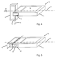
- figure 4 illustrates a schematic isometric view of the hand-portable electronic device of figure 1 in a second open configuration;
- figure 5 illustrates a schematic isometric view of a hand-portable electronic device comprising interfaces for data transfer between the hand-portable electronic device and an external device;
- figure 6 illustrates a perspective view of a hand-portable electronic device according to an embodiment of the invention; and
- figure 7 illustrates a perspective view of the hand portable electronic device of figure 6 when in an open configuration.
- A hand-portable electronic device according to an embodiment of the invention is illustrated in figure 1. The hand-portable
electronic device 10, shown in a closed configuration, comprises afirst body part 11 and asecond body part 12. Thefirst body part 11 may comprise ascreen 18 and a firstuser input area 19a. Thesecond body part 12 may comprise a seconduser input area 19b and acamera assembly 14. Thecamera assembly 14 further comprises a lens orimaging window 16. - The
screen 18 of the hand-portable electronic device may be used to view images captured from thecamera assembly 14. Theuser input areas screen 18 may also serve as a touch sensitive user input area. The hand-portable electronic device may also comprise one or more other input or output features or areas. - The
first body part 11 andsecond body part 12 are rotatably connected to each other via an internal rotatable hinge (not shown), which enables theparts rotation axis 17. Thecamera assembly 14 comprised within thesecond body part 12 may optionally be configured such that animaging axis 15 is oriented orthogonally to therotation axis 17. Whichever way theimaging axis 15 is directed as thesecond body part 12 rotates relative to thefirst body part 11, theimaging axis 15 then remains orthogonal to therotation axis 17. - In figure 1 a
slidable cover 13 is shown comprised in thefirst body part 11, theslidable cover 13 being in a first position in which the first andsecond body parts slidable cover 13 is shown in figure 2 in a second position in which theslidable cover 13 has been moved from its first position to cover the imaging window orlens 16 of thecamera assembly 14, thus crossing theimaging axis 15 in the process. In the second position, theslidable cover 13 serves both to cover theimaging window 16 and to lock the first andsecond body parts second body parts 1 l, 12 are thereby prevented from rotating relative to each other. This arrangement has the advantage of protecting thecamera assembly 14 from damage or soiling during handling when the hand-portable electronic device is in the closed configuration of figures 1 and 2. - The
slidable cover 13 is typically incorporated in thefirst body part 11. Sliding theslidable cover 13 from the aforementioned first position in which theslidable cover 13 is disengaged from thesecond body part 12 to the second position engages the first andsecond body parts second body parts - Alternatively, in certain embodiments the
slidable cover 13 may be incorporated in thesecond body part 12 when the device is in the open configuration. In these alternative embodiments, theslidable cover 13 may be adapted to retract from engagement with thefirst body part 11 into thesecond body part 12 to allow for relative rotation of the first and second body parts. Theslidable cover 13 in the retracted position would therefore be located on the opposite side of theimaging window 16. - Figure 2 shows the hand-portable
electronic device 10 of figure 1 with theslidable cover 13 in the second position, having been moved from the first position of figure 1 in the direction indicated byarrow 21. Theslidable cover 13 is shown covering theimaging window 16 of thecamera assembly 14. Due to theslidable cover 13 still being engaged with the first body portion, the first andsecond body parts rotation axis 17. Engagement between theslidable cover 13 and the first andsecond body parts slidable cover 13 in the second position. A further releasable catch or detent may be provided to maintain theslidable cover 13 in the first position. Such releasable catches or detents may be releasable by various user actions such as a sliding action or a combination of pressing and sliding actions. For example, releasing the slidable cover 13 from the first position and moving it towards the second position may be achieved by first a pressing action followed by a sliding action on theslidable cover 13. The slidable cover may be provided with a resilient means to effect a spring-loading mechanism that returns the slidable cover to the first position when released from the second position. Theslidable cover 13 may further be spring loaded to maintain theslidable cover 13 in the first position. - With the
slidable cover 13 in the first position, thesecond body part 12 may be rotated about therotation axis 17 from the closed configuration of figure 1 to an open configuration, as for example that shown in figure 3. The direction of rotation is indicated byarrow 31. In figure 3, thesecond body part 12 is rotated relative to thefirst body part 11, thus rotating theimaging axis 15 but maintaining theimaging axis 15 orthogonal to therotation axis 17. - The
second body part 12 may alternatively be rotated in the opposite direction, as indicated byarrow 41 in figure 4. Whereas figure 3 illustrates a configuration in which the user may both view thescreen 18 and capture a self-portrait image from thecamera assembly 14, figure 4 shows an arrangement where the user can view on thescreen 18 an image taken by thecamera assembly 14 in front of the user. - A further embodiment of the hand-portable
electronic device 10 of the invention is shown in figure 5. In this, the hand-portableelectronic device 10 is in a closed configuration, with theslidable cover 13 in the aforementioned second position. One ormore interfaces 50 may be provided in thefirst body part 11. One of theseinterfaces 50 may, for example, comprise asocket 51 for data transfer between the hand-portable electronic device and an external device. Thesocket 51 may, for example, be a (e.g. mini) USB (Universal Serial Bus) socket. With theslidable cover 13 in the second position, the one ormore interfaces 50 are revealed, thus allowing the user to, for example, transfer images taken with thecamera assembly 14 to an external device such as a personal computer. When the camera assembly is in use, theinterfaces 50 are not needed or are disabled, and so are hidden beneath theslidable cover 13 when in the first position. - Figure 6 illustrates an exemplary embodiment of a hand-portable
electronic device 10 of the invention. Theslidable cover 13 comprised within thefirst body part 11 is adapted to be moved from the position shown to one in which theslidable cover 13 covers theimaging window 16 of thecamera assembly 14 comprised within thesecond body part 12. The hand-portable electronic device of the embodiment shown further comprises aflash module 61 adjacent thecamera assembly 14. The flash module may in this case also be covered and thereby protected by moving the slidable cover 13 from the first position to the second position. - Figure 7 shows the hand-portable
electronic device 10 of figure 6 when in an open configuration, with theimaging window 16 facing away from the screen (18, figures 1-5). In this open configuration thesecond body part 12 is rotated approximately 90 degrees relative to thefirst body part 11. - The applicant hereby discloses in isolation each individual feature described herein and any combination of two or more such features, to the extent that such features or combinations are capable of being carried out based on the present specification as a whole in the light of the common general knowledge of a person skilled in the art, irrespective of whether such features or combinations of features solve any problems disclosed herein, and without limitation to the scope of the claims. The applicant indicates that aspects of the present invention may consist of any such individual feature or combination of features. In view of the foregoing description it will be evident to a person skilled in the art that various modifications may be made within the scope of the invention.
- While there have been shown and described and pointed out fundamental novel features of the invention as applied to preferred embodiments thereof, it will be understood that various omissions and substitutions and changes in the form and details of the devices and methods described may be made by those skilled in the art without departing from the spirit of the invention. For example, it is expressly intended that all combinations of those elements and/or method steps which perform substantially the same function in substantially the same way to achieve the same results are within the scope of the invention. Moreover, it should be recognized that structures and/or elements and/or method steps shown and/or described in connection with any disclosed form or embodiment of the invention may be incorporated in any other disclosed or described or suggested form or embodiment as a general matter of design choice. It is the intention, therefore, to be limited only as indicated by the scope of the claims appended hereto. Furthermore, in the claims means-plus-function clauses are intended to cover the structures described herein as performing the recited function and not only structural equivalents, but also equivalent structures. Thus although a nail and a screw may not be structural equivalents in that a nail employs a cylindrical surface to secure wooden parts together, whereas a screw employs a helical surface, in the environment of fastening wooden parts, a nail and a screw may be equivalent structures.
Claims (15)
- A hand-portable electronic apparatus comprising:a first body part;a second body part rotatably connected to the first body part, the second body part comprising a camera assembly having an imaging axis and an imaging window; anda slidable cover,the first and second body parts being rotatable with respect to each other about a rotation axis,the apparatus arranged such that the slidable cover is able to slide between:i) a first position, in which the first and second body parts are unlocked and are thereby able to rotate about the rotation axis relative to one another; andii) a second position, in which the first and second body parts are locked by engagement of the slidable cover therebetween, relative rotation of the first and second body parts being thereby prevented, and in which the slidable cover substantially covers the imaging window.
- The hand-portable electronic apparatus of claim 1 wherein the camera assembly is configured such that the imaging axis is orthogonal to the rotation axis.
- The hand-portable electronic apparatus of claim 1 wherein the slidable cover is adapted to slide in a direction parallel to the rotation axis.
- The hand-portable electronic apparatus of claim 1 wherein the slidable cover is comprised wholly within the first body part when the slidable cover is in the second position.
- The hand-portable electronic apparatus of claim 4 wherein the slidable cover is adapted to engage with the second body part when the electronic apparatus is in a closed configuration.
- The hand-portable electronic apparatus of claim 1 wherein the slidable cover is comprised wholly within the second body partwhen the slidable cover is in the second position.
- The hand-portable electronic apparatus of claim 4 wherein the slidable cover is adapted to cover one or more interfaces comprised within the first body part when in the first position and to reveal the one or more interfaces when in the second position.
- The hand-portable electronic apparatus of claim 5 wherein the one or more interfaces comprise a socket for data transfer between the hand-portable electronic apparatus and an external apparatus.
- The hand-portable electronic apparatus of claim 1, the second body part further comprising a flash module, wherein the slidable cover is adapted to substantially cover the flash module when the slidable cover is in the second position.
- The hand portable electronic apparatus of claim1, wherein the apparatus is a device.
- The hand-portable electronic apparatus of claim 1, wherein the apparatus is a device module.
- A hand-portable electronic apparatus comprising:a first means for housing;a second means for housing rotatably connected to the first means for housing, the second means for housing comprising a means for capturing images having an imaging axis and a means for receiving the image; anda means for slidably covering,the first and second means for housing being rotatable with respect to each other about a rotation axis,the apparatus being arranged such that the means for slidably covering is able to slide between:i) a first position, in which the first and second means for housing are unlocked and are thereby able to rotate about the rotation axis relative to one another; andii) a second position, in which the first and second means for housing are locked by engagement of the means for slidably covering therebetween, relative rotation of the first and second means for housing being thereby prevented, and in which the means for slidably covering substantially covers the means for receiving the image.
- The apparatus of claim 12, wherein the means for capturing images is configured such that the imaging axis is orthogonal to the rotation axis.
- The apparatus of claim 12, wherein the means for slidably covering is adapted to slide in a direction parallel to the rotation axis.
- A method of assembling a hand-portable electronic apparatus, the hand-portable electronic apparatus comprising:a first body part;a second body part rotatably connected to the first body part, the second body part comprising a camera assembly having an imaging axis and an imaging window; anda slidable cover,the first and second body parts being rotatable with respect to each other about a rotation axis,the apparatus arranged such that the slidable cover is able to slide between:i) a first position, in which the first and second body parts are unlocked and are thereby able to rotate about the rotation axis relative to one another; andii) a second position, in which the first and second body parts are locked by engagement of the slidable cover therebetween, relative rotation of the first and second body parts being thereby prevented, and in which the slidable cover substantially covers the imaging window, the method comprising assembling together the first/second body parts and the slideable cover such that the slidable cover is able to slide between:i) a first position, in which the first and second body parts are unlocked and are thereby able to rotate about the rotation axis relative to one another; andii) a second position, in which the first and second body parts are locked by engagement of the slidable cover therebetween, relative rotation of the first and second body parts being thereby prevented, and in which the slidable cover substantially covers the imaging window,
Applications Claiming Priority (1)
| Application Number | Priority Date | Filing Date | Title |
|---|---|---|---|
| US11/442,632 US7536099B2 (en) | 2006-05-25 | 2006-05-25 | Camera protection cover |
Publications (2)
| Publication Number | Publication Date |
|---|---|
| EP1860849A1 true EP1860849A1 (en) | 2007-11-28 |
| EP1860849B1 EP1860849B1 (en) | 2009-02-25 |
Family
ID=38521034
Family Applications (1)
| Application Number | Title | Priority Date | Filing Date |
|---|---|---|---|
| EP07252126A Active EP1860849B1 (en) | 2006-05-25 | 2007-05-23 | Camera protection cover |
Country Status (6)
| Country | Link |
|---|---|
| US (1) | US7536099B2 (en) |
| EP (1) | EP1860849B1 (en) |
| KR (1) | KR100871214B1 (en) |
| CN (1) | CN100569053C (en) |
| AT (1) | ATE424088T1 (en) |
| DE (1) | DE602007000576D1 (en) |
Cited By (1)
| Publication number | Priority date | Publication date | Assignee | Title |
|---|---|---|---|---|
| CN101621552A (en) * | 2008-07-04 | 2010-01-06 | 深圳富泰宏精密工业有限公司 | Portable electronic device |
Families Citing this family (35)
| Publication number | Priority date | Publication date | Assignee | Title |
|---|---|---|---|---|
| KR101356167B1 (en) * | 2007-11-02 | 2014-01-24 | 엘지전자 주식회사 | Portable terminal |
| US8367235B2 (en) | 2008-01-18 | 2013-02-05 | Mophie, Inc. | Battery pack, holster, and extendible processing and interface platform for mobile devices |
| US7782610B2 (en) | 2008-11-17 | 2010-08-24 | Incase Designs Corp. | Portable electronic device case with battery |
| WO2011146778A1 (en) | 2010-05-19 | 2011-11-24 | Mophie, Inc. | Electronic wallet accessory for mobile device |
| EP2717734A4 (en) | 2011-06-10 | 2015-03-04 | Mophie Inc | WIRELESS COMMUNICATION ACCESSORY FOR MOBILE DEVICE |
| USD718289S1 (en) | 2011-11-11 | 2014-11-25 | Mophie, Inc. | Multi-piece case |
| USD721685S1 (en) | 2012-05-25 | 2015-01-27 | Mophie, Inc. | Mobile phone case |
| USD721356S1 (en) | 2012-05-25 | 2015-01-20 | Mophie, Inc. | Mobile phone case |
| USD727883S1 (en) | 2012-07-20 | 2015-04-28 | Mophie, Inc. | Mobile phone case |
| WO2014036248A1 (en) | 2012-09-01 | 2014-03-06 | Mophie, Inc. | Wireless communication accessory for a mobile device |
| USD723530S1 (en) | 2012-10-03 | 2015-03-03 | Mophie, Inc. | Unbanded battery case for a mobile device |
| USD721687S1 (en) | 2012-10-30 | 2015-01-27 | Mophie, Inc. | High capacity banded battery case for a mobile device |
| USD718754S1 (en) | 2012-10-30 | 2014-12-02 | Mophie, Inc. | Thin banded battery case for a mobile device |
| USD718293S1 (en) | 2012-11-30 | 2014-11-25 | Mophie, Inc. | Unbanded snap battery case for a mobile device |
| USD718230S1 (en) | 2012-12-04 | 2014-11-25 | Mophie, Inc. | High capacity banded snap battery case for a mobile device |
| USD718755S1 (en) | 2012-12-18 | 2014-12-02 | Mophie, Inc. | Thin banded snap battery case for a mobile device |
| US9755444B2 (en) | 2013-02-25 | 2017-09-05 | Mophie, Inc. | Protective case with switch cover |
| EP2974044A4 (en) | 2013-03-15 | 2016-11-09 | Mophie Inc | Protective case for mobile device |
| USD732012S1 (en) | 2013-04-06 | 2015-06-16 | Mophie, Inc. | Curved battery case for a mobile device |
| WO2015081125A1 (en) | 2013-11-27 | 2015-06-04 | Mophie, Inc. | Battery pack with supplemental memory |
| US9997933B2 (en) | 2014-09-03 | 2018-06-12 | Mophie, Inc. | Systems and methods for battery charging and management |
| USD797091S1 (en) | 2014-11-25 | 2017-09-12 | Mophie, Inc. | Case for a mobile electronic device |
| USD797092S1 (en) | 2014-11-25 | 2017-09-12 | Mophie, Inc. | Case for a mobile electronic device |
| USD797093S1 (en) | 2014-12-03 | 2017-09-12 | Mophie, Inc. | Case for a mobile electronic device |
| US9356267B1 (en) | 2014-12-17 | 2016-05-31 | Mophie, Inc. | Protective battery case to partially enclose a mobile electronic device |
| USD766819S1 (en) | 2015-04-06 | 2016-09-20 | Mophie, Inc. | Protective battery case |
| USD767485S1 (en) | 2015-04-07 | 2016-09-27 | Mophie, Inc. | Battery case |
| USD861653S1 (en) | 2015-05-27 | 2019-10-01 | Mophie Inc. | Protective battery case for mobile communications device |
| USD950538S1 (en) * | 2016-03-03 | 2022-05-03 | Mophie Inc. | Case for a mobile electronic device |
| CN106125923B (en) * | 2016-06-22 | 2019-05-17 | 京东方科技集团股份有限公司 | Electronic equipment, input and output device and method of use thereof |
| JP6904836B2 (en) * | 2017-07-31 | 2021-07-21 | 日本アビオニクス株式会社 | Imaging device |
| US10516431B2 (en) | 2017-11-21 | 2019-12-24 | Mophie Inc. | Mobile device case for receiving wireless signals |
| CN110392497B (en) * | 2018-04-21 | 2021-06-15 | Oppo广东移动通信有限公司 | electronic device |
| KR20230164385A (en) | 2022-05-25 | 2023-12-04 | 엘지전자 주식회사 | Refrigerator |
| WO2024263097A1 (en) * | 2023-06-21 | 2024-12-26 | Razer (Asia-Pacific) Pte. Ltd. | Electronic device with cover assembly for image capturing arrangement, and cover assembly thereof |
Citations (3)
| Publication number | Priority date | Publication date | Assignee | Title |
|---|---|---|---|---|
| WO2005013585A1 (en) | 2003-08-01 | 2005-02-10 | Siemens Aktiengesellschaft | Mobile telecommunication device comprising a camera and a locking mechanism |
| WO2005083990A1 (en) | 2004-02-26 | 2005-09-09 | Nokia Corporation | Rotatable phone |
| US20060105806A1 (en) | 2004-11-15 | 2006-05-18 | Vance Scott L | Mobile device with selectable camera position |
Family Cites Families (4)
| Publication number | Priority date | Publication date | Assignee | Title |
|---|---|---|---|---|
| JP4357766B2 (en) * | 2001-05-28 | 2009-11-04 | 富士フイルム株式会社 | Camera lens barrier device |
| KR100575999B1 (en) * | 2003-03-10 | 2006-05-02 | 삼성전자주식회사 | Bar Type Portable Wireless Terminal |
| KR100663501B1 (en) * | 2003-07-21 | 2007-01-02 | 삼성전자주식회사 | Portable digital wireless communication device |
| TWM265649U (en) * | 2004-09-10 | 2005-05-21 | Premier Image Technology Corp | Sliding cover of camera |
-
2006
- 2006-05-25 US US11/442,632 patent/US7536099B2/en not_active Expired - Fee Related
-
2007
- 2007-05-23 AT AT07252126T patent/ATE424088T1/en not_active IP Right Cessation
- 2007-05-23 EP EP07252126A patent/EP1860849B1/en active Active
- 2007-05-23 DE DE602007000576T patent/DE602007000576D1/en active Active
- 2007-05-25 CN CNB2007101055567A patent/CN100569053C/en not_active Expired - Fee Related
- 2007-05-25 KR KR1020070051032A patent/KR100871214B1/en not_active Expired - Fee Related
Patent Citations (3)
| Publication number | Priority date | Publication date | Assignee | Title |
|---|---|---|---|---|
| WO2005013585A1 (en) | 2003-08-01 | 2005-02-10 | Siemens Aktiengesellschaft | Mobile telecommunication device comprising a camera and a locking mechanism |
| WO2005083990A1 (en) | 2004-02-26 | 2005-09-09 | Nokia Corporation | Rotatable phone |
| US20060105806A1 (en) | 2004-11-15 | 2006-05-18 | Vance Scott L | Mobile device with selectable camera position |
Cited By (2)
| Publication number | Priority date | Publication date | Assignee | Title |
|---|---|---|---|---|
| CN101621552A (en) * | 2008-07-04 | 2010-01-06 | 深圳富泰宏精密工业有限公司 | Portable electronic device |
| CN101621552B (en) * | 2008-07-04 | 2013-10-09 | 深圳富泰宏精密工业有限公司 | Portable electronic device |
Also Published As
| Publication number | Publication date |
|---|---|
| US7536099B2 (en) | 2009-05-19 |
| ATE424088T1 (en) | 2009-03-15 |
| KR100871214B1 (en) | 2008-12-01 |
| DE602007000576D1 (en) | 2009-04-09 |
| KR20070114050A (en) | 2007-11-29 |
| EP1860849B1 (en) | 2009-02-25 |
| US20070274710A1 (en) | 2007-11-29 |
| CN101094570A (en) | 2007-12-26 |
| CN100569053C (en) | 2009-12-09 |
Similar Documents
| Publication | Publication Date | Title |
|---|---|---|
| US7536099B2 (en) | Camera protection cover | |
| US7280857B2 (en) | Mobile communications device having rotating display and camera | |
| US7719611B2 (en) | Handheld electronic device with image-capturing apparatus exposed through window | |
| TW201412077A (en) | Portable electronic device | |
| CN1507736A (en) | Portable terminal equipment with shooting function | |
| US10880419B2 (en) | Mobile terminal and electronic apparatus | |
| CN1713656A (en) | Triple-axis rotation folder-type portable apparatus | |
| CN107231512B (en) | Portable electronic device | |
| US20060197863A1 (en) | Apparatus for rotating camera lens module for mobile terminal | |
| EP1860870A2 (en) | Handheld electronic device | |
| EP1861990A1 (en) | Camera phone with large sensor | |
| CN111756965A (en) | Camera module shielding mechanism and electronic equipment | |
| EP1735995A1 (en) | An electronic imaging device | |
| EP1596597B1 (en) | Handheld electronic device | |
| CN210381066U (en) | Camera module and electronic equipment | |
| JP3205916U (en) | Lens cover combined case for portable information equipment | |
| US20080124071A1 (en) | Camera and portable electronic device using the same | |
| JP3995625B2 (en) | Portable wireless terminal | |
| JP2007006146A (en) | Imaging device and mobile phone | |
| CN2681174Y (en) | Portable electronic device with built-in digital camera | |
| JP2005165115A (en) | Lens device | |
| TWM243867U (en) | Portable electronic device within camera | |
| CN1332230C (en) | Electronic device | |
| JP2004165832A (en) | Photographing function attached phone and photographing function attached electronic apparatus | |
| JP2006005873A (en) | Foldable portable telephone set with automatic expansion/storage type camera, and camera storage method |
Legal Events
| Date | Code | Title | Description |
|---|---|---|---|
| PUAI | Public reference made under article 153(3) epc to a published international application that has entered the european phase |
Free format text: ORIGINAL CODE: 0009012 |
|
| 17P | Request for examination filed |
Effective date: 20070608 |
|
| AK | Designated contracting states |
Kind code of ref document: A1 Designated state(s): AT BE BG CH CY CZ DE DK EE ES FI FR GB GR HU IE IS IT LI LT LU LV MC MT NL PL PT RO SE SI SK TR |
|
| AX | Request for extension of the european patent |
Extension state: AL BA HR MK YU |
|
| AKX | Designation fees paid |
Designated state(s): AT BE BG CH CY CZ DE DK EE ES FI FR GB GR HU IE IS IT LI LT LU LV MC MT NL PL PT RO SE SI SK TR |
|
| GRAP | Despatch of communication of intention to grant a patent |
Free format text: ORIGINAL CODE: EPIDOSNIGR1 |
|
| GRAS | Grant fee paid |
Free format text: ORIGINAL CODE: EPIDOSNIGR3 |
|
| GRAA | (expected) grant |
Free format text: ORIGINAL CODE: 0009210 |
|
| AK | Designated contracting states |
Kind code of ref document: B1 Designated state(s): AT BE BG CH CY CZ DE DK EE ES FI FR GB GR HU IE IS IT LI LT LU LV MC MT NL PL PT RO SE SI SK TR |
|
| REG | Reference to a national code |
Ref country code: GB Ref legal event code: FG4D |
|
| REG | Reference to a national code |
Ref country code: CH Ref legal event code: EP |
|
| REG | Reference to a national code |
Ref country code: IE Ref legal event code: FG4D |
|
| REF | Corresponds to: |
Ref document number: 602007000576 Country of ref document: DE Date of ref document: 20090409 Kind code of ref document: P |
|
| PG25 | Lapsed in a contracting state [announced via postgrant information from national office to epo] |
Ref country code: SI Free format text: LAPSE BECAUSE OF FAILURE TO SUBMIT A TRANSLATION OF THE DESCRIPTION OR TO PAY THE FEE WITHIN THE PRESCRIBED TIME-LIMIT Effective date: 20090225 Ref country code: LT Free format text: LAPSE BECAUSE OF FAILURE TO SUBMIT A TRANSLATION OF THE DESCRIPTION OR TO PAY THE FEE WITHIN THE PRESCRIBED TIME-LIMIT Effective date: 20090225 Ref country code: NL Free format text: LAPSE BECAUSE OF FAILURE TO SUBMIT A TRANSLATION OF THE DESCRIPTION OR TO PAY THE FEE WITHIN THE PRESCRIBED TIME-LIMIT Effective date: 20090225 Ref country code: FI Free format text: LAPSE BECAUSE OF FAILURE TO SUBMIT A TRANSLATION OF THE DESCRIPTION OR TO PAY THE FEE WITHIN THE PRESCRIBED TIME-LIMIT Effective date: 20090225 |
|
| NLV1 | Nl: lapsed or annulled due to failure to fulfill the requirements of art. 29p and 29m of the patents act | ||
| PG25 | Lapsed in a contracting state [announced via postgrant information from national office to epo] |
Ref country code: SE Free format text: LAPSE BECAUSE OF FAILURE TO SUBMIT A TRANSLATION OF THE DESCRIPTION OR TO PAY THE FEE WITHIN THE PRESCRIBED TIME-LIMIT Effective date: 20090525 Ref country code: PL Free format text: LAPSE BECAUSE OF FAILURE TO SUBMIT A TRANSLATION OF THE DESCRIPTION OR TO PAY THE FEE WITHIN THE PRESCRIBED TIME-LIMIT Effective date: 20090225 Ref country code: AT Free format text: LAPSE BECAUSE OF FAILURE TO SUBMIT A TRANSLATION OF THE DESCRIPTION OR TO PAY THE FEE WITHIN THE PRESCRIBED TIME-LIMIT Effective date: 20090225 Ref country code: LV Free format text: LAPSE BECAUSE OF FAILURE TO SUBMIT A TRANSLATION OF THE DESCRIPTION OR TO PAY THE FEE WITHIN THE PRESCRIBED TIME-LIMIT Effective date: 20090225 Ref country code: IS Free format text: LAPSE BECAUSE OF FAILURE TO SUBMIT A TRANSLATION OF THE DESCRIPTION OR TO PAY THE FEE WITHIN THE PRESCRIBED TIME-LIMIT Effective date: 20090625 |
|
| PG25 | Lapsed in a contracting state [announced via postgrant information from national office to epo] |
Ref country code: BE Free format text: LAPSE BECAUSE OF FAILURE TO SUBMIT A TRANSLATION OF THE DESCRIPTION OR TO PAY THE FEE WITHIN THE PRESCRIBED TIME-LIMIT Effective date: 20090225 |
|
| PG25 | Lapsed in a contracting state [announced via postgrant information from national office to epo] |
Ref country code: DK Free format text: LAPSE BECAUSE OF FAILURE TO SUBMIT A TRANSLATION OF THE DESCRIPTION OR TO PAY THE FEE WITHIN THE PRESCRIBED TIME-LIMIT Effective date: 20090225 Ref country code: EE Free format text: LAPSE BECAUSE OF FAILURE TO SUBMIT A TRANSLATION OF THE DESCRIPTION OR TO PAY THE FEE WITHIN THE PRESCRIBED TIME-LIMIT Effective date: 20090225 Ref country code: CZ Free format text: LAPSE BECAUSE OF FAILURE TO SUBMIT A TRANSLATION OF THE DESCRIPTION OR TO PAY THE FEE WITHIN THE PRESCRIBED TIME-LIMIT Effective date: 20090225 Ref country code: ES Free format text: LAPSE BECAUSE OF FAILURE TO SUBMIT A TRANSLATION OF THE DESCRIPTION OR TO PAY THE FEE WITHIN THE PRESCRIBED TIME-LIMIT Effective date: 20090605 Ref country code: PT Free format text: LAPSE BECAUSE OF FAILURE TO SUBMIT A TRANSLATION OF THE DESCRIPTION OR TO PAY THE FEE WITHIN THE PRESCRIBED TIME-LIMIT Effective date: 20090812 |
|
| PG25 | Lapsed in a contracting state [announced via postgrant information from national office to epo] |
Ref country code: SK Free format text: LAPSE BECAUSE OF FAILURE TO SUBMIT A TRANSLATION OF THE DESCRIPTION OR TO PAY THE FEE WITHIN THE PRESCRIBED TIME-LIMIT Effective date: 20090225 Ref country code: RO Free format text: LAPSE BECAUSE OF FAILURE TO SUBMIT A TRANSLATION OF THE DESCRIPTION OR TO PAY THE FEE WITHIN THE PRESCRIBED TIME-LIMIT Effective date: 20090225 |
|
| PG25 | Lapsed in a contracting state [announced via postgrant information from national office to epo] |
Ref country code: MC Free format text: LAPSE BECAUSE OF NON-PAYMENT OF DUE FEES Effective date: 20090531 |
|
| PLBE | No opposition filed within time limit |
Free format text: ORIGINAL CODE: 0009261 |
|
| STAA | Information on the status of an ep patent application or granted ep patent |
Free format text: STATUS: NO OPPOSITION FILED WITHIN TIME LIMIT |
|
| PG25 | Lapsed in a contracting state [announced via postgrant information from national office to epo] |
Ref country code: BG Free format text: LAPSE BECAUSE OF FAILURE TO SUBMIT A TRANSLATION OF THE DESCRIPTION OR TO PAY THE FEE WITHIN THE PRESCRIBED TIME-LIMIT Effective date: 20090525 |
|
| 26N | No opposition filed |
Effective date: 20091126 |
|
| REG | Reference to a national code |
Ref country code: FR Ref legal event code: ST Effective date: 20100129 |
|
| PG25 | Lapsed in a contracting state [announced via postgrant information from national office to epo] |
Ref country code: IE Free format text: LAPSE BECAUSE OF NON-PAYMENT OF DUE FEES Effective date: 20090523 Ref country code: FR Free format text: LAPSE BECAUSE OF NON-PAYMENT OF DUE FEES Effective date: 20090602 |
|
| PG25 | Lapsed in a contracting state [announced via postgrant information from national office to epo] |
Ref country code: GR Free format text: LAPSE BECAUSE OF FAILURE TO SUBMIT A TRANSLATION OF THE DESCRIPTION OR TO PAY THE FEE WITHIN THE PRESCRIBED TIME-LIMIT Effective date: 20090526 |
|
| PG25 | Lapsed in a contracting state [announced via postgrant information from national office to epo] |
Ref country code: IT Free format text: LAPSE BECAUSE OF FAILURE TO SUBMIT A TRANSLATION OF THE DESCRIPTION OR TO PAY THE FEE WITHIN THE PRESCRIBED TIME-LIMIT Effective date: 20090225 |
|
| PG25 | Lapsed in a contracting state [announced via postgrant information from national office to epo] |
Ref country code: LU Free format text: LAPSE BECAUSE OF NON-PAYMENT OF DUE FEES Effective date: 20090523 |
|
| PG25 | Lapsed in a contracting state [announced via postgrant information from national office to epo] |
Ref country code: HU Free format text: LAPSE BECAUSE OF FAILURE TO SUBMIT A TRANSLATION OF THE DESCRIPTION OR TO PAY THE FEE WITHIN THE PRESCRIBED TIME-LIMIT Effective date: 20090826 |
|
| PG25 | Lapsed in a contracting state [announced via postgrant information from national office to epo] |
Ref country code: TR Free format text: LAPSE BECAUSE OF FAILURE TO SUBMIT A TRANSLATION OF THE DESCRIPTION OR TO PAY THE FEE WITHIN THE PRESCRIBED TIME-LIMIT Effective date: 20090225 |
|
| PGFP | Annual fee paid to national office [announced via postgrant information from national office to epo] |
Ref country code: GB Payment date: 20110518 Year of fee payment: 5 |
|
| PG25 | Lapsed in a contracting state [announced via postgrant information from national office to epo] |
Ref country code: CY Free format text: LAPSE BECAUSE OF FAILURE TO SUBMIT A TRANSLATION OF THE DESCRIPTION OR TO PAY THE FEE WITHIN THE PRESCRIBED TIME-LIMIT Effective date: 20090225 |
|
| REG | Reference to a national code |
Ref country code: CH Ref legal event code: PL |
|
| PG25 | Lapsed in a contracting state [announced via postgrant information from national office to epo] |
Ref country code: CH Free format text: LAPSE BECAUSE OF NON-PAYMENT OF DUE FEES Effective date: 20110531 Ref country code: LI Free format text: LAPSE BECAUSE OF NON-PAYMENT OF DUE FEES Effective date: 20110531 |
|
| PGFP | Annual fee paid to national office [announced via postgrant information from national office to epo] |
Ref country code: DE Payment date: 20120516 Year of fee payment: 6 |
|
| GBPC | Gb: european patent ceased through non-payment of renewal fee |
Effective date: 20120523 |
|
| PG25 | Lapsed in a contracting state [announced via postgrant information from national office to epo] |
Ref country code: GB Free format text: LAPSE BECAUSE OF NON-PAYMENT OF DUE FEES Effective date: 20120523 |
|
| PG25 | Lapsed in a contracting state [announced via postgrant information from national office to epo] |
Ref country code: DE Free format text: LAPSE BECAUSE OF NON-PAYMENT OF DUE FEES Effective date: 20131203 |
|
| REG | Reference to a national code |
Ref country code: DE Ref legal event code: R119 Ref document number: 602007000576 Country of ref document: DE Effective date: 20131203 |