EP1860848A1 - An electronic device sliding mechanism comprising a magnetic bias assembly and an actuating mechanism acting against the bias assembly - Google Patents
An electronic device sliding mechanism comprising a magnetic bias assembly and an actuating mechanism acting against the bias assembly Download PDFInfo
- Publication number
- EP1860848A1 EP1860848A1 EP07252106A EP07252106A EP1860848A1 EP 1860848 A1 EP1860848 A1 EP 1860848A1 EP 07252106 A EP07252106 A EP 07252106A EP 07252106 A EP07252106 A EP 07252106A EP 1860848 A1 EP1860848 A1 EP 1860848A1
- Authority
- EP
- European Patent Office
- Prior art keywords
- configuration
- resilient
- bias
- user
- sliding mechanism
- Prior art date
- Legal status (The legal status is an assumption and is not a legal conclusion. Google has not performed a legal analysis and makes no representation as to the accuracy of the status listed.)
- Granted
Links
Images



Classifications
-
- H—ELECTRICITY
- H04—ELECTRIC COMMUNICATION TECHNIQUE
- H04M—TELEPHONIC COMMUNICATION
- H04M1/00—Substation equipment, e.g. for use by subscribers
- H04M1/02—Constructional features of telephone sets
- H04M1/0202—Portable telephone sets, e.g. cordless phones, mobile phones or bar type handsets
- H04M1/0206—Portable telephones comprising a plurality of mechanically joined movable body parts, e.g. hinged housings
- H04M1/0208—Portable telephones comprising a plurality of mechanically joined movable body parts, e.g. hinged housings characterized by the relative motions of the body parts
- H04M1/0235—Slidable or telescopic telephones, i.e. with a relative translation movement of the body parts; Telephones using a combination of translation and other relative motions of the body parts
- H04M1/0237—Sliding mechanism with one degree of freedom
Definitions
- the invention relates to a sliding mechanism and in particular to a sliding mechanism for an electronic device.
- specific embodiments may relate to a sliding mechanism for handheld electronic devices comprising radiotelephone functionality, other embodiments may not include radiotelephone functionality.
- Electronic devices may alternatively or additionally include audio/still image/video recording/playing functionality. Associated methods, including methods of assembly are within the present disclosure.
- Electronic devices particularly user-portable radiotelephones (e.g. mobile cellular phones), often comprise two separate parts which can be slid between an open configuration in which a keypad, display and/or other user interface elements (including one or more connectivity ports e.g. USB ports) can be accessed and a closed configuration in which the keypad/display and/or other user interface elements are not accessible. More generally, sliding mechanisms for electronic devices allow a compact design facilitating user portability and may not necessarily hide user interface elements in the closed configuration.
- an electronic device sliding mechanism comprising a first part and a second part, the first and second parts being slidably movable relative to one another between a first configuration and a second configuration; a bias assembly arranged to bias the first and second parts towards the first configuration; an actuating mechanism arrangeable to act against the bias of the bias assembly, the actuating mechanism including a resilient element and a user-operable element, the actuating mechanism being arranged to cause deformation of the resilient element by acting against the resilience of the resilient element, to store resilient energy therein upon actuation of the user-operable element, the sliding mechanism being arranged such that, upon actuation of the user-operable element, the resilient element is deformed to store increased levels of resilient energy, the level of stored resilient energy increasing to a level to act against the bias of the bias assembly to move the first and second parts away from the first configuration to the second configuration.
- the bias assembly is a first bias assembly
- the sliding mechanism further including a second bias assembly arranged to bias the first and second parts towards the second configuration, the first and second bias assemblies being arranged such that the first and second configurations are bistable configurations of the mechanism.
- the resilient element may be a first resilient element
- the sliding mechanism may further include a second resilient element, the actuating mechanism being arranged to cause deformation of the second resilient element by acting against the resilience of the second resilient element, to store resilient energy therein upon actuation of the user-operable element, the sliding mechanism being arranged such that, upon actuation of the user-operable element, the second resilient element is deformed to store increased levels of resilient energy, the level of stored resilient energy increasing to a level to act against the bias of the second bias assembly to move the first and second parts away from the second configuration to the first configuration.
- the bias assembly or first bias assembly may include a first magnetic element attached to the first part and a second magnetic element attached the second part, the magnetic elements being arranged to attract one another.
- the second bias assembly may include a third magnetic element attached to the first part and a fourth magnetic element attached the second part, the magnetic elements being arranged to attract one another.
- the user-operable element may include a slidably movable element having an end portion, the resilient element being fixedly attached to the end portion and arranged between the end portion and the first part, such that movement of the slidably movable element when in the first configuration compresses the resilient element against the first part to cause said deformation.
- the present invention provides an electronic device comprising the sliding mechanism according to the first aspect.
- the present invention provides an electronic device sliding mechanism comprising a first part and a second part, the first and second parts being slidably movable relative to one another between a first configuration and a second configuration; a means for biasing arranged to bias the first and second parts towards the first configuration; a means for actuating arrangeable to act against the bias of the means for biasing, the means for actuating including a means for storing resilient energy and a means for user-operation, the means for actuating being arranged to cause deformation of the means for storing resilient energy by acting against the resilience of the means for storing resilient energy, to store resilient energy therein upon actuation of the means for user-operation, the sliding mechanism being arranged such that, upon actuation of the means for user-operation, the means for storing resilient energy is deformed to store increased levels of resilient energy, the level of stored resilient energy increasing to a level to act against the bias of the means for biasing to move the first and second parts away from the first configuration to the second configuration.
- the present invention provides a electronic device comprising the sliding mechanism according to the third aspect.
- One or more aspects and/or embodiments and/or features from one or more aspects/embodiments in isolation or in various combinations are within the scope of the present disclosure whether or not specifically mentioned in isolation or that combination. Associated methods, including methods of assembly, are within the present disclosure.
- Figure 1 shows an electronic device sliding mechanism 10 according to one embodiment of the invention.
- the sliding mechanism 10 is intended for use with a handheld electronic device, such as a user-portable radiotelephone (e.g. a mobile cellular phone), and includes a first part 12 and a second part 14, a first bias assembly 16 comprising first and second magnetic elements 16a and 16b, a second bias assembly 18 comprising third and fourth magnetic elements 18a and 18b, and an actuating mechanism 20.
- the magnetic elements are permanent magnets.
- the biasing may be provided by electromagnetic elements.
- the biasing may be provided by electrostatic/magnetic coatings applied to respective surfaces.
- the bias assembly may be protected by an overlying metal cover 60.
- the first part 12 includes a clip 22 which cooperates with a slot 24 in the second part 14 to enable the first part 12 to be slidably movable relative to the second part 14 between a first configuration, shown in Figure 3, and a second configuration, shown in Figure 6.
- first configuration the first part 12 is positioned adjacent the lower end of the second part 14 and, in the second configuration, the first part 12 is positioned adjacent the upper end of the second part 14.
- the first part 12 includes an arm 34, which will be described below with reference to the actuating mechanism 20.
- the first magnetic element 16a is positioned at the lower end of the first part 12 while the second magnetic element 16b is positioned at the lower end of the second part 14.
- the first and second magnetic elements 16a, 16b are arranged to attract one another and thus form the first bias assembly 16 to bias the first and second parts 12, 14 towards the first configuration.
- the third magnetic element 18a is positioned at the upper end of the first part 12 while the fourth magnetic element 18b is positioned at the upper end of the second part 14.
- the third and fourth magnetic elements 18a, 18b are arranged to attract one another and thus form the second bias assembly 18 to bias the first and second parts 12, 14 towards the second configuration. In this way, the first and second configurations are bistable configurations of the sliding mechanism 10.
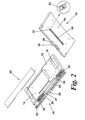
- the actuating mechanism 20 is best seen in Figure 2 and includes a user-operable element 26 (in the form of a slidable element 26) having an actuator button 28, and also includes upper and lower resilient elements 30, 32, which in this embodiment are upper and lower springs 30, 32.
- the sliding element 26 is user actuatable by the actuator button 28 between a lower position ( Figure 3) and an upper position relative ( Figure 4) to the second part 14.
- a cavity 50 is formed at respective upper and lower end to allow the sliding element to move into the lower and upper positions.
- the sliding element 26 includes upper and lower end portions 36, 38 arranged perpendicularly to its direction of travel.
- the upper and lower springs 30, 32 are attached to respective upper and lower end portions 36, 38 and are arranged to oppose one another.
- the arm 34 of the first part 12 is positioned between the end portions 36, 38 and springs 30, 32.
- the first and second parts 12, 14 are in the first configuration and the sliding element 26 is in the lower position.
- the lower spring 32 abuts both the arm 34 and the lower end portion 38 and is uncompressed thereby. In other embodiments there may be a (e.g. modest) degree of compression applied to the spring 32 in this configuration.
- the first and second magnetic elements 16a, 16b of the first bias assembly 16 attract one another and thereby exert a retention force on the first part 12, which force biases the first and second parts 12, 14 towards the first configuration.
- the momentum of the first part 12 carries it towards the second configuration. After the first part 12 reaches the midpoint of its travel, the force exerted by the second bias assembly 18 on the first part 12 assists the movement into the second configuration.
- the first and second parts 12, 14 are in the second configuration and the sliding element 26 is in the upper position.
- the upper spring 30 abuts both the arm 34 and the upper end portion 36 and is uncompressed thereby. In other embodiments there may be a (e.g. modest) degree of compression applied to the spring 30 in this configuration.
- the third and fourth magnetic elements 18a, 18b of the second bias assembly 18 attract one another and thereby exert a retention force on the first part 12, which force biases the first and second parts 12, 14 towards the second configuration.
- the momentum of the first part 12 carries it towards the first configuration. After the first part 12 reaches the midpoint of its travel, the force exerted by the first bias assembly 16 on the first part 12 assists the movement into the first configuration.
- the resilient elements or springs are described as being deformed by compression. Any elastically deformable resilient elements are within the scope of the invention.
- the resilient elements may be resiliently deformable elastic elements which bend when compressive forces are applied and straighten to release compressive forces. It will be appreciated that the resilient elements releasably store energy under compression/tension which is released with the compression/tension is removed.
- the first part 12 may be attachable to an electronic device housing comprising a display and the second part 14 to an electronic device housing comprising one or more user input elements (including a keypad).
- each magnetic/resilient element is each shown to comprise a single member (i.e. a single magnet/spring) it will be appreciated that each magnetic/resilient element may comprise more than member (i.e. more than one magnet/spring).
- Various types of different magnets/springs can be used in combination.
- helical springs are shown in the figures, spiral springs or any suitable springs may be used.
Landscapes
- Engineering & Computer Science (AREA)
- Signal Processing (AREA)
- Telephone Set Structure (AREA)
- Casings For Electric Apparatus (AREA)
Abstract
Description
- The invention relates to a sliding mechanism and in particular to a sliding mechanism for an electronic device. Although specific embodiments may relate to a sliding mechanism for handheld electronic devices comprising radiotelephone functionality, other embodiments may not include radiotelephone functionality. Electronic devices may alternatively or additionally include audio/still image/video recording/playing functionality. Associated methods, including methods of assembly are within the present disclosure.
- Electronic devices, particularly user-portable radiotelephones (e.g. mobile cellular phones), often comprise two separate parts which can be slid between an open configuration in which a keypad, display and/or other user interface elements (including one or more connectivity ports e.g. USB ports) can be accessed and a closed configuration in which the keypad/display and/or other user interface elements are not accessible. More generally, sliding mechanisms for electronic devices allow a compact design facilitating user portability and may not necessarily hide user interface elements in the closed configuration.
- According to the invention, there is provided an electronic device sliding mechanism comprising
a first part and a second part, the first and second parts being slidably movable relative to one another between a first configuration and a second configuration;
a bias assembly arranged to bias the first and second parts towards the first configuration;
an actuating mechanism arrangeable to act against the bias of the bias assembly, the actuating mechanism including a resilient element and a user-operable element, the actuating mechanism being arranged to cause deformation of the resilient element by acting against the resilience of the resilient element, to store resilient energy therein upon actuation of the user-operable element, the sliding mechanism being arranged such that, upon actuation of the user-operable element, the resilient element is deformed to store increased levels of resilient energy, the level of stored resilient energy increasing to a level to act against the bias of the bias assembly to move the first and second parts away from the first configuration to the second configuration. - In a first embodiment, the bias assembly is a first bias assembly, the sliding mechanism further including
a second bias assembly arranged to bias the first and second parts towards the second configuration, the first and second bias assemblies being arranged such that the first and second configurations are bistable configurations of the mechanism. - In the first embodiment, the resilient element may be a first resilient element, and the sliding mechanism may further include
a second resilient element, the actuating mechanism being arranged to cause deformation of the second resilient element by acting against the resilience of the second resilient element, to store resilient energy therein upon actuation of the user-operable element, the sliding mechanism being arranged such that, upon actuation of the user-operable element, the second resilient element is deformed to store increased levels of resilient energy, the level of stored resilient energy increasing to a level to act against the bias of the second bias assembly to move the first and second parts away from the second configuration to the first configuration. - The bias assembly or first bias assembly may include a first magnetic element attached to the first part and a second magnetic element attached the second part, the magnetic elements being arranged to attract one another. Similarly, the second bias assembly may include a third magnetic element attached to the first part and a fourth magnetic element attached the second part, the magnetic elements being arranged to attract one another.
- The user-operable element may include a slidably movable element having an end portion, the resilient element being fixedly attached to the end portion and arranged between the end portion and the first part, such that movement of the slidably movable element when in the first configuration compresses the resilient element against the first part to cause said deformation.
- According to a second aspect, the present invention provides an electronic device comprising the sliding mechanism according to the first aspect.
- According to a third aspect, the present invention provides an electronic device sliding mechanism comprising
a first part and a second part, the first and second parts being slidably movable relative to one another between a first configuration and a second configuration;
a means for biasing arranged to bias the first and second parts towards the first configuration;
a means for actuating arrangeable to act against the bias of the means for biasing, the means for actuating including a means for storing resilient energy and a means for user-operation, the means for actuating being arranged to cause deformation of the means for storing resilient energy by acting against the resilience of the means for storing resilient energy, to store resilient energy therein upon actuation of the means for user-operation, the sliding mechanism being arranged such that, upon actuation of the means for user-operation, the means for storing resilient energy is deformed to store increased levels of resilient energy, the level of stored resilient energy increasing to a level to act against the bias of the means for biasing to move the first and second parts away from the first configuration to the second configuration. - According to a fourth aspect, the present invention provides a electronic device comprising the sliding mechanism according to the third aspect.
- One or more aspects and/or embodiments and/or features from one or more aspects/embodiments in isolation or in various combinations are within the scope of the present disclosure whether or not specifically mentioned in isolation or that combination. Associated methods, including methods of assembly, are within the present disclosure.
- In order that the invention may more readily be understood, a description is now given, by way of example only, reference being made to the accompanying drawings, in which:-
- Figure 1 shows perspective views from above and below an electronic device sliding mechanism according to the invention;
- Figure 2 is a partially exploded view of the sliding mechanism of Figure 1;
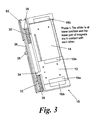
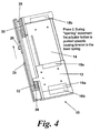
- Figures 3 to 6 show the sliding mechanism of Figure 1 at sequential points during operation of the mechanism;
- Figure 7 shows a typical electronic device in which the sliding mechanism of Figure 1 may be incorporated.
- Figure 1 shows an electronic
device sliding mechanism 10 according to one embodiment of the invention. - In this case, the
sliding mechanism 10 is intended for use with a handheld electronic device, such as a user-portable radiotelephone (e.g. a mobile cellular phone), and includes afirst part 12 and asecond part 14, afirst bias assembly 16 comprising first and secondmagnetic elements magnetic elements actuating mechanism 20. In this embodiment, the magnetic elements are permanent magnets. In other embodiments, the biasing may be provided by electromagnetic elements. The biasing may be provided by electrostatic/magnetic coatings applied to respective surfaces. The bias assembly may be protected by anoverlying metal cover 60. - For ease of understanding, the following description includes relative terms such as "upper" and "lower", but it is to be understood that the function of the
sliding mechanism 10 is not necessarily limited to upper and lower orientations of the device. - The
first part 12 includes aclip 22 which cooperates with aslot 24 in thesecond part 14 to enable thefirst part 12 to be slidably movable relative to thesecond part 14 between a first configuration, shown in Figure 3, and a second configuration, shown in Figure 6. In the first configuration, thefirst part 12 is positioned adjacent the lower end of thesecond part 14 and, in the second configuration, thefirst part 12 is positioned adjacent the upper end of thesecond part 14. As seen in Figure 2, thefirst part 12 includes anarm 34, which will be described below with reference to theactuating mechanism 20. - The first
magnetic element 16a is positioned at the lower end of thefirst part 12 while the secondmagnetic element 16b is positioned at the lower end of thesecond part 14. The first and secondmagnetic elements first bias assembly 16 to bias the first andsecond parts magnetic element 18a is positioned at the upper end of thefirst part 12 while the fourthmagnetic element 18b is positioned at the upper end of thesecond part 14. The third and fourthmagnetic elements second parts sliding mechanism 10. - The
actuating mechanism 20 is best seen in Figure 2 and includes a user-operable element 26 (in the form of a slidable element 26) having anactuator button 28, and also includes upper and lowerresilient elements lower springs sliding element 26 is user actuatable by theactuator button 28 between a lower position (Figure 3) and an upper position relative (Figure 4) to thesecond part 14. Acavity 50 is formed at respective upper and lower end to allow the sliding element to move into the lower and upper positions. - The sliding
element 26 includes upper andlower end portions lower springs lower end portions arm 34 of thefirst part 12 is positioned between theend portions springs - The operation of the sliding mechanism will now be described with reference to Figures 3 to 6.
- In Figure 3, the first and
second parts sliding element 26 is in the lower position. Thelower spring 32 abuts both thearm 34 and thelower end portion 38 and is uncompressed thereby. In other embodiments there may be a (e.g. modest) degree of compression applied to thespring 32 in this configuration. The first and secondmagnetic elements first bias assembly 16 attract one another and thereby exert a retention force on thefirst part 12, which force biases the first andsecond parts - As seen in Figure 4, operation of the
actuator button 28 to move thesliding element 26 to the upper position causes thelower spring 32 to become compressed between thelower end portion 38 and thearm 34 of thefirst part 12. Such compression results in thelower spring 32 exerting a force on the first part 12 (via the arm 34), which force acts against the bias of thefirst bias assembly 16 and tends to move the first andsecond parts first part 12 bylower spring 32 increases until it reaches a level at which it exceeds that exerted on thefirst part 12 by thefirst bias assembly 16, at which point thefirst part 12 moves towards the second configuration, as shown in Figure 5. - The momentum of the
first part 12 carries it towards the second configuration. After thefirst part 12 reaches the midpoint of its travel, the force exerted by the second bias assembly 18 on thefirst part 12 assists the movement into the second configuration. - In Figure 6, the first and
second parts element 26 is in the upper position. Theupper spring 30 abuts both thearm 34 and theupper end portion 36 and is uncompressed thereby.. In other embodiments there may be a (e.g. modest) degree of compression applied to thespring 30 in this configuration. The third and fourthmagnetic elements first part 12, which force biases the first andsecond parts - In the opposite way to that described with reference to Figure 4, operation of the
actuator button 28 to move the slidingelement 26 to the lower position causes theupper spring 30 to become compressed between theupper end portion 36 and thearm 34 of thefirst part 12. Such compression results in theupper spring 30 exerting a force on the first part 12 (via the arm 34), which force acts against the bias of the second bias assembly 18 and tends to move the first andsecond parts first part 12 byupper spring 30 increases until it reaches a level at which it exceeds that exerted on thefirst part 12 by the second bias assembly 18, at which point thefirst part 12 moves towards the first configuration. - The momentum of the
first part 12 carries it towards the first configuration. After thefirst part 12 reaches the midpoint of its travel, the force exerted by thefirst bias assembly 16 on thefirst part 12 assists the movement into the first configuration. - In the above description, the resilient elements or springs are described as being deformed by compression. Any elastically deformable resilient elements are within the scope of the invention. In a variant, the resilient elements may be resiliently deformable elastic elements which bend when compressive forces are applied and straighten to release compressive forces. It will be appreciated that the resilient elements releasably store energy under compression/tension which is released with the compression/tension is removed.
- The
first part 12 may be attachable to an electronic device housing comprising a display and thesecond part 14 to an electronic device housing comprising one or more user input elements (including a keypad). - Although the respective magnetic/resilient elements are each shown to comprise a single member (i.e. a single magnet/spring) it will be appreciated that each magnetic/resilient element may comprise more than member (i.e. more than one magnet/spring). Various types of different magnets/springs can be used in combination. Although helical springs are shown in the figures, spiral springs or any suitable springs may be used.
- The applicant hereby discloses in isolation each individual feature described herein and any combination of two or more such features, to the extent that such features or combinations are capable of being carried out based on the present specification as a whole in the light of the common general knowledge of a person skilled in the art, irrespective of whether such features or combinations of features solve any problems disclosed herein, and without limitation to the scope of the claims. The applicant indicates that aspects of the present invention may comprise any such individual feature or combination of features. In view of the foregoing description it will be evident to a person skilled in the art that various modifications may be made within the scope of the invention.
- While there have been shown and described and pointed out fundamental novel features of the invention as applied to preferred embodiments thereof, it will be understood that various omissions and substitutions and changes in the form and details of the devices and methods described may be made by those skilled in the art without departing from the spirit of the invention. For example, it is expressly intended that all combinations of those elements and/or method steps which perform substantially the same function in substantially the same way to achieve the same results are within the scope of the invention. Moreover, it should be recognized that structures and/or elements and/or method steps shown and/or described in connection with any disclosed form or embodiment of the invention may be incorporated in any other disclosed or described or suggested form or embodiment as a general matter of design choice. It is the intention, therefore, to be limited only as indicated by the scope of the claims appended hereto. Furthermore, in the claims means-plus-function clauses are intended to cover the structures described herein as performing the recited function and not only structural equivalents, but also equivalent structures. Thus although a nail and a screw may not be structural equivalents in that a nail employs a cylindrical surface to secure wooden parts together, whereas a screw employs a helical surface, in the environment of fastening wooden parts, a nail and a screw may be equivalent structures.
Claims (11)
- An electronic device sliding mechanism comprising
a first part and a second part, the first and second parts slidably movable relative to one another between a first configuration and a second configuration;
a bias assembly arranged to bias the first and second parts towards the first configuration;
an actuating mechanism arrangeable to act against the bias of the bias assembly, the actuating mechanism including a resilient element and a user-operable element, the actuating mechanism arranged to cause deformation of the resilient element by acting against resilience of the resilient element, to store resilient energy therein upon actuation of the user-operable element, the sliding mechanism arranged such that, upon actuation of the user-operable element, the resilient element is deformed to store increased levels of resilient energy, the level of stored resilient energy increasing to a level to act against the bias of the bias assembly to move the first and second parts away from the first configuration to the second configuration. - The sliding mechanism of claim 1 wherein the bias assembly is a first bias assembly, the sliding mechanism further including
a second bias assembly arranged to bias the first and second parts towards the second configuration, the first and second bias assemblies being arranged such that the first and second configurations are bistable configurations of the mechanism. - The sliding mechanism of claim 2 wherein the resilient element is a first resilient element, the sliding mechanism further including
a second resilient element, the actuating mechanism being arranged to cause deformation of the second resilient element by acting against resilience of the second resilient element, to store resilient energy therein upon actuation of the user-operable element, the sliding mechanism being arranged such that, upon actuation of the user-operable element, the second resilient element is deformed to store increased levels of resilient energy, the level of stored resilient energy increasing to a level to act against the bias of the second bias assembly to move the first and second parts away from the second configuration to the first configuration. - The sliding mechanism of claim 1 wherein the bias assembly includes a first magnetic element attached to the first part and a second magnetic element attached the second part, the magnetic elements being arranged to attract one another.
- The sliding mechanism of claim 1 wherein the user-operable element includes a slidably movable element having an end portion, the resilient element being fixedly attached to the end portion and arranged between the end portion and the first part, such that movement of the slidably movable element when in the first configuration compresses the resilient element against the first part to cause said deformation.
- An electronic device comprising the sliding mechanism of claim 1.
- An electronic device sliding mechanism comprising
a first part and a second part, the first and second parts being slidably movable relative to one another between a first configuration and a second configuration;
a means for biasing arranged to bias the first and second parts towards the first configuration;
a means for actuating arrangeable to act against the bias of the means for biasing, the means for actuating including a means for storing resilient energy and a means for user-operation, the means for actuating being arranged to cause deformation of the means for storing resilient energy by acting against the resilience of the means for storing resilient energy, to store resilient energy therein upon actuation of the means for user-operation, the sliding mechanism being arranged such that, upon actuation of the means for user-operation, the means for storing resilient energy is deformed to store increased levels of resilient energy, the level of stored resilient energy increasing to a level to act against the bias of the means for biasing to move the first and second parts away from the first configuration to the second configuration. - An electronic device comprising the sliding mechanism of claim 7.
- Method, comprising:slideably moving a first part relative to a second part between a first configuration and a second configuration of a sliding mechanism in response toactuating of an actuating mechanism arranged for action against a bias of a bias assembly for biasing the first and second parts towards the first configuration, said actuating mechanism including a resilient element and a user-operable element, the actuating mechanism arranged to cause deformation of the resilient element by acting against resilience of the resilient element, to store resilient energy therein upon actuation of the user-operable element, the sliding mechanism arranged such that, upon actuation of the user-operable element, the resilient element is deformed to store increased levels of resilient energy, the level of stored resilient energy increasing to a level to act against the bias of the bias assembly to move the first and second parts away from the first configuration to the second configuration.
- Method, comprising:means for slideably moving a first part relative to a second part between a first configuration and a second configuration of a sliding mechanism in response to actuation ofmeans for actuating arranged for action against a bias of a bias assembly for biasing the first and second parts towards the first configuration, said actuating mechanism including a resilient element and a user-operable element, the actuating mechanism arranged to cause deformation of the resilient element by acting against resilience of the resilient element, to store resilient energy therein upon actuation of the user-operable element, the sliding mechanism arranged such that, upon actuation of the user-operable element, the resilient element is deformed to store increased levels of resilient energy, the level of stored resilient energy increasing to a level to act against the bias of the bias assembly to move the first and second parts away from the first configuration to the second configuration.
- A method of assembling an electronic device sliding mechanism, the mechanism comprising
a first part and a second part, the first and second parts slidably movable relative to one another between a first configuration and a second configuration;
a bias assembly arranged to bias the first and second parts towards the first configuration;
an actuating mechanism arrangeable to act against the bias of the bias assembly, the actuating mechanism including a resilient element and a user-operable element, the actuating mechanism arranged to cause deformation of the resilient element by acting against resilience of the resilient element, to store resilient energy therein upon actuation of the user-operable element, the sliding mechanism arranged such that, upon actuation of the user-operable element, the resilient element is deformed to store increased levels of resilient energy, the level of stored resilient energy increasing to a level to act against the bias of the bias assembly to move the first and second parts away from the first configuration to the second configuration, wherein the method comprises assembling the first and second parts with the bias assembly and actuating mechanism such that upon actuation of the user-operable element, the resilient element is deformed to store increased levels of resilient energy, the level of stored resilient energy increasing to a level to act against the bias of the bias assembly to move the first and second parts away from the first configuration to the second configuration.
Applications Claiming Priority (1)
| Application Number | Priority Date | Filing Date | Title |
|---|---|---|---|
| US11/440,710 US7515930B2 (en) | 2006-05-24 | 2006-05-24 | Electronic device sliding mechanism |
Publications (2)
| Publication Number | Publication Date |
|---|---|
| EP1860848A1 true EP1860848A1 (en) | 2007-11-28 |
| EP1860848B1 EP1860848B1 (en) | 2010-08-18 |
Family
ID=38476017
Family Applications (1)
| Application Number | Title | Priority Date | Filing Date |
|---|---|---|---|
| EP07252106A Active EP1860848B1 (en) | 2006-05-24 | 2007-05-22 | An electronic device sliding mechanism comprising a magnetic bias assembly and an actuating mechanism acting against the bias assembly |
Country Status (5)
| Country | Link |
|---|---|
| US (1) | US7515930B2 (en) |
| EP (1) | EP1860848B1 (en) |
| CN (1) | CN101106884B (en) |
| AT (1) | ATE478514T1 (en) |
| DE (1) | DE602007008500D1 (en) |
Cited By (3)
| Publication number | Priority date | Publication date | Assignee | Title |
|---|---|---|---|---|
| WO2010089298A1 (en) * | 2009-02-05 | 2010-08-12 | Nokia Corporation | Magnetic actuation mechanism |
| EP2288116A1 (en) * | 2009-08-18 | 2011-02-23 | King Slide Works Co., Ltd. | Operation device for controlling sliding cover of portable electronic product |
| CN101730422B (en) * | 2008-10-14 | 2012-06-13 | 庆良电子股份有限公司 | Electromagnetic sliding mechanism and electronic device |
Families Citing this family (72)
| Publication number | Priority date | Publication date | Assignee | Title |
|---|---|---|---|---|
| TW200742390A (en) * | 2006-04-28 | 2007-11-01 | Benq Corp | Sliding mechanism for moving electronic device |
| US8046039B2 (en) * | 2006-10-20 | 2011-10-25 | Lg Electronics Inc. | Mobile terminal and case for mobile terminal |
| KR101164607B1 (en) * | 2006-11-22 | 2012-07-10 | 삼성테크윈 주식회사 | Sliding structure for mobile electronic device |
| TWI333774B (en) * | 2007-02-05 | 2010-11-21 | Asustek Comp Inc | Slidable cell phone |
| CN101359779B (en) * | 2007-08-03 | 2011-03-23 | 深圳富泰宏精密工业有限公司 | Earthing device of portable electronic apparatus |
| CN101453853B (en) * | 2007-12-07 | 2012-03-14 | 鸿富锦精密工业(深圳)有限公司 | Sliding mechanism |
| US20090209306A1 (en) * | 2008-02-19 | 2009-08-20 | Research In Motion Limited | Multi-function slide mechanism for a mobile communication device |
| CN101742858B (en) * | 2008-11-17 | 2012-10-17 | 深圳富泰宏精密工业有限公司 | Slide-cover electronic device |
| USD609701S1 (en) * | 2008-11-20 | 2010-02-09 | Cheng Uei Precision Industry Co., Ltd. | Wireless transceiver |
| CN101742848B (en) * | 2008-11-26 | 2013-05-29 | 深圳富泰宏精密工业有限公司 | Portable electronic device |
| CN101995732A (en) * | 2009-08-21 | 2011-03-30 | 深圳富泰宏精密工业有限公司 | Lens cap positioning component and lens cap mechanism with same |
| USD641371S1 (en) * | 2009-12-21 | 2011-07-12 | Research In Motion Limited | Keyboard |
| USD644235S1 (en) * | 2010-01-19 | 2011-08-30 | Research In Motin Limited | Handheld electronic device |
| USD635577S1 (en) * | 2010-04-30 | 2011-04-05 | Research In Motion Limited | Keyboard |
| USD635578S1 (en) * | 2010-04-30 | 2011-04-05 | Research In Motion Limited | Keyboard |
| USD635146S1 (en) * | 2010-04-30 | 2011-03-29 | Research In Motion Limited | Keyboard |
| USD635982S1 (en) * | 2010-04-30 | 2011-04-12 | Research In Motion Limited | Keyboard |
| USD635984S1 (en) * | 2010-04-30 | 2011-04-12 | Research In Motion Limited | Keyboard |
| USD635981S1 (en) * | 2010-04-30 | 2011-04-12 | Research In Motion Limited | Keyboard |
| USD635985S1 (en) * | 2010-04-30 | 2011-04-12 | Research In Motion Limited | Keyboard |
| USD635144S1 (en) * | 2010-04-30 | 2011-03-29 | Research In Motion Limited | Keyboard |
| USD635145S1 (en) * | 2010-04-30 | 2011-03-29 | Research In Motion Limited | Keyboard |
| USD644233S1 (en) * | 2010-07-12 | 2011-08-30 | Research In Motion Limited | Keyboard |
| USD644234S1 (en) * | 2010-07-12 | 2011-08-30 | Research In Motion Limited | Keyboard |
| USD641757S1 (en) * | 2010-07-12 | 2011-07-19 | Research In Motion Limited | Keyboard |
| USD641760S1 (en) * | 2010-07-12 | 2011-07-19 | Research In Motion Limited | Keyboard |
| USD644232S1 (en) * | 2010-07-12 | 2011-08-30 | Research In Motion Limited | Keyboard |
| USD640259S1 (en) * | 2010-07-12 | 2011-06-21 | Research In Motion Limited | Keyboard |
| USD644231S1 (en) * | 2010-07-12 | 2011-08-30 | Research In Motion Limited | Keyboard |
| USD641758S1 (en) * | 2010-07-12 | 2011-07-19 | Research In Motion Limited | Keyboard |
| USD641759S1 (en) * | 2010-07-12 | 2011-07-19 | Research In Motion Limited | Keyboard |
| USD641761S1 (en) * | 2010-07-12 | 2011-07-19 | Research In Motion Limited | Keyboard |
| USD635983S1 (en) * | 2010-10-25 | 2011-04-12 | Research In Motion Limited | Keyboard |
| USD660853S1 (en) * | 2011-04-06 | 2012-05-29 | Research In Motion Limited | Keyboard |
| USD660848S1 (en) * | 2011-04-06 | 2012-05-29 | Research In Motion Limited | Keyboard |
| USD660847S1 (en) * | 2011-04-06 | 2012-05-29 | Research In Motion Limited | Keyboard |
| USD660854S1 (en) * | 2011-04-06 | 2012-05-29 | Research In Motion Limited | Keyboard |
| USD660846S1 (en) * | 2011-04-06 | 2012-05-29 | Research In Motion Limited | Keyboard |
| USD660849S1 (en) * | 2011-04-06 | 2012-05-29 | Research In Motion Limited | Keyboard |
| USD660852S1 (en) * | 2011-04-06 | 2012-05-29 | Research In Motion Limited | Keyboard |
| USD666624S1 (en) * | 2011-04-06 | 2012-09-04 | Research In Motion Limited | Keyboard |
| USD660855S1 (en) * | 2011-04-06 | 2012-05-29 | Research In Motion Limited | Keyboard |
| USD660850S1 (en) * | 2011-04-06 | 2012-05-29 | Research In Motion Limited | Keyboard |
| USD667014S1 (en) * | 2011-04-06 | 2012-09-11 | Research In Motion Limited | Keyboard |
| USD660851S1 (en) * | 2011-04-06 | 2012-05-29 | Research In Motion Limited | Keyboard |
| USD658661S1 (en) * | 2011-05-12 | 2012-05-01 | Research In Motion Limited | Keyboard |
| USD658660S1 (en) * | 2011-05-12 | 2012-05-01 | Research In Motion Limited | Keyboard |
| USD659702S1 (en) * | 2011-05-12 | 2012-05-15 | Research In Motion Limited | Keyboard |
| USD658659S1 (en) * | 2011-05-12 | 2012-05-01 | Research In Motion Limited | Keyboard |
| USD658656S1 (en) * | 2011-05-12 | 2012-05-01 | Research In Motion Limited | Keyboard |
| USD658662S1 (en) * | 2011-05-12 | 2012-05-01 | Research In Motion Limited | Keyboard |
| USD659701S1 (en) * | 2011-05-12 | 2012-05-15 | Research In Motion Limited | Keyboard |
| USD658653S1 (en) * | 2011-05-12 | 2012-05-01 | Research In Motion Limited | Keyboard |
| USD658655S1 (en) * | 2011-05-12 | 2012-05-01 | Research In Motion Limited | Keyboard |
| USD658658S1 (en) * | 2011-05-12 | 2012-05-01 | Research In Motion Limited | Keyboard |
| USD658657S1 (en) * | 2011-05-12 | 2012-05-01 | Research In Motion Limited | Keyboard |
| USD659703S1 (en) * | 2011-05-12 | 2012-05-15 | Research In Motion Limited | Keyboard |
| USD658654S1 (en) * | 2011-05-12 | 2012-05-01 | Research In Motion Limited | Keyboard |
| USD659700S1 (en) * | 2011-05-12 | 2012-05-15 | Research In Motion Limited | Keyboard |
| USD671547S1 (en) * | 2011-09-02 | 2012-11-27 | Research In Motion Limited | Keyboard |
| USD670710S1 (en) * | 2011-11-18 | 2012-11-13 | Research In Motion Limited | Keyboard |
| USD670709S1 (en) * | 2011-11-18 | 2012-11-13 | Research In Motion Limited | Keyboard |
| USD672358S1 (en) * | 2011-11-18 | 2012-12-11 | Research In Motion Limited | Keyboard |
| USD670707S1 (en) * | 2011-11-18 | 2012-11-13 | Research In Motion Limited | Keyboard |
| USD670705S1 (en) * | 2011-11-18 | 2012-11-13 | Research In Motion Limited | Keyboard |
| USD670706S1 (en) * | 2011-11-18 | 2012-11-13 | Research In Motion Limited | Keyboard |
| USD672359S1 (en) * | 2011-11-18 | 2012-12-11 | Research In Motion Limited | Keyboard |
| USD670708S1 (en) * | 2011-11-18 | 2012-11-13 | Research In Motion Limited | Keyboard |
| USD700189S1 (en) * | 2012-12-05 | 2014-02-25 | Blackberry Limited | Keyboard |
| USD746826S1 (en) * | 2012-12-05 | 2016-01-05 | Blackberry Limited | Keyboard |
| CN113596203A (en) * | 2021-07-19 | 2021-11-02 | 武汉华星光电半导体显示技术有限公司 | Display device |
| CN113689791B (en) * | 2021-08-24 | 2023-08-01 | 武汉华星光电半导体显示技术有限公司 | Display device and display equipment |
Citations (3)
| Publication number | Priority date | Publication date | Assignee | Title |
|---|---|---|---|---|
| EP0939533A2 (en) * | 1998-02-27 | 1999-09-01 | Nokia Mobile Phones Ltd. | Slide cover for a communication unit |
| EP1150476A2 (en) * | 2000-04-28 | 2001-10-31 | Nokia Mobile Phones Ltd. | Telescopic structure for a telephone apparatus |
| WO2006031078A1 (en) * | 2004-09-15 | 2006-03-23 | M2Sys Co., Ltd | A sliding mechanism for opening and closing of cellular phone |
Family Cites Families (11)
| Publication number | Priority date | Publication date | Assignee | Title |
|---|---|---|---|---|
| JP3944506B2 (en) * | 2003-10-28 | 2007-07-11 | エルジー エレクトロニクス インコーポレイティド | SLIDING TYPE PORTABLE TERMINAL AND SLIDING DEVICE USED FOR THE SAME |
| KR100617690B1 (en) * | 2003-11-10 | 2006-08-28 | 삼성전자주식회사 | Sliding type portable wireless terminal |
| JP2005210649A (en) * | 2004-01-26 | 2005-08-04 | Kato Electrical Mach Co Ltd | Sliding mechanism of mobile terminal |
| TWM260061U (en) * | 2004-06-11 | 2005-03-21 | Quanta Comp Inc | Automatic sliding mechanism |
| JP4509182B2 (en) * | 2004-07-08 | 2010-07-21 | ハイテック パーツ カンパニー リミテッド | Slider assembly for slide type mobile phone and slide type mobile phone |
| US7181257B2 (en) * | 2004-12-28 | 2007-02-20 | Motorola, Inc. | Slider mechanism for handheld devices |
| JP4530218B2 (en) * | 2005-03-07 | 2010-08-25 | ソニー・エリクソン・モバイルコミュニケーションズ株式会社 | Mobile terminal device |
| US20070060220A1 (en) * | 2005-09-14 | 2007-03-15 | An-Szu Hsu | Gliding structure for glide-open type mobile phone |
| CN101248585B (en) * | 2005-09-23 | 2011-01-26 | 安费诺凤凰株式会社 | Sliding opening and closing device for use in portable telephones |
| US20070155448A1 (en) * | 2006-01-04 | 2007-07-05 | Jia-Sing Hong | Sliding mechanism of handheld electronic device |
| CN101039339A (en) * | 2006-03-14 | 2007-09-19 | 德铃电子株式会社 | Sliding apparatus and mobile phone having the same |
-
2006
- 2006-05-24 US US11/440,710 patent/US7515930B2/en active Active
-
2007
- 2007-05-22 EP EP07252106A patent/EP1860848B1/en active Active
- 2007-05-22 DE DE602007008500T patent/DE602007008500D1/en active Active
- 2007-05-22 AT AT07252106T patent/ATE478514T1/en not_active IP Right Cessation
- 2007-05-24 CN CN2007101055209A patent/CN101106884B/en active Active
Patent Citations (3)
| Publication number | Priority date | Publication date | Assignee | Title |
|---|---|---|---|---|
| EP0939533A2 (en) * | 1998-02-27 | 1999-09-01 | Nokia Mobile Phones Ltd. | Slide cover for a communication unit |
| EP1150476A2 (en) * | 2000-04-28 | 2001-10-31 | Nokia Mobile Phones Ltd. | Telescopic structure for a telephone apparatus |
| WO2006031078A1 (en) * | 2004-09-15 | 2006-03-23 | M2Sys Co., Ltd | A sliding mechanism for opening and closing of cellular phone |
Cited By (3)
| Publication number | Priority date | Publication date | Assignee | Title |
|---|---|---|---|---|
| CN101730422B (en) * | 2008-10-14 | 2012-06-13 | 庆良电子股份有限公司 | Electromagnetic sliding mechanism and electronic device |
| WO2010089298A1 (en) * | 2009-02-05 | 2010-08-12 | Nokia Corporation | Magnetic actuation mechanism |
| EP2288116A1 (en) * | 2009-08-18 | 2011-02-23 | King Slide Works Co., Ltd. | Operation device for controlling sliding cover of portable electronic product |
Also Published As
| Publication number | Publication date |
|---|---|
| EP1860848B1 (en) | 2010-08-18 |
| CN101106884A (en) | 2008-01-16 |
| US7515930B2 (en) | 2009-04-07 |
| CN101106884B (en) | 2010-06-09 |
| DE602007008500D1 (en) | 2010-09-30 |
| US20070273293A1 (en) | 2007-11-29 |
| ATE478514T1 (en) | 2010-09-15 |
Similar Documents
| Publication | Publication Date | Title |
|---|---|---|
| US7515930B2 (en) | Electronic device sliding mechanism | |
| EP1858234A2 (en) | An electronic device sliding mechanism comprising magnetic elements to bias the device to a given position | |
| KR100661059B1 (en) | slide me?hanism for a portable terminal | |
| US7751181B2 (en) | Battery cover assembly for portable electronic device | |
| US8254116B2 (en) | Tilting portable electronic device | |
| US8304101B2 (en) | Battery cover latching mechanism for portable electronic device | |
| JP2008154197A (en) | Sliding mechanism and portable electronic device using the same | |
| US20090260183A1 (en) | Hinge assembly for foldable electronic devices | |
| US7697280B2 (en) | Sliding mechanism for portable electronic device | |
| EP1830542A2 (en) | Spring loaded sliding mechanism for a portable electronic device | |
| KR100679006B1 (en) | Slide device and mobile phone of mobile device | |
| US8299383B2 (en) | Push switch | |
| JP4638937B2 (en) | Slide type hinge mechanism | |
| US8428668B2 (en) | Sliding mechanism | |
| US8249673B2 (en) | Sliding-type portable electronic device | |
| US8249675B2 (en) | Slide type electronic device | |
| US8411464B2 (en) | Portable electronic device with rotatable cover | |
| US20070004395A1 (en) | Slide mechanism for a slide-type portable terminal device | |
| CN216487785U (en) | Terminal Equipment | |
| US8213600B2 (en) | Sliding mechanism | |
| EP2290917B1 (en) | Handheld electronic device | |
| EP2146489A1 (en) | Portable terminal with keypad lifting mechanism | |
| KR200417445Y1 (en) | Slide module for mobile terminal | |
| KR101020442B1 (en) | Slide switch of portable terminal | |
| US20060120713A1 (en) | Semiautomatic cover-sliding structure |
Legal Events
| Date | Code | Title | Description |
|---|---|---|---|
| PUAI | Public reference made under article 153(3) epc to a published international application that has entered the european phase |
Free format text: ORIGINAL CODE: 0009012 |
|
| 17P | Request for examination filed |
Effective date: 20070601 |
|
| AK | Designated contracting states |
Kind code of ref document: A1 Designated state(s): AT BE BG CH CY CZ DE DK EE ES FI FR GB GR HU IE IS IT LI LT LU LV MC MT NL PL PT RO SE SI SK TR |
|
| AX | Request for extension of the european patent |
Extension state: AL BA HR MK YU |
|
| 17Q | First examination report despatched |
Effective date: 20080618 |
|
| AKX | Designation fees paid |
Designated state(s): AT BE BG CH CY CZ DE DK EE ES FI FR GB GR HU IE IS IT LI LT LU LV MC MT NL PL PT RO SE SI SK TR |
|
| GRAP | Despatch of communication of intention to grant a patent |
Free format text: ORIGINAL CODE: EPIDOSNIGR1 |
|
| RIN1 | Information on inventor provided before grant (corrected) |
Inventor name: EROMAKI MARKO |
|
| GRAS | Grant fee paid |
Free format text: ORIGINAL CODE: EPIDOSNIGR3 |
|
| GRAA | (expected) grant |
Free format text: ORIGINAL CODE: 0009210 |
|
| AK | Designated contracting states |
Kind code of ref document: B1 Designated state(s): AT BE BG CH CY CZ DE DK EE ES FI FR GB GR HU IE IS IT LI LT LU LV MC MT NL PL PT RO SE SI SK TR |
|
| REG | Reference to a national code |
Ref country code: GB Ref legal event code: FG4D |
|
| REG | Reference to a national code |
Ref country code: CH Ref legal event code: EP |
|
| REG | Reference to a national code |
Ref country code: IE Ref legal event code: FG4D |
|
| REF | Corresponds to: |
Ref document number: 602007008500 Country of ref document: DE Date of ref document: 20100930 Kind code of ref document: P |
|
| REG | Reference to a national code |
Ref country code: NL Ref legal event code: VDEP Effective date: 20100818 |
|
| LTIE | Lt: invalidation of european patent or patent extension |
Effective date: 20100818 |
|
| PG25 | Lapsed in a contracting state [announced via postgrant information from national office to epo] |
Ref country code: FI Free format text: LAPSE BECAUSE OF FAILURE TO SUBMIT A TRANSLATION OF THE DESCRIPTION OR TO PAY THE FEE WITHIN THE PRESCRIBED TIME-LIMIT Effective date: 20100818 Ref country code: LT Free format text: LAPSE BECAUSE OF FAILURE TO SUBMIT A TRANSLATION OF THE DESCRIPTION OR TO PAY THE FEE WITHIN THE PRESCRIBED TIME-LIMIT Effective date: 20100818 Ref country code: AT Free format text: LAPSE BECAUSE OF FAILURE TO SUBMIT A TRANSLATION OF THE DESCRIPTION OR TO PAY THE FEE WITHIN THE PRESCRIBED TIME-LIMIT Effective date: 20100818 |
|
| PG25 | Lapsed in a contracting state [announced via postgrant information from national office to epo] |
Ref country code: IS Free format text: LAPSE BECAUSE OF FAILURE TO SUBMIT A TRANSLATION OF THE DESCRIPTION OR TO PAY THE FEE WITHIN THE PRESCRIBED TIME-LIMIT Effective date: 20101218 Ref country code: BG Free format text: LAPSE BECAUSE OF FAILURE TO SUBMIT A TRANSLATION OF THE DESCRIPTION OR TO PAY THE FEE WITHIN THE PRESCRIBED TIME-LIMIT Effective date: 20101118 Ref country code: CY Free format text: LAPSE BECAUSE OF FAILURE TO SUBMIT A TRANSLATION OF THE DESCRIPTION OR TO PAY THE FEE WITHIN THE PRESCRIBED TIME-LIMIT Effective date: 20100818 Ref country code: PL Free format text: LAPSE BECAUSE OF FAILURE TO SUBMIT A TRANSLATION OF THE DESCRIPTION OR TO PAY THE FEE WITHIN THE PRESCRIBED TIME-LIMIT Effective date: 20100818 Ref country code: PT Free format text: LAPSE BECAUSE OF FAILURE TO SUBMIT A TRANSLATION OF THE DESCRIPTION OR TO PAY THE FEE WITHIN THE PRESCRIBED TIME-LIMIT Effective date: 20101220 Ref country code: SI Free format text: LAPSE BECAUSE OF FAILURE TO SUBMIT A TRANSLATION OF THE DESCRIPTION OR TO PAY THE FEE WITHIN THE PRESCRIBED TIME-LIMIT Effective date: 20100818 |
|
| PG25 | Lapsed in a contracting state [announced via postgrant information from national office to epo] |
Ref country code: SE Free format text: LAPSE BECAUSE OF FAILURE TO SUBMIT A TRANSLATION OF THE DESCRIPTION OR TO PAY THE FEE WITHIN THE PRESCRIBED TIME-LIMIT Effective date: 20100818 Ref country code: NL Free format text: LAPSE BECAUSE OF FAILURE TO SUBMIT A TRANSLATION OF THE DESCRIPTION OR TO PAY THE FEE WITHIN THE PRESCRIBED TIME-LIMIT Effective date: 20100818 Ref country code: BE Free format text: LAPSE BECAUSE OF FAILURE TO SUBMIT A TRANSLATION OF THE DESCRIPTION OR TO PAY THE FEE WITHIN THE PRESCRIBED TIME-LIMIT Effective date: 20100818 Ref country code: LV Free format text: LAPSE BECAUSE OF FAILURE TO SUBMIT A TRANSLATION OF THE DESCRIPTION OR TO PAY THE FEE WITHIN THE PRESCRIBED TIME-LIMIT Effective date: 20100818 Ref country code: GR Free format text: LAPSE BECAUSE OF FAILURE TO SUBMIT A TRANSLATION OF THE DESCRIPTION OR TO PAY THE FEE WITHIN THE PRESCRIBED TIME-LIMIT Effective date: 20101119 |
|
| PG25 | Lapsed in a contracting state [announced via postgrant information from national office to epo] |
Ref country code: DK Free format text: LAPSE BECAUSE OF FAILURE TO SUBMIT A TRANSLATION OF THE DESCRIPTION OR TO PAY THE FEE WITHIN THE PRESCRIBED TIME-LIMIT Effective date: 20100818 |
|
| PG25 | Lapsed in a contracting state [announced via postgrant information from national office to epo] |
Ref country code: RO Free format text: LAPSE BECAUSE OF FAILURE TO SUBMIT A TRANSLATION OF THE DESCRIPTION OR TO PAY THE FEE WITHIN THE PRESCRIBED TIME-LIMIT Effective date: 20100818 Ref country code: SK Free format text: LAPSE BECAUSE OF FAILURE TO SUBMIT A TRANSLATION OF THE DESCRIPTION OR TO PAY THE FEE WITHIN THE PRESCRIBED TIME-LIMIT Effective date: 20100818 Ref country code: CZ Free format text: LAPSE BECAUSE OF FAILURE TO SUBMIT A TRANSLATION OF THE DESCRIPTION OR TO PAY THE FEE WITHIN THE PRESCRIBED TIME-LIMIT Effective date: 20100818 Ref country code: EE Free format text: LAPSE BECAUSE OF FAILURE TO SUBMIT A TRANSLATION OF THE DESCRIPTION OR TO PAY THE FEE WITHIN THE PRESCRIBED TIME-LIMIT Effective date: 20100818 Ref country code: IT Free format text: LAPSE BECAUSE OF FAILURE TO SUBMIT A TRANSLATION OF THE DESCRIPTION OR TO PAY THE FEE WITHIN THE PRESCRIBED TIME-LIMIT Effective date: 20100818 |
|
| PLBE | No opposition filed within time limit |
Free format text: ORIGINAL CODE: 0009261 |
|
| STAA | Information on the status of an ep patent application or granted ep patent |
Free format text: STATUS: NO OPPOSITION FILED WITHIN TIME LIMIT |
|
| PG25 | Lapsed in a contracting state [announced via postgrant information from national office to epo] |
Ref country code: ES Free format text: LAPSE BECAUSE OF FAILURE TO SUBMIT A TRANSLATION OF THE DESCRIPTION OR TO PAY THE FEE WITHIN THE PRESCRIBED TIME-LIMIT Effective date: 20101129 |
|
| 26N | No opposition filed |
Effective date: 20110519 |
|
| PGFP | Annual fee paid to national office [announced via postgrant information from national office to epo] |
Ref country code: GB Payment date: 20110518 Year of fee payment: 5 |
|
| REG | Reference to a national code |
Ref country code: DE Ref legal event code: R097 Ref document number: 602007008500 Country of ref document: DE Effective date: 20110519 |
|
| PG25 | Lapsed in a contracting state [announced via postgrant information from national office to epo] |
Ref country code: MC Free format text: LAPSE BECAUSE OF NON-PAYMENT OF DUE FEES Effective date: 20110531 Ref country code: MT Free format text: LAPSE BECAUSE OF FAILURE TO SUBMIT A TRANSLATION OF THE DESCRIPTION OR TO PAY THE FEE WITHIN THE PRESCRIBED TIME-LIMIT Effective date: 20100818 |
|
| REG | Reference to a national code |
Ref country code: CH Ref legal event code: PL |
|
| PG25 | Lapsed in a contracting state [announced via postgrant information from national office to epo] |
Ref country code: CH Free format text: LAPSE BECAUSE OF NON-PAYMENT OF DUE FEES Effective date: 20110531 Ref country code: LI Free format text: LAPSE BECAUSE OF NON-PAYMENT OF DUE FEES Effective date: 20110531 |
|
| REG | Reference to a national code |
Ref country code: FR Ref legal event code: ST Effective date: 20120131 |
|
| REG | Reference to a national code |
Ref country code: IE Ref legal event code: MM4A |
|
| PG25 | Lapsed in a contracting state [announced via postgrant information from national office to epo] |
Ref country code: FR Free format text: LAPSE BECAUSE OF NON-PAYMENT OF DUE FEES Effective date: 20110531 Ref country code: IE Free format text: LAPSE BECAUSE OF NON-PAYMENT OF DUE FEES Effective date: 20110522 |
|
| GBPC | Gb: european patent ceased through non-payment of renewal fee |
Effective date: 20120522 |
|
| PG25 | Lapsed in a contracting state [announced via postgrant information from national office to epo] |
Ref country code: GB Free format text: LAPSE BECAUSE OF NON-PAYMENT OF DUE FEES Effective date: 20120522 |
|
| PG25 | Lapsed in a contracting state [announced via postgrant information from national office to epo] |
Ref country code: LU Free format text: LAPSE BECAUSE OF NON-PAYMENT OF DUE FEES Effective date: 20110522 |
|
| PG25 | Lapsed in a contracting state [announced via postgrant information from national office to epo] |
Ref country code: TR Free format text: LAPSE BECAUSE OF FAILURE TO SUBMIT A TRANSLATION OF THE DESCRIPTION OR TO PAY THE FEE WITHIN THE PRESCRIBED TIME-LIMIT Effective date: 20100818 |
|
| PG25 | Lapsed in a contracting state [announced via postgrant information from national office to epo] |
Ref country code: HU Free format text: LAPSE BECAUSE OF FAILURE TO SUBMIT A TRANSLATION OF THE DESCRIPTION OR TO PAY THE FEE WITHIN THE PRESCRIBED TIME-LIMIT Effective date: 20100818 |
|
| REG | Reference to a national code |
Ref country code: DE Ref legal event code: R081 Ref document number: 602007008500 Country of ref document: DE Owner name: NOKIA TECHNOLOGIES OY, FI Free format text: FORMER OWNER: NOKIA CORP., 02610 ESPOO, FI |
|
| REG | Reference to a national code |
Ref country code: DE Ref legal event code: R081 Ref document number: 602007008500 Country of ref document: DE Owner name: VIVO MOBILE COMMUNICATION CO., LTD., DONGGUAN, CN Free format text: FORMER OWNER: NOKIA TECHNOLOGIES OY, ESPOO, FI |
|
| P01 | Opt-out of the competence of the unified patent court (upc) registered |
Effective date: 20230526 |
|
| PGFP | Annual fee paid to national office [announced via postgrant information from national office to epo] |
Ref country code: DE Payment date: 20250402 Year of fee payment: 19 |