EP1860497A2 - Projector and lamp module - Google Patents
Projector and lamp module Download PDFInfo
- Publication number
- EP1860497A2 EP1860497A2 EP07010164A EP07010164A EP1860497A2 EP 1860497 A2 EP1860497 A2 EP 1860497A2 EP 07010164 A EP07010164 A EP 07010164A EP 07010164 A EP07010164 A EP 07010164A EP 1860497 A2 EP1860497 A2 EP 1860497A2
- Authority
- EP
- European Patent Office
- Prior art keywords
- lamp module
- enclosure
- lamp
- ribs
- projector
- Prior art date
- Legal status (The legal status is an assumption and is not a legal conclusion. Google has not performed a legal analysis and makes no representation as to the accuracy of the status listed.)
- Withdrawn
Links
- 230000003287 optical effect Effects 0.000 claims description 37
- 230000035939 shock Effects 0.000 description 8
- 238000010586 diagram Methods 0.000 description 5
- 238000000034 method Methods 0.000 description 5
- 238000005286 illumination Methods 0.000 description 3
- 238000004519 manufacturing process Methods 0.000 description 3
- 230000005236 sound signal Effects 0.000 description 3
- FYYHWMGAXLPEAU-UHFFFAOYSA-N Magnesium Chemical compound [Mg] FYYHWMGAXLPEAU-UHFFFAOYSA-N 0.000 description 2
- 239000003086 colorant Substances 0.000 description 2
- 238000007796 conventional method Methods 0.000 description 2
- 229910052749 magnesium Inorganic materials 0.000 description 2
- 239000011777 magnesium Substances 0.000 description 2
- 238000012937 correction Methods 0.000 description 1
- 230000007547 defect Effects 0.000 description 1
- 238000013461 design Methods 0.000 description 1
- 230000000694 effects Effects 0.000 description 1
- 238000005516 engineering process Methods 0.000 description 1
- 230000002452 interceptive effect Effects 0.000 description 1
- 239000000463 material Substances 0.000 description 1
- 238000012545 processing Methods 0.000 description 1
- 239000011347 resin Substances 0.000 description 1
- 229920005989 resin Polymers 0.000 description 1
- 230000000717 retained effect Effects 0.000 description 1
- 238000007493 shaping process Methods 0.000 description 1
Images



Classifications
-
- G—PHYSICS
- G03—PHOTOGRAPHY; CINEMATOGRAPHY; ANALOGOUS TECHNIQUES USING WAVES OTHER THAN OPTICAL WAVES; ELECTROGRAPHY; HOLOGRAPHY
- G03B—APPARATUS OR ARRANGEMENTS FOR TAKING PHOTOGRAPHS OR FOR PROJECTING OR VIEWING THEM; APPARATUS OR ARRANGEMENTS EMPLOYING ANALOGOUS TECHNIQUES USING WAVES OTHER THAN OPTICAL WAVES; ACCESSORIES THEREFOR
- G03B21/00—Projectors or projection-type viewers; Accessories therefor
- G03B21/14—Details
- G03B21/145—Housing details, e.g. position adjustments thereof
-
- G—PHYSICS
- G03—PHOTOGRAPHY; CINEMATOGRAPHY; ANALOGOUS TECHNIQUES USING WAVES OTHER THAN OPTICAL WAVES; ELECTROGRAPHY; HOLOGRAPHY
- G03B—APPARATUS OR ARRANGEMENTS FOR TAKING PHOTOGRAPHS OR FOR PROJECTING OR VIEWING THEM; APPARATUS OR ARRANGEMENTS EMPLOYING ANALOGOUS TECHNIQUES USING WAVES OTHER THAN OPTICAL WAVES; ACCESSORIES THEREFOR
- G03B21/00—Projectors or projection-type viewers; Accessories therefor
- G03B21/14—Details
- G03B21/20—Lamp housings
- G03B21/2046—Positional adjustment of light sources
Definitions
- the present invention relates to a projector.
- FIG. 8 is a block diagram of a conventional projector.
- a projector 1 is configured of a lamp module 3 having received therein a lamp 3a as a light source disposed toward the front face side of an enclosure 2, an engine module 4 generating an image on the basis of light from the lamp, and a projecting lens 5 for projecting the image generated by the engine module 4.
- Light emitted from the lamp 3a as the light source is passed through the engine module 4 and a DMD 4a to be finally projected from the projecting lens 5. Therefore, the lamp module 3 for fixing the lamp 3a to the enclosure 2 is required to be securely fixed to the enclosure 2 so that the optical axis of light emitted from the light source may not deviate from the right path.
- the invention disclosed in the patent document 2 is just for facilitating removal of the lamp module from the enclosure and therefore the deviation of the optical axis of light emitted from the lamp module cannot be prevented.
- a screw passed through a boss is engaged with a female screw in a socket portion, and thus, a lamp module, with its movement in a horizontal plane controlled, is received into a lamp module receiving portion.
- the lamp module is controlled in its vertical movement by a first rib formed on the bottom face of the lamp module receiving portion and second ribs formed on the lid. In this way, the lamp module is controlled in its movement in the horizontal direction and vertical direction and an optical axis of light emitted from the lamp module is fixed.
- a lamp module is controlled in its movement in a horizontal plane by having positioning pins inserted into positioning holes provided in a vertical direction in an enclosure and further the lamp module is received into the enclosure as supported vertically between a first rib and second ribs formed on the ceiling face and the bottom face of the enclosure, and therefore, the configuration can fix the lamp module within the enclosure by a simple structure and, even if it is subjected to a shock, it prevents the optical axis from deviating easily by virtue of the positioning pins and screw.
- the second ribs are formed on the lid member serving as the bottom face. Therefore, when the second ribs are formed, they can be formed separate from the main body side of the enclosure. Thus, manufacturing of the enclosure having the first rib and the second ribs thereon can be made easier.
- each of the second ribs is formed to have a U-shaped cross-section. Accordingly, when subjected to a shock, the impulse can be absorbed by the U-shaped cross-section and, further, the shape of the bottom plate of the enclosure is prevented from producing deformation due to shrinkage during the manufacture of the second ribs.
- a small gap is formed between the lamp module and the first rib, and therefore, when the lamp module is assembled into the enclosure, a deviation of the optical axis due to interference between the first rib and the lamp module can be prevented.
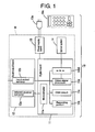
- FIG. 1 is a block configuration diagram of the projector 10 according to the present invention.
- the projector 10 has a box type enclosure 16.
- the enclosure 16 accommodates an optical system 14 for projecting an image by the use of light from a lamp, a digital board 11 for controlling the optical system 14, a power supply board 13 for providing the digital board 11 with necessary power supply, and an input-output board 12 for receiving a video signal and an audio signal from external equipment such as a personal computer and also accepting an operating signal transmitted from a remote controller 10a.
- an optical system 14 for projecting an image by the use of light from a lamp
- a digital board 11 for controlling the optical system 14
- a power supply board 13 for providing the digital board 11 with necessary power supply
- an input-output board 12 for receiving a video signal and an audio signal from external equipment such as a personal computer and also accepting an operating signal transmitted from a remote controller 10a.
- the input-output board 12 mounts thereon an input-output terminal 12b and an infrared receiver converter 12a and it outputs signals from the input-output terminal 12b and infrared receiver converter 12a to the digital board 11.
- the input-output terminal 12b includes a video terminal and an audio terminal for receiving a video signal and an audio signal from external equipment such as a personal computer and it outputs the video signal and audio signal received through the video terminal and audio terminal to the digital board 11.
- the infrared receiver converter 12a receives an infrared operating signal transmitted from the remote controller 10a and, converting the received infrared signal into an operating signal having a predetermined voltage value, outputs the converted operating signal to the digital board 11.
- the output signals from the input-output terminal 12b and infrared receiver converter 12a are output to the digital board 11 through signal lines.
- the digital board 7.7. has, mounted on one side thereof, 1C devices and the like constituting a microcomputer 11a, a recording module 11b, a video signal processor 11d, and an OSD (on screen display) circuit 11c.
- the microcomputer 11a is connected through buses with the recording module 11b, the video signal processor 11d, and the OSD circuit 11c.
- the microcomputer 11a accepts an operating signal from the infrared receiver converter 12a and issues, based on predetermined programs recorded on the recording modulellb, predetermined commands to the video signal processor lid and OSD circuit 11c and also performs control all the circuits.
- the video signal processor lid separates the video signal input from the input-output terminal 12b through the signal line into RGB signal containing the three primary colors of red R, green G, and blue B, and thereafter, performs correction of the RGB signal for the color level or the like based on a control signal from the microcomputer 11a and outputs the corrected RGB signal to the optical system 14.
- the OSD circuit 11c connected with the video signal processor 11d, generates an OSD signal representing the image to be OSD-displayed on the screen and superposes the generated signal on the video signal.
- the digital board 11 under the control of the microcomputer 11a, accepts the operating signal from the infrared receiver converter 12a and generates an OSD signal corresponding to the accepted operating signal.
- the power supply board 13 rectifies an external power supply (for example, 100V commercial AC source), supplied from a wall socket 13a, by a rectifier composed of thyristors and, thereafter, generates again an AC power supply needed for operating the projector 10 and provides the power supply to the digital board 11 and optical system 14.
- an external power supply for example, 100V commercial AC source
- the optical system 14 generates RGB light based on the video signal generated by the video signal processor 11d, under the control of the microcomputer 11a, and project the generated light onto a screen or the like through a projecting lens.
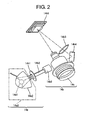
- FIG. 2 is an arrangement drawing of an example of the optical system 14 of the present embodiment.
- the optical system 14 is made up of a lamp module 14a emitting light from a light source and an engine module 14b to cast light from the lamp module 14a along a predetermined optical axis to the outside.
- the lamp module 14a is made up of a lamp 14a1 as the light source, a lamp reflector 14a2 for focusing light from the lamp 14a1 along a predetermined direction, and a lamp case 15 for accommodating therein the lamp 14a1 and lamp reflector 14a2.
- the engine module 14b is made up of a color wheel 14b1 for generating the three primary colors of R, G, and B from light emitted from the lamp module 14a, a light pipe 14b2 allowing the beams of light generated by the color wheel 14b1 to go straight, a mirror 14b4 for reflecting beams of light emitted from the light pipe 14b2, an illumination lens 14b3 for processing the beams of light into a predetermined shape, and a DMD 14b5 for reflecting incident beams of light thereon into a predetermined direction so as to be thrown on the projecting lens 14c.
- the dotted line indicates a trajectory of the optical axis in the optical system 14. Beams of light emitted from the lamp 14a1 as the light source are thrown on the DMD 14b5 with their optical axes kept constant.
- the arrowhead of the two-dot chain line indicates the traveling direction of light. While light emitted from the lamp 14a1 is separated by the color wheel 14b1 into light of each color of R, G, and B, the separated light beams are collected by the light pipe 14b2 and guided toward the mirror 14b4. The light beams output from the light pipe 14b2 are condensed by the illumination lens 14b3 located between the light pipe 14b2 and mirror 14b4 and rendered incident on the mirror 14b4 and, then, reflected by the mirror 14b4. The reflected light beams from the mirror 14b4 are condensed by the illumination lens 14b3 and rendered incident on the DMD 14b5.
- the DMD 14b5 Since the DMD 14b5 is of a known configuration, only a simple explanation will be given about the same here.
- the DMD 14b5 has a plurality of micro mirrors disposed on its reflecting face and generates an image by changing angles of the micro mirrors, thereby changing the positions of the reflected light beams. Therefore, deviation of the optical axis indicated by the dotted line in the drawing causes defects such as decrease in brightness of the image projected by the projecting lens 14c.
- FIG. 3 is a drawing showing the lamp module 14a of the present embodiment.
- the lamp case 15 is configured of a main body 15a provided with an opening for receiving the lamp reflector 14a2 therethrough, a light emitting window 15b1 through which light reflected from the lamp reflector 14a2-received into the main body 15a through the opening-is emitted, and a positioning portion 15b for proper positioning when a lid is applied to the opening of the main body 15a to enclose the lamp reflector 14a2 therein.
- the form of the lamp case 15 is not limited to such a one but any type of lamp case may be used if it can be fixed in the enclosure 16.
- the positioning portion 15b of the lamp case 15 is provided with positioning pins 15b2, 15b3 and a boss 15b4 for a screw to be used, as described later, when the lamp case 15 is fixed in the enclosure 16.
- the positioning pins 15b2, 15b3 are embedded in the side face of the positioning portion 15b, in a vertical direction thereto.
- the boss 15b4 has a hole allowing a screw to be passed therethrough substantially in parallel to the extended direction of the positioning pins 15b2, 15b3.
- the positioning portion 15b of the lamp case is made of forged magnesium. Further, the positioning pins are formed integral with the positioning portion 15b to ensure precision.
- the structure of the positioning portion 15b need not necessarily be such that is described above but one made of a material and configured so as to meet precision requirements of the lamp case 15 may be used.
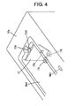
- FIG. 4 is a view of the enclosure 16 seen from the bottom.
- a lamp case fixing portion 17 for transmitting light from the lamp module 14a to the engine module 14b through an optical path 17a. More specifically, the lamp case fixing portion 17 mounts thereon the engine module 14b and the optical path 17a allows light from the lamp module 14a transmitted to the engine module 14b.
- the lamp case fixing portion 17 toward the bottom of the drawing, there are provided positioning holes 17b, 17c which allow the positioning pins 15b2, 15b3 of the lamp case 15 to be inserted therein.
- a socket portion 17d In the lamp case fixing portion 17, toward the top of the drawing, there is provided a socket portion 17d; the socket portion 17d is adapted to receive the head of the boss 15b4 and provided with a female screw engaging a screw passed through the boss 15b4.
- the receiving face 17d1 of the socket portion 17d is formed into a cone concave shape, and this shape allows the head of the boss 15b4 to be put in.
- the lamp case fixing portion 17 of the present embodiment is made of magnesium the same as positioning portion 15b of the lamp case 15 so as to ensure positioning precision.
- first rib 16b1 protruded a predetermined length.
- a concrete shape of the first rib 16b1 being described later, the first rib 16bl and the bottom face 16a are formed integral with each other in the present embodiment.
- the projector 10 has a lid 18 for covering up the opening of the lamp module receiving portion 16a1 after the lamp module 14a has been received into the lamp module receiving portion 16al.
- FIG. 5 is a drawing showing the shape of the lid. Referring to FIG. 5, the lid 18 is configured of a base portion 18a for covering up the opening of the lamp module receiving portion 16a1 and second ribs 18b1, 18b2, 18b3 erected substantially upright from the base portion 18a. The three second ribs 18b1, 18b2, 18b3 are arranged substantially triangularly and radially from the base portion 18a.
- the heights of the second ribs 18b1, 18b2, and 18b3 from the base portion 18a are made substantially equal to each other and they are integrally joined to the base portion 18a with a resin.
- Each of the second ribs 18b1, 18b2, and 18b3 has substantially a U-shaped cross-section. Therefore, in a state where the lamp module 14a is supported by the second ribs 18b1, 18b2, 18b3, vibrations transmitted from the lamp module 14a can be absorbed by the U-shaped cross-sections. Further, since the second ribs 18b1, 18b2, 18b3 are U-shaped and hence hollow-centered, shrinkage at the time of shaping the lid can be prevented and therefore the lid can be made to look nice.
- FIG. 6 is a drawing showing a lamp module to be fixed in an enclosure.
- the bottom face 16a of the enclosure 16 is first turned upward such that the opening of the lamp module receiving portion 16a1 looks upward. Then, the lamp module 14a is brought into the lamp module receiving portion 16a1.
- the positioning pins 15b2, 15b3 formed at the positioning portion 15b of the lamp case 15 are inserted into the positioning holes 17b, 17c of the lamp case fixing portion 17 within the lamp module receiving portion 16a1 and, at the same time, the boss 15b4 of the positioning portion 15b is inserted into the receiving face 17d1 of the socket portion 17d of the lamp case fixing portion 17. In this state, the boss 15b4 and socket portion 17d are fixed together by the screw 19.
- the enclosure 16 and the lid 18 are fixed together with screws.
- the lamp module 14a is controlled in its movement in a horizontal plane by the two positioning pins 15b2, 15b3 and the screw 19 and, at the same time, the lamp module 14a is vertically supported between the first rib 16bl disposed on the back side of the ceiling face 16b of the enclosure 16 and the three second ribs 18b1, 18b2, 18b3 disposed on the lid 18 to be secured in place.
- the lamp module 14a can be fixed in the enclosure 16 by a simple structure using only one screw. Furthermore, even if the projector is subjected to a shock, the optical axis is prevented from easily deviating by the shock absorbing effect of the two positioning pins 15b2, 15b3, the screw 19, and the ribs.
- FIG. 7 is an enlarged view of the lamp module 14a received in the enclosure 16. Referring to FIG. 7, while the lamp module 14a is fixed in the enclosure 16 by being supported vertically, there is formed a small gap between the first rib 16b1 and the lamp case 15 of the lamp module 14a.
- the gap between the lamp case 15 and the first rib 16b1 is set to be approximately 0.5mm.
- the lamp module is provided with two positioning pins to be inserted into positioning holes made in the enclosure in its vertical direction thereby controlling movement of the lamp module in a horizontal plane and the enclosure is provided with a first rib extended inward from the inner wall of the ceiling face and second ribs extended inward from the inner wall of the bottom face.
Landscapes
- Physics & Mathematics (AREA)
- General Physics & Mathematics (AREA)
- Projection Apparatus (AREA)
- Non-Portable Lighting Devices Or Systems Thereof (AREA)
Abstract
Description
- The present invention relates to a projector.
- FIG. 8 is a block diagram of a conventional projector. In FIG. 8, a
projector 1 is configured of alamp module 3 having received therein a lamp 3a as a light source disposed toward the front face side of anenclosure 2, anengine module 4 generating an image on the basis of light from the lamp, and a projecting lens 5 for projecting the image generated by theengine module 4. Light emitted from the lamp 3a as the light source is passed through theengine module 4 and a DMD 4a to be finally projected from the projecting lens 5. Therefore, thelamp module 3 for fixing the lamp 3a to theenclosure 2 is required to be securely fixed to theenclosure 2 so that the optical axis of light emitted from the light source may not deviate from the right path. - As a conventional method to fix a
lamp module 3 to anenclosure 2 so that the optical axis may not deviate, there is known a technology to fixedly position thelamp module 3 in a horizontal direction and vertical direction with the use of a plurality of screws. In the fixation of thelamp module 3 with the use of a plurality of screws, it is naturally required that high positioning accuracy of thelamp module 3 is secured by each screw. Further, in the positioning of thelamp module 3, the datums would not easily match because of tolerances of the screws relative to their respective female screws and therefore the assembling work has taken a lot of trouble. - As a conventional method for fixing a lamp module to an enclosure such that the optical axis dose not deviate from a right path, there is known one having positioning planes arranged to support therebetween the upper and lower faces of the lamp module, a convexity formed on a face opposite to the light emitting face of the lamp module, and a coil spring to abut on the convexity when the lamp module is received into the enclosure. In this configuration, after the lamp module has been controlled in its vertical movement by the positioning faces, it is retained in place with the coil spring abutting on the convexity (refer to JU-3092161).
- Also, to simplify the work of fixing and removing a lamp module to and from an enclosure with use of fixing screws, there is disclosed a method, which does not use tools but has ribs, coming into engagement with the fixing screws, formed on a lid, so that the fixing screws may be tightened or loosened by the ribs on the lid (refer to
JP-A-2004-347789 - Further, there is disclosed a method to fix a lamp module to an enclosure by forming bosses on the lamp module and forming, opposite thereto, a slip preventing member on the side of the enclosure (refer to
JP-A-2005-43603 - In the invention of the above mentioned
patent document 1, since the positioning faces are provided by the inner wall of the enclosure and the lamp module is only supported therebetween, there has been a problem that the optical axis of the lamp module is easily deviated by a shock when for example the projector is dropped. - The invention disclosed in the
patent document 2 is just for facilitating removal of the lamp module from the enclosure and therefore the deviation of the optical axis of light emitted from the lamp module cannot be prevented. - Further, in the case of the
patent document 3, it was required to provide slip preventing members in the enclosure, and therefore, the shape of the enclosure receiving the lamp module therein naturally became complicated to take unnecessary cost for manufacturing the enclosure. - It is aimed to provide, by a simple structure, a projector in which the lamp module and enclosure are securely fixed together so that the optical axis may not deviate and also the optical axis is prevented from deviating even if the projector is subjected to a shock.
- In a first aspect of the present invention, while positioning pins are inserted into positioning holes in a fixing portion to perform positioning, a screw passed through a boss is engaged with a female screw in a socket portion, and thus, a lamp module, with its movement in a horizontal plane controlled, is received into a lamp module receiving portion. Then, by fastening a lid with screws to cover up an opening of the lamp module receiving portion, the lamp module is controlled in its vertical movement by a first rib formed on the bottom face of the lamp module receiving portion and second ribs formed on the lid. In this way, the lamp module is controlled in its movement in the horizontal direction and vertical direction and an optical axis of light emitted from the lamp module is fixed.
- In another aspect of the present invention, a lamp module is controlled in its movement in a horizontal plane by having positioning pins inserted into positioning holes provided in a vertical direction in an enclosure and further the lamp module is received into the enclosure as supported vertically between a first rib and second ribs formed on the ceiling face and the bottom face of the enclosure, and therefore, the configuration can fix the lamp module within the enclosure by a simple structure and, even if it is subjected to a shock, it prevents the optical axis from deviating easily by virtue of the positioning pins and screw. Thus, it is made possible to fix the lamp module and the enclosure together, by a simple structure, so as not to cause a deviation of the optical axis, and also to provide a projector in which the optical axis can be prevented from easily deviating even if it is subjected to a shock.
- As an example of the configuration of the second ribs, the second ribs are formed on the lid member serving as the bottom face. Therefore, when the second ribs are formed, they can be formed separate from the main body side of the enclosure. Thus, manufacturing of the enclosure having the first rib and the second ribs thereon can be made easier.
- As a concrete example of the shape of the second ribs, each of the second ribs is formed to have a U-shaped cross-section. Accordingly, when subjected to a shock, the impulse can be absorbed by the U-shaped cross-section and, further, the shape of the bottom plate of the enclosure is prevented from producing deformation due to shrinkage during the manufacture of the second ribs.
- As a concrete example of the shape of the first rib, a small gap is formed between the lamp module and the first rib, and therefore, when the lamp module is assembled into the enclosure, a deviation of the optical axis due to interference between the first rib and the lamp module can be prevented.
-
- FIG. 1 is a diagram showing a block configuration of a projector;
- FIG. 2 is a drawing showing an optical system;
- FIG. 3 is a drawing showing a lamp module;
- FIG. 4 is a bottom view of an enclosure;
- FIG. 5 is a drawing showing the shape of a lid member;
- FIG. 6 is drawing showing a lamp module fixed in an enclosure;
- FIG. 7 is an enlarged view of a lamp module received in an enclosure; and
- FIG. 8 is a block diagram of a conventional projector.
- A projector as an embodiment of the present invention will be described in the following order:
- A. Configuration of the projector;
- B. Method of fixation of the lamp module;
- C. Example of variation; and
- D. Summary.
- Referring to FIG. 1 - FIG. 8, an embodiment in which a projector according to the present invention is realized will be described. FIG. 1 is a block configuration diagram of the
projector 10 according to the present invention. Referring to the diagram, theprojector 10 has abox type enclosure 16. Theenclosure 16 accommodates an optical system 14 for projecting an image by the use of light from a lamp, adigital board 11 for controlling the optical system 14, a power supply board 13 for providing thedigital board 11 with necessary power supply, and an input-output board 12 for receiving a video signal and an audio signal from external equipment such as a personal computer and also accepting an operating signal transmitted from aremote controller 10a. Explanation of each component and explanation of functioning of theprojector 10 will be given below. - The input-
output board 12 mounts thereon an input-output terminal 12b and aninfrared receiver converter 12a and it outputs signals from the input-output terminal 12b andinfrared receiver converter 12a to thedigital board 11. The input-output terminal 12b includes a video terminal and an audio terminal for receiving a video signal and an audio signal from external equipment such as a personal computer and it outputs the video signal and audio signal received through the video terminal and audio terminal to thedigital board 11. Theinfrared receiver converter 12a receives an infrared operating signal transmitted from theremote controller 10a and, converting the received infrared signal into an operating signal having a predetermined voltage value, outputs the converted operating signal to thedigital board 11. The output signals from the input-output terminal 12b andinfrared receiver converter 12a are output to thedigital board 11 through signal lines. - The digital board 7.7. has, mounted on one side thereof, 1C devices and the like constituting a microcomputer 11a, a
recording module 11b, avideo signal processor 11d, and an OSD (on screen display)circuit 11c. Within thedigital board 11, the microcomputer 11a is connected through buses with therecording module 11b, thevideo signal processor 11d, and theOSD circuit 11c. The microcomputer 11a accepts an operating signal from theinfrared receiver converter 12a and issues, based on predetermined programs recorded on the recording modulellb, predetermined commands to the video signal processor lid andOSD circuit 11c and also performs control all the circuits. - The video signal processor lid separates the video signal input from the input-
output terminal 12b through the signal line into RGB signal containing the three primary colors of red R, green G, and blue B, and thereafter, performs correction of the RGB signal for the color level or the like based on a control signal from the microcomputer 11a and outputs the corrected RGB signal to the optical system 14. TheOSD circuit 11c, connected with thevideo signal processor 11d, generates an OSD signal representing the image to be OSD-displayed on the screen and superposes the generated signal on the video signal. Thedigital board 11, under the control of the microcomputer 11a, accepts the operating signal from theinfrared receiver converter 12a and generates an OSD signal corresponding to the accepted operating signal. - The power supply board 13 rectifies an external power supply (for example, 100V commercial AC source), supplied from a
wall socket 13a, by a rectifier composed of thyristors and, thereafter, generates again an AC power supply needed for operating theprojector 10 and provides the power supply to thedigital board 11 and optical system 14. - The optical system 14 generates RGB light based on the video signal generated by the
video signal processor 11d, under the control of the microcomputer 11a, and project the generated light onto a screen or the like through a projecting lens. FIG. 2 is an arrangement drawing of an example of the optical system 14 of the present embodiment. In FIG. 2, the optical system 14 is made up of a lamp module 14a emitting light from a light source and anengine module 14b to cast light from the lamp module 14a along a predetermined optical axis to the outside. The lamp module 14a is made up of a lamp 14a1 as the light source, a lamp reflector 14a2 for focusing light from the lamp 14a1 along a predetermined direction, and alamp case 15 for accommodating therein the lamp 14a1 and lamp reflector 14a2. - The
engine module 14b is made up of a color wheel 14b1 for generating the three primary colors of R, G, and B from light emitted from the lamp module 14a, a light pipe 14b2 allowing the beams of light generated by the color wheel 14b1 to go straight, a mirror 14b4 for reflecting beams of light emitted from the light pipe 14b2, an illumination lens 14b3 for processing the beams of light into a predetermined shape, and a DMD 14b5 for reflecting incident beams of light thereon into a predetermined direction so as to be thrown on the projectinglens 14c. In FIG. 2, the dotted line indicates a trajectory of the optical axis in the optical system 14. Beams of light emitted from the lamp 14a1 as the light source are thrown on the DMD 14b5 with their optical axes kept constant. - In FIG. 2, the arrowhead of the two-dot chain line indicates the traveling direction of light. While light emitted from the lamp 14a1 is separated by the color wheel 14b1 into light of each color of R, G, and B, the separated light beams are collected by the light pipe 14b2 and guided toward the mirror 14b4. The light beams output from the light pipe 14b2 are condensed by the illumination lens 14b3 located between the light pipe 14b2 and mirror 14b4 and rendered incident on the mirror 14b4 and, then, reflected by the mirror 14b4. The reflected light beams from the mirror 14b4 are condensed by the illumination lens 14b3 and rendered incident on the DMD 14b5. Since the DMD 14b5 is of a known configuration, only a simple explanation will be given about the same here. The DMD 14b5 has a plurality of micro mirrors disposed on its reflecting face and generates an image by changing angles of the micro mirrors, thereby changing the positions of the reflected light beams. Therefore, deviation of the optical axis indicated by the dotted line in the drawing causes defects such as decrease in brightness of the image projected by the projecting
lens 14c. - FIG. 3 is a drawing showing the lamp module 14a of the present embodiment. In this drawing, the
lamp case 15 is configured of amain body 15a provided with an opening for receiving the lamp reflector 14a2 therethrough, a light emitting window 15b1 through which light reflected from the lamp reflector 14a2-received into themain body 15a through the opening-is emitted, and apositioning portion 15b for proper positioning when a lid is applied to the opening of themain body 15a to enclose the lamp reflector 14a2 therein. Although a closed type oflamp case 15 having the lamp 14al and lamp reflector 14a2 enclosed therein is used as the lamp module 14a in the present embodiment, the form of thelamp case 15 is not limited to such a one but any type of lamp case may be used if it can be fixed in theenclosure 16. - The
positioning portion 15b of thelamp case 15 is provided with positioning pins 15b2, 15b3 and a boss 15b4 for a screw to be used, as described later, when thelamp case 15 is fixed in theenclosure 16. The positioning pins 15b2, 15b3 are embedded in the side face of thepositioning portion 15b, in a vertical direction thereto. The boss 15b4 has a hole allowing a screw to be passed therethrough substantially in parallel to the extended direction of the positioning pins 15b2, 15b3. Thepositioning portion 15b of the lamp case is made of forged magnesium. Further, the positioning pins are formed integral with thepositioning portion 15b to ensure precision. However, the structure of thepositioning portion 15b need not necessarily be such that is described above but one made of a material and configured so as to meet precision requirements of thelamp case 15 may be used. - The
enclosure 16 is provided with an opening therein and thelamp case 15 is received on the bottom face thereof by having the opening covered with a lid. FIG. 4 is a view of theenclosure 16 seen from the bottom. Referring to FIG. 4, within a lamp module receiving portion 16a1 provided in thebottom face 16a, there is fixedly disposed a lampcase fixing portion 17 for transmitting light from the lamp module 14a to theengine module 14b through anoptical path 17a. More specifically, the lampcase fixing portion 17 mounts thereon theengine module 14b and theoptical path 17a allows light from the lamp module 14a transmitted to theengine module 14b. - In the lamp
case fixing portion 17, toward the bottom of the drawing, there are providedpositioning holes lamp case 15 to be inserted therein. In the lampcase fixing portion 17, toward the top of the drawing, there is provided asocket portion 17d; thesocket portion 17d is adapted to receive the head of the boss 15b4 and provided with a female screw engaging a screw passed through the boss 15b4. The receiving face 17d1 of thesocket portion 17d is formed into a cone concave shape, and this shape allows the head of the boss 15b4 to be put in. Thus, with the positioning pins 15b2, 15b3 of thelamp case 15 inserted into thepositioning holes case fixing portion 17 of the present embodiment is made of magnesium the same as positioningportion 15b of thelamp case 15 so as to ensure positioning precision. - On the bottom face of the lamp module receiving portion 16a1, namely on the back side of the ceiling face thereof, there is provided a first rib 16b1 protruded a predetermined length. A concrete shape of the first rib 16b1 being described later, the first rib 16bl and the
bottom face 16a are formed integral with each other in the present embodiment. - The
projector 10 has alid 18 for covering up the opening of the lamp module receiving portion 16a1 after the lamp module 14a has been received into the lamp module receiving portion 16al. FIG. 5 is a drawing showing the shape of the lid. Referring to FIG. 5, thelid 18 is configured of abase portion 18a for covering up the opening of the lamp module receiving portion 16a1 and second ribs 18b1, 18b2, 18b3 erected substantially upright from thebase portion 18a. The three second ribs 18b1, 18b2, 18b3 are arranged substantially triangularly and radially from thebase portion 18a. The heights of the second ribs 18b1, 18b2, and 18b3 from thebase portion 18a are made substantially equal to each other and they are integrally joined to thebase portion 18a with a resin. Thus, when the opening of the lamp module receiving portion 16a1 is covered with thelid 18, the second ribs 18b1, 18b2, 18b3 come to positions opposite to the lamp module 14a. - Each of the second ribs 18b1, 18b2, and 18b3 has substantially a U-shaped cross-section. Therefore, in a state where the lamp module 14a is supported by the second ribs 18b1, 18b2, 18b3, vibrations transmitted from the lamp module 14a can be absorbed by the U-shaped cross-sections. Further, since the second ribs 18b1, 18b2, 18b3 are U-shaped and hence hollow-centered, shrinkage at the time of shaping the lid can be prevented and therefore the lid can be made to look nice.
- A method for fixing the lamp module 14a in place by the use of the
enclosure 16 and thelid 18 will be described. FIG. 6 is a drawing showing a lamp module to be fixed in an enclosure. Referring to FIG. 6, in order to fix the lamp module 14a, thebottom face 16a of theenclosure 16 is first turned upward such that the opening of the lamp module receiving portion 16a1 looks upward. Then, the lamp module 14a is brought into the lamp module receiving portion 16a1. At this time, the positioning pins 15b2, 15b3 formed at thepositioning portion 15b of thelamp case 15 are inserted into thepositioning holes case fixing portion 17 within the lamp module receiving portion 16a1 and, at the same time, the boss 15b4 of thepositioning portion 15b is inserted into the receiving face 17d1 of thesocket portion 17d of the lampcase fixing portion 17. In this state, the boss 15b4 andsocket portion 17d are fixed together by thescrew 19. - Finally, with the opening of the lamp module receiving portion 16a1 covered with the
lid 18, theenclosure 16 and thelid 18 are fixed together with screws. At this time, the lamp module 14a is controlled in its movement in a horizontal plane by the two positioning pins 15b2, 15b3 and thescrew 19 and, at the same time, the lamp module 14a is vertically supported between the first rib 16bl disposed on the back side of theceiling face 16b of theenclosure 16 and the three second ribs 18b1, 18b2, 18b3 disposed on thelid 18 to be secured in place. With the above described configuration, the lamp module 14a can be fixed in theenclosure 16 by a simple structure using only one screw. Furthermore, even if the projector is subjected to a shock, the optical axis is prevented from easily deviating by the shock absorbing effect of the two positioning pins 15b2, 15b3, thescrew 19, and the ribs. - In the configuration described above, the lamp module 14a is arranged to be supported between the first rib 16b1 and the second ribs 18b1, 18b2, 18b3. However, it becomes easier to assemble the lamp module 14a into the enclosure by modifying the shape of the first rib 16bl. FIG. 7 is an enlarged view of the lamp module 14a received in the
enclosure 16. Referring to FIG. 7, while the lamp module 14a is fixed in theenclosure 16 by being supported vertically, there is formed a small gap between the first rib 16b1 and thelamp case 15 of the lamp module 14a. - In the present embodiment, the gap between the
lamp case 15 and the first rib 16b1 is set to be approximately 0.5mm. By this design, such a failure can be prevented that the lamp module 14a is fixed in place with its optical axis deviated from the correct path because of the first rib 16b1 and the outer face of thelamp case 15 interfering each other, when the lamp module 14a is fixed by means of the positioning pins 15b2, 15b3 and thescrew 19, making it impossible for the positioning pins 15b2, 15b3 to be positively inserted. - In order to provide a projector having the lamp module and the enclosure fixed together by a simple structure in such a way that the optical axis does not deviate from the right path and even if the projector is subjected to a shock the optical axis is prevented from being easily deviated, the lamp module is provided with two positioning pins to be inserted into positioning holes made in the enclosure in its vertical direction thereby controlling movement of the lamp module in a horizontal plane and the enclosure is provided with a first rib extended inward from the inner wall of the ceiling face and second ribs extended inward from the inner wall of the bottom face. Thus, the lamp module is properly positioned in a horizontal direction by the positioning pins, and following fixation with one screw, the lamp module is vertically supported between the first rib and the second ribs so as to be received in the enclosure with the optical axis fixed.
Claims (5)
- A projector comprising:a lamp module for receiving therein a lamp as a light source; andan enclosure for allowing an optical axis of a light source from said lamp module to be fixedly aligned to a predetermined direction by covering, with a lid, an opening of a lamp module receiving portion for receiving therein said lamp module;said lamp module having, for controlling movement of said optical axis in a horizontal plane, two positioning pins embedded therein in a substantially vertical direction to said optical axis and a boss allowing a screw to pass therethrough in parallel with a direction said positioning pins are embedded;said enclosure having a first rib extended inward from a back side of a ceiling face, or a bottom face of said lamp module receiving portion and three second ribs, each thereof having a substantially U-shaped cross-section, embedded upright from said lid in a triangularly arrangement such that when said lamp module is received in said lamp module receiving portion, a small gap is formed between said enclosure and said lamp module; andsaid lamp module receiving portion having a positioning portion including positioning holes allowing the two positioning pins to be inserted therein and a socket portion provided with a female screw engaging the screw passed through said boss,whereinwhile being properly positioned by said positioning pins inserted into the positioning holes of said positioning portion, said lamp module is received into said lamp module receiving portion with its movement in a horizontal plane controlled by the screw passed through said boss and engaged with the female screw in the socket portion, and said opening in said lamp module receiving portion is covered with the lid fastened with screws such that movement of said lamp module in a vertical direction is controlled by said first rib and said second ribs in order for the optical axis to be fixed.
- A projector comprising:a lamp module for receiving therein a lamp as a light source;an enclosure fixing said lamp module therein such that an optical axis of said lamp module is kept in a predetermined direction;two positioning pins provided on said lamp module and adapted to be inserted into positioning holes made in a vertical direction to said enclosure for controlling movement of said lamp module in a horizontal plane; anda first rib provided on said enclosure as extended inward from an inner wall of a ceiling plate and second ribs provided on said enclosure as extended inward from an inner wall of a bottom plate,whereinsaid lamp module is fixed in said enclosure by being secured by one screw while said lamp module is positioned within a horizontal plane by said positioning pins, and further by being vertically supported between said first rib and second ribs.
- The projector as set forth in claim 2 wherein:said enclosure receives the lamp module into a lamp module receiving portion having an opening made in its bottom face and secures the lamp module therein by having the opening covered with a lid, andsaid second ribs are formed on a face of said lid opposing said lamp module.
- The projector as set forth in claim 2 or claim 3 wherein:said second ribs each have a U-shaped cross-section.
- The projector as set forth in claim 2, claim 3 or claim 4 wherein:when said lamp module is fixed in said enclosure, said first rib is extended such that a small gap is formed between the same and said lamp module.
Applications Claiming Priority (1)
| Application Number | Priority Date | Filing Date | Title |
|---|---|---|---|
| JP2006145540A JP2007316312A (en) | 2006-05-25 | 2006-05-25 | Projector |
Publications (2)
| Publication Number | Publication Date |
|---|---|
| EP1860497A2 true EP1860497A2 (en) | 2007-11-28 |
| EP1860497A3 EP1860497A3 (en) | 2009-03-18 |
Family
ID=38310097
Family Applications (1)
| Application Number | Title | Priority Date | Filing Date |
|---|---|---|---|
| EP07010164A Withdrawn EP1860497A3 (en) | 2006-05-25 | 2007-05-22 | Projector and lamp module |
Country Status (3)
| Country | Link |
|---|---|
| US (1) | US7476009B2 (en) |
| EP (1) | EP1860497A3 (en) |
| JP (1) | JP2007316312A (en) |
Families Citing this family (2)
| Publication number | Priority date | Publication date | Assignee | Title |
|---|---|---|---|---|
| JP6052582B2 (en) * | 2012-08-09 | 2016-12-27 | 株式会社リコー | Image projection device |
| CN105301875B (en) * | 2014-07-30 | 2017-03-29 | 中强光电股份有限公司 | Projector lamp module and lamp module fixing method |
Citations (2)
| Publication number | Priority date | Publication date | Assignee | Title |
|---|---|---|---|---|
| JP2004347789A (en) | 2003-05-21 | 2004-12-09 | Funai Electric Co Ltd | Image display projector |
| JP2005043603A (en) | 2003-07-28 | 2005-02-17 | Funai Electric Co Ltd | Projector |
Family Cites Families (6)
| Publication number | Priority date | Publication date | Assignee | Title |
|---|---|---|---|---|
| JPH0392161U (en) * | 1989-12-30 | 1991-09-19 | ||
| US5267128A (en) * | 1992-10-26 | 1993-11-30 | Chrysler Corporation | Facia mounted for lamp assembly |
| US6467911B1 (en) * | 1998-10-08 | 2002-10-22 | Minolta Co., Ltd. | Projector and lamp unit |
| JP3572982B2 (en) * | 1999-02-19 | 2004-10-06 | セイコーエプソン株式会社 | Projection display device |
| US6398366B1 (en) * | 1999-10-15 | 2002-06-04 | Sony Corporation | Image display apparatus of the projection type |
| TW484032B (en) * | 2000-07-25 | 2002-04-21 | Coretronic Corp | Projector having easily assembled lamp module and method of assembly thereof |
-
2006
- 2006-05-25 JP JP2006145540A patent/JP2007316312A/en active Pending
-
2007
- 2007-05-22 EP EP07010164A patent/EP1860497A3/en not_active Withdrawn
- 2007-05-23 US US11/805,340 patent/US7476009B2/en not_active Expired - Fee Related
Patent Citations (2)
| Publication number | Priority date | Publication date | Assignee | Title |
|---|---|---|---|---|
| JP2004347789A (en) | 2003-05-21 | 2004-12-09 | Funai Electric Co Ltd | Image display projector |
| JP2005043603A (en) | 2003-07-28 | 2005-02-17 | Funai Electric Co Ltd | Projector |
Also Published As
| Publication number | Publication date |
|---|---|
| EP1860497A3 (en) | 2009-03-18 |
| JP2007316312A (en) | 2007-12-06 |
| US20070274076A1 (en) | 2007-11-29 |
| US7476009B2 (en) | 2009-01-13 |
Similar Documents
| Publication | Publication Date | Title |
|---|---|---|
| USRE43959E1 (en) | Multi-lamp arrangement for optical systems | |
| JP4428434B2 (en) | Optical device and projector | |
| US8070300B2 (en) | Projection display with a detachable lamp | |
| JP2019002969A (en) | Projection optical device and projector | |
| US8985786B2 (en) | Image projection apparatus | |
| US6509938B2 (en) | Liquid crystal display video projector and method of repairing same | |
| US11531255B2 (en) | Projector, projection optical device, and method of controlling projector | |
| US7476009B2 (en) | Projector | |
| JP6283993B2 (en) | Projection optical device and image projection device | |
| CN113075843B (en) | Projection optical machine and projector | |
| US6869186B2 (en) | Optical device and projector | |
| CN214670028U (en) | Projection optical machine and projector | |
| JP2012008183A (en) | Projector | |
| JP6860701B2 (en) | Projection type image display device | |
| JP2006126436A (en) | Rear projection type imaging apparatus | |
| JP3603647B2 (en) | Projection display device | |
| US12019357B2 (en) | Projector device with imaging lens | |
| JP6551567B2 (en) | projector | |
| JP2001021987A (en) | Projection display device | |
| JP4375350B2 (en) | projector | |
| JP2009171179A (en) | Electronics | |
| CN114594648A (en) | Projection device and extension unit of projection device | |
| EP1359447A2 (en) | A multi-lamp arrangement for optical systems | |
| JP2017173572A (en) | projector | |
| JP2007003633A (en) | Projector unit and projection television apparatus |
Legal Events
| Date | Code | Title | Description |
|---|---|---|---|
| PUAI | Public reference made under article 153(3) epc to a published international application that has entered the european phase |
Free format text: ORIGINAL CODE: 0009012 |
|
| AK | Designated contracting states |
Kind code of ref document: A2 Designated state(s): AT BE BG CH CY CZ DE DK EE ES FI FR GB GR HU IE IS IT LI LT LU LV MC MT NL PL PT RO SE SI SK TR |
|
| AX | Request for extension of the european patent |
Extension state: AL BA HR MK YU |
|
| PUAL | Search report despatched |
Free format text: ORIGINAL CODE: 0009013 |
|
| AK | Designated contracting states |
Kind code of ref document: A3 Designated state(s): AT BE BG CH CY CZ DE DK EE ES FI FR GB GR HU IE IS IT LI LT LU LV MC MT NL PL PT RO SE SI SK TR |
|
| AX | Request for extension of the european patent |
Extension state: AL BA HR MK RS |
|
| 17P | Request for examination filed |
Effective date: 20090724 |
|
| AKX | Designation fees paid |
Designated state(s): DE FR GB |
|
| 17Q | First examination report despatched |
Effective date: 20101029 |
|
| STAA | Information on the status of an ep patent application or granted ep patent |
Free format text: STATUS: THE APPLICATION IS DEEMED TO BE WITHDRAWN |
|
| 18D | Application deemed to be withdrawn |
Effective date: 20110309 |