EP1860495A2 - Video projector - Google Patents
Video projector Download PDFInfo
- Publication number
- EP1860495A2 EP1860495A2 EP07010272A EP07010272A EP1860495A2 EP 1860495 A2 EP1860495 A2 EP 1860495A2 EP 07010272 A EP07010272 A EP 07010272A EP 07010272 A EP07010272 A EP 07010272A EP 1860495 A2 EP1860495 A2 EP 1860495A2
- Authority
- EP
- European Patent Office
- Prior art keywords
- hole
- mounting base
- operation button
- video projector
- center
- Prior art date
- Legal status (The legal status is an assumption and is not a legal conclusion. Google has not performed a legal analysis and makes no representation as to the accuracy of the status listed.)
- Granted
Links
- 230000003287 optical effect Effects 0.000 claims description 19
- 238000009434 installation Methods 0.000 claims description 8
- 230000000007 visual effect Effects 0.000 description 7
- 238000001816 cooling Methods 0.000 description 6
- 239000000463 material Substances 0.000 description 6
- 230000004907 flux Effects 0.000 description 5
- 238000005192 partition Methods 0.000 description 3
- 239000003086 colorant Substances 0.000 description 2
- 239000000805 composite resin Substances 0.000 description 2
- 239000004973 liquid crystal related substance Substances 0.000 description 2
- 238000004519 manufacturing process Methods 0.000 description 2
- 239000007769 metal material Substances 0.000 description 2
- 239000011347 resin Substances 0.000 description 2
- 229920005989 resin Polymers 0.000 description 2
- 238000010521 absorption reaction Methods 0.000 description 1
- 229920000122 acrylonitrile butadiene styrene Polymers 0.000 description 1
- 239000011248 coating agent Substances 0.000 description 1
- 238000000576 coating method Methods 0.000 description 1
- 230000007423 decrease Effects 0.000 description 1
- 238000010586 diagram Methods 0.000 description 1
- 238000006073 displacement reaction Methods 0.000 description 1
- 238000000034 method Methods 0.000 description 1
- 238000012986 modification Methods 0.000 description 1
- 230000004048 modification Effects 0.000 description 1
- 230000000149 penetrating effect Effects 0.000 description 1
- 230000002194 synthesizing effect Effects 0.000 description 1
Images

Classifications
-
- G—PHYSICS
- G03—PHOTOGRAPHY; CINEMATOGRAPHY; ANALOGOUS TECHNIQUES USING WAVES OTHER THAN OPTICAL WAVES; ELECTROGRAPHY; HOLOGRAPHY
- G03B—APPARATUS OR ARRANGEMENTS FOR TAKING PHOTOGRAPHS OR FOR PROJECTING OR VIEWING THEM; APPARATUS OR ARRANGEMENTS EMPLOYING ANALOGOUS TECHNIQUES USING WAVES OTHER THAN OPTICAL WAVES; ACCESSORIES THEREFOR
- G03B21/00—Projectors or projection-type viewers; Accessories therefor
- G03B21/14—Details
- G03B21/145—Housing details, e.g. position adjustments thereof
Definitions
- the present invention relates to a video projector which projects images on an external screen, and especially relates to a video projector having angular adjustability to an installation surface.
- a video projector which projects images on an external screen on the basis of image signals outputted from a personal computer, for example, has an angle adjusting mechanism to adjust an angle of an optical axis of a projection lens with respect to an installation surface of the video projector so as to project the image on the screen properly.
- a conventional angle adjusting mechanism is comprised of a rod-shaped support adjustably provided at a front center of a housing of the video projector, for example, to protrude downward from the bottom of the housing and a locking mechanism to lock the movement of the support.
- the locking mechanism is further linked with a operation button via a link lever to release the locking of the support by the locking mechanism.
- the support is locked up by the locking mechanism when it protrudes downward from the bottom of the housing of the video projector, so that the support can hold an inclined posture of the video projector.
- the support and the locking mechanism has a plurality of hooking points corresponding to protruding height of the support from the bottom of the housing, and thus, the angle of the optical axis of the projection lens with respect to the installation surface can be adjusted.
- the operation button and the link lever are generally independently formed with different materials.
- the inside of the housing of the video projector becomes high temperature due to heat of a light source and so on, so that an element such as the link lever which is disposed in the vicinity of a heat source or required the rigidity is formed of a metal material or a composite resin material.
- the operation button which is partially exposed outside is formed of a generic resin material in consideration of a manufacturing cost or an appearance design.
- the link lever and the operation button were integrally formed, the shape of the integrated member might have become complex and the manufacturing cost thereof be increased.
- the operation button and the link lever which are independently formed, are coupled with a screw, for example, so that the link lever is moved in conjunction with the motion of the operation button. Since the link lever is a movable member, it is held on the housing with a predetermined allowance in consideration of the dimensional tolerance.
- the link lever when vibrations are applied to the video projector, or sounds are outputted at megavolume from a built-in speaker of the video projector, for example, the link lever is resonated in the allowance.
- the resonance of the link lever further causes frictional contact of the operation button and edge of a button hole of the housing into which the operation button is inserted, so that frictional sounds are generated due to the frictional contacts of the operation button and the edge of the button hole.
- frictional sounds are rudeness to the user.
- the size of the button hole must be selected a little larger that the size of the outer shape of the operation button in consideration of the dimensional tolerances of the housing, the link lever and the operation button manufactured, so that a clearance between the edges of the button hole and the operation button becomes wider, and thus, visual quality of the video projector is deteriorated. Furthermore, the user may feel the operationality of the operation button is not so good, because the allowance of the operation button to the housing may be felt larger.
- Japanese Laid-Open Patent Publication No. 2006-49068 discloses a push knob structure that prevents displacement of a support member and a base member. Although this structure shown in 2006-49068 can prevent the inclination of the push knob, it, however, cannot reduce the frictional sounds due to the frictional contacts of the operation button and the edge of the button hole of the housing, as described above. Furthermore, the visual quality of the video projector cannot be increased, even if the structure is applied to the operation button of the video projector.
- Japanese Laid-Open Patent Publication No. 2004-281291 discloses a structure that enables to protrude a operation surface of a push button from a button hole into which the push button is inserted and prevents backlash of a push button, even when a center of the push button is discrepant from a guide of a chassis due to location accuracy of the button hole on a front panel is lower.
- the structure shown in 2004-281291 cannot increase the visual quality of the apparatus, and the mechanism of the push button becomes complex.
- the present invention is perceived to solve the problem described above, and an object of the present invention is to provide a video projector having an angle adjusting mechanism with an operation button, in which a clearance between edges of the operation button and a button hole of a housing into which the operation button is inserted can be made smaller, frictional sounds due to frictional contacts of the operation button and the edge of the button hole can be reduced, a visual quality of the video projector can be increased, and operationality to operate the operation button can be improved.
- a video projector in accordance with an aspect of the present invention comprises: a light source; an image forming unit that forms an image with using image data; a projection lens that projects the image formed by the image forming unit to a screen disposed in front of the video projector; an angle adjusting mechanism that adjusts an angle of an optical axis of the projection lens with respect to an installation surface on which the video projector is installed; and a housing that contains the light source, the image forming unit, the projection lens and the angle adjusting mechanism.
- the housing is comprised of an upper housing member having a button hole formed on a face thereof, and a lower housing member on which the light source, the image forming unit, the projection lens and the angle adjusting mechanism are mounted.
- the angle adjusting mechanism is further comprised of a support which can be pulled out downward from a bottom of the lower housing member to protrude a desired height, a lock member to lock movement of the support, a link lever to release locking of the support by the lock member when it is moved, and an operation button having a top end portion inserted into the button hole of the upper housing member and movably held on the link lever in a direction substantially parallel to the face on which the button hole is formed.
- the operation button is movable held on the link lever in a direction substantially parallel to the face on which the button hole is formed, for example, a top face of the housing, the position of the top end portion of the operation button can be displaced to be adjusted to the position of the button hole, even though the dimensional tolerances of the elements are larger.
- the top end portion of the operation button can be inserted into the button hole even when the clearance between the edges of the operation button and the button hole is smaller.
- a clearance between edges of the operation button and a button hole of a housing into which the operation button is inserted can be made smaller, frictional sounds due to frictional contacts of the operation button and the edge of the button hole can be reduced, a visual quality of the video projector can be increased, and operationality to operate the operation button can be improved.
- the link lever has a mounting base on which the operation button is movably held at an end thereof;
- the mounting base is a flat plate having at least one hole; and
- the operation member has at least one protrusion on a rear face, which has a diameter smaller than the hole and penetrates through the hole.
- the hole of the mounting base is a through hole; and the protrusion of the operation member has a screw hole, and a screw having a flange diameter is larger than a diameter of the hole of the mounting base is screwed to the screw hole intervening the mounting base enabling the operation member movably held on the mounting base of the link lever.
- the mounting base has a center through hole formed at a center thereof and a pair of side trough holes formed at both sides of the center through hole in a widthwise direction of the video projector;
- the operation button has a center post with a screw hole formed at a center on a rear face of the operation button, and a pair of protrusions having a diameter smaller than that of the center post; a diameter of the center through hole is larger than an outer diameter of the center post, and a diameter of the side through holes is larger than an outer diameter of the protrusions; rear face of the top end portion of the operation button is concaved, and ribs are formed to join the center post and the protrusions so as to increase the mechanical strengths of the center post and the protrusions; the center post penetrates the center through hole, the protrusions penetrate the side through holes of the mounting base, and a screw is screwed into the screw hole of the center post intervening the mounting base; and heights of the center post and the protrusion
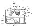
- FIG. 1 shows a video projector 1 in accordance with the present invention.
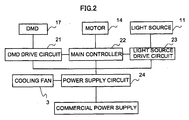
- FIG 2 shows a circuit configuration of the video projector 1.
- FIG. 3 is a sight through perspective view showing a configuration of the video projector 1.
- the video projector 1 is used to project an enlarged image on a screen which is located in front of the video projector 1 by using image signals (image data) outputted from a personal computer, a video camera, or the like.
- the video projector 1 comprises an optical engine 10 that is located on a front side of a housing 2, forms an image by using image signals inputted from outside, and enlarges and projects the image on a screen located in front of the video projector 1, and a controller 20 that is located on a rear side of the housing 2, processes the image signals inputted from outside, and controls the optical engine 10.
- An angle adjusting mechanism 30, which varies an angle of the housing 2 with respect to an installation surface, that is, the posture of the video projector 1, is provided at a front center portion of the housing 2.
- the housing 2 is comprised of an upper housing member 2a and a lower housing member 2b.
- the optical engine 10, the controller 20 and the angle adjusting mechanism 30 are initially mounted on the lower housing member 2b. Subsequently, the upper housing member 2a is attached to the lower housing member 2b so that the optical engine 10, the controller 20 and the angle adjusting mechanism 30 are contained in the housing 2.
- the optical engine 10 includes a light source 11 such as a discharge lamp, for example, a reflector (light collecting member) 12, a color wheel 13, a motor 14, a mirror 16, a DMD (Digital Micromirror Device) 17, a projection lens 18, and so on.
- the reflector 12 reflects a light, which is outputted backward among lights outputted from the light source 11, to a forward direction, and gathers the lights in a predetermined area.
- the color wheel 13 is located on a light path of the light outputted from the light source 11, and has color filters corresponding to three primary colors at a certain angular pitch, and is rotated at a constant speed.
- the motor 14 rotates the color wheel 13 at a constant speed.
- the optical tunnel 15 of a certain inside diameter faces with the light source across the color wheel 13.
- the mirror 16 reflects a light flux, which passes through the optical tunnel, in a certain direction.
- the DMD (Digital Micromirror Device) 17 is located in a light path of the light flux passing through the color wheel 13 and then followed by the optical tunnel 15 and the mirror 16.
- the DMD 17 is a cluster of micromirrors arranged in two-dimensional pattern, and changes an angle of the micromirrors according to the image signals inputted from outside, and then reflects the light flux, which passes through the color wheel 13, in a certain direction (a first direction) and a second direction excluding the certain direction.
- the projection lens 18 projects the light flux reflected by the DMD 17 on a screen.
- the projection lens 18 is a zoom lens that is configured by a plurality of lens elements locations of which are changeable.
- the color wheel 13, the optical tunnel 15, the mirror 16, and the DMD 17 function as an image forming unit 100 which outputs the light flux projected on the screen.
- the reflector 12 has a spheroidal shape, for example, and the light source 11 is located adjacent to one focal point of the spheroid, and the color wheel 13 is partially adjacent to the other focus of the spheroid.
- the light source 11 and the reflector 12 which are disposed in a right side of the color wheel 13 are enclosed with a box shaped lamp box 12a and formed as a light source unit separately formed.
- a dark box unit 110 is formed to reduce an impact of a stray light, and an antireflection coating is applied to an inner surface of the dark box unit 110 to absorb a reflected light.
- a partition plate 4 is illustrated to divide a side of the optical engine 10 from a side of the controller 20 in the housing 2.
- the partition plate 4, however, is not necessary when the video projector 1 is actually manufactured.
- the partition plate 4 can be substituted for walls of a housing of the light source unit and the dark box unit described above.
- the controller 20 includes a DMD drive circuit (control circuit) 21 which drives the DMD 17 by using the image signals, a main controller (control circuit) 22 which wholly controls the video projector 1, a light source drive circuit (control circuit) 23 which drives the light source 11, a power supply circuit 24 which provides electrical power to various units of the video projector 1 including the DMD drive circuit 21, the main controller 22, and the light source drive circuit 23, and a cooling fan 3 which generates a cooling air to cool at least the light source 11 and the power supply circuit 24.
- a DMD drive circuit control circuit 21 which drives the DMD 17 by using the image signals
- main controller control circuit 22 which wholly controls the video projector
- a light source drive circuit (control circuit) 23 which drives the light source 11
- a power supply circuit 24 which provides electrical power to various units of the video projector 1 including the DMD drive circuit 21, the main controller 22, and the light source drive circuit 23, and a cooling fan 3 which generates a cooling air to cool at least the light source 11 and the power supply circuit 24.
- the DMD drive circuit 21 and the main controller 22 consist of a CPU, a ROM, a RAM, and so on, for example. In addition, a noise removal filter or the like is also mounted, if necessary.
- the light source drive circuit 23 is an inverter circuit which controls the light source 11 such as a discharge lamp to keep the constant electrical power, and consists of a coil, a diode, a FET, and so on. Since the discharge lamp has a low temperature and a low voltage immediately after turned on, a large current may flow in the lamp if the electrical power is controlled to be constant, and thus a lamp life decreases.
- the light source drive circuit 23 performs a warm-up to limit the current flowing in the lamp for a certain period of time after the lamp is turned on.
- the power supply circuit 24 is a circuit to generate a DC voltage power supply of 12V or 24V, for example, by using an alternate commercial power supply of 100V or 200V, for example, as an input, and consists of a coil, a diode, a FET, and so on.
- the cooling fan 3 takes an air into an inside of ' the housing 2 from outside and exhausts hot air caused by an absorption of heat generated in heat sources such as the light source 11, the light source drive circuit 23, the power supply circuit 24, and so on, to the outside of the housing 2.
- the cooling air generated with the cooling fan 3 is partially led into the side of the optical engine 10 and the rest of the cooling air is led into the side of the controller 20.
- the angle adjusting mechanism 30 is disposed to take along a front face of the housing 2 in the vicinity of the lamp box 12a.
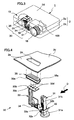
- FIG. 4 shows a detailed configuration of the angle adjusting mechanism 30.
- arrow D designates an anterior direction of the video projector 1.
- the angle adjusting mechanism 30 is comprised of a rod shaped support 31, a lock member 32 to lock the position of the support 31 with respect to the housing 2, a link lever 33 to release the locking of the support 31 by the lock member 32, a coil spring 34 to press the lock member 32 upward, and an operation button 35 which is to be operated by a user to release the locking of the support 31 by the lock member 32.
- the operation button 35 is disposed above the lock member 32 and the link lever 33 so as to be exposed outside the upper housing member 2a, partially.
- the operation button 35 has a flange 35a protruded outward and a top end portion 35e.
- a button hole 2c through which the top end portion 35e of the operation button 35 penetrates is formed on a top face 2d of the upper housing member 2a.
- the button hole 2c has substantially the same shape and size as but a little larger than those of the top end portion 35e of the operation button 35.
- a clearance between the edges of the operation button 35 and the button hole 2c becomes much smaller that that in the conventional video projector, so that visual quality of an appearance of the video projector is increased.
- the support 31, the lock member 32 and the link lever 33 are required to have high mechanical strength and high rigidity, and temperatures of them may become higher because they are disposed in the vicinity of the light source 11 which serves as a heat source in use of the video projector.
- the support 31, the lock member 32 and the link lever 33 are formed of a composite resin, for example.
- the top end portion 35e of the operation button 35 constitutes an appearance of the video projector, so that the operation button 35 is formed of a resin material of a predetermined color suitable for appearance design of the video projector 1.
- the materials of these elements are not limited to the described examples. These elements may be formed of the same material such as ABS resin, or the like.
- the support 31, the lock member 32 and the link lever 33 may be formed of a metal material.
- the support 31 is slidably provided on the housing 2 in a direction perpendicular to a bottom 2e of the housing 2, for example.
- a circular contact 31a is formed at a lower end of the support 31 so that a lower end face of the contact 31 a contacts to an installation surface on which the video projector 1 is to be installed.
- a plurality of hooking protrusions 31 b having saw-teeth shape is formed on a face of the support 31 facing the front face of the housing 2.
- the lock member 32 is provided to move in a direction perpendicular to the front face of the housing 2, that is, the anteroposterior direction of the video projector 1 in a state that the support 31 penetrates through a rectangular opening 32b of the lock member 32.
- the moving direction of the lock member 32 is perpendicular to the moving direction of the support 31.
- a hooking protrusion which engages with one of the hooking protrusion 31 b of the support 31, is formed on an inner wall of the opening 32b of the lock member 32 facing the hooking protrusions 31 b.
- An end of a locking spring 32a such as a coil spring is held on an inner face of a front wall of the housing 2 and the other end of the locking coil is held on the lock member 32, so that the lock member 32 is pressed toward the support 31 with the pressure of the locking spring 32a.
- the link lever 33 has an operation wedge 33a at a lower end thereof, which is to be wedges into a clearance between the hooking protrusion of the lock member 32 and one of the hooking protrusions 31b of the support 31 so as to release the locking of the support 31 by the lock member 32.
- the link lever 33 is formed like a crank to have an L-shape in an anterior view, for example. Since the shape of the link lever 33 in the anterior view or in a side view depends on the positions of the support 31 and the operation button 35, the shape of the link lever 33 is not so important in the subject matter of the invention.
- a mounting base 33b which is a flat plate, for example, is formed on a top end of the link lever 33. When the upper cover member 2a is attached, the mounting base 33b is disposed in the vicinity of a ceiling of the upper cover member 2a.
- the mounting base 33b has a circular center through hole 33c formed at a center thereof and a pair of side through holes 33d formed at both sides of the center through hole 33c in a widthwise direction of the video projector 1.
- the operation button 35 is mounted on the mounting base 33b, details of which will be described.
- the link lever 33 is slidably held on the lower housing member 2b in a direction perpendicular to the bottom 2e of the lower housing member 2b.
- the spring 34 is disposed below a corner of the L-shape of the link lever 33. An end of the spring 34 is held on the bottom 2e of the lower housing member 2b and the other end of the spring 34 is held on the link lever 33, so that the link lever 33 is pressed upward by the pressure of the spring 34.
- FIG. 5 and FIGs. 6A and 6B show a mounting structure of the operation button 35 and the mounting base 33b of the link lever 33.
- Arrow D in FIG. 5 designates the anterior direction of the video projector 1.
- a center post 35b with a screw hole is formed at a center on a rear face of the operation button 35, and a pair of protrusions 35c having a diameter smaller than that of the center post 35b.
- rear face of the top end portion 35e of the operation button 35 is concaved, and ribs 35d are formed to join the center post 35b and the protrusions 35c so as to increase the mechanical strengths of the center post 35b and the protrusions 35c.
- the diameter of the center through hole 33c is larger than the outer diameter of the center post 35b, and the diameter of the side through holes 33d are larger than the outer diameter of the protrusions 35c.
- the center post 35b penetrates the center through hole 33c
- the protrusions 35c penetrate the side through holes 33d of the mounting base 33b
- a screw 36 is screwed into the screw hole of the center post 35b intervening the mounting base 33b.
- the heights of the center post 35b and the protrusions 35c from the ribs 35d is larger than a thickness of the mounting base 33b and a flange diameter of the screw 36 is larger than a diameter of the center through hole 33c of the mounting base 33b, so that the operation member 35 is movably held a little on the mounting base 33b of the link lever 33 in allowances between the inner walls of the center through holes 33c and the side through holes 33d and the outer peripheries of the center post 35b and the protrusions 35c.
- the operation button 35 may be hooked with the mounting base 33b of the link lever 33 with no screw, if the operation button 35 can be held on the mounting base 33b during the attaching work of the upper housing member 2a on the bottom 2e housing member 2b.
- main elements of the video projector 1 including the optical engine 10 and the controller 20 and the angle adjusting mechanism 30 are mounted on the lower housing member 2b.
- the upper housing member 2a is attached to the lower housing member 2b from above.
- the top end portion 35e of the operation button 35 is inserted into the button hole 2c of the upper housing member 2a. Since the operation button 35 is movable with respect to the mounting base 33b in a direction parallel to the top face 2d of the upper housing member 2a on which the button hole 2c is formed (for example, in a horizontal direction), the position of the top end portion 35e of the operation button 35 can be displaced to be adjusted to the position of the button hole 2c, even though the dimensional tolerances of the elements are larger. In other words, the top end portion 35e of the operation button can be inserted into the button hole 2c even when the clearance between the edges of the operation button 35 and the button hole 2c is smaller.
- the flange 35a of the operation button, 3 5 contacts the ceiling of the upper housing member 2a when the top end portion 35e of the operation button is inserted into the button hole 2c, as shown in FIG. 6B.
- the operation button 35 and the link lever 33 are displaced downward a little against the pressure of the spring 34.
- the operation button 35 is not moved easily with respect to the link lever 33.
- the position of the operation button 35 with respect to the button hole 2c on the upper housing member 2 can be adjusted while the operation button 35 is held on the mounting base 33b of the link lever 33 when the upper housing member 2a is attached to the lower housing member 2b.
- the top end portion 35e of the operation button 35 can be inserted into the button hole 2c even when the clearance between the top end portion 35e and the edges of the button hole 2c is narrower, and thereby, visual quantity of the appearance of the video projector 1 can be increased.
- the flange 35a of the operation button 35 contacts the ceiling of the housing 2 with the pressure of the spring 34, so that the operation button 35 is held on the mounting base 33b of the link lever 33 so as not to be displaced hard.
- the optical engine 10 is not limited to the configuration that forms the image with using the color wheel 13 and the DMD 17. It, however, may be configured that the image is formed by passing the lights which are outputted from the light source through liquid crystal display panels, which are arranged corresponding to three primary colors, and synthesizing the lights passing through the liquid crystal display panels subsequently.
- the flange 35a of the operation button 35 may be formed partially along the outer periphery of the top end portion 35e. Alternatively, the operation button 35 may have no flange. Furthermore, the mounting structure of the operation button 35 and the mounting base 33b of the link lever 33a is not limited to the description and illustration of the embodiment described above, if the operation button 35 can be displaced with respect to the link lever 33. Still furthermore, the position of the operation button 35 is not limited to the top face of the housing 2, so that it may be formed on a front face or side face of the housing 2.
Landscapes
- Physics & Mathematics (AREA)
- General Physics & Mathematics (AREA)
- Projection Apparatus (AREA)
Abstract
Description
- The present invention relates to a video projector which projects images on an external screen, and especially relates to a video projector having angular adjustability to an installation surface.
- Conventionally, a video projector, which projects images on an external screen on the basis of image signals outputted from a personal computer, for example, has an angle adjusting mechanism to adjust an angle of an optical axis of a projection lens with respect to an installation surface of the video projector so as to project the image on the screen properly. A conventional angle adjusting mechanism is comprised of a rod-shaped support adjustably provided at a front center of a housing of the video projector, for example, to protrude downward from the bottom of the housing and a locking mechanism to lock the movement of the support. The locking mechanism is further linked with a operation button via a link lever to release the locking of the support by the locking mechanism. The support is locked up by the locking mechanism when it protrudes downward from the bottom of the housing of the video projector, so that the support can hold an inclined posture of the video projector. The support and the locking mechanism has a plurality of hooking points corresponding to protruding height of the support from the bottom of the housing, and thus, the angle of the optical axis of the projection lens with respect to the installation surface can be adjusted. When the operation button is operated by a user, the link lever is moved with the motion of the operation button and it releases the locking of the support by the locking mechanism, so that the support will be retracted inside the housing due to weight of the video projector.
- In such angle adjusting mechanism of the video projector, the operation button and the link lever are generally independently formed with different materials. Specifically, the inside of the housing of the video projector becomes high temperature due to heat of a light source and so on, so that an element such as the link lever which is disposed in the vicinity of a heat source or required the rigidity is formed of a metal material or a composite resin material. On the other hand, the operation button which is partially exposed outside is formed of a generic resin material in consideration of a manufacturing cost or an appearance design. Alternatively, if the link lever and the operation button were integrally formed, the shape of the integrated member might have become complex and the manufacturing cost thereof be increased. Thus, the operation button and the link lever, which are independently formed, are coupled with a screw, for example, so that the link lever is moved in conjunction with the motion of the operation button. Since the link lever is a movable member, it is held on the housing with a predetermined allowance in consideration of the dimensional tolerance.
- By the way, in such a conventional video projector, when vibrations are applied to the video projector, or sounds are outputted at megavolume from a built-in speaker of the video projector, for example, the link lever is resonated in the allowance. The resonance of the link lever further causes frictional contact of the operation button and edge of a button hole of the housing into which the operation button is inserted, so that frictional sounds are generated due to the frictional contacts of the operation button and the edge of the button hole. Such frictional sounds are rudeness to the user.
- In addition, the size of the button hole must be selected a little larger that the size of the outer shape of the operation button in consideration of the dimensional tolerances of the housing, the link lever and the operation button manufactured, so that a clearance between the edges of the button hole and the operation button becomes wider, and thus, visual quality of the video projector is deteriorated. Furthermore, the user may feel the operationality of the operation button is not so good, because the allowance of the operation button to the housing may be felt larger.
-
Japanese Laid-Open Patent Publication No. 2006-49068 2006-49068 -
Japanese Laid-Open Patent Publication No. 2004-281291 2004-281291 - The present invention is perceived to solve the problem described above, and an object of the present invention is to provide a video projector having an angle adjusting mechanism with an operation button, in which a clearance between edges of the operation button and a button hole of a housing into which the operation button is inserted can be made smaller, frictional sounds due to frictional contacts of the operation button and the edge of the button hole can be reduced, a visual quality of the video projector can be increased, and operationality to operate the operation button can be improved.
- A video projector in accordance with an aspect of the present invention comprises: a light source; an image forming unit that forms an image with using image data; a projection lens that projects the image formed by the image forming unit to a screen disposed in front of the video projector; an angle adjusting mechanism that adjusts an angle of an optical axis of the projection lens with respect to an installation surface on which the video projector is installed; and a housing that contains the light source, the image forming unit, the projection lens and the angle adjusting mechanism. The housing is comprised of an upper housing member having a button hole formed on a face thereof, and a lower housing member on which the light source, the image forming unit, the projection lens and the angle adjusting mechanism are mounted. The angle adjusting mechanism is further comprised of a support which can be pulled out downward from a bottom of the lower housing member to protrude a desired height, a lock member to lock movement of the support, a link lever to release locking of the support by the lock member when it is moved, and an operation button having a top end portion inserted into the button hole of the upper housing member and movably held on the link lever in a direction substantially parallel to the face on which the button hole is formed.
- According to such a configuration, since the operation button is movable held on the link lever in a direction substantially parallel to the face on which the button hole is formed, for example, a top face of the housing, the position of the top end portion of the operation button can be displaced to be adjusted to the position of the button hole, even though the dimensional tolerances of the elements are larger. In other words, the top end portion of the operation button can be inserted into the button hole even when the clearance between the edges of the operation button and the button hole is smaller. Consequently, a clearance between edges of the operation button and a button hole of a housing into which the operation button is inserted can be made smaller, frictional sounds due to frictional contacts of the operation button and the edge of the button hole can be reduced, a visual quality of the video projector can be increased, and operationality to operate the operation button can be improved.
- In the above mentioned configuration, it is preferable that the link lever has a mounting base on which the operation button is movably held at an end thereof; the mounting base is a flat plate having at least one hole; and the operation member has at least one protrusion on a rear face, which has a diameter smaller than the hole and penetrates through the hole.
- Furthermore, it is preferable that the hole of the mounting base is a through hole; and the protrusion of the operation member has a screw hole, and a screw having a flange diameter is larger than a diameter of the hole of the mounting base is screwed to the screw hole intervening the mounting base enabling the operation member movably held on the mounting base of the link lever.
- Alternatively, it is preferable that the mounting base has a center through hole formed at a center thereof and a pair of side trough holes formed at both sides of the center through hole in a widthwise direction of the video projector; the operation button has a center post with a screw hole formed at a center on a rear face of the operation button, and a pair of protrusions having a diameter smaller than that of the center post; a diameter of the center through hole is larger than an outer diameter of the center post, and a diameter of the side through holes is larger than an outer diameter of the protrusions; rear face of the top end portion of the operation button is concaved, and ribs are formed to join the center post and the protrusions so as to increase the mechanical strengths of the center post and the protrusions; the center post penetrates the center through hole, the protrusions penetrate the side through holes of the mounting base, and a screw is screwed into the screw hole of the center post intervening the mounting base; and heights of the center post and the protrusions from the ribs is larger than a thickness of the mounting base and a flange diameter of the screw is larger than a diameter of the center through hole of the mounting base, so that the operation member is movably held on the mounting base of the link lever.
- While the novel features of the present invention are set forth in the appended claims, the present invention will be better understood from the following detailed description taken in conjunction with the drawings.
- The present invention will be described below with reference to the annexed drawings. It is to be noted that all the drawings are shown for the purpose of illustrating the technical concept of the present invention or embodiments thereof, wherein:
- FIG 1 is a plain sectional view showing a configuration of a video projector in accordance with a preferred embodiment of the present invention;
- FIG. 2 is a block diagram showing a circuit configuration of the video projector;
- FIG. 3 is a sight through perspective view showing a configuration of the video projector;
- FIG 4 is an exploded perspective view showing a configuration of an angle adjusting mechanism of the video projector;
- FIG 5 is an exploded perspective view showing a mounting structure of an operation button on a mounting base of a link lever;
- FIG 6A is a sectional side view showing the mounting structure before attaching an upper housing member; and
- FIG. 6B is a sectional side view showing the mounting structure after attaching the upper housing member.
- A preferred embodiment of a video projector in accordance with the present invention is described below with reference to the drawings. FIG. 1 shows a
video projector 1 in accordance with the present invention. FIG 2 shows a circuit configuration of thevideo projector 1. FIG. 3 is a sight through perspective view showing a configuration of thevideo projector 1. - The
video projector 1 is used to project an enlarged image on a screen which is located in front of thevideo projector 1 by using image signals (image data) outputted from a personal computer, a video camera, or the like. - As shown in FIG 1, the
video projector 1 comprises anoptical engine 10 that is located on a front side of ahousing 2, forms an image by using image signals inputted from outside, and enlarges and projects the image on a screen located in front of thevideo projector 1, and acontroller 20 that is located on a rear side of thehousing 2, processes the image signals inputted from outside, and controls theoptical engine 10. Anangle adjusting mechanism 30, which varies an angle of thehousing 2 with respect to an installation surface, that is, the posture of thevideo projector 1, is provided at a front center portion of thehousing 2. As shown in FIG. 3, thehousing 2 is comprised of anupper housing member 2a and alower housing member 2b. Theoptical engine 10, thecontroller 20 and theangle adjusting mechanism 30 are initially mounted on thelower housing member 2b. Subsequently, theupper housing member 2a is attached to thelower housing member 2b so that theoptical engine 10, thecontroller 20 and theangle adjusting mechanism 30 are contained in thehousing 2. - As shown in FIG. 1, the
optical engine 10 includes alight source 11 such as a discharge lamp, for example, a reflector (light collecting member) 12, acolor wheel 13, amotor 14, amirror 16, a DMD (Digital Micromirror Device) 17, aprojection lens 18, and so on. Thereflector 12 reflects a light, which is outputted backward among lights outputted from thelight source 11, to a forward direction, and gathers the lights in a predetermined area. Thecolor wheel 13 is located on a light path of the light outputted from thelight source 11, and has color filters corresponding to three primary colors at a certain angular pitch, and is rotated at a constant speed. Themotor 14 rotates thecolor wheel 13 at a constant speed. Theoptical tunnel 15 of a certain inside diameter faces with the light source across thecolor wheel 13. Themirror 16 reflects a light flux, which passes through the optical tunnel, in a certain direction. The DMD (Digital Micromirror Device) 17 is located in a light path of the light flux passing through thecolor wheel 13 and then followed by theoptical tunnel 15 and themirror 16. TheDMD 17 is a cluster of micromirrors arranged in two-dimensional pattern, and changes an angle of the micromirrors according to the image signals inputted from outside, and then reflects the light flux, which passes through thecolor wheel 13, in a certain direction (a first direction) and a second direction excluding the certain direction. Theprojection lens 18 projects the light flux reflected by theDMD 17 on a screen. Theprojection lens 18 is a zoom lens that is configured by a plurality of lens elements locations of which are changeable. In the present preferred embodiment, thecolor wheel 13, theoptical tunnel 15, themirror 16, and theDMD 17 function as animage forming unit 100 which outputs the light flux projected on the screen. - The
reflector 12 has a spheroidal shape, for example, and thelight source 11 is located adjacent to one focal point of the spheroid, and thecolor wheel 13 is partially adjacent to the other focus of the spheroid. In FIG 1, thelight source 11 and thereflector 12 which are disposed in a right side of thecolor wheel 13 are enclosed with a box shapedlamp box 12a and formed as a light source unit separately formed. In contrast, in a left side of theoptical tunnel 15, adark box unit 110 is formed to reduce an impact of a stray light, and an antireflection coating is applied to an inner surface of thedark box unit 110 to absorb a reflected light. In FIG 1, apartition plate 4 is illustrated to divide a side of theoptical engine 10 from a side of thecontroller 20 in thehousing 2. Thepartition plate 4, however, is not necessary when thevideo projector 1 is actually manufactured. Thepartition plate 4 can be substituted for walls of a housing of the light source unit and the dark box unit described above. - The
controller 20 includes a DMD drive circuit (control circuit) 21 which drives theDMD 17 by using the image signals, a main controller (control circuit) 22 which wholly controls thevideo projector 1, a light source drive circuit (control circuit) 23 which drives thelight source 11, apower supply circuit 24 which provides electrical power to various units of thevideo projector 1 including theDMD drive circuit 21, themain controller 22, and the lightsource drive circuit 23, and a coolingfan 3 which generates a cooling air to cool at least thelight source 11 and thepower supply circuit 24. - The
DMD drive circuit 21 and themain controller 22 consist of a CPU, a ROM, a RAM, and so on, for example. In addition, a noise removal filter or the like is also mounted, if necessary. The lightsource drive circuit 23 is an inverter circuit which controls thelight source 11 such as a discharge lamp to keep the constant electrical power, and consists of a coil, a diode, a FET, and so on. Since the discharge lamp has a low temperature and a low voltage immediately after turned on, a large current may flow in the lamp if the electrical power is controlled to be constant, and thus a lamp life decreases. In order to avoid this trouble, the lightsource drive circuit 23 performs a warm-up to limit the current flowing in the lamp for a certain period of time after the lamp is turned on. Thepower supply circuit 24 is a circuit to generate a DC voltage power supply of 12V or 24V, for example, by using an alternate commercial power supply of 100V or 200V, for example, as an input, and consists of a coil, a diode, a FET, and so on. - As shown in FIG 1, the cooling
fan 3 takes an air into an inside of ' thehousing 2 from outside and exhausts hot air caused by an absorption of heat generated in heat sources such as thelight source 11, the lightsource drive circuit 23, thepower supply circuit 24, and so on, to the outside of thehousing 2. In the configuration shown in FIG. 1, the cooling air generated with the coolingfan 3 is partially led into the side of theoptical engine 10 and the rest of the cooling air is led into the side of thecontroller 20. - As shown in FIG. 3, the
angle adjusting mechanism 30 is disposed to take along a front face of thehousing 2 in the vicinity of thelamp box 12a. FIG. 4 shows a detailed configuration of theangle adjusting mechanism 30. In FIG 4, arrow D designates an anterior direction of thevideo projector 1. Theangle adjusting mechanism 30 is comprised of a rod shapedsupport 31, alock member 32 to lock the position of thesupport 31 with respect to thehousing 2, alink lever 33 to release the locking of thesupport 31 by thelock member 32, acoil spring 34 to press thelock member 32 upward, and anoperation button 35 which is to be operated by a user to release the locking of thesupport 31 by thelock member 32. Theoperation button 35 is disposed above thelock member 32 and thelink lever 33 so as to be exposed outside theupper housing member 2a, partially. Theoperation button 35 has aflange 35a protruded outward and atop end portion 35e. Abutton hole 2c through which thetop end portion 35e of theoperation button 35 penetrates is formed on atop face 2d of theupper housing member 2a. - The
button hole 2c has substantially the same shape and size as but a little larger than those of thetop end portion 35e of theoperation button 35. When thetop end portion 35e of theoperation button 35 is inserted into thebutton hole 2c, a clearance between the edges of theoperation button 35 and thebutton hole 2c becomes much smaller that that in the conventional video projector, so that visual quality of an appearance of the video projector is increased. Thesupport 31, thelock member 32 and thelink lever 33 are required to have high mechanical strength and high rigidity, and temperatures of them may become higher because they are disposed in the vicinity of thelight source 11 which serves as a heat source in use of the video projector. Thus, thesupport 31, thelock member 32 and thelink lever 33 are formed of a composite resin, for example. In contrast, thetop end portion 35e of theoperation button 35 constitutes an appearance of the video projector, so that theoperation button 35 is formed of a resin material of a predetermined color suitable for appearance design of thevideo projector 1. Besides, the materials of these elements are not limited to the described examples. These elements may be formed of the same material such as ABS resin, or the like. Alternatively, thesupport 31, thelock member 32 and thelink lever 33 may be formed of a metal material. - The
support 31 is slidably provided on thehousing 2 in a direction perpendicular to a bottom 2e of thehousing 2, for example. Acircular contact 31a is formed at a lower end of thesupport 31 so that a lower end face of thecontact 31 a contacts to an installation surface on which thevideo projector 1 is to be installed. A plurality of hookingprotrusions 31 b having saw-teeth shape is formed on a face of thesupport 31 facing the front face of thehousing 2. Thelock member 32 is provided to move in a direction perpendicular to the front face of thehousing 2, that is, the anteroposterior direction of thevideo projector 1 in a state that thesupport 31 penetrates through arectangular opening 32b of thelock member 32. In other words, the moving direction of thelock member 32 is perpendicular to the moving direction of thesupport 31. A hooking protrusion, which engages with one of the hookingprotrusion 31 b of thesupport 31, is formed on an inner wall of theopening 32b of thelock member 32 facing the hookingprotrusions 31 b. An end of alocking spring 32a such as a coil spring is held on an inner face of a front wall of thehousing 2 and the other end of the locking coil is held on thelock member 32, so that thelock member 32 is pressed toward thesupport 31 with the pressure of thelocking spring 32a. Thus, when the hooking protrusion of thelock member 32 engages with one of the hookingprotrusions 31b of thesupport 31, the motion of thesupport 31 is locked so that a height of thesupport 31 protruding from the bottom 2e of thehousing 2 is maintained. In other words, the position of thesupport 31 with respect to thehousing 2 is locked. - The
link lever 33 has anoperation wedge 33a at a lower end thereof, which is to be wedges into a clearance between the hooking protrusion of thelock member 32 and one of the hookingprotrusions 31b of thesupport 31 so as to release the locking of thesupport 31 by thelock member 32. As shown in FIG. 4, thelink lever 33 is formed like a crank to have an L-shape in an anterior view, for example. Since the shape of thelink lever 33 in the anterior view or in a side view depends on the positions of thesupport 31 and theoperation button 35, the shape of thelink lever 33 is not so important in the subject matter of the invention. - A mounting
base 33b which is a flat plate, for example, is formed on a top end of thelink lever 33. When theupper cover member 2a is attached, the mountingbase 33b is disposed in the vicinity of a ceiling of theupper cover member 2a. The mountingbase 33b has a circular center throughhole 33c formed at a center thereof and a pair of side throughholes 33d formed at both sides of the center throughhole 33c in a widthwise direction of thevideo projector 1. Theoperation button 35 is mounted on the mountingbase 33b, details of which will be described. - The
link lever 33 is slidably held on thelower housing member 2b in a direction perpendicular to the bottom 2e of thelower housing member 2b. Thespring 34 is disposed below a corner of the L-shape of thelink lever 33. An end of thespring 34 is held on the bottom 2e of thelower housing member 2b and the other end of thespring 34 is held on thelink lever 33, so that thelink lever 33 is pressed upward by the pressure of thespring 34. When theupper housing member 2a is attached to thelower housing member 2b with penetrating thetop end portion 35e of theoperation button 35 through thebutton hole 2c, theflange 35a of theoperation button 35 contacts the ceiling of theupper housing member 2a, so that thespring 34 is compressed a little from a natural state thereof, and thereby, thelink lever 33 is pressed upward by the pressure of thespring 34. - FIG. 5 and FIGs. 6A and 6B show a mounting structure of the
operation button 35 and the mountingbase 33b of thelink lever 33. Arrow D in FIG. 5 designates the anterior direction of thevideo projector 1. Acenter post 35b with a screw hole is formed at a center on a rear face of theoperation button 35, and a pair ofprotrusions 35c having a diameter smaller than that of thecenter post 35b. In the present embodiment, rear face of thetop end portion 35e of theoperation button 35 is concaved, andribs 35d are formed to join thecenter post 35b and theprotrusions 35c so as to increase the mechanical strengths of thecenter post 35b and theprotrusions 35c. The diameter of the center throughhole 33c is larger than the outer diameter of thecenter post 35b, and the diameter of the side throughholes 33d are larger than the outer diameter of theprotrusions 35c. - As shown in FIGs. 6A and 6b, the
center post 35b penetrates the center throughhole 33c, theprotrusions 35c penetrate the side throughholes 33d of the mountingbase 33b, and ascrew 36 is screwed into the screw hole of thecenter post 35b intervening the mountingbase 33b. The heights of thecenter post 35b and theprotrusions 35c from theribs 35d is larger than a thickness of the mountingbase 33b and a flange diameter of thescrew 36 is larger than a diameter of the center throughhole 33c of the mountingbase 33b, so that theoperation member 35 is movably held a little on the mountingbase 33b of thelink lever 33 in allowances between the inner walls of the center throughholes 33c and the side throughholes 33d and the outer peripheries of thecenter post 35b and theprotrusions 35c. Alternatively, theoperation button 35 may be hooked with the mountingbase 33b of thelink lever 33 with no screw, if theoperation button 35 can be held on the mountingbase 33b during the attaching work of theupper housing member 2a on the bottom 2ehousing member 2b. - As described above, main elements of the
video projector 1 including theoptical engine 10 and thecontroller 20 and theangle adjusting mechanism 30 are mounted on thelower housing member 2b. Then, theupper housing member 2a is attached to thelower housing member 2b from above. Hereupon, thetop end portion 35e of theoperation button 35 is inserted into thebutton hole 2c of theupper housing member 2a. Since theoperation button 35 is movable with respect to the mountingbase 33b in a direction parallel to thetop face 2d of theupper housing member 2a on which thebutton hole 2c is formed (for example, in a horizontal direction), the position of thetop end portion 35e of theoperation button 35 can be displaced to be adjusted to the position of thebutton hole 2c, even though the dimensional tolerances of the elements are larger. In other words, thetop end portion 35e of the operation button can be inserted into thebutton hole 2c even when the clearance between the edges of theoperation button 35 and thebutton hole 2c is smaller. - In addition, the
flange 35a of the operation button, 3 5 contacts the ceiling of theupper housing member 2a when thetop end portion 35e of the operation button is inserted into thebutton hole 2c, as shown in FIG. 6B. In other words, when theupper housing member 2a is attached to thelower housing member 2b, theoperation button 35 and thelink lever 33 are displaced downward a little against the pressure of thespring 34. Thus, theoperation button 35 is not moved easily with respect to thelink lever 33. - When the
operation button 35 is pushed down from the state shown in FIG 6B, thelink lever 33 is displaced downward with theoperation button 35. At this time, theoperation wedge 33a wedges into a gap between thelock member 32 and thesupport 31, so that thelock member 32 is moved forward against the pressure of thelocking spring 32a. When thelock member 32 moves forward, the hooking protrusion of thelock member 32 is disengaged from the hookingprotrusion 31b of thesupport 31, so that the locking of thesupport 31 by thelock member 32 is released and thesupport 31 can be slid to protrude downward from the bottom 2e of thehousing 2. After sliding thesupport 31 to protrude a desired height, when the pushing of theoperation button 35 is released, theoperation wedge 33a is pulled out from the gap between thelock member 32 and thesupport 31, so that thelock member 32 is moved backward by the pressure of thelocking spring 32a. When thelock member 32 moves backward, the hooking protrusion of thelock member 32 engages with one of the hookingprotrusions 31b of thesupport 31, so that thesupport 31 is locked by thelock member 32. Under such a state that thesupport 31 is protruded by a desired height from the bottom 2e of thehousing 2, when thevideo projector 1 is installed on an installation surface at three points of thecontact 31 a of thesupport 31 and other two contacts provided at both sides in a rear end portion of thehousing 2, an angle of an optical axis of theprojection lens 18 is adjusted to be a desired angle. - As described above, according to the configuration of the
video projector 1 in accordance with the present embodiment, the position of theoperation button 35 with respect to thebutton hole 2c on theupper housing member 2 can be adjusted while theoperation button 35 is held on the mountingbase 33b of thelink lever 33 when theupper housing member 2a is attached to thelower housing member 2b. Thus, thetop end portion 35e of theoperation button 35 can be inserted into thebutton hole 2c even when the clearance between thetop end portion 35e and the edges of thebutton hole 2c is narrower, and thereby, visual quantity of the appearance of thevideo projector 1 can be increased. - Furthermore, since the allowance between the
operation button 35 and thehousing 2 becomes smaller, friction sounds due to friction contacts of theoperation button 35 and the edge of thebutton hole 2c can be reduced. When theoperation button 35 is pushed down, theoperation button 35 is not shaky with respect to thehousing 2, so that the operationality of theoperation button 35 is increased. - Still furthermore, the
flange 35a of theoperation button 35 contacts the ceiling of thehousing 2 with the pressure of thespring 34, so that theoperation button 35 is held on the mountingbase 33b of thelink lever 33 so as not to be displaced hard. Thus, even when thelink lever 33 is resonated due to vibrations applied to thevideo projector 1 from outside or sounds outputted at megavolume from a built-in speaker of thevideo projector 1, frictional contacts of thetop end portion 35e of theoperation button 35 and edge of thebutton hole 2c of theupper housing member 2a rarely occurs, so that frictional sounds are rarely generated. - The present invention is not limited to the configuration as described above, and thus, various modifications are applicable without departing from the scope of the present invention. For example, the
optical engine 10 is not limited to the configuration that forms the image with using thecolor wheel 13 and theDMD 17. It, however, may be configured that the image is formed by passing the lights which are outputted from the light source through liquid crystal display panels, which are arranged corresponding to three primary colors, and synthesizing the lights passing through the liquid crystal display panels subsequently. - The
flange 35a of theoperation button 35 may be formed partially along the outer periphery of thetop end portion 35e. Alternatively, theoperation button 35 may have no flange. Furthermore, the mounting structure of theoperation button 35 and the mountingbase 33b of thelink lever 33a is not limited to the description and illustration of the embodiment described above, if theoperation button 35 can be displaced with respect to thelink lever 33. Still furthermore, the position of theoperation button 35 is not limited to the top face of thehousing 2, so that it may be formed on a front face or side face of thehousing 2.
Claims (4)
- A video projector (1) comprising:a light source (11);an image forming unit (100, 16, 17) that forms an image with using image data;a projection lens (18) that projects the image formed by the image forming unit to a screen disposed in front of the video projector;an angle adjusting mechanism (30) that adjusts an angle of an optical axis of the projection lens (18) with respect to an installation surface on which the video projector is installed; anda housing (2) that contains the light source (11), the image forming unit (100), the projection lens (18) and the angle adjusting mechanism (30), whereinthe housing (2) is comprised of an upper housing member (2a) having a button hole (2c) formed on a face (2d) thereof, and a lower housing member (2b) on which the light source (11), the image forming unit (100), the projection lens (18) and the angle adjusting mechanism (30) are mounted;the angle adjusting mechanism (30) is further comprised of a support (31) which can be pulled out downward from a bottom (2e) of the lower housing member (2b) to protrude a desired height, a lock member (32) to lock movement of the support (31), a link lever (33) to release locking of the support (31) by the lock member (32) when it is moved, and an operation button (35) having a top end portion (35e) inserted into the button hole (2c) of the upper housing member (2a) and movably held on the link lever (33) in a direction substantially parallel to the face (2d) on which the button hole (2c) is formed.
- The video projector in accordance with claim 1, wherein
the link lever (33) has a mounting base (33b) on which the operation button (35) is movably held at an end thereof;
the mounting base (33b) is a flat plate having at least one hole (33c, 33d); and
the operation member (35) has at least one protrusion (35b, 35c) on a rear face, which has a diameter smaller than the hole (33c, 33d) and penetrates through the hole (33c, 33d). - The video projector in accordance with claim 2, wherein
the hole (33c, 33d) of the mounting base (33b) is a through hole; and
the protrusion (35b) of the operation member (35) has a screw hole, and a screw (36) having a flange diameter is larger than a diameter of the hole (33c) of the mounting base (33b) is screwed to the screw hole intervening the mounting base (33b) enabling the operation member (35) movably held on the mounting base (33b) of the link lever (33). - The video projector in accordance with claim 2, wherein
the mounting base (33b) has a center through hole (33c) formed at a center thereof and a pair of side trough holes (33d) formed at both sides of the center through hole (33c) in a widthwise direction of the video projector (1);
the operation button (35) has a center post (35b) with a screw hole formed at a center on a rear face of the operation button (35), and a pair of protrusions (35c) having a diameter smaller than that of the center post (35b);
a diameter of the center through hole (33c) is larger than an outer diameter of the center post (35b), and a diameter of the side through holes (33d) is larger than an outer diameter of the protrusions (35c);
rear face of the top end portion (35e) of the operation button (35) is concaved, and ribs (35d) are formed to join the center post (35b) and the protrusions (35c) so as to increase the mechanical strengths of the center post (35b) and the protrusions (35c);
the center post (35b) penetrates the center through hole (33c), the protrusions (35c) penetrate the side through holes (33d) of the mounting base (33b), and a screw (36) is screwed into the screw hole of the center post (35b) intervening the mounting base (33b); and
heights of the center post (35b) and the protrusions (35c) from the ribs (35d) is larger than a thickness of the mounting base (33b) and a flange diameter of the screw (36) is larger than a diameter of the center through hole (33c) of the mounting base (33b), so that the operation member (35) is movably held on the mounting base (33b) of the link lever (33).
Applications Claiming Priority (1)
| Application Number | Priority Date | Filing Date | Title |
|---|---|---|---|
| JP2006145617A JP2007316320A (en) | 2006-05-25 | 2006-05-25 | Projector |
Publications (3)
| Publication Number | Publication Date |
|---|---|
| EP1860495A2 true EP1860495A2 (en) | 2007-11-28 |
| EP1860495A3 EP1860495A3 (en) | 2010-08-25 |
| EP1860495B1 EP1860495B1 (en) | 2011-10-12 |
Family
ID=38535248
Family Applications (1)
| Application Number | Title | Priority Date | Filing Date |
|---|---|---|---|
| EP07010272A Not-in-force EP1860495B1 (en) | 2006-05-25 | 2007-05-23 | Video projector |
Country Status (3)
| Country | Link |
|---|---|
| US (1) | US7828446B2 (en) |
| EP (1) | EP1860495B1 (en) |
| JP (1) | JP2007316320A (en) |
Families Citing this family (6)
| Publication number | Priority date | Publication date | Assignee | Title |
|---|---|---|---|---|
| JP2007316320A (en) * | 2006-05-25 | 2007-12-06 | Funai Electric Co Ltd | Projector |
| CN101673030B (en) * | 2008-09-12 | 2011-05-11 | 佛山普立华科技有限公司 | Projector-lifting mechanism |
| KR101114775B1 (en) | 2009-02-17 | 2012-03-05 | 삼성전자주식회사 | Focusing device for beam projector |
| CN101957548B (en) * | 2009-07-20 | 2012-01-25 | 鸿富锦精密工业(深圳)有限公司 | Elevator assembly and projector therewith |
| CN114458886B (en) * | 2022-01-25 | 2023-08-01 | 江苏经贸职业技术学院 | A kind of intelligent sorting equipment for commercial circulation |
| CN114815471B (en) * | 2022-04-20 | 2023-09-26 | 峰米(重庆)创新科技有限公司 | projection device |
Citations (2)
| Publication number | Priority date | Publication date | Assignee | Title |
|---|---|---|---|---|
| DE19703394C1 (en) | 1997-01-30 | 1998-03-12 | Whirlpool Co | Electric pushbutton switch |
| US20020113951A1 (en) | 2001-02-19 | 2002-08-22 | Kuo-Chin Huang | Adjustable height apparatus of a horizontal projector |
Family Cites Families (17)
| Publication number | Priority date | Publication date | Assignee | Title |
|---|---|---|---|---|
| FR2443129A1 (en) * | 1978-11-29 | 1980-06-27 | Serras Paulet Edouard | ELECTRICAL OR ELECTRONIC SWITCHING DEVICE FORMING PUSH BUTTON OR KEYBOARD WITH SOCKET KEYS |
| JPS6025780Y2 (en) * | 1979-03-22 | 1985-08-02 | ソニー株式会社 | push button operation device |
| DE19634051C1 (en) * | 1996-08-23 | 1997-08-28 | Telefunken Microelectron | Pushbutton switch arrangement mounted on a circuit board |
| JP2000331560A (en) | 1999-05-20 | 2000-11-30 | Kawai Musical Instr Mfg Co Ltd | switch |
| JP2002287252A (en) * | 2001-03-27 | 2002-10-03 | Seiko Epson Corp | projector |
| TW461946B (en) * | 2001-04-19 | 2001-11-01 | Primax Electronics Ltd | Adjustable stand |
| TW535483B (en) * | 2002-06-11 | 2003-06-01 | Benq Corp | Projector device |
| JP2004281291A (en) | 2003-03-18 | 2004-10-07 | Matsushita Electric Ind Co Ltd | Electronic equipment and push buttons used for it |
| DE10316934B4 (en) * | 2003-04-12 | 2007-12-13 | Electrolux Home Products Corporation N.V. | Keypad for insertion into a control surface of a household appliance |
| WO2004110047A2 (en) * | 2003-06-02 | 2004-12-16 | Infocus Corporation | Elevator assembly for a projection device |
| TWI231884B (en) * | 2003-10-09 | 2005-05-01 | Coretronic Corp | Adjusting structure of projector |
| JP2006049068A (en) | 2004-08-04 | 2006-02-16 | Calsonic Kansei Corp | Mounting structure for push knob |
| TWI281592B (en) * | 2004-09-01 | 2007-05-21 | Benq Corp | Adjustment mechanism and electronic device utilizing the same |
| TWI250369B (en) * | 2004-11-16 | 2006-03-01 | Benq Corp | Adjustment mechanism and electronic device utilizing the same |
| TWI266946B (en) * | 2005-03-09 | 2006-11-21 | Coretronic Corp | Elevating mechanism |
| TWI275898B (en) * | 2005-04-29 | 2007-03-11 | Coretronic Corp | Elevating structure |
| JP2007316320A (en) * | 2006-05-25 | 2007-12-06 | Funai Electric Co Ltd | Projector |
-
2006
- 2006-05-25 JP JP2006145617A patent/JP2007316320A/en not_active Withdrawn
-
2007
- 2007-05-23 EP EP07010272A patent/EP1860495B1/en not_active Not-in-force
- 2007-05-24 US US11/753,285 patent/US7828446B2/en not_active Expired - Fee Related
Patent Citations (2)
| Publication number | Priority date | Publication date | Assignee | Title |
|---|---|---|---|---|
| DE19703394C1 (en) | 1997-01-30 | 1998-03-12 | Whirlpool Co | Electric pushbutton switch |
| US20020113951A1 (en) | 2001-02-19 | 2002-08-22 | Kuo-Chin Huang | Adjustable height apparatus of a horizontal projector |
Also Published As
| Publication number | Publication date |
|---|---|
| US20070273840A1 (en) | 2007-11-29 |
| JP2007316320A (en) | 2007-12-06 |
| EP1860495B1 (en) | 2011-10-12 |
| US7828446B2 (en) | 2010-11-09 |
| EP1860495A3 (en) | 2010-08-25 |
Similar Documents
| Publication | Publication Date | Title |
|---|---|---|
| EP1860495B1 (en) | Video projector | |
| EP1860496A1 (en) | Video projector | |
| JP4357469B2 (en) | Projector device | |
| JP2002365725A (en) | Projection lens shift mechanism | |
| JP2000029134A (en) | Projection display device | |
| US10225531B2 (en) | Image display unit, image projection unit, and image projection apparatus | |
| US20160274444A1 (en) | Image projection apparatus, and light source unit | |
| KR100621184B1 (en) | Optical engine and image projection apparatus including the same | |
| JP2011013549A (en) | Lens barrel shift mechanism and projector | |
| EP4390535A1 (en) | Angle controlling apparatus and angle controlling method for electronic device | |
| US6994440B2 (en) | Elevator assembly for a projection device | |
| JP2005073182A (en) | Rear projection type projector device and rear projection type projector system | |
| JP3092508U (en) | Mirror adjustment structure of image display projector | |
| JP4386961B2 (en) | Projector device | |
| JP2007078734A (en) | Projector device | |
| KR20140091835A (en) | Bracket for projector | |
| JP4703678B2 (en) | Projector device | |
| US20130321778A1 (en) | Image projection apparatus | |
| JP2004317986A (en) | Moving device, lens barrel support device, and projection display device | |
| JP2000231078A (en) | Video projection device | |
| JP4115476B2 (en) | Projector device | |
| KR100219650B1 (en) | Apparatus to control the center of lens unit for projector | |
| JP4241698B2 (en) | Projector device | |
| JP4423998B2 (en) | Optical apparatus and projector | |
| JP4934303B2 (en) | Projector device |
Legal Events
| Date | Code | Title | Description |
|---|---|---|---|
| PUAI | Public reference made under article 153(3) epc to a published international application that has entered the european phase |
Free format text: ORIGINAL CODE: 0009012 |
|
| AK | Designated contracting states |
Kind code of ref document: A2 Designated state(s): AT BE BG CH CY CZ DE DK EE ES FI FR GB GR HU IE IS IT LI LT LU LV MC MT NL PL PT RO SE SI SK TR |
|
| AX | Request for extension of the european patent |
Extension state: AL BA HR MK YU |
|
| PUAL | Search report despatched |
Free format text: ORIGINAL CODE: 0009013 |
|
| AK | Designated contracting states |
Kind code of ref document: A3 Designated state(s): AT BE BG CH CY CZ DE DK EE ES FI FR GB GR HU IE IS IT LI LT LU LV MC MT NL PL PT RO SE SI SK TR |
|
| AX | Request for extension of the european patent |
Extension state: AL BA HR MK RS |
|
| RIC1 | Information provided on ipc code assigned before grant |
Ipc: H01H 13/14 20060101ALI20100716BHEP Ipc: G03B 21/14 20060101AFI20071004BHEP |
|
| 17P | Request for examination filed |
Effective date: 20110111 |
|
| RIC1 | Information provided on ipc code assigned before grant |
Ipc: H01H 13/14 20060101ALI20110217BHEP Ipc: G03B 21/14 20060101AFI20110217BHEP |
|
| GRAP | Despatch of communication of intention to grant a patent |
Free format text: ORIGINAL CODE: EPIDOSNIGR1 |
|
| AKX | Designation fees paid |
Designated state(s): DE FR GB |
|
| GRAS | Grant fee paid |
Free format text: ORIGINAL CODE: EPIDOSNIGR3 |
|
| GRAA | (expected) grant |
Free format text: ORIGINAL CODE: 0009210 |
|
| AK | Designated contracting states |
Kind code of ref document: B1 Designated state(s): DE FR GB |
|
| REG | Reference to a national code |
Ref country code: GB Ref legal event code: FG4D |
|
| REG | Reference to a national code |
Ref country code: DE Ref legal event code: R096 Ref document number: 602007017701 Country of ref document: DE Effective date: 20111208 |
|
| REG | Reference to a national code |
Ref country code: DE Ref legal event code: R082 Ref document number: 602007017701 Country of ref document: DE Representative=s name: GRUENECKER, KINKELDEY, STOCKMAIR & SCHWANHAEUS, DE Ref country code: DE Ref legal event code: R082 Ref document number: 602007017701 Country of ref document: DE Representative=s name: GRUENECKER PATENT- UND RECHTSANWAELTE PARTG MB, DE |
|
| PLBE | No opposition filed within time limit |
Free format text: ORIGINAL CODE: 0009261 |
|
| STAA | Information on the status of an ep patent application or granted ep patent |
Free format text: STATUS: NO OPPOSITION FILED WITHIN TIME LIMIT |
|
| 26N | No opposition filed |
Effective date: 20120713 |
|
| REG | Reference to a national code |
Ref country code: DE Ref legal event code: R097 Ref document number: 602007017701 Country of ref document: DE Effective date: 20120713 |
|
| PGFP | Annual fee paid to national office [announced via postgrant information from national office to epo] |
Ref country code: GB Payment date: 20130522 Year of fee payment: 7 Ref country code: DE Payment date: 20130515 Year of fee payment: 7 |
|
| PGFP | Annual fee paid to national office [announced via postgrant information from national office to epo] |
Ref country code: FR Payment date: 20130531 Year of fee payment: 7 |
|
| REG | Reference to a national code |
Ref country code: DE Ref legal event code: R119 Ref document number: 602007017701 Country of ref document: DE |
|
| GBPC | Gb: european patent ceased through non-payment of renewal fee |
Effective date: 20140523 |
|
| REG | Reference to a national code |
Ref country code: FR Ref legal event code: ST Effective date: 20150130 |
|
| REG | Reference to a national code |
Ref country code: DE Ref legal event code: R119 Ref document number: 602007017701 Country of ref document: DE Effective date: 20141202 |
|
| PG25 | Lapsed in a contracting state [announced via postgrant information from national office to epo] |
Ref country code: DE Free format text: LAPSE BECAUSE OF NON-PAYMENT OF DUE FEES Effective date: 20141202 |
|
| PG25 | Lapsed in a contracting state [announced via postgrant information from national office to epo] |
Ref country code: GB Free format text: LAPSE BECAUSE OF NON-PAYMENT OF DUE FEES Effective date: 20140523 Ref country code: FR Free format text: LAPSE BECAUSE OF NON-PAYMENT OF DUE FEES Effective date: 20140602 |