EP1860339A1 - Shaft body holding structure, variable intake valve, and intake device - Google Patents
Shaft body holding structure, variable intake valve, and intake device Download PDFInfo
- Publication number
- EP1860339A1 EP1860339A1 EP06715377A EP06715377A EP1860339A1 EP 1860339 A1 EP1860339 A1 EP 1860339A1 EP 06715377 A EP06715377 A EP 06715377A EP 06715377 A EP06715377 A EP 06715377A EP 1860339 A1 EP1860339 A1 EP 1860339A1
- Authority
- EP
- European Patent Office
- Prior art keywords
- shaft
- holding
- bearing
- shaft member
- gap
- Prior art date
- Legal status (The legal status is an assumption and is not a legal conclusion. Google has not performed a legal analysis and makes no representation as to the accuracy of the status listed.)
- Withdrawn
Links
- 238000010276 construction Methods 0.000 claims abstract description 65
- 238000000638 solvent extraction Methods 0.000 claims description 34
- 238000004891 communication Methods 0.000 claims description 17
- 230000009467 reduction Effects 0.000 description 12
- 230000008901 benefit Effects 0.000 description 3
- 238000003780 insertion Methods 0.000 description 3
- 230000037431 insertion Effects 0.000 description 3
- 238000004519 manufacturing process Methods 0.000 description 3
- 230000002265 prevention Effects 0.000 description 3
- 238000006073 displacement reaction Methods 0.000 description 2
- 238000002485 combustion reaction Methods 0.000 description 1
- 230000000694 effects Effects 0.000 description 1
- 230000005489 elastic deformation Effects 0.000 description 1
- 230000002708 enhancing effect Effects 0.000 description 1
- 230000002452 interceptive effect Effects 0.000 description 1
- 239000000463 material Substances 0.000 description 1
- 238000000034 method Methods 0.000 description 1
- 230000004048 modification Effects 0.000 description 1
- 238000012986 modification Methods 0.000 description 1
- 230000002093 peripheral effect Effects 0.000 description 1
- 230000008569 process Effects 0.000 description 1
- 239000011347 resin Substances 0.000 description 1
- 229920005989 resin Polymers 0.000 description 1
- 238000003466 welding Methods 0.000 description 1
Images



Classifications
-
- F—MECHANICAL ENGINEERING; LIGHTING; HEATING; WEAPONS; BLASTING
- F02—COMBUSTION ENGINES; HOT-GAS OR COMBUSTION-PRODUCT ENGINE PLANTS
- F02D—CONTROLLING COMBUSTION ENGINES
- F02D9/00—Controlling engines by throttling air or fuel-and-air induction conduits or exhaust conduits
- F02D9/08—Throttle valves specially adapted therefor; Arrangements of such valves in conduits
- F02D9/10—Throttle valves specially adapted therefor; Arrangements of such valves in conduits having pivotally-mounted flaps
- F02D9/1035—Details of the valve housing
- F02D9/106—Sealing of the valve shaft in the housing, e.g. details of the bearings
-
- F—MECHANICAL ENGINEERING; LIGHTING; HEATING; WEAPONS; BLASTING
- F02—COMBUSTION ENGINES; HOT-GAS OR COMBUSTION-PRODUCT ENGINE PLANTS
- F02B—INTERNAL-COMBUSTION PISTON ENGINES; COMBUSTION ENGINES IN GENERAL
- F02B27/00—Use of kinetic or wave energy of charge in induction systems, or of combustion residues in exhaust systems, for improving quantity of charge or for increasing removal of combustion residues
- F02B27/02—Use of kinetic or wave energy of charge in induction systems, or of combustion residues in exhaust systems, for improving quantity of charge or for increasing removal of combustion residues the systems having variable, i.e. adjustable, cross-sectional areas, chambers of variable volume, or like variable means
-
- F—MECHANICAL ENGINEERING; LIGHTING; HEATING; WEAPONS; BLASTING
- F02—COMBUSTION ENGINES; HOT-GAS OR COMBUSTION-PRODUCT ENGINE PLANTS
- F02B—INTERNAL-COMBUSTION PISTON ENGINES; COMBUSTION ENGINES IN GENERAL
- F02B27/00—Use of kinetic or wave energy of charge in induction systems, or of combustion residues in exhaust systems, for improving quantity of charge or for increasing removal of combustion residues
- F02B27/02—Use of kinetic or wave energy of charge in induction systems, or of combustion residues in exhaust systems, for improving quantity of charge or for increasing removal of combustion residues the systems having variable, i.e. adjustable, cross-sectional areas, chambers of variable volume, or like variable means
- F02B27/0226—Use of kinetic or wave energy of charge in induction systems, or of combustion residues in exhaust systems, for improving quantity of charge or for increasing removal of combustion residues the systems having variable, i.e. adjustable, cross-sectional areas, chambers of variable volume, or like variable means characterised by the means generating the charging effect
- F02B27/0247—Plenum chambers; Resonance chambers or resonance pipes
- F02B27/0252—Multiple plenum chambers or plenum chambers having inner separation walls, e.g. comprising valves for the same group of cylinders
-
- F—MECHANICAL ENGINEERING; LIGHTING; HEATING; WEAPONS; BLASTING
- F02—COMBUSTION ENGINES; HOT-GAS OR COMBUSTION-PRODUCT ENGINE PLANTS
- F02B—INTERNAL-COMBUSTION PISTON ENGINES; COMBUSTION ENGINES IN GENERAL
- F02B27/00—Use of kinetic or wave energy of charge in induction systems, or of combustion residues in exhaust systems, for improving quantity of charge or for increasing removal of combustion residues
- F02B27/02—Use of kinetic or wave energy of charge in induction systems, or of combustion residues in exhaust systems, for improving quantity of charge or for increasing removal of combustion residues the systems having variable, i.e. adjustable, cross-sectional areas, chambers of variable volume, or like variable means
- F02B27/0226—Use of kinetic or wave energy of charge in induction systems, or of combustion residues in exhaust systems, for improving quantity of charge or for increasing removal of combustion residues the systems having variable, i.e. adjustable, cross-sectional areas, chambers of variable volume, or like variable means characterised by the means generating the charging effect
- F02B27/0268—Valves
- F02B27/0273—Flap valves
-
- F—MECHANICAL ENGINEERING; LIGHTING; HEATING; WEAPONS; BLASTING
- F02—COMBUSTION ENGINES; HOT-GAS OR COMBUSTION-PRODUCT ENGINE PLANTS
- F02M—SUPPLYING COMBUSTION ENGINES IN GENERAL WITH COMBUSTIBLE MIXTURES OR CONSTITUENTS THEREOF
- F02M35/00—Combustion-air cleaners, air intakes, intake silencers, or induction systems specially adapted for, or arranged on, internal-combustion engines
- F02M35/10—Air intakes; Induction systems
- F02M35/10006—Air intakes; Induction systems characterised by the position of elements of the air intake system in direction of the air intake flow, i.e. between ambient air inlet and supply to the combustion chamber
- F02M35/10026—Plenum chambers
- F02M35/10065—Valves arranged in the plenum chamber
-
- F—MECHANICAL ENGINEERING; LIGHTING; HEATING; WEAPONS; BLASTING
- F16—ENGINEERING ELEMENTS AND UNITS; GENERAL MEASURES FOR PRODUCING AND MAINTAINING EFFECTIVE FUNCTIONING OF MACHINES OR INSTALLATIONS; THERMAL INSULATION IN GENERAL
- F16C—SHAFTS; FLEXIBLE SHAFTS; ELEMENTS OR CRANKSHAFT MECHANISMS; ROTARY BODIES OTHER THAN GEARING ELEMENTS; BEARINGS
- F16C35/00—Rigid support of bearing units; Housings, e.g. caps, covers
- F16C35/02—Rigid support of bearing units; Housings, e.g. caps, covers in the case of sliding-contact bearings
-
- F—MECHANICAL ENGINEERING; LIGHTING; HEATING; WEAPONS; BLASTING
- F02—COMBUSTION ENGINES; HOT-GAS OR COMBUSTION-PRODUCT ENGINE PLANTS
- F02B—INTERNAL-COMBUSTION PISTON ENGINES; COMBUSTION ENGINES IN GENERAL
- F02B27/00—Use of kinetic or wave energy of charge in induction systems, or of combustion residues in exhaust systems, for improving quantity of charge or for increasing removal of combustion residues
- F02B27/02—Use of kinetic or wave energy of charge in induction systems, or of combustion residues in exhaust systems, for improving quantity of charge or for increasing removal of combustion residues the systems having variable, i.e. adjustable, cross-sectional areas, chambers of variable volume, or like variable means
- F02B27/0205—Use of kinetic or wave energy of charge in induction systems, or of combustion residues in exhaust systems, for improving quantity of charge or for increasing removal of combustion residues the systems having variable, i.e. adjustable, cross-sectional areas, chambers of variable volume, or like variable means characterised by the charging effect
- F02B27/021—Resonance charging
-
- F—MECHANICAL ENGINEERING; LIGHTING; HEATING; WEAPONS; BLASTING
- F02—COMBUSTION ENGINES; HOT-GAS OR COMBUSTION-PRODUCT ENGINE PLANTS
- F02D—CONTROLLING COMBUSTION ENGINES
- F02D9/00—Controlling engines by throttling air or fuel-and-air induction conduits or exhaust conduits
- F02D9/08—Throttle valves specially adapted therefor; Arrangements of such valves in conduits
- F02D9/10—Throttle valves specially adapted therefor; Arrangements of such valves in conduits having pivotally-mounted flaps
- F02D9/1035—Details of the valve housing
- F02D9/104—Shaping of the flow path in the vicinity of the flap, e.g. having inserts in the housing
- F02D9/1045—Shaping of the flow path in the vicinity of the flap, e.g. having inserts in the housing for sealing of the flow in closed flap position, e.g. the housing forming a valve seat
-
- F—MECHANICAL ENGINEERING; LIGHTING; HEATING; WEAPONS; BLASTING
- F02—COMBUSTION ENGINES; HOT-GAS OR COMBUSTION-PRODUCT ENGINE PLANTS
- F02M—SUPPLYING COMBUSTION ENGINES IN GENERAL WITH COMBUSTIBLE MIXTURES OR CONSTITUENTS THEREOF
- F02M35/00—Combustion-air cleaners, air intakes, intake silencers, or induction systems specially adapted for, or arranged on, internal-combustion engines
- F02M35/10—Air intakes; Induction systems
- F02M35/10091—Air intakes; Induction systems characterised by details of intake ducts: shapes; connections; arrangements
- F02M35/10131—Ducts situated in more than one plane; Ducts of one plane crossing ducts of another plane
-
- F—MECHANICAL ENGINEERING; LIGHTING; HEATING; WEAPONS; BLASTING
- F02—COMBUSTION ENGINES; HOT-GAS OR COMBUSTION-PRODUCT ENGINE PLANTS
- F02M—SUPPLYING COMBUSTION ENGINES IN GENERAL WITH COMBUSTIBLE MIXTURES OR CONSTITUENTS THEREOF
- F02M35/00—Combustion-air cleaners, air intakes, intake silencers, or induction systems specially adapted for, or arranged on, internal-combustion engines
- F02M35/10—Air intakes; Induction systems
- F02M35/104—Intake manifolds
- F02M35/116—Intake manifolds for engines with cylinders in V-arrangement or arranged oppositely relative to the main shaft
-
- Y—GENERAL TAGGING OF NEW TECHNOLOGICAL DEVELOPMENTS; GENERAL TAGGING OF CROSS-SECTIONAL TECHNOLOGIES SPANNING OVER SEVERAL SECTIONS OF THE IPC; TECHNICAL SUBJECTS COVERED BY FORMER USPC CROSS-REFERENCE ART COLLECTIONS [XRACs] AND DIGESTS
- Y02—TECHNOLOGIES OR APPLICATIONS FOR MITIGATION OR ADAPTATION AGAINST CLIMATE CHANGE
- Y02T—CLIMATE CHANGE MITIGATION TECHNOLOGIES RELATED TO TRANSPORTATION
- Y02T10/00—Road transport of goods or passengers
- Y02T10/10—Internal combustion engine [ICE] based vehicles
- Y02T10/12—Improving ICE efficiencies
Definitions
- the present invention relates to a shaft-member holding construction for holding a shaft member which supports a rotary member, as well as to a variable intake valve using the holding construction and an intake apparatus using the variable intake valve.
- variable intake valve included in a multi-cylinder internal combustion engine.
- This variable intake valve is incorporated in a surge tank constituting an air intake system.
- intake passages communicated with respective particular cylinders are partitioned from each other by a partitioning wall.
- the variable intake valve is used for adjusting an aperture or an opening degree of a communication opening provided in the partitioning wall, thereby to adjust amounts of air to be supplied to the respective cylinders (see Patent Document 1 for example).
- this variable intake valve is first attached to a valve holder, which then in turn is attached to the surge tank.
- the valve holder includes a flange portion for its attachment to the partitioning wall and a side wall portion which projects perpendicularly from an attaching surface of the flange portion. Further, at the center portion of the valve holder, there is provided a valve hole whose aperture is adjusted by the variable intake valve.
- shaft-member supporting holes for supporting the shaft member and bearings are mounted within these shaft-member supporting holes so that the shaft member is supported to these bearings.
- the shaft member For the attachment of the shaft member, the shaft member needs to be inserted into the shaft-member supporting holes along their axial direction. For this reason, when attaching the shaft member and the valve body to the valve holder, this was done by e.g. inserting the shaft member into one of the shaft-member supporting holes along the extending direction of the shaft member, inserting the leading end of this shaft member into the other shaft-member supporting hole and then bolt-fixing the valve body to this shaft member.
- Patent Document Japanese Patent Application "Kokai" No. 2004-116357 .
- valve body is attached to the shaft member after this shaft member has been inserted into the shaft-member supporting holes, additional working is needed in the attaching portions of the shaft member and the rotary member. As a result, the assembly process of the variable intake valve would be troublesome which led to increase in manufacture cost.
- the shaft member integral with the valve body.
- the shaft member is to be inserted into the shaft-member supporting hole along the longitudinal direction from the outside of the valve holder, there will occur interference between the valve body and the valve holder, thus preventing appropriate setting of the angle of insertion of the shaft member into the shaft-member supporting hole.
- the present invention has been made in view of the above-described problems of the art.
- the object of the invention is to provide a shaft-member holding construction, a variable intake valve using the holding construction and an intake apparatus using the variable intake valve, all of which allow attachment of various types of shaft members to be done easily.
- a shaft-member holding construction comprises:
- the bearing holding member has a gap capable of receiving the shaft member from a radial direction relative to the axial direction.
- the conventional necessity of inserting the shaft member along the axial direction so that the attachment of the shaft member can be done easily.
- the shaft member often has a great length. If there is imposed restriction in the working space available in those portions where the shaft member is to be attached, especially along the extending direction of the shaft member, the attachment of the shaft member would otherwise be difficult, even if no rotary member is attached thereto.
- the attachment can be done from the radial direction relative to the axis of the shaft member. Therefore, the attachment operation can be done extremely smoothly.
- said shaft member includes a chamfered portion at a portion thereof to be received by said bearing holding member.
- said gap is open on one side of the bearing holding member along the axial direction, and a wall portion is provided adjacent the other end of said gap opposite to said opening.
- the gap is open on one side of the bearing holding member along the axial direction, and a wall portion is provided adjacent the other end of gap opposite to its opening side.
- This construction is advantageous for e.g. holding an extreme end portion of the shaft member by the bearing holding member. More particularly, the above construction facilitates the assembly of the shaft member and also prevents displacement of the once attached shaft member along its axial direction. Consequently, the shaft member can be held in an even more reliable manner.
- the holding construction further comprises a gap closing member for closing said gap.
- the bearing holding member could otherwise suffer from correspondingly reduced rigidity, which may lead to reduction in the force for holding the shaft member and the bearing, hence, eventually to inadvertent withdrawal of the shaft member and/or the bearing from the radial direction.
- the gap closing member for closing the gap of the bearing holding member, such inadvertent withdrawal of the shaft member and/or the bearing from the radial direction may be avoided reliably.
- the holding construction further comprises an external force applying member for coming into contact with the bearing holding member so as to prevent widening of said gap.
- the bearing holding member could otherwise suffer from correspondingly reduced rigidity, which may lead to reduction in the force for holding the shaft member and the bearing, hence, eventually to inadvertent withdrawal of the shaft member or the bearing from the radial direction.
- the rigidity of the bearing holding member can be enhanced. As a result, through prevention of the widening of the gap, the inadvertent withdrawal of the bearing and/or the shaft member can be prevented in an effective manner.
- said shaft-member holding construction is attached to an opening formed in a partitioning wall which divides an inner space of a surge tank constituting an intake apparatus, and said gap closing member is a concave portion provided in said partitioning wall for accommodating said bearing holding member therein when said holding construction is attached to said partitioning wall.
- a concave portion formed in a partitioning wall of a surge tank is provided as the gap closing member.
- a part of the member to which the shaft holding construction is to be attached is utilized as the gap closing member.
- the shaft-member holding construction can reliably prevent inadvertent withdrawal of the bearing and/or the shaft member from the radial direction.
- said shaft-member holding construction is attached to an opening formed in a partitioning wall which divides an inner space of a surge tank constituting an intake apparatus, and said external force applying member is a concave portion provided in said partitioning wall for accommodating said bearing holding member therein when said holding construction is attached to said partitioning wall.
- a concave portion formed in a partitioning wall of a surge tank is provided as the external force applying closing member.
- a part of the member to which the shaft holding construction is to be attached is utilized as the external force applying member.
- the shaft-member holding construction can reliably prevent inadvertent withdrawal of the bearing or the shaft member from the radial direction.
- a variable intake valve to be attached to an opening formed in an partitioning wall for dividing an inner space of a surge tank constituting an intake apparatus, the intake valve comprising:
- the above-described shaft-member holding construction is applied to a variable intake valve.
- the attaching operation of the valve body to the valve holder can be effected in an extremely smooth manner.
- the manufacturing cost of the variable intake valve can be reduced.
- an intake apparatus comprises:
- variable intake valve which can be assembled easily is applied to an intake apparatus. Hence, the manufacturing cost of the variable apparatus can be reduced.
- a shaft-member retaining construction to which the present invention relates can be used in e.g. various portions of a vehicle engine.
- the inventive holding construction is used in a variable intake valve of an air intake system included therein.
- Fig. 1 shows a surge tank 7 to be connected to an intake port of an engine.
- This surge tank 7 is for use with a vertical six-cylinder engine.
- the inside of the tank 7 is divided into a first chamber 7a and a second chamber 7b by a partitioning wall 8.
- the first chamber 7a is communicated with intake manifolds M1, M2, M3 connected to three cylinders disposed on one side, whereas the second chamber 7b is communicated with intake manifolds M4, M5, M6 connected to further three cylinders disposed on the other side.
- the partitioning wall 8 defines a communication opening 33 for communicating the first chamber 7a and the second chamber 7b to each other.
- the aperture or the opening degree of this communication hole 33 is adjusted in accordance with revolution of the engine.
- the communication opening 33 is provided for relieving such inconvenience occurring in the air intake. Normally, during an idling or a low speed rotation of the engine, the communication hole 33 is closed. Wherein, when the rotational speed of the engine exceeds a predetermined value, the communication opening 33 will be fully opened.
- valve 1 The aperture, or the opening degree, of the communication opening 33, is adjusted by means of a variable intake valve 1 (to be referred to simply as "valve 1", hereinafter).
- this valve 1 includes an approximately rectangular valve body 2a, as a rotary member 2, and a shaft member 4 supporting this valve body 2a.
- the valve body 2a and the shaft member 4 can be formed integral with each other or can be an assembly of separately formed members.
- the shape of the valve body 2a is not limited to the approximately rectangular shape, but can instead be any other shape such as circular, oval, trapezoidal, square shapes.
- seal member 6 formed of e.g. rubber. This seal member 6 maintains a closed condition of the communication opening 33 when the valve 1 is under its closed posture.
- the seal member 6 can be provided instead to the communication opening 33.
- the communication opening 33 is provided in a valve holder 3.
- this valve holder 3 is attached to an opening 81 formed in the partitioning wall 8, the first chamber 7a and the second chamber 7b can be communicated with each other via the communication opening 33.
- the attachment of the valve holder 3 to the partitioning wall 8 can be realized in various ways such as welding, screw-fastening, press-fitting, etc.
- This valve holder 3 includes bearing holding members for rotatably supporting the shaft member 4.
- the shaft member 4 is driven to rotate by means of an actuator 9 provided outside the surge tank 7.
- Fig. 2 illustrates opening/closing conditions of the valve 1.
- the communication opening 33 is closed as shown by solid lines in the figure.
- the communication opening 33 is fully opened as shown by two-dot lines in the same figure.
- the shaft-member holding construction according to the present invention is shown in details in Figs. 3 through 5.
- valve member 2a as the rotary member 2, and the shaft member 4 for supporting the valve body 2a are formed integral with each other.
- This shaft member 4 is supported by the bearing holding members provided adjacent opposed longitudinal ends of the valve holder 3. Between the shaft member and each bearing holding member, there is provided a bearing 5 for supporting the shaft member 4 while allowing smooth rotation of this shaft member 4.
- the shaft member 4 can be attached to the bearing holding members from a radial direction relative to the axial direction of the shaft member 4.
- the bearing holding members there are employed two types of holding members, i.e. a first bearing holding member 31 and a second bearing holding member 32.
- the first bearing holding member 31 has, at its top portion, a gap 31 b extending over the entire length of this first bearing holding member 31 along the axial direction of the shaft member 4.
- the second bearing holding member 32 has, at its top portion, a gap 32b extending over a limited part of the length of this second bearing holding member 32 along the axial direction of the shaft member 4. With both of these gaps 31b, 32b, their width is set slighter greater than the outer diameter of the shaft member 4.
- the shaft member can be attached by being inserted therethrough.
- a component having such shaft member 4 having a great length is often used as variety of mechanical components, not limited in its use to the variable intake valve.
- the shaft member 4 can be attached from the radial direction of the bearing holding member. Accordingly, the attachment of various kinds of rotary members 2 can be effected very easily.
- the gap 32b provided in the second bearing holding member 32 is open to one side of this second bearing holding member 32 along the axial direction. That is, the gap 32b is not to be provided at a portion of the second bearing holding member 32. In this case, during attachment of the shaft member 4, the position where the shaft member 4 is brought nearby will be restricted so as to prevent an end of the shaft member 4 from interfering with the top of the second bearing holding member 32. However, as the portion of the top portion of the second bearing holding member 32 extends continuously or un-interruptedly to form an annular shape, this bearing holding member can have a sufficient strength.
- the width of the gaps 31b, 82b can be set slightly smaller than the outer diameter of the shaft member 4 also. Namely, in this case, the shaft member 4 will be pressed against the gaps 31b, 32b so as to cause temporary elastic deformation in the at least one of the shaft member 4 and the bearing holding members 31, 32, the shaft member 4 can be inserted into the gaps 31b, 32b.
- the width of the gaps 31b, 32b is slightly smaller than the outer diameter of the shaft member 4, it is possible to prevent inadvertent withdrawal of the shaft member 4 from the gaps 31b, 32b in a reliable manner. Hence, there is achieved such advantage as the temporary assembly of the shaft member being facilitated.
- the first bearing holding member 31 and the second bearing holding member 32 respectively include a first opening 31a and a second opening 31b both capable of receiving the respective bearings 5 along the axial direction of the shaft member 4.
- the bearing 5 exhibits a substantially cylindrical shape.
- the inner diameter dimensions of these first and second openings 31a, 32a are set slightly smaller than the outer diameter of the bearing 5.
- a lid member (not shown) will be attached from a near side in the direction normal to the plane of Fig. 1.
- a first concave portion 8a and a second concave portion 8b for covering the bearing holding members.
- the first concave portion 8a functions as a gap closing member 11 for closing the gap 31b of the first bearing holding member 31. Namely, due to the presence of the gap 31b therein, the first bearing holding member 31 suffers some reduction in its rigidity, which can lead to some reduction in its holding force for holding the shaft member 4. As a result, there is the risk of the shaft member 4 or the bearings 5 being withdrawn inadvertently in that direction. With the above-described construction, however, as the gap 31b is closed with using the first concave portion 8a of the lid member, such inadvertent withdrawal of the bearings 5 and/or the shaft member 4 can be prevented reliably.
- the side of the partitioning wall 8 to which the variable intake valve 1 is to be attached is adapted to function as the gap closing member 11, there is no necessity of providing such gap closing member 11 separately. Consequently, the number of components can be reduced and the cost reduction is made possible.
- this first concave portion 31 b will be adapted to function as an external force applying member 12 as this first concave portion 31b comes into contact with respective portions of the first bearing holding member 31 present across the gap 31b so as to prevent further widening or narrowing therebetween.
- the second concave portion 8b provides the following additional functions also.
- the second concave portion 8b is configured to cover also the end portion of the second bearing holding portion 32 relative to the axial direction of the shaft member 4.
- the end portion of the shaft member 4 is contained within the second bearing holding portion 32, when the second concave portion 8b forms a wall portion 8c adjacent the end face of the end of the shaft member 4.
- first concave portion 8a and the second concave portion 8b need not necessarily be provided in the lid member for the surge tank 7. Instead, these can be provided as separately prepared members which are to be attached to the bearing holding members. In this case, these separately prepared members may be adapted to act as the gap closing member 11 and/or the external force applying member 12.
- the shaft member 4 has been described as having simply a circular cross section. Instead, as shown in Fig. 8, the shaft member 4 can include chamfered portions 4a at portions thereof to be received by the bearing holding members 31, 32.
- the manner of forming the chamfered portions 4a is not limited to the one shown in Fig. 8 in which flattened faces are provided at two portions or sides. Instead, only one side can be chamfered. Further alternatively, the shaft member 4 can have a polygonal or oval cross sectional shape.
- the gaps 31b, 32b are provided at the top portions of the respective bearing holding members.
- the invention is not limited to such construction. Instead, these gaps 31b, 32b can be provided in e.g. lateral faces of the bearing holding members with an offset from each other.
- the inventive shaft-member holding construction is applied to a variable intake valve for use in an automobile.
- the invention is applicable also as holding constructions for any other shaft member.
- the present invention is applicable to a shaft-member holding construction for holding a shaft member which supports a rotary member, as well as to a variable intake valve using the holding construction and an intake apparatus using the variable intake valve, etc.
Landscapes
- Engineering & Computer Science (AREA)
- General Engineering & Computer Science (AREA)
- Mechanical Engineering (AREA)
- Chemical & Material Sciences (AREA)
- Combustion & Propulsion (AREA)
- Characterised By The Charging Evacuation (AREA)
- Mounting Of Bearings Or Others (AREA)
Abstract
There is provided a shaft-member holding construction which allows easy attachment of a shaft member. The construction includes a shaft member 4 supporting a rotary member 2, a bearing 5 for rotatably holding the shaft member 4, and a bearing holding member 31, 32 having an opening 31a, 32a capable of receiving the bearing 5 along an axial direction of the shaft member 4. The bearing holding member 31, 32 has a gap 31b, 32b capable of receiving the shaft member 4 from a radial direction relative to the axial direction.
Description
- The present invention relates to a shaft-member holding construction for holding a shaft member which supports a rotary member, as well as to a variable intake valve using the holding construction and an intake apparatus using the variable intake valve.
- As a portion using this type of shaft-member holding construction, there is known e.g. a variable intake valve included in a multi-cylinder internal combustion engine. This variable intake valve is incorporated in a surge tank constituting an air intake system. Within the surge tank, intake passages communicated with respective particular cylinders are partitioned from each other by a partitioning wall. The variable intake valve is used for adjusting an aperture or an opening degree of a communication opening provided in the partitioning wall, thereby to adjust amounts of air to be supplied to the respective cylinders (see
Patent Document 1 for example). - For its assembly, this variable intake valve is first attached to a valve holder, which then in turn is attached to the surge tank. The valve holder includes a flange portion for its attachment to the partitioning wall and a side wall portion which projects perpendicularly from an attaching surface of the flange portion. Further, at the center portion of the valve holder, there is provided a valve hole whose aperture is adjusted by the variable intake valve.
- In the side wall portion described above, at opposed ends thereof relative to the longitudinal direction of the valve holder, there are provided shaft-member supporting holes for supporting the shaft member and bearings are mounted within these shaft-member supporting holes so that the shaft member is supported to these bearings.
- With the conventional shaft-member holding construction described above, for the attachment of the shaft member, the shaft member needs to be inserted into the shaft-member supporting holes along their axial direction. For this reason, when attaching the shaft member and the valve body to the valve holder, this was done by e.g. inserting the shaft member into one of the shaft-member supporting holes along the extending direction of the shaft member, inserting the leading end of this shaft member into the other shaft-member supporting hole and then bolt-fixing the valve body to this shaft member.
- Patent Document:
Japanese Patent Application "Kokai" No. 2004-116357 - In the case of the conventional shaft-member holding construction described above, when inserting the shaft member into the shaft-member supporting holes, it was needed first to significantly retract the shaft member along its axial direction. Therefore, if the shaft member had a significant length, the operation would require a large working space in the extending direction of the shaft member. Otherwise, i.e. when such space could not be obtained, the attaching operation of the shaft member was extremely difficult.
- Further, as the valve body is attached to the shaft member after this shaft member has been inserted into the shaft-member supporting holes, additional working is needed in the attaching portions of the shaft member and the rotary member. As a result, the assembly process of the variable intake valve would be troublesome which led to increase in manufacture cost.
- For reduction in the number of assembly steps, it is conceivable to form the shaft member integral with the valve body. However, if the shaft member is to be inserted into the shaft-member supporting hole along the longitudinal direction from the outside of the valve holder, there will occur interference between the valve body and the valve holder, thus preventing appropriate setting of the angle of insertion of the shaft member into the shaft-member supporting hole.
- As described above, with the conventional shaft-member holding construction, there would occur inconvenience when a shaft member of a significant length or having various kinds of rotary members attached thereto was to be held.
- The present invention has been made in view of the above-described problems of the art. The object of the invention is to provide a shaft-member holding construction, a variable intake valve using the holding construction and an intake apparatus using the variable intake valve, all of which allow attachment of various types of shaft members to be done easily.
- According to a first characterizing feature of the present invention, a shaft-member holding construction comprises:
- a shaft member supporting a rotary member;
- a bearing for rotatably holding said shaft member; and
- a bearing holding member having an opening capable of receiving said bearing along an axial direction of said shaft member, said bearing holding member having a gap capable of receiving said shaft member from a radial direction relative to said axial direction.
- With the above-described construction, the bearing holding member has a gap capable of receiving the shaft member from a radial direction relative to the axial direction. With this, there is eliminated the conventional necessity of inserting the shaft member along the axial direction, so that the attachment of the shaft member can be done easily. For instance, even when a rotary member is supported to the shaft member, it is no longer needed to temporarily retract this rotary member along the axial direction. Further, the shaft member often has a great length. If there is imposed restriction in the working space available in those portions where the shaft member is to be attached, especially along the extending direction of the shaft member, the attachment of the shaft member would otherwise be difficult, even if no rotary member is attached thereto. With the inventive construction, however, the attachment can be done from the radial direction relative to the axis of the shaft member. Therefore, the attachment operation can be done extremely smoothly.
- According to a second characterizing construction of the present invention, said shaft member includes a chamfered portion at a portion thereof to be received by said bearing holding member.
- With such chamfered portion provided in the shaft member at a portion thereof to be received by the bearing holding member, it becomes possible to reduce the width dimension of this shaft member. As a result, the width of the gap for receiving this shaft member can also be smaller, so that the bearing holding member can hold the bearing along substantially entire perimeter thereof. Consequently, it is possible to obtain a highly reliable bearing holding member.
- Also, if the shaft member is rotated by a predetermined angle after insertion thereof into the gap of the bearing holding member, this can prevent inadvertent withdrawal of the shaft member from the gap. Hence, there is achieved a further advantage of temporary assembly of the shaft member being facilitated.
- According to a third characterizing feature of the present invention, said gap is open on one side of the bearing holding member along the axial direction, and a wall portion is provided adjacent the other end of said gap opposite to said opening.
- With the above construction, the gap is open on one side of the bearing holding member along the axial direction, and a wall portion is provided adjacent the other end of gap opposite to its opening side. This construction is advantageous for e.g. holding an extreme end portion of the shaft member by the bearing holding member. More particularly, the above construction facilitates the assembly of the shaft member and also prevents displacement of the once attached shaft member along its axial direction. Consequently, the shaft member can be held in an even more reliable manner.
- According to a fourth characterizing feature of the present invention, the holding construction further comprises a gap closing member for closing said gap.
- Due to the presence of the gap therein, the bearing holding member could otherwise suffer from correspondingly reduced rigidity, which may lead to reduction in the force for holding the shaft member and the bearing, hence, eventually to inadvertent withdrawal of the shaft member and/or the bearing from the radial direction. With the inventive construction above, however, with the presence of the gap closing member for closing the gap of the bearing holding member, such inadvertent withdrawal of the shaft member and/or the bearing from the radial direction may be avoided reliably.
- According to a fifth characterizing feature of the present invention, the holding construction further comprises an external force applying member for coming into contact with the bearing holding member so as to prevent widening of said gap.
- As described above, due to the presence of the gap therein, the bearing holding member could otherwise suffer from correspondingly reduced rigidity, which may lead to reduction in the force for holding the shaft member and the bearing, hence, eventually to inadvertent withdrawal of the shaft member or the bearing from the radial direction. With the inventive construction above, however, with the provision of an external force applying member for coming into contact with the bearing holding member so as to prevent widening of the gap, the rigidity of the bearing holding member can be enhanced. As a result, through prevention of the widening of the gap, the inadvertent withdrawal of the bearing and/or the shaft member can be prevented in an effective manner.
- According to a sixth characterizing feature of the present invention, said shaft-member holding construction is attached to an opening formed in a partitioning wall which divides an inner space of a surge tank constituting an intake apparatus, and said gap closing member is a concave portion provided in said partitioning wall for accommodating said bearing holding member therein when said holding construction is attached to said partitioning wall.
- With the above described inventive construction, a concave portion formed in a partitioning wall of a surge tank is provided as the gap closing member. With this, a part of the member to which the shaft holding construction is to be attached is utilized as the gap closing member. As a result, there is no need to provide a gap closing member separately, so that with the reduction in the number of components, cost reduction is made possible. At the same time, the shaft-member holding construction can reliably prevent inadvertent withdrawal of the bearing and/or the shaft member from the radial direction.
- According to a seventh characterizing feature of the present invention, said shaft-member holding construction is attached to an opening formed in a partitioning wall which divides an inner space of a surge tank constituting an intake apparatus, and said external force applying member is a concave portion provided in said partitioning wall for accommodating said bearing holding member therein when said holding construction is attached to said partitioning wall.
- With the above described inventive construction, a concave portion formed in a partitioning wall of a surge tank is provided as the external force applying closing member. With this, a part of the member to which the shaft holding construction is to be attached is utilized as the external force applying member. As a result, there is no need to provide an external force applying member separately, so that with the reduction in the number of components, cost reduction is made possible. At the same time, the shaft-member holding construction can reliably prevent inadvertent withdrawal of the bearing or the shaft member from the radial direction.
- According to an eighth characterizing feature of the present invention, there is provided a variable intake valve to be attached to an opening formed in an partitioning wall for dividing an inner space of a surge tank constituting an intake apparatus, the intake valve comprising:
- a valve body;
- a shaft member supporting said valve body;
- a bearing for rotatably holding said shaft member; and
- a bearing holding member having an opening capable of receiving said bearing along an axial direction of said shaft member,
- a gap provided in said bearing holding member, said gap being capable of receiving said shaft member from a radial direction relative to the axial direction; and
- a valve holder having a communication hole within which said valve is rotatable, said valve holder also having said bearing holding member, said valve holder being attached to said opening of the partitioning wall.
- With the above inventive construction, the above-described shaft-member holding construction is applied to a variable intake valve. With this, the attaching operation of the valve body to the valve holder can be effected in an extremely smooth manner. As a result, the manufacturing cost of the variable intake valve can be reduced.
- According to a ninth characterizing feature of the present invention, an intake apparatus comprises:
- a surge tank;
- a partitioning wall for dividing an inner space of said surge tank into a first chamber and a second chamber;
- a first intake manifold communicated with said first chamber;
- a second intake manifold communicated with said second chamber; and
- a variable intake valve attached to an opening formed in said partitioning wall;
wherein said variable intake valve includes:- a valve body;
- a shaft member supporting said valve body;
- a bearing for rotatably holding said shaft member; and
- a bearing holding member having an opening capable of receiving said bearing along an axial direction of said shaft member,
- a gap provided in said bearing holding member, said gap being capable of receiving said shaft member from a radial direction relative to the axial direction; and
- a valve holder having a communication hole within which said valve is rotatable, said valve holder also having said bearing holding member, said valve holder being attached to said opening of the partitioning wall.
- With the above-described inventive construction, the variable intake valve which can be assembled easily is applied to an intake apparatus. Hence, the manufacturing cost of the variable apparatus can be reduced.
- A shaft-member retaining construction to which the present invention relates can be used in e.g. various portions of a vehicle engine. In this particular embodiment, the inventive holding construction is used in a variable intake valve of an air intake system included therein. Next, the construction will be described with reference to the accompanying drawings.
- Fig. 1 shows a
surge tank 7 to be connected to an intake port of an engine. Thissurge tank 7 is for use with a vertical six-cylinder engine. The inside of thetank 7 is divided into afirst chamber 7a and asecond chamber 7b by apartitioning wall 8. Thefirst chamber 7a is communicated with intake manifolds M1, M2, M3 connected to three cylinders disposed on one side, whereas thesecond chamber 7b is communicated with intake manifolds M4, M5, M6 connected to further three cylinders disposed on the other side. - The
partitioning wall 8 defines acommunication opening 33 for communicating thefirst chamber 7a and thesecond chamber 7b to each other. The aperture or the opening degree of thiscommunication hole 33 is adjusted in accordance with revolution of the engine. As the operational condition of the engine varies in many ways, it is difficult to constantly optimize an air intake amount to each cylinder or balance among air intake amounts for the respective cylinders, even with modification of the constructions of the engine and/or thesurge tank 7. Thecommunication opening 33 is provided for relieving such inconvenience occurring in the air intake. Normally, during an idling or a low speed rotation of the engine, thecommunication hole 33 is closed. Wherein, when the rotational speed of the engine exceeds a predetermined value, thecommunication opening 33 will be fully opened. - The aperture, or the opening degree, of the
communication opening 33, is adjusted by means of a variable intake valve 1 (to be referred to simply as "valve 1", hereinafter). As shown in Fig. 1, thisvalve 1 includes an approximatelyrectangular valve body 2a, as arotary member 2, and ashaft member 4 supporting thisvalve body 2a. Thevalve body 2a and theshaft member 4 can be formed integral with each other or can be an assembly of separately formed members. The shape of thevalve body 2a is not limited to the approximately rectangular shape, but can instead be any other shape such as circular, oval, trapezoidal, square shapes. - Along the outer peripheral edge of the
valve body 2a, there is provided aseal member 6 formed of e.g. rubber. Thisseal member 6 maintains a closed condition of thecommunication opening 33 when thevalve 1 is under its closed posture. Incidentally, theseal member 6 can be provided instead to thecommunication opening 33. - The
communication opening 33, as shown in Fig. 2, is provided in avalve holder 3. When thisvalve holder 3 is attached to anopening 81 formed in thepartitioning wall 8, thefirst chamber 7a and thesecond chamber 7b can be communicated with each other via thecommunication opening 33. The attachment of thevalve holder 3 to thepartitioning wall 8 can be realized in various ways such as welding, screw-fastening, press-fitting, etc. - This
valve holder 3 includes bearing holding members for rotatably supporting theshaft member 4. Theshaft member 4 is driven to rotate by means of anactuator 9 provided outside thesurge tank 7. Fig. 2 illustrates opening/closing conditions of thevalve 1. During a low speed engine rotation, thecommunication opening 33 is closed as shown by solid lines in the figure. Whereas, during a high speed engine rotation, thecommunication opening 33 is fully opened as shown by two-dot lines in the same figure. - The shaft-member holding construction according to the present invention is shown in details in Figs. 3 through 5.
- In the instant embodiment, the
valve member 2a, as therotary member 2, and theshaft member 4 for supporting thevalve body 2a are formed integral with each other. Thisshaft member 4 is supported by the bearing holding members provided adjacent opposed longitudinal ends of thevalve holder 3. Between the shaft member and each bearing holding member, there is provided abearing 5 for supporting theshaft member 4 while allowing smooth rotation of thisshaft member 4. - According to the essential spirit of the present invention, the
shaft member 4 can be attached to the bearing holding members from a radial direction relative to the axial direction of theshaft member 4. To this end, as shown in Fig. 3, as the bearing holding members, there are employed two types of holding members, i.e. a firstbearing holding member 31 and a secondbearing holding member 32. The firstbearing holding member 31 has, at its top portion, agap 31 b extending over the entire length of this firstbearing holding member 31 along the axial direction of theshaft member 4. On the other hand, the secondbearing holding member 32 has, at its top portion, agap 32b extending over a limited part of the length of this secondbearing holding member 32 along the axial direction of theshaft member 4. With both of thesegaps shaft member 4. - With the above-described construction, to the first
bearing holding member 31, the shaft member can be attached by being inserted therethrough. A component havingsuch shaft member 4 having a great length is often used as variety of mechanical components, not limited in its use to the variable intake valve. Yet, with the provision of the inventive holding construction for theshaft member 4, irrespectively of the length of theshaft member 4 or the size etc. of therotary member 2 attached to theshaft member 4, theshaft member 4 can be attached from the radial direction of the bearing holding member. Accordingly, the attachment of various kinds ofrotary members 2 can be effected very easily. - On the other hand, the
gap 32b provided in the secondbearing holding member 32 is open to one side of this secondbearing holding member 32 along the axial direction. That is, thegap 32b is not to be provided at a portion of the secondbearing holding member 32. In this case, during attachment of theshaft member 4, the position where theshaft member 4 is brought nearby will be restricted so as to prevent an end of theshaft member 4 from interfering with the top of the secondbearing holding member 32. However, as the portion of the top portion of the secondbearing holding member 32 extends continuously or un-interruptedly to form an annular shape, this bearing holding member can have a sufficient strength. - Incidentally, in case at least one of the
shaft member 4 and thebearing holding members gaps 31b, 82b can be set slightly smaller than the outer diameter of theshaft member 4 also. Namely, in this case, theshaft member 4 will be pressed against thegaps shaft member 4 and thebearing holding members shaft member 4 can be inserted into thegaps - According to the above-described construction, as the width of the
gaps shaft member 4, it is possible to prevent inadvertent withdrawal of theshaft member 4 from thegaps - The first
bearing holding member 31 and the secondbearing holding member 32, as shown in Fig. 6, respectively include afirst opening 31a and asecond opening 31b both capable of receiving therespective bearings 5 along the axial direction of theshaft member 4. Thebearing 5 exhibits a substantially cylindrical shape. The inner diameter dimensions of these first andsecond openings bearing 5. With this construction, after theshaft member 4 is inserted into the firstbearing holding member 31 and the second bearing holding member 32 (Fig. 6 (a)), thebearings 5 can be fitted into thefirst opening 31 a and thesecond opening 32a (Fig. 6 (b)); therefore, thebearings 5 can be held firmly. - To the
surge tank 7 shown in Fig. 1, a lid member (not shown) will be attached from a near side in the direction normal to the plane of Fig. 1. At portions of this lid member corresponding to thepartitioning wall 8, as shown in Fig. 4, there are provided a firstconcave portion 8a and a secondconcave portion 8b for covering the bearing holding members. These concave portions provide following functions for example. - First, the first
concave portion 8a functions as a gap closing member 11 for closing thegap 31b of the firstbearing holding member 31. Namely, due to the presence of thegap 31b therein, the firstbearing holding member 31 suffers some reduction in its rigidity, which can lead to some reduction in its holding force for holding theshaft member 4. As a result, there is the risk of theshaft member 4 or thebearings 5 being withdrawn inadvertently in that direction. With the above-described construction, however, as thegap 31b is closed with using the firstconcave portion 8a of the lid member, such inadvertent withdrawal of thebearings 5 and/or theshaft member 4 can be prevented reliably. Moreover, as the side of thepartitioning wall 8 to which thevariable intake valve 1 is to be attached is adapted to function as the gap closing member 11, there is no necessity of providing such gap closing member 11 separately. Consequently, the number of components can be reduced and the cost reduction is made possible. - Also, as shown in Fig. 7, it is possible to adapt the first
concave portion 8a to contact an inclined outer face of the firstbearing holding member 31, thus the first concave portion providing a function for preventing widening of thegap 31 b. Namely, this firstconcave portion 31 b will be adapted to function as an external force applying member 12 as this firstconcave portion 31b comes into contact with respective portions of the firstbearing holding member 31 present across thegap 31b so as to prevent further widening or narrowing therebetween. - With the above-described construction, it is possible to compensate for the reduction in the rigidity of the first
bearing holding member 31, thereby effectively preventing inadvertent withdrawal of thebearing 5 and/or theshaft member 4 from thegap 31b. In addition, as the side of thepartitioning wall 8 to which thevariable intake valve 1 is to be attached is adapted to function as the external force applying member 12, there is no need of providing such external force applying member 12 as a separate additional component. Consequently, the number of components can be reduced and the cost reduction is made possible. - These functions are provided also by the other, i.e. the second
concave portion 8b. However, the secondconcave portion 8b provides the following additional functions also. - As shown in Fig. 4, the second
concave portion 8b is configured to cover also the end portion of the secondbearing holding portion 32 relative to the axial direction of theshaft member 4. In this case, the end portion of theshaft member 4 is contained within the secondbearing holding portion 32, when the secondconcave portion 8b forms awall portion 8c adjacent the end face of the end of theshaft member 4. As a result, it is possible to effectively prevent inadvertent axial displacement of theshaft member 4. With this arrangement, it becomes possible to obtain a shaft-member holding construction having high reliability which allows easy attachment of theshaft member 4 from the radial direction and allows, at the same time, simultaneous prevention of inadvertent withdrawal of theshaft member 4 and looseness thereof in the axial direction. - Incidentally, the first
concave portion 8a and the secondconcave portion 8b need not necessarily be provided in the lid member for thesurge tank 7. Instead, these can be provided as separately prepared members which are to be attached to the bearing holding members. In this case, these separately prepared members may be adapted to act as the gap closing member 11 and/or the external force applying member 12. - In the foregoing embodiment, the
shaft member 4 has been described as having simply a circular cross section. Instead, as shown in Fig. 8, theshaft member 4 can include chamferedportions 4a at portions thereof to be received by thebearing holding members - With the provision of such
chamfered portions 4a, it becomes possible to reduce the outer diameter dimension of theshaft member 4 at these portions. As a result, thegap 31b and thegap 32b can be formed even smaller, so that the areas thereof for holding thebearings 5 can extend along substantially entire perimeter thereof, thereby further enhancing the holding effects for theshaft member 4 and thebearings 5. - Further, if the
shaft member 4 is rotated for a predetermined angle after thismember 4 has been inserted into thegaps bearing holding members shaft member 4 from thegaps - Incidentally, the manner of forming the
chamfered portions 4a is not limited to the one shown in Fig. 8 in which flattened faces are provided at two portions or sides. Instead, only one side can be chamfered. Further alternatively, theshaft member 4 can have a polygonal or oval cross sectional shape. - In the foregoing embodiment, the
gaps gaps gas shaft member 4 when it is desired to insert thismember 4 from some particular direction and also to effectively prevent inadvertent withdrawal of theshaft member 4 at a portion where such inadvertent withdrawal of theshaft member 4 would otherwise tend to occur in some particular direction. - In the foregoing embodiment, the inventive shaft-member holding construction is applied to a variable intake valve for use in an automobile. The invention is applicable also as holding constructions for any other shaft member.
- The present invention is applicable to a shaft-member holding construction for holding a shaft member which supports a rotary member, as well as to a variable intake valve using the holding construction and an intake apparatus using the variable intake valve, etc.
-
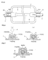
- [Fig. 1] is an explanatory view showing an example of a shaft-member holding construction according to the present invention,
- [Fig. 2] is an explanatory view showing manners of movements of a shaft member and a rotary member,
- [Fig. 3] is an exploded perspective view showing a manner of assembly of the shaft member and the rotary member,
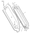
- [Fig. 4] is a perspective view showing an assembled condition of the shaft member and the rotary member,
- [Fig. 5] is a section view showing an attachment condition of the shaft member in details,
- [Fig. 6] is an explanatory view showing a manner of attachment of the shaft member to a bearing holding member,
- [Fig. 7] is a section view showing an embodiment including an external force applying member, and
- [Fig. 8] is a section view showing an embodiment including a chamfered portion.
-
- 2
- rotary member
- 4
- shaft member
- 4a
- chamfered portion
- 5
- bearing
- 8c
- wall portion
- 11
- gap closing member
- 12
- external force applying member
- 31
- first bearing holding member (bearing holding member)
- 31 a
- first opening (opening)
- 31b
- gap
- 32
- second bearing holding member (bearing holding member)
- 32a
- second opening (opening)
- 32b
- gap
Claims (9)
- A shaft-member holding construction comprising:a shaft member supporting a rotary member;a bearing for rotatably holding said shaft member; anda bearing holding member having an opening capable of receiving said bearing along an axial direction of said shaft member, said bearing holding member having a gap capable of receiving said shaft member from a radial direction relative to said axial direction.
- The shaft-member holding construction according to claim 1, wherein said shaft member includes a chamfered portion at a portion thereof to be received by said bearing holding member.
- The shaft-member holding construction according to claim 1, wherein said gap is open on one side of the bearing holding member along the axial direction, and a wall portion is provided adjacent the other end of said gap opposite to said opening.
- The shaft-member holding construction according to claim 1, further comprising a gap closing member for closing said gap.
- The shaft-member holding construction according to claim 1, further comprising an external force applying member for coming into contact with the bearing holding member so as to prevent widening of said gap.
- The shaft-member holding construction according to claim 4, wherein said shaft-member holding construction is attached to an opening formed in a partitioning wall which divides an inner space of a surge tank constituting an intake apparatus, and said gap closing member is a concave portion provided in said partitioning wall for accommodating said bearing holding member therein when said holding construction is attached to said partitioning wall.
- The shaft-member holding construction according to claim 5, wherein said shaft-member holding construction is attached to an opening formed in a partitioning wall which divides an inner space of a surge tank constituting an intake apparatus, and said external force applying member is a concave portion provided in said partitioning wall for accommodating said bearing holding member therein when said holding construction is attached to said partitioning wall.
- A variable intake valve to be attached to an opening formed in an partitioning wall for dividing an inner space of a surge tank constituting an intake apparatus, the intake valve comprising:a valve body;a shaft member supporting said valve body;a bearing for rotatably holding said shaft member; anda bearing holding member having an opening capable of receiving said bearing along an axial direction of said shaft member,a gap provided in said bearing holding member, said gap being capable of receiving said shaft member from a radial direction relative to the axial direction; anda valve holder having a communication hole within which said valve is rotatable, said valve holder also having said bearing holding member, said valve holder being attached to said opening of the partitioning wall.
- An intake apparatus comprising:a surge tank;a partitioning wall for dividing an inner space of said surge tank into a first chamber and a second chamber;a first intake manifold communicated with said first chamber;a second intake manifold communicated with said second chamber; anda variable intake valve attached to an opening formed in said partitioning wall;
wherein said variable intake valve includes:a valve body;a shaft member supporting said valve body;a bearing for rotatably holding said shaft member; anda bearing holding member having an opening capable of receiving said bearing along an axial direction of said shaft member,a gap provided in said bearing holding member, said gap being capable of receiving said shaft member from a radial direction relative to the axial direction; anda valve holder having a communication hole within which said valve is rotatable, said valve holder also having said bearing holding member, said valve holder being attached to said opening of the partitioning wall.
Applications Claiming Priority (2)
| Application Number | Priority Date | Filing Date | Title |
|---|---|---|---|
| JP2005073389A JP2006258129A (en) | 2005-03-15 | 2005-03-15 | Shaft holding structure |
| PCT/JP2006/304457 WO2006098200A1 (en) | 2005-03-15 | 2006-03-08 | Shaft body holding structure, variable intake valve, and intake device |
Publications (1)
| Publication Number | Publication Date |
|---|---|
| EP1860339A1 true EP1860339A1 (en) | 2007-11-28 |
Family
ID=36991547
Family Applications (1)
| Application Number | Title | Priority Date | Filing Date |
|---|---|---|---|
| EP06715377A Withdrawn EP1860339A1 (en) | 2005-03-15 | 2006-03-08 | Shaft body holding structure, variable intake valve, and intake device |
Country Status (5)
| Country | Link |
|---|---|
| US (1) | US20080127928A1 (en) |
| EP (1) | EP1860339A1 (en) |
| JP (1) | JP2006258129A (en) |
| CN (1) | CN101142420A (en) |
| WO (1) | WO2006098200A1 (en) |
Cited By (1)
| Publication number | Priority date | Publication date | Assignee | Title |
|---|---|---|---|---|
| EP2728158A3 (en) * | 2012-11-01 | 2015-10-21 | Aisin Seiki Kabushiki Kaisha | Air intake control valve |
Families Citing this family (5)
| Publication number | Priority date | Publication date | Assignee | Title |
|---|---|---|---|---|
| US20100193594A1 (en) * | 2004-12-20 | 2010-08-05 | Edc Automotive, Llc | Electronic thermostat |
| JP4965513B2 (en) * | 2008-06-04 | 2012-07-04 | 愛三工業株式会社 | Intake manifold |
| JP5910614B2 (en) * | 2013-11-07 | 2016-04-27 | 株式会社デンソー | Intake control valve and its assembly method |
| CN105715367B (en) * | 2016-03-30 | 2018-08-17 | 吉林大学 | Based on can variable gas channel double fuel ignition internal combustion engine and control method |
| CN111059156A (en) * | 2019-12-25 | 2020-04-24 | 芜湖航瑞航空动力产业技术研究院有限公司 | Engine main bearing seat |
Family Cites Families (8)
| Publication number | Priority date | Publication date | Assignee | Title |
|---|---|---|---|---|
| JPS62100307U (en) * | 1985-12-14 | 1987-06-26 | ||
| JPH01108414A (en) * | 1987-10-22 | 1989-04-25 | Oki Electric Ind Co Ltd | Bearing holding method |
| US20030131818A1 (en) * | 2002-01-16 | 2003-07-17 | Kyle Gregoire | Intake manifold paddle system |
| JP4053393B2 (en) * | 2002-09-25 | 2008-02-27 | 愛三工業株式会社 | Intake control valve |
| DE10345105B4 (en) * | 2002-10-02 | 2015-02-19 | Siemens Vdo Automotive Inc. | Cone closure for laser welding seam on a component of an air intake |
| CA2470599C (en) * | 2003-06-13 | 2010-08-03 | Honda Motor Co., Ltd. | Dual port intake device for an internal combustion engine formed by injection molding |
| JP2005248987A (en) * | 2004-03-01 | 2005-09-15 | Denso Corp | Bearing support device |
| JP2006002601A (en) * | 2004-06-16 | 2006-01-05 | Mitsubishi Electric Corp | Intake manifold and manufacturing method thereof |
-
2005
- 2005-03-15 JP JP2005073389A patent/JP2006258129A/en not_active Withdrawn
-
2006
- 2006-03-08 EP EP06715377A patent/EP1860339A1/en not_active Withdrawn
- 2006-03-08 WO PCT/JP2006/304457 patent/WO2006098200A1/en not_active Ceased
- 2006-03-08 US US11/795,084 patent/US20080127928A1/en not_active Abandoned
- 2006-03-08 CN CNA2006800086133A patent/CN101142420A/en active Pending
Non-Patent Citations (1)
| Title |
|---|
| See references of WO2006098200A1 * |
Cited By (1)
| Publication number | Priority date | Publication date | Assignee | Title |
|---|---|---|---|---|
| EP2728158A3 (en) * | 2012-11-01 | 2015-10-21 | Aisin Seiki Kabushiki Kaisha | Air intake control valve |
Also Published As
| Publication number | Publication date |
|---|---|
| JP2006258129A (en) | 2006-09-28 |
| US20080127928A1 (en) | 2008-06-05 |
| CN101142420A (en) | 2008-03-12 |
| WO2006098200A1 (en) | 2006-09-21 |
Similar Documents
| Publication | Publication Date | Title |
|---|---|---|
| KR101570141B1 (en) | Bearing housing body group of an exhaust-gas turbocharger | |
| DE602004010346T2 (en) | Exhaust gas seal for a turbocharger | |
| EP2677126B1 (en) | Valve opening/closing timing control device | |
| US7162997B2 (en) | Flap arrangement in the flange area of an intake system for an internal combustion engine | |
| EP1860339A1 (en) | Shaft body holding structure, variable intake valve, and intake device | |
| EP2044302B1 (en) | Intake apparatus for internal combustion engine | |
| US20180283579A1 (en) | Variations of fluid opening geometry for rotary valve body | |
| JP4411767B2 (en) | Engine intake manifold | |
| KR102751267B1 (en) | Sealing member for a multi direction changeover valve and multi direction changeover valve including thereof | |
| US20080110430A1 (en) | Intake system of internal combustion engine | |
| US6237557B1 (en) | Integrated push rod locator in cylinder head gasket | |
| JP5910614B2 (en) | Intake control valve and its assembly method | |
| US8926439B2 (en) | Suction tube arrangement with improved actuating shaft | |
| US7699032B2 (en) | Camshaft of automotive combustion engines in particular | |
| US20180058399A1 (en) | Intake Device | |
| US20100108011A1 (en) | Intake device for internal combustion engines | |
| JP2019078333A (en) | Fluid control valve | |
| EP1983175A1 (en) | Rotary device and method for retaining a shaft within a housing of a rotary device | |
| EP3135896A1 (en) | Intake apparatus for internal combustion engine | |
| US20150300679A1 (en) | Flap device for an internal combustion engine or an electric vehicle | |
| US7373910B2 (en) | Arrangement for sealing a housing | |
| CN213581864U (en) | Pressure control device | |
| JP2006233806A (en) | Fuel delivery pipe | |
| JPH082449Y2 (en) | Piston insertion jig for integrated cylinder block | |
| JP4729396B2 (en) | Seal member mounting structure |
Legal Events
| Date | Code | Title | Description |
|---|---|---|---|
| PUAI | Public reference made under article 153(3) epc to a published international application that has entered the european phase |
Free format text: ORIGINAL CODE: 0009012 |
|
| 17P | Request for examination filed |
Effective date: 20070627 |
|
| AK | Designated contracting states |
Kind code of ref document: A1 Designated state(s): DE FR |
|
| DAX | Request for extension of the european patent (deleted) | ||
| RBV | Designated contracting states (corrected) |
Designated state(s): DE FR |
|
| STAA | Information on the status of an ep patent application or granted ep patent |
Free format text: STATUS: THE APPLICATION HAS BEEN WITHDRAWN |
|
| 18W | Application withdrawn |
Effective date: 20090709 |