EP1859996B1 - Transport vehicle equipped with access device for persons with reduced mobility - Google Patents
Transport vehicle equipped with access device for persons with reduced mobility Download PDFInfo
- Publication number
- EP1859996B1 EP1859996B1 EP07108716A EP07108716A EP1859996B1 EP 1859996 B1 EP1859996 B1 EP 1859996B1 EP 07108716 A EP07108716 A EP 07108716A EP 07108716 A EP07108716 A EP 07108716A EP 1859996 B1 EP1859996 B1 EP 1859996B1
- Authority
- EP
- European Patent Office
- Prior art keywords
- platform
- nose
- respect
- mobile platform
- mobile
- Prior art date
- Legal status (The legal status is an assumption and is not a legal conclusion. Google has not performed a legal analysis and makes no representation as to the accuracy of the status listed.)
- Not-in-force
Links
Images


Classifications
-
- B—PERFORMING OPERATIONS; TRANSPORTING
- B61—RAILWAYS
- B61D—BODY DETAILS OR KINDS OF RAILWAY VEHICLES
- B61D23/00—Construction of steps for railway vehicles
- B61D23/02—Folding steps for railway vehicles, e.g. hand or mechanically actuated
- B61D23/025—Folding steps for railway vehicles, e.g. hand or mechanically actuated electrically or fluid actuated
-
- A—HUMAN NECESSITIES
- A61—MEDICAL OR VETERINARY SCIENCE; HYGIENE
- A61G—TRANSPORT, PERSONAL CONVEYANCES OR ACCOMMODATION SPECIALLY ADAPTED FOR PATIENTS OR DISABLED PERSONS; OPERATING TABLES OR CHAIRS; CHAIRS FOR DENTISTRY; FUNERAL DEVICES
- A61G3/00—Ambulance aspects of vehicles; Vehicles with special provisions for transporting patients or disabled persons, or their personal conveyances, e.g. for facilitating access of, or for loading, wheelchairs
- A61G3/02—Loading or unloading personal conveyances; Facilitating access of patients or disabled persons to, or exit from, vehicles
- A61G3/06—Transfer using ramps, lifts or the like
- A61G3/061—Transfer using ramps, lifts or the like using ramps
-
- A—HUMAN NECESSITIES
- A61—MEDICAL OR VETERINARY SCIENCE; HYGIENE
- A61G—TRANSPORT, PERSONAL CONVEYANCES OR ACCOMMODATION SPECIALLY ADAPTED FOR PATIENTS OR DISABLED PERSONS; OPERATING TABLES OR CHAIRS; CHAIRS FOR DENTISTRY; FUNERAL DEVICES
- A61G3/00—Ambulance aspects of vehicles; Vehicles with special provisions for transporting patients or disabled persons, or their personal conveyances, e.g. for facilitating access of, or for loading, wheelchairs
- A61G3/02—Loading or unloading personal conveyances; Facilitating access of patients or disabled persons to, or exit from, vehicles
- A61G3/06—Transfer using ramps, lifts or the like
- A61G3/067—Transfer using ramps, lifts or the like with compartment for horizontally storing the ramp or lift
-
- B—PERFORMING OPERATIONS; TRANSPORTING
- B60—VEHICLES IN GENERAL
- B60P—VEHICLES ADAPTED FOR LOAD TRANSPORTATION OR TO TRANSPORT, TO CARRY, OR TO COMPRISE SPECIAL LOADS OR OBJECTS
- B60P1/00—Vehicles predominantly for transporting loads and modified to facilitate loading, consolidating the load, or unloading
- B60P1/43—Vehicles predominantly for transporting loads and modified to facilitate loading, consolidating the load, or unloading using a loading ramp mounted on the vehicle
- B60P1/431—Vehicles predominantly for transporting loads and modified to facilitate loading, consolidating the load, or unloading using a loading ramp mounted on the vehicle the ramp being stored under the loading floor when not in use
-
- B—PERFORMING OPERATIONS; TRANSPORTING
- B60—VEHICLES IN GENERAL
- B60R—VEHICLES, VEHICLE FITTINGS, OR VEHICLE PARTS, NOT OTHERWISE PROVIDED FOR
- B60R3/00—Arrangements of steps or ladders facilitating access to or on the vehicle, e.g. running-boards
- B60R3/02—Retractable steps or ladders, e.g. movable under shock
Definitions
- the present invention concerns a transport vehicle having devices of access for persons with reduced mobility.
- the invention is aimed at all types of transport vehicle whose route involves at least one station stop, during which people are likely to board the vehicle, and also to alight from it. It is aimed at such a vehicle, which may or may not be driven in a dedicated lane, in particular by means of electric wires, of rails or even by optical means.
- This type of transport vehicle typically includes a chassis mounted on at least one axle having bearing members, which are usually wheels with tyres.
- transport vehicles in the sense of the invention include in particular, but not exclusively, buses and also trolleybuses.
- this invention aims to improve the use of such a vehicle by persons with reduced mobility.
- the latter are notably persons who move around with the aid of a wheelchair.
- such persons with reduced mobility can access the vehicle by means of an access device which is mobile with respect to a platform fixed to the chassis of the vehicle.
- Said access device generally includes a ramp, lodged in its retracted position in a casing.
- the latter is arranged below the side edge of the fixed platform, said edge being adjacent to the vehicle's door.
- Said ramp may be opened out, when the vehicle is stopped, so that it comes to bear against the external platform next to the vehicle.
- said retractable ramp does not permit adaptation to different shapes of external platform, particularly when said external platforms have different heights.
- the ramp moves out in the direction of a middle area of the external platform, which is situated well below the upper surface of the external platform.
- said opened ramp does not guarantee the desired function, in that it is not suitable to ensure that persons with reduced mobility can access the interior of the vehicle.
- the invention aims to find a solution for the various disadvantages of the prior art as described above.
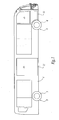
- the transport vehicle illustrated in figure 1 which is a bus or a tram, includes in a known manner a chassis 2, which is mounted on a front axle 4, as well as a rear axle 5. These two axles 4 and 5 are equipped with bearing members which are wheels on rubber tyres, numbered 6 and 7 respectively. Typically, it also has a front door 8, as well as a rear door 9.
- Two access devices 10 and 11, corresponding to this invention are included on the side of the vehicle, immediately below each door 8 and 9. Said access devices, which may be opened laterally, in other words perpendicularly to the surface of the page, shall be described in more detail below. Thus, in figure 1 , they are shown schematically.
- FIGS 2 to 5 show the chassis 2, illustrated in dashed font, the side edge of which has been numbered 2', as well as a fixed platform 12, extending approximately in parallel to the road, in other words usually in a horizontal direction.
- the access device 10, mentioned above, is formed by a mobile platform extending between a position alongside the side edge of the chassis 2 and the edge with respect to the fixed platform 12.
- Said mobile platform 10 is hinged, by any suitable means, such as a hinge which is shown schematically, with respect to the fixed platform 12.
- the hinge axis, marked A forms a longitudinal axis of the vehicle.
- the mobile platform 10 is equipped with a nose 16, mobile and travelling with respect to said platform 12 around an axis A', which is perpendicular to the aforesaid axis A.
- a nose 16 mobile and travelling with respect to said platform 12 around an axis A', which is perpendicular to the aforesaid axis A.
- devices, not illustrated which make it possible to move, on the one hand, the mobile platform with respect to the fixed platform and, on the other, the nose 16 with respect to the mobile platform 10.
- the nose 16 can be moved with respect to the mobile platform 10 by means of a cylinder, of a known variety.
- a sensor 18 is joined to the mobile platform 10, if necessary being fixed by any suitable means onto the lower surface of the latter. It could be an optical sensor, of the CCD variety, an ultrasound sensor, an inductive sensor or any other proximity detector of a known variety.
- the mobile platform 10 When in service, when the vehicle moves between two scheduled stops, the mobile platform 10 is in its position shown in figure 2A . This position is a raised one, since the angle formed between the two platforms 10 and 12 is small, for example in the region of 3%. Furthermore, the nose is retracted, so that the passengers can also stand on said mobile platform.
- the mobile platform 10 is thus secured and rotated with respect to the fixed platform 12. Then, the nose 16 is moved in a translatory movement according to arrow f 2 , until it comes to bear against the external platform 20, as illustrated in figure 2C . In these conditions, persons with reduced mobility are then likely to move, from the external platform 20, along the mobile platform 10, in the direction of the fixed platform 12 on the chassis.
- the movement of the nose with respect to the mobile platform is operated after the mobile platform has pivoted around the fixed platform.
- the nose can be moved before the pivoting phase of the mobile platform, or at the same time as it.
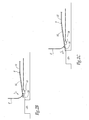
- FIGS 3A to 3C illustrate a further embodiment of the invention.
- the mechanical elements that are the same as in 2A to 2C are given the same reference numbers, increased by 100.
- the nose 116 is put into motion by a cylinder 122, the body 122 1 of which is hinged with respect to the mobile platform 110, around an axis A 1 .
- Said body 122 1 is joined to a cylinder rod 122 2 , joined in a translatory movement to the nose 116 while also being hinged to it around a second axis marked A 2 .
- the nose 116 is hinged, at the level of middle area, to the mobile platform 110, around a third axis, marked A 3 . It should be noted that these three axes, A 1 to A 3 , are approximately parallel to each other. Furthermore, the nose 116 is mounted on the lower surface of the mobile platform 110.
- Figure 3A again illustrates the retracted position of the mobile platform 110, which corresponds to the layout of figure 2A .
- the setting in motion, on the one hand, of the mobile platform 110 with respect to the fixed platform 112 and, on the other, of the nose 116 with respect to the mobile platform 110 operates in a similar way to that described above with reference to the first embodiment.
- it is necessary to move in a translatory movement the nose 116 with respect to the mobile platform 110 it is necessary to extend the cylinder rod 122 2 with respect to the body 122 1 of the cylinder.
- Said wheel 200 then exerts a force, marked F 1 , which is directed approximately downwards and does not therefore cause any rotation of the nose 116 with respect to the platform 110.
- F 1 a force which is directed approximately downwards and does not therefore cause any rotation of the nose 116 with respect to the platform 110.
- the nose 116 is arranged on the lower surface of said platform 110 so that it prevents the aforementioned rotation from taking place.
- figure 3C illustrates a situation whereby the nose 116 meets an obstacle as it is moving, in particular the foot of a passenger which is marked 124.
- the contact of the nose 116 with said foot 124 exerts a force, marked F 2 , which is directed approximately upwards. This thus causes the nose 116 to rotate with respect to the mobile platform 110 around axis A 3 , according to arrow f'.
- F 2 a force
- a torsion spring could be used, in proximity to the first hinge axis A 1 . Said spring then helps to return the cylinder to its original position, according to arrow f".
- the invention allows the previously mentioned objectives to be achieved.
- the devices according to the invention allowing access for persons with reduced mobility, are extremely reliable.
- the invention makes use of a limited number of mechanical elements, which have a relatively simple structure.
- the access devices according to the invention are able to adapt to all kinds of external platforms, in particular those of different heights. Indeed, depending on the height of the external platform in question, it is possible to adjust the distance across which the mobile platform pivots.
Landscapes
- Public Health (AREA)
- Engineering & Computer Science (AREA)
- Health & Medical Sciences (AREA)
- Mechanical Engineering (AREA)
- Animal Behavior & Ethology (AREA)
- Life Sciences & Earth Sciences (AREA)
- General Health & Medical Sciences (AREA)
- Veterinary Medicine (AREA)
- Transportation (AREA)
- Vehicle Step Arrangements And Article Storage (AREA)
- Warehouses Or Storage Devices (AREA)
- Control Of Position, Course, Altitude, Or Attitude Of Moving Bodies (AREA)
- Vehicle Waterproofing, Decoration, And Sanitation Devices (AREA)
- Motorcycle And Bicycle Frame (AREA)
- Vehicle Body Suspensions (AREA)
Abstract
Description
- The present invention concerns a transport vehicle having devices of access for persons with reduced mobility.
- The invention is aimed at all types of transport vehicle whose route involves at least one station stop, during which people are likely to board the vehicle, and also to alight from it. It is aimed at such a vehicle, which may or may not be driven in a dedicated lane, in particular by means of electric wires, of rails or even by optical means.
- This type of transport vehicle typically includes a chassis mounted on at least one axle having bearing members, which are usually wheels with tyres. In these conditions, transport vehicles in the sense of the invention include in particular, but not exclusively, buses and also trolleybuses.
- More specifically, this invention aims to improve the use of such a vehicle by persons with reduced mobility. The latter are notably persons who move around with the aid of a wheelchair. In a known manner, such persons with reduced mobility can access the vehicle by means of an access device which is mobile with respect to a platform fixed to the chassis of the vehicle.
- Said access device generally includes a ramp, lodged in its retracted position in a casing. The latter is arranged below the side edge of the fixed platform, said edge being adjacent to the vehicle's door. Said ramp may be opened out, when the vehicle is stopped, so that it comes to bear against the external platform next to the vehicle.
- Such an access device is disclosed, for example, in German Utility model (Gebrauchsmuster)
DE 8910746 U1 , which represents the closest prior art for the present invention in that the features of the preamble of claim 1 are disclosed therein. - This known solution has certain disadvantages, however.
- Indeed, first of all it is not sufficiently reliable. In other words, when a stop is made, the operation consisting of opening out the aforesaid ramp can sometimes be critical, or even impossible to achieve.
- Furthermore, said retractable ramp does not permit adaptation to different shapes of external platform, particularly when said external platforms have different heights. Thus, when the external platform is relatively high, the ramp moves out in the direction of a middle area of the external platform, which is situated well below the upper surface of the external platform. In these conditions, said opened ramp does not guarantee the desired function, in that it is not suitable to ensure that persons with reduced mobility can access the interior of the vehicle.
- Finally, the operations to open out said ramp require significant monitoring on the part of the driver. This is therefore a disadvantage, particularly in that this manoeuvre causes a significant waste of time to the transport schedule.
- This having been specified, the invention aims to find a solution for the various disadvantages of the prior art as described above.
- To this end, it has as its object a transport vehicle, particularly a bus or a tram, including a chassis mounted on at least one axle joined to bearing members, such as wheels, the chassis having a fixed platform and at least one access device, mobile with respect to the fixed platform, the or each access device being movable between a retracted position and an open position, in which it allows persons with reduced mobility to access the fixed platform from a external platform, in particular persons who move around with the aid of a wheelchair, characterised in that said mobile access device is a mobile platform, allowing passengers to alight or descend in its retracted position, the or each mobile platform comprising a retractable nose, said retractable nose being able to be moved with respect to the mobile platform between a retracted position and an open position, in which it is able to come to bear against the external platform.
- According to other characteristics of the invention:
- the or each mobile platform is mounted so that it pivots with respect to the fixed platform;
- the or each mobile platform is mounted so that it pivots with respect to the fixed platform around a pivoting axis, forming a main longitudinal axis of the vehicle;
- there are means for detecting the presence of the external platform, joined to the mobile platform;
- the means of detection comprise a sensor, in particular of an optical, ultrasound or inductive type;
- the retractable nose is placed alongside the lower surface of the mobile platform and, in its opened position, said nose is hinged with respect to the mobile platform around a hinge axis, which is specifically parallel to a principal longitudinal axis of the vehicle;
- there is a displacement cylinder for the nose hinged with respect to the mobile platform, and the nose is hinged with respect to the cylinder rod around another hinge axis, which is specifically parallel to a principal longitudinal axis of the vehicle.
- The invention will be better understood and other advantages of said invention will become clearer in the light of the following description of a method of embodying a transport vehicle according to its principle, given purely by way of example and with reference to the annexed drawings, in which:
-
figure 1 is a side view, illustrating a transport vehicle according to the invention; -
figures 2A to 2C are rear views, illustrating an access device for persons with reduced mobility, which the vehicle infigure 1 is equipped with, in three different positions of its operation; and -
figures 3A to 3C are rear views, similar tofigures 2A to 2C , illustrating a further embodiment of the access device for persons with reduced mobility, in three phases of its operation. - The transport vehicle illustrated in
figure 1 , which is a bus or a tram, includes in a known manner achassis 2, which is mounted on a front axle 4, as well as arear axle 5. These twoaxles 4 and 5 are equipped with bearing members which are wheels on rubber tyres, numbered 6 and 7 respectively. Typically, it also has afront door 8, as well as arear door 9. - Two
access devices door figure 1 , they are shown schematically. -
Figures 2 to 5 illustrate, on a larger scale and from two different angles to that infigure 1 , theaccess device 10 which is connected to theforward door 8. However, theother access device 11 is in every way similar to that numbered 10 which shall now be described. -
Figures 2 to 5 show thechassis 2, illustrated in dashed font, the side edge of which has been numbered 2', as well as afixed platform 12, extending approximately in parallel to the road, in other words usually in a horizontal direction. Theaccess device 10, mentioned above, is formed by a mobile platform extending between a position alongside the side edge of thechassis 2 and the edge with respect to thefixed platform 12. Saidmobile platform 10 is hinged, by any suitable means, such as a hinge which is shown schematically, with respect to the fixedplatform 12. The hinge axis, marked A, forms a longitudinal axis of the vehicle. - Moreover, at its end opposite the
fixed platform 12, themobile platform 10 is equipped with anose 16, mobile and travelling with respect to saidplatform 12 around an axis A', which is perpendicular to the aforesaid axis A. there are also devices, not illustrated, which make it possible to move, on the one hand, the mobile platform with respect to the fixed platform and, on the other, thenose 16 with respect to themobile platform 10. - Therefore, in view of the downwards pivoting of the mobile platform, it is possible to make use of gravity, or of a suitable motor. A cam or motor could be used, so as to bring the pivoting mobile platform back up. Finally, the
nose 16 can be moved with respect to themobile platform 10 by means of a cylinder, of a known variety. - Lastly, a
sensor 18 is joined to themobile platform 10, if necessary being fixed by any suitable means onto the lower surface of the latter. It could be an optical sensor, of the CCD variety, an ultrasound sensor, an inductive sensor or any other proximity detector of a known variety. - When in service, when the vehicle moves between two scheduled stops, the
mobile platform 10 is in its position shown infigure 2A . This position is a raised one, since the angle formed between the twoplatforms - When the vehicle makes its stop, the
door 8 is opened in a known manner. If it is not necessary to provide access for any person with reduced mobility, themobile platform 10 is not moved. It can thus be used in the normal manner so that passengers can use it to move inside the vehicle. - On the other hand, if it is necessary to provide access for persons with reduced mobility, it is necessary to make the
mobile platform 10 pivot downwards following the arrow f1, until the beam 18' of thesensor 18 detects the proximity of theexternal platform 20. This intermediate position is illustrated infigure 2B . - The
mobile platform 10 is thus secured and rotated with respect to thefixed platform 12. Then, thenose 16 is moved in a translatory movement according to arrow f2, until it comes to bear against theexternal platform 20, as illustrated infigure 2C . In these conditions, persons with reduced mobility are then likely to move, from theexternal platform 20, along themobile platform 10, in the direction of thefixed platform 12 on the chassis. - Once the station stop is finished, it is necessary to retract the
nose 16, so that it no longer protrudes out over themobile platform 10. Finally, themobile platform 10 is once again pivoted upwards until it returns to its original position as infigure 2A . - In the example described above, the movement of the nose with respect to the mobile platform is operated after the mobile platform has pivoted around the fixed platform. However, as an alternative, the nose can be moved before the pivoting phase of the mobile platform, or at the same time as it.
-
Figures 3A to 3C illustrate a further embodiment of the invention. In these drawings, the mechanical elements that are the same as in 2A to 2C are given the same reference numbers, increased by 100. - In this alternative embodiment, the
nose 116 is put into motion by acylinder 122, thebody 1221 of which is hinged with respect to themobile platform 110, around an axis A1. Saidbody 1221 is joined to acylinder rod 1222, joined in a translatory movement to thenose 116 while also being hinged to it around a second axis marked A2. - Lastly, the
nose 116 is hinged, at the level of middle area, to themobile platform 110, around a third axis, marked A3. It should be noted that these three axes, A1 to A3, are approximately parallel to each other. Furthermore, thenose 116 is mounted on the lower surface of themobile platform 110. -
Figure 3A again illustrates the retracted position of themobile platform 110, which corresponds to the layout offigure 2A . The setting in motion, on the one hand, of themobile platform 110 with respect to the fixedplatform 112 and, on the other, of thenose 116 with respect to themobile platform 110, operates in a similar way to that described above with reference to the first embodiment. In particular, if it is necessary to move in a translatory movement thenose 116 with respect to themobile platform 110, it is necessary to extend thecylinder rod 1222 with respect to thebody 1221 of the cylinder. - Thus, as shown in
figure 3B , when thenose 116 comes to bear against the external platform, persons with reduced mobility are likely to move along themobile platform 110. In this respect, thewheel 200 of a wheelchair has been shown, allowing said persons to move. -
Said wheel 200 then exerts a force, marked F1, which is directed approximately downwards and does not therefore cause any rotation of thenose 116 with respect to theplatform 110. In particular this is due to the fact that thenose 116 is arranged on the lower surface of saidplatform 110 so that it prevents the aforementioned rotation from taking place. - In contrast,
figure 3C illustrates a situation whereby thenose 116 meets an obstacle as it is moving, in particular the foot of a passenger which is marked 124. The contact of thenose 116 with saidfoot 124 exerts a force, marked F2, which is directed approximately upwards. This thus causes thenose 116 to rotate with respect to themobile platform 110 around axis A3, according to arrow f'. In these conditions, it is assumed that any major constraint at the level of thefoot 124 is avoided, which is advantageous in terms of safety for the passengers. - The rotation of the nose is then accompanied by a movement of the
cylinder 122. In this respect, a torsion spring, not illustrated, could be used, in proximity to the first hinge axis A1. Said spring then helps to return the cylinder to its original position, according to arrow f". - The invention allows the previously mentioned objectives to be achieved.
- Thus, the devices according to the invention, allowing access for persons with reduced mobility, are extremely reliable. Indeed, the invention makes use of a limited number of mechanical elements, which have a relatively simple structure.
- Furthermore, it should be noted that the access devices according to the invention are able to adapt to all kinds of external platforms, in particular those of different heights. Indeed, depending on the height of the external platform in question, it is possible to adjust the distance across which the mobile platform pivots.
Claims (2)
- Transport vehicle, in particular a bus, trolleybus or tram, having a chassis (2) resting on bearing members, such as wheels (6, 7), the chassis (2) having a fixed platform (12; 112) and at least one access device (10, 11; 110) which is mobile with respect to the fixed platform, the or each access device being movable between a retracted and an open position, in which it allows persons with reduced mobility to access the fixed platform from an external platform (20; 120), in particular those persons travelling in a wheelchair, said mobile access device being a mobile platform (10, 11; 110) which also allows passengers to alight or descend when in its retracted position, the or each mobile platform (10, 11; 110) comprising a retractable nose (16; 116), said retractable nose (16; 116) being able to be moved with respect to the mobile platform between a retracted and an extended position, in which it is able to come to bear on the external platform (20; 120); said transport vehicle being characterized in that said retractable nose (116) is placed in proximity to the lower surface of said mobile platform (10,11;110) and, in its extended position, said nose (116) is hinged with respect to said mobile platform (110) around a hinge axis (A3), which specifically is parallel to a principal longitudinal axis of the vehicle; a cylinder (122) is adapted to move said hinged nose (116) with respect to the mobile platform (110).
- Transport vehicle according to claim 1, characterized in that said nose (116) is hinged with respect to the cylinder rod (1222) of said cylinder (122) around a further hinge axis (A2), which specifically is parallel to a principal longitudinal axis of the vehicle.
Applications Claiming Priority (1)
| Application Number | Priority Date | Filing Date | Title |
|---|---|---|---|
| FR0604604A FR2901515B1 (en) | 2006-05-23 | 2006-05-23 | TRANSPORT VEHICLE PROVIDED WITH ACCESS MEANS FOR PEOPLE WITH REDUCED MOBILITY |
Publications (2)
| Publication Number | Publication Date |
|---|---|
| EP1859996A1 EP1859996A1 (en) | 2007-11-28 |
| EP1859996B1 true EP1859996B1 (en) | 2010-04-07 |
Family
ID=36790956
Family Applications (1)
| Application Number | Title | Priority Date | Filing Date |
|---|---|---|---|
| EP07108716A Not-in-force EP1859996B1 (en) | 2006-05-23 | 2007-05-23 | Transport vehicle equipped with access device for persons with reduced mobility |
Country Status (5)
| Country | Link |
|---|---|
| EP (1) | EP1859996B1 (en) |
| AT (1) | ATE463389T1 (en) |
| DE (1) | DE602007005721D1 (en) |
| ES (1) | ES2343755T3 (en) |
| FR (1) | FR2901515B1 (en) |
Families Citing this family (5)
| Publication number | Priority date | Publication date | Assignee | Title |
|---|---|---|---|---|
| DE202008005490U1 (en) * | 2007-12-21 | 2009-04-30 | Gebr. Bode GmbH & Co. KG Fahrzeugtürsysteme | Sensing device for vehicle systems |
| ATE516003T1 (en) * | 2008-12-24 | 2011-07-15 | Iveco France Sa | TRANSPORT VEHICLE WITH ACCESS DEVICE FOR PEOPLE WITH LIMITED MOBILITY |
| FR2964918B1 (en) * | 2010-09-16 | 2013-02-08 | Sncf | DEVICE FOR ACCESSING A VEHICLE FROM A PLATFORM |
| AT515195B1 (en) * | 2014-04-07 | 2015-07-15 | Knorr Bremse Gmbh Division Ife Automatic Door Systems | Mobile footboard |
| WO2024229418A1 (en) * | 2023-05-03 | 2024-11-07 | Node Systems Inc. | Transfer ramp systems for loading, unloading, or transferring cargo between one or more commercial vehicles and associated systems, devices, and methods |
Family Cites Families (7)
| Publication number | Priority date | Publication date | Assignee | Title |
|---|---|---|---|---|
| DE3708498A1 (en) * | 1987-03-16 | 1988-09-29 | Dowaldwerke | Control for an extendable step for a railway carriage |
| GB2223211B (en) * | 1988-10-04 | 1992-10-28 | Youichi Tokunaga | Vehicle access safety device |
| DE8910746U1 (en) * | 1989-09-08 | 1989-10-19 | Karl Kässbohrer Fahrzeugwerke GmbH, 7900 Ulm | Boarding device for motor vehicles, in particular for buses |
| GB9818781D0 (en) * | 1998-08-28 | 1998-10-21 | Passenger Lift Serv Ltd | Access ramp |
| DE29820881U1 (en) * | 1998-11-23 | 1999-02-18 | IBEG Maschinen- und Gerätebau GmbH, 45770 Marl | Ascent and descent ramp (Senkrampe) for public transport |
| AT413519B (en) * | 2003-09-18 | 2006-03-15 | Knorr Bremse Gmbh | SLIDING KICK |
| GB2415179A (en) * | 2004-06-16 | 2005-12-21 | Glide Rite Products Ltd | Vehicle with movable floor and ramp |
-
2006
- 2006-05-23 FR FR0604604A patent/FR2901515B1/en not_active Expired - Fee Related
-
2007
- 2007-05-23 EP EP07108716A patent/EP1859996B1/en not_active Not-in-force
- 2007-05-23 DE DE602007005721T patent/DE602007005721D1/en active Active
- 2007-05-23 AT AT07108716T patent/ATE463389T1/en not_active IP Right Cessation
- 2007-05-23 ES ES07108716T patent/ES2343755T3/en active Active
Also Published As
| Publication number | Publication date |
|---|---|
| FR2901515A1 (en) | 2007-11-30 |
| EP1859996A1 (en) | 2007-11-28 |
| ES2343755T3 (en) | 2010-08-09 |
| ATE463389T1 (en) | 2010-04-15 |
| FR2901515B1 (en) | 2009-03-13 |
| DE602007005721D1 (en) | 2010-05-20 |
Similar Documents
| Publication | Publication Date | Title |
|---|---|---|
| CN100441457C (en) | sliding pedal | |
| US7793596B2 (en) | Retractable step | |
| EP2084046B1 (en) | Device for filling the gap between a platform and a railway vehicle | |
| KR101503063B1 (en) | Railway vehicle and device for accessing said vehicle | |
| CN121246738A (en) | Conveyor and automatic parking system for mobile four-wheeled vehicle | |
| CA2209087A1 (en) | An improved movable ramp assembly | |
| EP1859996A1 (en) | Transport vehicle equipped with access device for persons with reduced mobility | |
| US12577785B2 (en) | Ascending mechanised access ramp (A-MAR) | |
| KR20010022459A (en) | One-seat motor vehicle | |
| JP7773843B2 (en) | Work vehicles | |
| AU2017213560A1 (en) | Intelligent step for BRT platform | |
| JP2009132255A (en) | Boarding bridge, boarding bridge system, and mounting method of boarding bridge | |
| US20230293365A1 (en) | Descending mechanised access ramp (d-mar) | |
| EP1787613B1 (en) | Vehicle, device and process for accessing said vehicle by persons with reduced mobility | |
| JP2005119611A (en) | Getting-on/off step device for vehicle | |
| CN107472151A (en) | The electronic side of a kind of high intensity, self-locking type is stepped on and its method of work | |
| FR2632592B1 (en) | RETRACTABLE STEP-ATTACHMENT FOR A PASSENGER RAIL VEHICLE TRANSPORT VEHICLE | |
| JP3969568B2 (en) | Warning light lifting device | |
| EP3898375B1 (en) | Passenger transport vehicle | |
| EP1826063B1 (en) | Transport vehicle equipped with access device for persons with reduced mobility | |
| DE68901816D1 (en) | ENTRANCE ARRANGEMENT WITH RETRACTABLE STEPS FOR THE ENTRANCE AND EXIT CONTROL OF A RAILWAY VEHICLE FOR PASSENGER TRANSPORT. | |
| GB2417021A (en) | Passenger service vehicle disabled persons lift | |
| WO1999031324A1 (en) | Access platform for wheelchairs | |
| JP2002204814A (en) | Vehicle wheelchair lift device | |
| EP1787885B1 (en) | Transport vehicle having wheels with tyres |
Legal Events
| Date | Code | Title | Description |
|---|---|---|---|
| PUAI | Public reference made under article 153(3) epc to a published international application that has entered the european phase |
Free format text: ORIGINAL CODE: 0009012 |
|
| AK | Designated contracting states |
Kind code of ref document: A1 Designated state(s): AT BE BG CH CY CZ DE DK EE ES FI FR GB GR HU IE IS IT LI LT LU LV MC MT NL PL PT RO SE SI SK TR |
|
| AX | Request for extension of the european patent |
Extension state: AL BA HR MK YU |
|
| 17P | Request for examination filed |
Effective date: 20080527 |
|
| 17Q | First examination report despatched |
Effective date: 20080630 |
|
| AKX | Designation fees paid |
Designated state(s): AT BE BG CH CY CZ DE DK EE ES FI FR GB GR HU IE IS IT LI LT LU LV MC MT NL PL PT RO SE SI SK TR |
|
| GRAP | Despatch of communication of intention to grant a patent |
Free format text: ORIGINAL CODE: EPIDOSNIGR1 |
|
| GRAS | Grant fee paid |
Free format text: ORIGINAL CODE: EPIDOSNIGR3 |
|
| GRAA | (expected) grant |
Free format text: ORIGINAL CODE: 0009210 |
|
| AK | Designated contracting states |
Kind code of ref document: B1 Designated state(s): AT BE BG CH CY CZ DE DK EE ES FI FR GB GR HU IE IS IT LI LT LU LV MC MT NL PL PT RO SE SI SK TR |
|
| REG | Reference to a national code |
Ref country code: GB Ref legal event code: FG4D |
|
| REG | Reference to a national code |
Ref country code: CH Ref legal event code: EP |
|
| REG | Reference to a national code |
Ref country code: IE Ref legal event code: FG4D |
|
| REF | Corresponds to: |
Ref document number: 602007005721 Country of ref document: DE Date of ref document: 20100520 Kind code of ref document: P |
|
| REG | Reference to a national code |
Ref country code: NL Ref legal event code: T3 |
|
| REG | Reference to a national code |
Ref country code: SE Ref legal event code: TRGR |
|
| REG | Reference to a national code |
Ref country code: ES Ref legal event code: FG2A Ref document number: 2343755 Country of ref document: ES Kind code of ref document: T3 |
|
| PG25 | Lapsed in a contracting state [announced via postgrant information from national office to epo] |
Ref country code: SI Free format text: LAPSE BECAUSE OF FAILURE TO SUBMIT A TRANSLATION OF THE DESCRIPTION OR TO PAY THE FEE WITHIN THE PRESCRIBED TIME-LIMIT Effective date: 20100407 |
|
| LTIE | Lt: invalidation of european patent or patent extension |
Effective date: 20100407 |
|
| PG25 | Lapsed in a contracting state [announced via postgrant information from national office to epo] |
Ref country code: LT Free format text: LAPSE BECAUSE OF FAILURE TO SUBMIT A TRANSLATION OF THE DESCRIPTION OR TO PAY THE FEE WITHIN THE PRESCRIBED TIME-LIMIT Effective date: 20100407 |
|
| PG25 | Lapsed in a contracting state [announced via postgrant information from national office to epo] |
Ref country code: AT Free format text: LAPSE BECAUSE OF FAILURE TO SUBMIT A TRANSLATION OF THE DESCRIPTION OR TO PAY THE FEE WITHIN THE PRESCRIBED TIME-LIMIT Effective date: 20100407 Ref country code: FI Free format text: LAPSE BECAUSE OF FAILURE TO SUBMIT A TRANSLATION OF THE DESCRIPTION OR TO PAY THE FEE WITHIN THE PRESCRIBED TIME-LIMIT Effective date: 20100407 Ref country code: IS Free format text: LAPSE BECAUSE OF FAILURE TO SUBMIT A TRANSLATION OF THE DESCRIPTION OR TO PAY THE FEE WITHIN THE PRESCRIBED TIME-LIMIT Effective date: 20100807 Ref country code: LV Free format text: LAPSE BECAUSE OF FAILURE TO SUBMIT A TRANSLATION OF THE DESCRIPTION OR TO PAY THE FEE WITHIN THE PRESCRIBED TIME-LIMIT Effective date: 20100407 |
|
| PG25 | Lapsed in a contracting state [announced via postgrant information from national office to epo] |
Ref country code: CY Free format text: LAPSE BECAUSE OF FAILURE TO SUBMIT A TRANSLATION OF THE DESCRIPTION OR TO PAY THE FEE WITHIN THE PRESCRIBED TIME-LIMIT Effective date: 20100519 Ref country code: MC Free format text: LAPSE BECAUSE OF NON-PAYMENT OF DUE FEES Effective date: 20100531 Ref country code: PL Free format text: LAPSE BECAUSE OF FAILURE TO SUBMIT A TRANSLATION OF THE DESCRIPTION OR TO PAY THE FEE WITHIN THE PRESCRIBED TIME-LIMIT Effective date: 20100407 |
|
| PG25 | Lapsed in a contracting state [announced via postgrant information from national office to epo] |
Ref country code: GR Free format text: LAPSE BECAUSE OF FAILURE TO SUBMIT A TRANSLATION OF THE DESCRIPTION OR TO PAY THE FEE WITHIN THE PRESCRIBED TIME-LIMIT Effective date: 20100708 Ref country code: DK Free format text: LAPSE BECAUSE OF FAILURE TO SUBMIT A TRANSLATION OF THE DESCRIPTION OR TO PAY THE FEE WITHIN THE PRESCRIBED TIME-LIMIT Effective date: 20100407 Ref country code: EE Free format text: LAPSE BECAUSE OF FAILURE TO SUBMIT A TRANSLATION OF THE DESCRIPTION OR TO PAY THE FEE WITHIN THE PRESCRIBED TIME-LIMIT Effective date: 20100407 Ref country code: PT Free format text: LAPSE BECAUSE OF FAILURE TO SUBMIT A TRANSLATION OF THE DESCRIPTION OR TO PAY THE FEE WITHIN THE PRESCRIBED TIME-LIMIT Effective date: 20100809 |
|
| PLBE | No opposition filed within time limit |
Free format text: ORIGINAL CODE: 0009261 |
|
| STAA | Information on the status of an ep patent application or granted ep patent |
Free format text: STATUS: NO OPPOSITION FILED WITHIN TIME LIMIT |
|
| PG25 | Lapsed in a contracting state [announced via postgrant information from national office to epo] |
Ref country code: CZ Free format text: LAPSE BECAUSE OF FAILURE TO SUBMIT A TRANSLATION OF THE DESCRIPTION OR TO PAY THE FEE WITHIN THE PRESCRIBED TIME-LIMIT Effective date: 20100407 Ref country code: RO Free format text: LAPSE BECAUSE OF FAILURE TO SUBMIT A TRANSLATION OF THE DESCRIPTION OR TO PAY THE FEE WITHIN THE PRESCRIBED TIME-LIMIT Effective date: 20100407 Ref country code: SK Free format text: LAPSE BECAUSE OF FAILURE TO SUBMIT A TRANSLATION OF THE DESCRIPTION OR TO PAY THE FEE WITHIN THE PRESCRIBED TIME-LIMIT Effective date: 20100407 Ref country code: BE Free format text: LAPSE BECAUSE OF FAILURE TO SUBMIT A TRANSLATION OF THE DESCRIPTION OR TO PAY THE FEE WITHIN THE PRESCRIBED TIME-LIMIT Effective date: 20100407 |
|
| 26N | No opposition filed |
Effective date: 20110110 |
|
| PG25 | Lapsed in a contracting state [announced via postgrant information from national office to epo] |
Ref country code: IT Free format text: LAPSE BECAUSE OF NON-PAYMENT OF DUE FEES Effective date: 20100523 |
|
| PG25 | Lapsed in a contracting state [announced via postgrant information from national office to epo] |
Ref country code: IE Free format text: LAPSE BECAUSE OF NON-PAYMENT OF DUE FEES Effective date: 20100523 Ref country code: MT Free format text: LAPSE BECAUSE OF FAILURE TO SUBMIT A TRANSLATION OF THE DESCRIPTION OR TO PAY THE FEE WITHIN THE PRESCRIBED TIME-LIMIT Effective date: 20100407 |
|
| REG | Reference to a national code |
Ref country code: CH Ref legal event code: PL |
|
| PG25 | Lapsed in a contracting state [announced via postgrant information from national office to epo] |
Ref country code: CH Free format text: LAPSE BECAUSE OF NON-PAYMENT OF DUE FEES Effective date: 20110531 Ref country code: LI Free format text: LAPSE BECAUSE OF NON-PAYMENT OF DUE FEES Effective date: 20110531 |
|
| PG25 | Lapsed in a contracting state [announced via postgrant information from national office to epo] |
Ref country code: LU Free format text: LAPSE BECAUSE OF NON-PAYMENT OF DUE FEES Effective date: 20100523 Ref country code: BG Free format text: LAPSE BECAUSE OF FAILURE TO SUBMIT A TRANSLATION OF THE DESCRIPTION OR TO PAY THE FEE WITHIN THE PRESCRIBED TIME-LIMIT Effective date: 20100407 Ref country code: HU Free format text: LAPSE BECAUSE OF FAILURE TO SUBMIT A TRANSLATION OF THE DESCRIPTION OR TO PAY THE FEE WITHIN THE PRESCRIBED TIME-LIMIT Effective date: 20101008 |
|
| PG25 | Lapsed in a contracting state [announced via postgrant information from national office to epo] |
Ref country code: TR Free format text: LAPSE BECAUSE OF FAILURE TO SUBMIT A TRANSLATION OF THE DESCRIPTION OR TO PAY THE FEE WITHIN THE PRESCRIBED TIME-LIMIT Effective date: 20100407 |
|
| PG25 | Lapsed in a contracting state [announced via postgrant information from national office to epo] |
Ref country code: BG Free format text: LAPSE BECAUSE OF FAILURE TO SUBMIT A TRANSLATION OF THE DESCRIPTION OR TO PAY THE FEE WITHIN THE PRESCRIBED TIME-LIMIT Effective date: 20100707 |
|
| REG | Reference to a national code |
Ref country code: FR Ref legal event code: PLFP Year of fee payment: 10 |
|
| REG | Reference to a national code |
Ref country code: FR Ref legal event code: PLFP Year of fee payment: 11 |
|
| REG | Reference to a national code |
Ref country code: FR Ref legal event code: PLFP Year of fee payment: 12 |
|
| REG | Reference to a national code |
Ref country code: NL Ref legal event code: PD Owner name: IVECO FRANCE S.A.S.; FR Free format text: DETAILS ASSIGNMENT: CHANGE OF OWNER(S), CHANGE OF LEGAL ENTITY; FORMER OWNER NAME: IVECO FRANCE S.A. Effective date: 20230406 |
|
| PGFP | Annual fee paid to national office [announced via postgrant information from national office to epo] |
Ref country code: SE Payment date: 20230317 Year of fee payment: 17 |
|
| REG | Reference to a national code |
Ref country code: DE Ref legal event code: R081 Ref document number: 602007005721 Country of ref document: DE Owner name: IVECO FRANCE S.A.S., FR Free format text: FORMER OWNER: IVECO FRANCE S.A., VENISSIEUX, FR |
|
| P01 | Opt-out of the competence of the unified patent court (upc) registered |
Effective date: 20230522 |
|
| PGFP | Annual fee paid to national office [announced via postgrant information from national office to epo] |
Ref country code: NL Payment date: 20230525 Year of fee payment: 17 |
|
| REG | Reference to a national code |
Ref country code: ES Ref legal event code: PC2A Owner name: IVECO FRANCE S.A.S. Effective date: 20240614 |
|
| PGFP | Annual fee paid to national office [announced via postgrant information from national office to epo] |
Ref country code: GB Payment date: 20240521 Year of fee payment: 18 |
|
| PGFP | Annual fee paid to national office [announced via postgrant information from national office to epo] |
Ref country code: DE Payment date: 20240529 Year of fee payment: 18 |
|
| PGFP | Annual fee paid to national office [announced via postgrant information from national office to epo] |
Ref country code: ES Payment date: 20240610 Year of fee payment: 18 |
|
| PGFP | Annual fee paid to national office [announced via postgrant information from national office to epo] |
Ref country code: IT Payment date: 20240513 Year of fee payment: 18 Ref country code: FR Payment date: 20240527 Year of fee payment: 18 |
|
| REG | Reference to a national code |
Ref country code: SE Ref legal event code: EUG |
|
| REG | Reference to a national code |
Ref country code: NL Ref legal event code: MM Effective date: 20240601 |
|
| PG25 | Lapsed in a contracting state [announced via postgrant information from national office to epo] |
Ref country code: NL Free format text: LAPSE BECAUSE OF NON-PAYMENT OF DUE FEES Effective date: 20240601 |
|
| PG25 | Lapsed in a contracting state [announced via postgrant information from national office to epo] |
Ref country code: SE Free format text: LAPSE BECAUSE OF NON-PAYMENT OF DUE FEES Effective date: 20240524 |
|
| REG | Reference to a national code |
Ref country code: DE Ref legal event code: R119 Ref document number: 602007005721 Country of ref document: DE |
|
| GBPC | Gb: european patent ceased through non-payment of renewal fee |
Effective date: 20250523 |
|
| PG25 | Lapsed in a contracting state [announced via postgrant information from national office to epo] |
Ref country code: GB Free format text: LAPSE BECAUSE OF NON-PAYMENT OF DUE FEES Effective date: 20250523 |
|
| PG25 | Lapsed in a contracting state [announced via postgrant information from national office to epo] |
Ref country code: DE Free format text: LAPSE BECAUSE OF NON-PAYMENT OF DUE FEES Effective date: 20251202 |
|
| PG25 | Lapsed in a contracting state [announced via postgrant information from national office to epo] |
Ref country code: FR Free format text: LAPSE BECAUSE OF NON-PAYMENT OF DUE FEES Effective date: 20250531 |
|
| REG | Reference to a national code |
Ref country code: ES Ref legal event code: FD2A Effective date: 20260701 |
|
| PG25 | Lapsed in a contracting state [announced via postgrant information from national office to epo] |
Ref country code: ES Free format text: LAPSE BECAUSE OF NON-PAYMENT OF DUE FEES Effective date: 20250524 |