EP1859932A1 - Decorative sheet, formed product and transportation apparatus - Google Patents
Decorative sheet, formed product and transportation apparatus Download PDFInfo
- Publication number
- EP1859932A1 EP1859932A1 EP07010159A EP07010159A EP1859932A1 EP 1859932 A1 EP1859932 A1 EP 1859932A1 EP 07010159 A EP07010159 A EP 07010159A EP 07010159 A EP07010159 A EP 07010159A EP 1859932 A1 EP1859932 A1 EP 1859932A1
- Authority
- EP
- European Patent Office
- Prior art keywords
- decorative sheet
- protective layer
- formed product
- thickness
- base member
- Prior art date
- Legal status (The legal status is an assumption and is not a legal conclusion. Google has not performed a legal analysis and makes no representation as to the accuracy of the status listed.)
- Granted
Links
Images


Classifications
-
- B—PERFORMING OPERATIONS; TRANSPORTING
- B32—LAYERED PRODUCTS
- B32B—LAYERED PRODUCTS, i.e. PRODUCTS BUILT-UP OF STRATA OF FLAT OR NON-FLAT, e.g. CELLULAR OR HONEYCOMB, FORM
- B32B27/00—Layered products comprising a layer of synthetic resin
- B32B27/18—Layered products comprising a layer of synthetic resin characterised by the use of special additives
-
- B—PERFORMING OPERATIONS; TRANSPORTING
- B32—LAYERED PRODUCTS
- B32B—LAYERED PRODUCTS, i.e. PRODUCTS BUILT-UP OF STRATA OF FLAT OR NON-FLAT, e.g. CELLULAR OR HONEYCOMB, FORM
- B32B27/00—Layered products comprising a layer of synthetic resin
- B32B27/06—Layered products comprising a layer of synthetic resin as the main or only constituent of a layer, which is next to another layer of the same or of a different material
- B32B27/08—Layered products comprising a layer of synthetic resin as the main or only constituent of a layer, which is next to another layer of the same or of a different material of synthetic resin
-
- B—PERFORMING OPERATIONS; TRANSPORTING
- B32—LAYERED PRODUCTS
- B32B—LAYERED PRODUCTS, i.e. PRODUCTS BUILT-UP OF STRATA OF FLAT OR NON-FLAT, e.g. CELLULAR OR HONEYCOMB, FORM
- B32B27/00—Layered products comprising a layer of synthetic resin
- B32B27/30—Layered products comprising a layer of synthetic resin comprising vinyl (co)polymers; comprising acrylic (co)polymers
- B32B27/304—Layered products comprising a layer of synthetic resin comprising vinyl (co)polymers; comprising acrylic (co)polymers comprising vinyl halide (co)polymers, e.g. PVC, PVDC, PVF, PVDF
-
- B—PERFORMING OPERATIONS; TRANSPORTING
- B32—LAYERED PRODUCTS
- B32B—LAYERED PRODUCTS, i.e. PRODUCTS BUILT-UP OF STRATA OF FLAT OR NON-FLAT, e.g. CELLULAR OR HONEYCOMB, FORM
- B32B27/00—Layered products comprising a layer of synthetic resin
- B32B27/30—Layered products comprising a layer of synthetic resin comprising vinyl (co)polymers; comprising acrylic (co)polymers
- B32B27/308—Layered products comprising a layer of synthetic resin comprising vinyl (co)polymers; comprising acrylic (co)polymers comprising acrylic (co)polymers
-
- B—PERFORMING OPERATIONS; TRANSPORTING
- B32—LAYERED PRODUCTS
- B32B—LAYERED PRODUCTS, i.e. PRODUCTS BUILT-UP OF STRATA OF FLAT OR NON-FLAT, e.g. CELLULAR OR HONEYCOMB, FORM
- B32B27/00—Layered products comprising a layer of synthetic resin
- B32B27/36—Layered products comprising a layer of synthetic resin comprising polyesters
- B32B27/365—Layered products comprising a layer of synthetic resin comprising polyesters comprising polycarbonates
-
- B—PERFORMING OPERATIONS; TRANSPORTING
- B60—VEHICLES IN GENERAL
- B60R—VEHICLES, VEHICLE FITTINGS, OR VEHICLE PARTS, NOT OTHERWISE PROVIDED FOR
- B60R13/00—Elements for body-finishing, identifying, or decorating; Arrangements or adaptations for advertising purposes
- B60R13/04—External Ornamental or guard strips; Ornamental inscriptive devices thereon
-
- B—PERFORMING OPERATIONS; TRANSPORTING
- B32—LAYERED PRODUCTS
- B32B—LAYERED PRODUCTS, i.e. PRODUCTS BUILT-UP OF STRATA OF FLAT OR NON-FLAT, e.g. CELLULAR OR HONEYCOMB, FORM
- B32B2307/00—Properties of the layers or laminate
- B32B2307/40—Properties of the layers or laminate having particular optical properties
- B32B2307/402—Coloured
-
- B—PERFORMING OPERATIONS; TRANSPORTING
- B32—LAYERED PRODUCTS
- B32B—LAYERED PRODUCTS, i.e. PRODUCTS BUILT-UP OF STRATA OF FLAT OR NON-FLAT, e.g. CELLULAR OR HONEYCOMB, FORM
- B32B2307/00—Properties of the layers or laminate
- B32B2307/40—Properties of the layers or laminate having particular optical properties
- B32B2307/402—Coloured
- B32B2307/4023—Coloured on the layer surface, e.g. ink
-
- B—PERFORMING OPERATIONS; TRANSPORTING
- B32—LAYERED PRODUCTS
- B32B—LAYERED PRODUCTS, i.e. PRODUCTS BUILT-UP OF STRATA OF FLAT OR NON-FLAT, e.g. CELLULAR OR HONEYCOMB, FORM
- B32B2307/00—Properties of the layers or laminate
- B32B2307/40—Properties of the layers or laminate having particular optical properties
- B32B2307/402—Coloured
- B32B2307/4026—Coloured within the layer by addition of a colorant, e.g. pigments, dyes
-
- B—PERFORMING OPERATIONS; TRANSPORTING
- B32—LAYERED PRODUCTS
- B32B—LAYERED PRODUCTS, i.e. PRODUCTS BUILT-UP OF STRATA OF FLAT OR NON-FLAT, e.g. CELLULAR OR HONEYCOMB, FORM
- B32B2307/00—Properties of the layers or laminate
- B32B2307/70—Other properties
- B32B2307/71—Resistive to light or to UV
-
- B—PERFORMING OPERATIONS; TRANSPORTING
- B32—LAYERED PRODUCTS
- B32B—LAYERED PRODUCTS, i.e. PRODUCTS BUILT-UP OF STRATA OF FLAT OR NON-FLAT, e.g. CELLULAR OR HONEYCOMB, FORM
- B32B2307/00—Properties of the layers or laminate
- B32B2307/70—Other properties
- B32B2307/712—Weather resistant
-
- B—PERFORMING OPERATIONS; TRANSPORTING
- B32—LAYERED PRODUCTS
- B32B—LAYERED PRODUCTS, i.e. PRODUCTS BUILT-UP OF STRATA OF FLAT OR NON-FLAT, e.g. CELLULAR OR HONEYCOMB, FORM
- B32B2605/00—Vehicles
-
- Y—GENERAL TAGGING OF NEW TECHNOLOGICAL DEVELOPMENTS; GENERAL TAGGING OF CROSS-SECTIONAL TECHNOLOGIES SPANNING OVER SEVERAL SECTIONS OF THE IPC; TECHNICAL SUBJECTS COVERED BY FORMER USPC CROSS-REFERENCE ART COLLECTIONS [XRACs] AND DIGESTS
- Y10—TECHNICAL SUBJECTS COVERED BY FORMER USPC
- Y10T—TECHNICAL SUBJECTS COVERED BY FORMER US CLASSIFICATION
- Y10T428/00—Stock material or miscellaneous articles
- Y10T428/24—Structurally defined web or sheet [e.g., overall dimension, etc.]
- Y10T428/2419—Fold at edge
- Y10T428/24215—Acute or reverse fold of exterior component
-
- Y—GENERAL TAGGING OF NEW TECHNOLOGICAL DEVELOPMENTS; GENERAL TAGGING OF CROSS-SECTIONAL TECHNOLOGIES SPANNING OVER SEVERAL SECTIONS OF THE IPC; TECHNICAL SUBJECTS COVERED BY FORMER USPC CROSS-REFERENCE ART COLLECTIONS [XRACs] AND DIGESTS
- Y10—TECHNICAL SUBJECTS COVERED BY FORMER USPC
- Y10T—TECHNICAL SUBJECTS COVERED BY FORMER US CLASSIFICATION
- Y10T428/00—Stock material or miscellaneous articles
- Y10T428/24—Structurally defined web or sheet [e.g., overall dimension, etc.]
- Y10T428/2419—Fold at edge
- Y10T428/24215—Acute or reverse fold of exterior component
- Y10T428/24231—At opposed marginal edges
-
- Y—GENERAL TAGGING OF NEW TECHNOLOGICAL DEVELOPMENTS; GENERAL TAGGING OF CROSS-SECTIONAL TECHNOLOGIES SPANNING OVER SEVERAL SECTIONS OF THE IPC; TECHNICAL SUBJECTS COVERED BY FORMER USPC CROSS-REFERENCE ART COLLECTIONS [XRACs] AND DIGESTS
- Y10—TECHNICAL SUBJECTS COVERED BY FORMER USPC
- Y10T—TECHNICAL SUBJECTS COVERED BY FORMER US CLASSIFICATION
- Y10T428/00—Stock material or miscellaneous articles
- Y10T428/24—Structurally defined web or sheet [e.g., overall dimension, etc.]
- Y10T428/24628—Nonplanar uniform thickness material
-
- Y—GENERAL TAGGING OF NEW TECHNOLOGICAL DEVELOPMENTS; GENERAL TAGGING OF CROSS-SECTIONAL TECHNOLOGIES SPANNING OVER SEVERAL SECTIONS OF THE IPC; TECHNICAL SUBJECTS COVERED BY FORMER USPC CROSS-REFERENCE ART COLLECTIONS [XRACs] AND DIGESTS
- Y10—TECHNICAL SUBJECTS COVERED BY FORMER USPC
- Y10T—TECHNICAL SUBJECTS COVERED BY FORMER US CLASSIFICATION
- Y10T428/00—Stock material or miscellaneous articles
- Y10T428/24—Structurally defined web or sheet [e.g., overall dimension, etc.]
- Y10T428/24802—Discontinuous or differential coating, impregnation or bond [e.g., artwork, printing, retouched photograph, etc.]
- Y10T428/24851—Intermediate layer is discontinuous or differential
- Y10T428/24868—Translucent outer layer
- Y10T428/24876—Intermediate layer contains particulate material [e.g., pigment, etc.]
-
- Y—GENERAL TAGGING OF NEW TECHNOLOGICAL DEVELOPMENTS; GENERAL TAGGING OF CROSS-SECTIONAL TECHNOLOGIES SPANNING OVER SEVERAL SECTIONS OF THE IPC; TECHNICAL SUBJECTS COVERED BY FORMER USPC CROSS-REFERENCE ART COLLECTIONS [XRACs] AND DIGESTS
- Y10—TECHNICAL SUBJECTS COVERED BY FORMER USPC
- Y10T—TECHNICAL SUBJECTS COVERED BY FORMER US CLASSIFICATION
- Y10T428/00—Stock material or miscellaneous articles
- Y10T428/24—Structurally defined web or sheet [e.g., overall dimension, etc.]
- Y10T428/24802—Discontinuous or differential coating, impregnation or bond [e.g., artwork, printing, retouched photograph, etc.]
- Y10T428/24893—Discontinuous or differential coating, impregnation or bond [e.g., artwork, printing, retouched photograph, etc.] including particulate material
- Y10T428/24901—Discontinuous or differential coating, impregnation or bond [e.g., artwork, printing, retouched photograph, etc.] including particulate material including coloring matter
-
- Y—GENERAL TAGGING OF NEW TECHNOLOGICAL DEVELOPMENTS; GENERAL TAGGING OF CROSS-SECTIONAL TECHNOLOGIES SPANNING OVER SEVERAL SECTIONS OF THE IPC; TECHNICAL SUBJECTS COVERED BY FORMER USPC CROSS-REFERENCE ART COLLECTIONS [XRACs] AND DIGESTS
- Y10—TECHNICAL SUBJECTS COVERED BY FORMER USPC
- Y10T—TECHNICAL SUBJECTS COVERED BY FORMER US CLASSIFICATION
- Y10T428/00—Stock material or miscellaneous articles
- Y10T428/24—Structurally defined web or sheet [e.g., overall dimension, etc.]
- Y10T428/24942—Structurally defined web or sheet [e.g., overall dimension, etc.] including components having same physical characteristic in differing degree
- Y10T428/2495—Thickness [relative or absolute]
- Y10T428/24967—Absolute thicknesses specified
Definitions
- the present invention relates to a decorative sheet to be stretched and attached onto the surface of an object, and also relates to a formed product and a transportation apparatus decorated with such a decorative sheet.
- a painted exterior member should have weather resistance and damage resistance that are high enough for the product to withstand long-term usage outdoors.
- top coating To provide sufficient weather resistance and damage resistance to an exterior member, a "top coating” technique is often adopted in the field of car painting. According to the top coating technique, the uppermost surface of a painted exterior member is coated with an acrylic resin or a fluorine resin, for example, thereby increasing its weather resistance and damage resistance.
- FIG. 9 shows an example of the decorative sheet.
- the decorative sheet 110 shown in FIG. 9 includes a base member 1 of a resin material and a decoration layer 2 formed on the principal surface 1 of the base member 1 by printing a pattern on that surface 1a with ink, for example.
- a formed product 120 with a decorated surface can be obtained.
- the formed product 121 shown in FIG. 10A includes a hemispherical (cuplike) raised portion 121a and therefore has a rugged surface. For that reason, the decorative sheet 110 being attached is stretched so as to follow such ruggedness perfectly. To stretch the decorative sheet 110 just as intended, the decorative sheet 110 is typically heated and softened before being attached.
- a formed product with a decorative sheet can be recycled more easily than a formed product with a painted surface.
- a decorated product can have a different type of fine appearance from that of a painted product. That is why a decorative sheet contributes to improving the appearance of formed products noticeably. For these reasons, a method using a decorative sheet is very useful.
- Japanese Laid-Open Patent Publication No. 2004-250581 discloses a stack of resin layers with good weather resistance.
- FIG. 11 illustrates such a stack 210 of resin layers.
- the stack 210 of resin layers includes a base member 211 made of polycarbonate, an acrylic resin layer 212 with a UV absorbent material, and a cured layer 213 formed by curing a coating agent in which a number of ingredients are compounded so as to have a particular composition. These members and layers are stacked in this order one upon the other.
- This stack 210 of resin layers realizes high weather resistance because the UV absorbent material included in the acrylic resin layer 212 absorbs UV rays.
- the overall decorative sheet may be thickened in advance because the decorative sheet is supposed to be stretched and have a reduced thickness eventually.
- the decorative sheet being attached to a formed product is not stretched uniformly everywhere. That is to say, the decorative sheet is stretched to different degrees from one portion of the sheet to another. For that reason, if the entire sheet were thickened, then a portion that would be thick enough even without being thickened that way should be too thick to avoid a significant increase in cost.
- the acrylic resin layer 212 including the UV absorbent material could be thickened. Actually, however, the acrylic resin layer 212 cannot be stretched so easily as the base member 211 of polycarbonate. That is why the thickened acrylic resin layer 212 could crack when stretched.
- the present invention increases the weather resistance of a decorative sheet that is supposed to be attached onto the surface of an object while being stretched and also prevents the sheet being attached from cracking.
- a decorative sheet according to a preferred embodiment of the present invention is attached to the surface of an object while being stretched.
- the decorative sheet preferably includes: a base member, which has first and second opposed principal surfaces; a protective layer, which is arranged over the first principal surface of the base member; and a coloring layer, which is arranged either over the second principal surface of the base member or between the base member and the protective layer and which includes a pigment.
- the protective layer preferably has a thickness of about 30 ⁇ m to about 60 ⁇ m and includes about 1.4 wt% to about 4.0 wt% of UV absorbent material.
- the coloring layer has a thickness of about 15 ⁇ m to about 80 ⁇ m and includes about 1.0 wt% to about 4.0 wt% of UV absorbent material.
- the base member preferably has a thickness of about 300 ⁇ m to about 800 ⁇ m.
- the pencil hardness of the protective layer at room temperature is higher than that of the base member.
- a formed product according to a preferred embodiment of the present invention includes a formed product body and a decorative sheet according to any of the preferred embodiments of the present invention described above that has been attached to a surface of the formed product body.
- the decorative sheet is bent over edges of the formed product body to reach the back surface of the formed product body.
- a portion of the decorative sheet is preferably about 30% to about 50% as thick as the thickest portion of the decorative sheet.
- a transportation apparatus includes a formed product according to any of the preferred embodiments described above.
- a UV absorbent material is included in both the protective layer and coloring layer thereof (i.e. , not just in the protective layer but also in the coloring layer), thus realizing high weather resistance easily.
- the protective layer preferably has a thickness of about 30 ⁇ m to about 60 ⁇ m and includes about 1.4 wt% to about 4.0 wt% of UV absorbent material, while the coloring layer has a thickness of about 15 ⁇ m to about 80 ⁇ m and includes about 1.0 wt% to about 4.0 wt% of UV absorbent material.
- the thicknesses and the contents of the UV absorbent material of both the protective layer and the coloring layer are defined within predetermined ranges. That is why even if the decorative sheet is attached onto the surface of an object while being stretched, sufficiently high weather resistance is realized and cracking can be avoided.
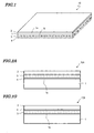
- FIG. 1 is a perspective view schematically illustrating a decorative sheet 10 according to a preferred embodiment of the present invention.
- FIGS. 2A and 2B are cross-sectional views schematically illustrating alternative decorative sheets 10A and 10B according to other preferred embodiments of the present invention.
- FIG. 3 schematically illustrates a vacuum forming system for use to decorate a formed product with the decorative sheet 10.
- FIGS. 4A and 4B are cross-sectional views schematically illustrating forming processing steps using the vacuum forming system shown in FIG. 3.
- FIGS. 5A and 5B are cross-sectional views schematically illustrating forming processing steps using the vacuum forming system shown in FIG. 3.
- FIGS. 6A, 6B and 6C are cross-sectional views schematically illustrating forming processing steps using the vacuum forming system shown in FIG. 3.
- FIG. 7 is a cross-sectional view illustrating an example of a formed product decorated with the decorative sheet 10.
- FIG. 8 is a side view schematically illustrating a motorcycle.
- FIG. 9 is a perspective view schematically illustrating a conventional decorative sheet 110 for use to decorate a formed product.
- FIGS. 10A, 10B and 10C schematically illustrate a process of decorating a formed product with a decorative sheet.
- FIG. 11 is a cross-sectional view schematically illustrating a stack 210 of resin layers including an acrylic resin layer with a UV absorbent material.
- FIG. 1 schematically illustrates a decorative sheet 10 according to a preferred embodiment of the present invention.
- the decorative sheet 10 is supposed to be attached onto the surface of an object while being stretched.
- the decorative sheet 10 includes a base member 1 with two opposed principal surfaces 1a and 1b, a protective layer 2 arranged over one principal surface 1a of the base member 1, and a coloring layer 3 arranged over the other principal surface 1b of the base member 1.
- the base member 1 is preferably made of a resin material and is typically made of a thermoplastic resin such as polycarbonate or vinyl chloride resin.
- the base member 1 should have some degree of rigidity that is high enough to serve as a sheet base member. That is why the material is preferably selected in view of this respect.
- the base member 1 preferably has a thickness of about 300 ⁇ m to about 800 ⁇ m. This is because if the base member 1 had a thickness of less than about 300 ⁇ m, the sheet would be difficult to handle or its mechanical strength could be too low to avoid tears when the sheet is being attached. On the other hand, if the thickness of the base member 1 exceeded about 800 ⁇ m, then the sheet could not fit closely the surface of the object to be decorated.
- the protective layer 2 is preferably made of a resin material.
- the pencil hardness of the protective layer 2 at room temperature is preferably higher than that of the base member 1.
- resin materials for the protective layer 2 include acrylic resins and vinyl chloride resins.
- acrylic resins including about 80 mol% or more of methyl methacrylate monomer derived repeating units and having a weight average molecular weight of approximately 70,000 to 150,000 can be used effectively.
- acrylic co-extruded polycarbonate DO-2 produced by Mitsubishi Gas Chemicals Co., Inc.
- DO-2 produced by Mitsubishi Gas Chemicals Co., Inc.
- the coloring layer 3 includes, and is colored by, a pigment.
- the coloring layer 3 may be formed by printing ink including a binder resin and the pigment dispersed in the binder resin.
- a binder resin an acrylic resin, a urethane resin, or an acrylic-urethane resin may be used, for example.
- the protective layer 2 and the coloring layer 3 both include a UV absorbent material, which may be a known one.
- the UV absorbent material included in the protective layer 2 may be TINUVIN 1577FF produced by Ciba Specialty Chemicals.
- the UV absorbent material included in the coloring layer 3 may be TINUVIN 328 or TINUVIN 571 also produced by Ciba Specialty Chemicals.
- the UV absorbent material included in the coloring layer 3 may be either solid at an ordinary temperature (as in TINUVIN 328 mentioned above) or liquid at an ordinary temperature (as in TINUVIN 571 mentioned above). If a liquid UV absorbent material is used, the coloring layer 3 will stretch more easily, and therefore is less likely to crack, than using a solid UV absorbent material. When a liquid UV absorbent material is used, however, that UV absorbent material might ooze out of the coloring layer 3 depending on its thickness.
- an adhesive 8 is applied onto the coloring layer 3 as indicated by the dotted line in FIG. 1.
- the adhesive a urethane or acrylic adhesive is preferably used.
- the decorative sheet 10 with such a structure may be used in a forming process as disclosed in Japanese Laid-Open Patent Publication No. 2005-153351 and can be used effectively to decorate a formed product with an extremely rugged surface.
- the decorative sheet 10 of this preferred embodiment includes a UV absorbent material in both of the protective layer 2 and the coloring layer 3 (i.e., not just in the protective layer 2 but also in the coloring layer 3), thus realizing high weather resistance relatively easily.
- a UV absorbent material in both of the protective layer 2 and the coloring layer 3 (i.e., not just in the protective layer 2 but also in the coloring layer 3), thus realizing high weather resistance relatively easily.
- the UV absorbent material is included in both the protective layer 2 and the coloring layer 3 as in this preferred embodiment, however, then a UV ray that has been transmitted through the protective layer 2 can be absorbed into the UV absorbent material included in the coloring layer 3. That is why it is possible to minimize the deterioration of the coloring layer 3 due to the repetitive exposure to the UV ray. As a result, the weather resistance of the decorative sheet 10 increases significantly.
- the thickness of the decorative sheet 10 may vary and part of the protective layer 2 may become too thin. If the protective layer 2 may become thin in certain areas in this manner or if the amount of the UV absorbent material included in the protective layer 2 is small, then many UV rays may transmit through the protective layer 2. However, if the UV absorbent material is included not just in the protective layer 2 but also in the coloring layer 3 as in this preferred embodiment, sufficiently high weather resistance is still guaranteed even when quite a few UV rays may transmit through the protective layer 2.
- the thicknesses and the UV absorbent material contents of both the protective layer 2 and the coloring layer 3 are defined within predetermined ranges. That is why even if the decorative sheet 10 is attached onto the surface of an object while being stretched, the decorative sheet 10 never cracks but realizes sufficiently high weather resistance.
- the protective layer 2 preferably has a thickness of about 30 ⁇ m to about 60 ⁇ m and preferably includes about 1.4 wt% to about 4.0 wt% of UV absorbent material.
- the coloring layer 3 preferably has a thickness of about 15 ⁇ m to about 80 ⁇ m and preferably includes about 1.0 wt% to about 4.0 wt% of UV absorbent material.
- the results are shown in the following Table 1.
- the thicknesses of the base members 1, protective layers 2 and coloring layers 3 shown in Table 1 were measured before and after stretching. Most of those decorative sheets 10 were rated in the three grades of "Good”, “Fair” and "Bad”.
- the weather resistance was estimated with a sunshine weatherometer compliant with the JIS B7753 standard.
- a decorative sheet 10 could maintain a color difference ⁇ E of 3 or less and at least 50% of the initial gloss for 600 hours or more, then the decorative sheet 10 was rated "Good”. If a decorative sheet 10 could maintain a color difference ⁇ E of 3 or less and at least 50% of the initial gloss for equal to or longer than 400 hours but less than 600 hours, then the decorative sheet 10 was rated "Fair”. And if a decorative sheet 10 could maintain a color difference ⁇ E of 3 or less and at least 50% of the initial gloss for less than 400 hours, then the decorative sheet 10 was rated "Bad". Oozing of the UV absorbent material was rated by observing the appearance of a decorative sheet 10 that was heated to 80 °C after having been stretched.
- Sample #5 including a protective layer 2 with a thickness of about 80 ⁇ m if the thickness of the protective layer 2 exceeded about 60 ⁇ m, the protective layer 2 cracked.
- Sample #1 including a protective layer 2 with a thickness of about 20 ⁇ m had no problem with its weather resistance, cracking and oozing but its overall rating is "Fair", not "Good”. This is because if the protective layer 2 were too thin (more specifically, had a thickness of less than about 30 ⁇ m), then the thickness of the protective layer 2 would vary significantly while the decorative sheet 10 is being made, thus making it difficult to form the sheet uniformly. The variation in the thickness of the protective layer 2 would cause a variation in the weather resistance of the decorative sheet.
- Sample #9 including a coloring layer 3 with a thickness of about 90 ⁇ m and Sample #10 including a coloring layer 3 with a thickness of about 100 ⁇ m if the thickness of the coloring layer 3 exceeded about 80 ⁇ m, the coloring layer 3 cracked.
- Sample #6 including a coloring layer 3 with a thickness of about 10 ⁇ m had no problem with its weather resistance, cracking and oozing but its overall rating is "Fair", not "Good”. This is because if the coloring layer 3 were too thin (more specifically, had a thickness of less than about 15 ⁇ m), then the thickness of the coloring layer 3 would vary significantly while the decorative sheet 10 is being made, thus producing color unevenness.
- Samples #2, #3, #4, #7 and #8 of which the protective layer 2 has a thickness of about 30 ⁇ m to about 60 ⁇ m and the coloring layer 3 has a thickness of about 15 ⁇ m to about 80 ⁇ m had no problem with its weather resistance, cracking and oozing.
- the variations in the thicknesses of the protective layer 2 and the coloring layer 3 while the sheet was being made were also small.
- the protective layer 2 preferably has a thickness of about 30 ⁇ m to about 60 ⁇ m and the coloring layer 3 preferably has a thickness of about 15 ⁇ m to about 80 ⁇ m.
- Tables 2, 3 and 4 shows the results in three different situations where the thicknesses of the base member 1 were changed into about 300 ⁇ m, about 500 ⁇ m and about 800 ⁇ m, respectively, with the thicknesses and the UV absorbent material contents of the protective coating 2 and the coloring layer 3 varied.
- Base member Protective layer Coloring layer Results of evaluations Thickness ratio before and after stretch Thickness ( ⁇ m) Thickness ( ⁇ m) UV absorbent content Thickness ( ⁇ m) UV absorbent content Weather resistance Protective layer cracked? Oozing Coloring layer cracked? Total Bfo. Aft. Bfo. Aft. Bfo. Aft.
- Base member Protective layer Coloring layer Results of evaluations Thickness ratio before and after stretch Thickness ( ⁇ m) Thickness ( ⁇ m) UV absorbent content Thickness ( ⁇ m) UV absorbent content Weather resistance Protective layer cracked? Oozing Coloring layer cracked? Total Bfo. Aft Bfo. Aft. Bfo. Aft.
- the protective layer 2 and the coloring layer 3 had their preferred minimum thicknesses of about 30 ⁇ m and about 15 ⁇ m and UV absorbent material contents of about 1.4 wt% and about 1.0 wt%, respectively (i.e., in Sample #18 shown in Table 2), sufficiently high weather resistance was realized.
- the protective layer 2 and the coloring layer 3 had thicknesses of about 30 ⁇ m and about 15 ⁇ m, respectively, and a UV absorbent material content of about 1.0 wt% (not shown in any of these tables), the resultant weather resistance was not enough.
- the protective layer 2 or the coloring layer 3 included no UV absorbent material at all (as in Samples #14, #15, #16 and #17), the resultant weather resistance was not enough, either.
- the protective layer 2 and the coloring layer 3 had their preferred maximum thicknesses of about 60 ⁇ m and about 80 ⁇ m, respectively, and a UV absorbent material content of about 4.0 wt% (i.e., in Sample #19 shown in Table 2), neither the protective layer 2 nor the coloring layer 3 cracked and good formability was realized.
- the protective layer 2 had a thickness of about 60 ⁇ m and a UV absorbent material content of about 5.0 wt% (as in Sample #15), the protective layer 2 cracked.
- the coloring layer 3 had a thickness of about 80 ⁇ m and a UV absorbent material content of about 5.0 wt% (as in Sample #17), the coloring layer 3 cracked, too.
- the protective layer 2 preferably has a UV absorbent material content of about 1.4 wt% to about 4.0 wt%
- the coloring layer 3 preferably has a UV absorbent material content of about 1.0 wt% to about 4.0 wt%.
- the protective layer 2 and the coloring layer 3 had a thickness of about 30 ⁇ m to about 60 ⁇ m and a thickness of about 15 ⁇ m to about 80 ⁇ m, respectively, and also had UV absorbent material contents falling within the ranges defined above (as in Samples #12, #18, #19, #20 and #21), good results of evaluation were achieved.
- the thickness and UV absorbent material content of the protective layer 2 within the range of about 30 ⁇ m to about 60 ⁇ m and within the range of about 1.4 wt% to about 4.0 wt% and by setting the thickness and UV absorbent material content of the coloring layer 3 within the range of about 15 ⁇ m to about 80 ⁇ m and within the range of about 1.0 wt% to about 4.0 wt%, it is possible to prevent the decorative sheet 10 from cracking and sufficiently high weather resistance is realized.
- FIG. 1 a structure in which the protective layer 2 is arranged on one side of the base member 1 and the coloring layer 3 on the other side of the base member 1 is illustrated.
- the coloring layer 3 does not always have to be arranged that way.
- the coloring layer 3 may also be located between the base member 1 and the protective layer 2.
- an adhesive layer 4, the coloring layer 3 and the protective layer 2 are stacked in this order on the principal surface 1a of the base member 1.
- the coloring layer 3, the adhesive layer 4, and the protective layer 2 are stacked in this order on the principal surface 1a of the base member 1.
- the decorative sheet 10A shown in FIG. 2A may be preferably made in the following manner, for example.
- a protective layer 2 is formed by an extrusion molding process.
- a coloring layer 3 is formed by a printing process on this protective layer 2.
- an adhesive layer 4 is applied onto either the coloring layer 3 or a base member 1 that has been formed separately by an extrusion molding process. Thereafter, the stack of the protective layer 2 and the coloring layer 3 and the base member 1 are bonded together with the adhesive layer 4, thereby obtaining the decorative sheet 10A.
- the decorative sheet 10B shown in FIG. 2B may be preferably made in the following manner, for example.
- a base member 1 is formed by an extrusion molding process.
- a coloring layer 3 is formed by a printing process on this base member 1.
- an adhesive layer 4 is applied onto either the coloring layer 3 or a protective layer 2 that has been formed separately by an extrusion molding process. Thereafter, the stack of the base member 1 and the coloring layer 3 and the protective layer 2 are bonded together with the adhesive layer 4, thereby obtaining the decorative sheet 10B.
- the adhesive layer 4 may be made of a known adhesive and may be formed by any of various known methods.
- the adhesive layer 4 may have a thickness of about 10 ⁇ m to about 60 ⁇ m, for example.
- FIG. 3 schematically illustrates a vacuum forming system 100 for use to decorate a formed product with the decorative sheet 10.
- FIGS. 4 through 6 are cross-sectional views schematically illustrating forming processing steps that use the vacuum forming system 100.
- the vacuum forming system 100 shown in FIG. 3 includes a gripping frame 30 to grip the decorative sheet 10 thereon, a supporting stage 31 for supporting a formed product thereon, a heater (such as a far-infrared heater) 33 for heating the decorative sheet 10, and a vacuum vessel 34 that stores all of these members.
- a gripping frame 30 to grip the decorative sheet 10 thereon
- a supporting stage 31 for supporting a formed product thereon
- a heater such as a far-infrared heater
- a vacuum vessel 34 that stores all of these members.
- the vacuum vessel 34 includes a main vessel 34a that stores the gripping frame 30 and the supporting stage 31, and a sub-vessel 34b that stores the heater 33. When the decorative sheet 10 is heated, the heater 33 is introduced into the main vessel 34a.
- the supporting stage 31 has a plurality of openings 31a, through which the air inside the main vessel 34a can be exhausted.
- a mechanism for introducing a gas from outside of this system into the main vessel 34a e.g., a hose connected to outside is also provided for the main vessel 34a.
- a formed product may be decorated with the decorative sheet 10 in the following manner, for example.
- a formed product body 21 is provided and mounted on the supporting stage 31.
- the formed product body 21 may be made of a resin material, a metallic material or any other suitable material by a known technique.
- the formed product body 21 may be made of a resin material by an injection molding process.
- the decorative sheet 10 includes a base member 1, and a protective layer 2 and a coloring layer 3, both of which include a UV absorbent material.
- the decorative sheet 10 is heated with the heater 33, thereby softening the decorative sheet 10.
- the decorative sheet 10 is preferably heated to a temperature that is approximately 20 °C to 30 °C higher than the lowest adhesion temperature of the adhesive 8 to ensure good adhesiveness for the adhesive 8.
- the decorative sheet 10 is brought down toward the formed product body 21 and then the pressure in the space 35 between the decorative sheet 10 and the formed product body 21 is reduced, thereby bonding the decorative sheet 10 onto the formed product body 21 as shown in FIG. 6A. If the pressure in the space 35 between the decorative sheet 10 and the formed product body 21 is reduced, then the decorative sheet 10 will be pressed against the formed product body 21 with uniform pressure. As a result, the sheet 10 can be bonded to the product 21 effectively.
- the space 36 over the decorative sheet 10 is also pressurized, thereby making an even bigger pressure difference. Consequently, the decorative sheet 10 can be bonded even more quickly.
- the pressure in the space 35 may be reduced by exhausting the air in the space 35 through the openings 31a of the supporting stage 31 using a vacuum pump, for example.
- the pressure in the space 36 may be increased by supplying compressed air thereto using a compressor, for example. In this bonding process step, the decorative sheet 10 is stretched and formed so as to fit the surface shape of the formed product 21 closely.
- an excessive portion 10' of the decorative sheet 10 is trimmed with a rotating blade or any other cutter, and then the formed product body 21 is removed from the supporting stage 31, thereby completing a formed product 20 with a decorated surface as shown in FIG. 6C.
- the decorative sheet 10 of this preferred embodiment it is possible to prevent the protective layer 2 and the coloring layer 3 from cracking while ensuring sufficiently high weather resistance and abrasion resistance. As a result, a formed product that can be used outdoors for a long time while maintaining its fine appearance is realized.
- FIG. 7 An example of a formed product 20 decorated with the decorative sheet 10 is shown in FIG. 7.
- the decorative sheet 10 has been attached so as to cover the edges of the formed product body 21 and reach the back surface 21a of the formed product body 21. In this manner, the decorative sheet 10 may be partially bent over around the edges of the formed product body 21.
- the thicknesses of the decorative sheet 10 that has been stretched and attached are shown in percentages with the thickest portion thereof identified by 100%. As shown in FIG. 7, the decorative sheet 10 decreases its thickness from the center of the formed product 20 toward the edges thereof, and gets thinnest at the bent portion.
- the weather resistance of the decorative sheet 10 becomes lowest at the thinnest portion. That is why sufficiently high weather resistance is preferably ensured even at the thinnest portion. For that reason, preferred embodiments of the present invention are effective particularly when a portion of the decorative sheet 10 is bent over around the edges of the formed product body 21 as shown in FIG. 7.
- preferred embodiments of the present invention are effective especially when the decorative sheet 10 has been stretched to a certain degree or more as a result of the forming process during the attachment. More specifically, preferred embodiments of the present invention are particularly applicable to a situation where the decorative sheet 10 attached includes a portion that is about 30% to about 50% as thick as the thickest portion thereof (e.g., the bent portion described above).
- a formed product decorated with the decorative sheet 10 of this preferred embodiment has such good weather resistance and such fine appearance that the product can be used effectively as an exterior member for various types of transportation apparatuses.
- the formed product can be used effectively as the tank housing 51, the front fender 52 or the tail cowl 53 of a motorcycle 50 as shown in FIG. 8.
- the weather resistance of a decorative sheet which should be attached onto the surface of a formed product while being stretched, can be increased sufficiently.
- a formed product decorated with the decorative sheet according to preferred embodiments of the present invention has such good weather resistance and such a fine appearance as to be used effectively as an exterior member for various types of transportation apparatuses including passenger cars, buses, trucks, motorcycles, tractors, airplanes, motorboats, and civil engineering vehicles.
Landscapes
- Engineering & Computer Science (AREA)
- Mechanical Engineering (AREA)
- Laminated Bodies (AREA)
- Decoration By Transfer Pictures (AREA)
Abstract
Description
- The present invention relates to a decorative sheet to be stretched and attached onto the surface of an object, and also relates to a formed product and a transportation apparatus decorated with such a decorative sheet.
- Various formed products are used as exterior members for a transportation apparatus such as a car. Those formed products have been decorated by painting in many cases. A painted exterior member should have weather resistance and damage resistance that are high enough for the product to withstand long-term usage outdoors.
- To provide sufficient weather resistance and damage resistance to an exterior member, a "top coating" technique is often adopted in the field of car painting. According to the top coating technique, the uppermost surface of a painted exterior member is coated with an acrylic resin or a fluorine resin, for example, thereby increasing its weather resistance and damage resistance.
- Meanwhile, it was recently proposed that a decorative sheet be attached to the surface of a formed product as a technique of decorating a formed product as disclosed in
Japanese Laid-Open Patent Publication No. 2005-1533511 - FIG. 9 shows an example of the decorative sheet. The
decorative sheet 110 shown in FIG. 9 includes abase member 1 of a resin material and adecoration layer 2 formed on theprincipal surface 1 of thebase member 1 by printing a pattern on thatsurface 1a with ink, for example. By attaching thisdecorative sheet 110 to the surface of thebody 121 of a formed product in the order shown in FIGS. 10A, 10B and 10C with an adhesive 8 applied on thedecoration layer 2, a formedproduct 120 with a decorated surface can be obtained. - The formed
product 121 shown in FIG. 10A includes a hemispherical (cuplike) raisedportion 121a and therefore has a rugged surface. For that reason, thedecorative sheet 110 being attached is stretched so as to follow such ruggedness perfectly. To stretch thedecorative sheet 110 just as intended, thedecorative sheet 110 is typically heated and softened before being attached. - A formed product with a decorative sheet can be recycled more easily than a formed product with a painted surface. In addition, a decorated product can have a different type of fine appearance from that of a painted product. That is why a decorative sheet contributes to improving the appearance of formed products noticeably. For these reasons, a method using a decorative sheet is very useful.
- If a decorative sheet is used to decorate an exterior member, however, the ink contained in the decoration layer might be deteriorated by UV rays included in sunlight. For that reason, the weather resistance of a decorative sheet needs to be increased.
-
Japanese Laid-Open Patent Publication No. 2004-250581 stack 210 of resin layers. - As shown in FIG. 11, the
stack 210 of resin layers includes abase member 211 made of polycarbonate, anacrylic resin layer 212 with a UV absorbent material, and a curedlayer 213 formed by curing a coating agent in which a number of ingredients are compounded so as to have a particular composition. These members and layers are stacked in this order one upon the other. - This
stack 210 of resin layers realizes high weather resistance because the UV absorbent material included in theacrylic resin layer 212 absorbs UV rays. - However, the present inventors discovered and confirmed via experiments that even when a
stack 210 of resin layers as disclosed in Japanese Laid-Open Patent PublicationNo. 2004-250581 Japanese Laid-Open Patent Publication No. 2005-153351 acrylic resin layer 212 has a reduced thickness, then the amount of the UV absorbent material contained per unit area of the decorative sheet decreases. As a result, UV rays cannot be absorbed sufficiently and the weather resistance decreases. - To overcome such a problem, the overall decorative sheet may be thickened in advance because the decorative sheet is supposed to be stretched and have a reduced thickness eventually. However, the decorative sheet being attached to a formed product is not stretched uniformly everywhere. That is to say, the decorative sheet is stretched to different degrees from one portion of the sheet to another. For that reason, if the entire sheet were thickened, then a portion that would be thick enough even without being thickened that way should be too thick to avoid a significant increase in cost.
- Only the
acrylic resin layer 212 including the UV absorbent material could be thickened. Actually, however, theacrylic resin layer 212 cannot be stretched so easily as thebase member 211 of polycarbonate. That is why the thickenedacrylic resin layer 212 could crack when stretched. - In order to overcome the problems described above, the present invention increases the weather resistance of a decorative sheet that is supposed to be attached onto the surface of an object while being stretched and also prevents the sheet being attached from cracking.
- A decorative sheet according to a preferred embodiment of the present invention is attached to the surface of an object while being stretched. The decorative sheet preferably includes: a base member, which has first and second opposed principal surfaces; a protective layer, which is arranged over the first principal surface of the base member; and a coloring layer, which is arranged either over the second principal surface of the base member or between the base member and the protective layer and which includes a pigment. The protective layer preferably has a thickness of about 30 µm to about 60 µm and includes about 1.4 wt% to about 4.0 wt% of UV absorbent material. And the coloring layer has a thickness of about 15 µm to about 80 µm and includes about 1.0 wt% to about 4.0 wt% of UV absorbent material.
- In one preferred embodiment, the base member preferably has a thickness of about 300 µm to about 800 µm.
- In another preferred embodiment, the pencil hardness of the protective layer at room temperature is higher than that of the base member.
- A formed product according to a preferred embodiment of the present invention includes a formed product body and a decorative sheet according to any of the preferred embodiments of the present invention described above that has been attached to a surface of the formed product body.
- In one preferred embodiment, the decorative sheet is bent over edges of the formed product body to reach the back surface of the formed product body.
- In another preferred embodiment, a portion of the decorative sheet is preferably about 30% to about 50% as thick as the thickest portion of the decorative sheet.
- A transportation apparatus according to a preferred embodiment of the present invention includes a formed product according to any of the preferred embodiments described above.
- In a decorative sheet according to various preferred embodiments of the present invention, a UV absorbent material is included in both the protective layer and coloring layer thereof (i.e. , not just in the protective layer but also in the coloring layer), thus realizing high weather resistance easily.
- Also, in the decorative sheet of the present invention, the protective layer preferably has a thickness of about 30 µm to about 60 µm and includes about 1.4 wt% to about 4.0 wt% of UV absorbent material, while the coloring layer has a thickness of about 15 µm to about 80 µm and includes about 1.0 wt% to about 4.0 wt% of UV absorbent material. In this manner, the thicknesses and the contents of the UV absorbent material of both the protective layer and the coloring layer are defined within predetermined ranges. That is why even if the decorative sheet is attached onto the surface of an object while being stretched, sufficiently high weather resistance is realized and cracking can be avoided.
- Other features, elements, processes, steps, characteristics and advantages of the present invention will become more apparent from the following detailed description of preferred embodiments of the present invention with reference to the attached drawings.
- FIG. 1 is a perspective view schematically illustrating a
decorative sheet 10 according to a preferred embodiment of the present invention. - FIGS. 2A and 2B are cross-sectional views schematically illustrating alternative
decorative sheets - FIG. 3 schematically illustrates a vacuum forming system for use to decorate a formed product with the
decorative sheet 10. - FIGS. 4A and 4B are cross-sectional views schematically illustrating forming processing steps using the vacuum forming system shown in FIG. 3.
- FIGS. 5A and 5B are cross-sectional views schematically illustrating forming processing steps using the vacuum forming system shown in FIG. 3.
- FIGS. 6A, 6B and 6C are cross-sectional views schematically illustrating forming processing steps using the vacuum forming system shown in FIG. 3.
- FIG. 7 is a cross-sectional view illustrating an example of a formed product decorated with the
decorative sheet 10. - FIG. 8 is a side view schematically illustrating a motorcycle.
- FIG. 9 is a perspective view schematically illustrating a conventional
decorative sheet 110 for use to decorate a formed product. - FIGS. 10A, 10B and 10C schematically illustrate a process of decorating a formed product with a decorative sheet.
- FIG. 11 is a cross-sectional view schematically illustrating a
stack 210 of resin layers including an acrylic resin layer with a UV absorbent material. - Hereinafter, preferred embodiments of the present invention will be described with reference to the accompanying drawings. It should be noted, however, that the present invention is in no way limited to the following specific preferred embodiments.
- FIG. 1 schematically illustrates a
decorative sheet 10 according to a preferred embodiment of the present invention. Thedecorative sheet 10 is supposed to be attached onto the surface of an object while being stretched. - As shown in FIG. 1, the
decorative sheet 10 includes abase member 1 with two opposedprincipal surfaces protective layer 2 arranged over oneprincipal surface 1a of thebase member 1, and acoloring layer 3 arranged over the otherprincipal surface 1b of thebase member 1. - The
base member 1 is preferably made of a resin material and is typically made of a thermoplastic resin such as polycarbonate or vinyl chloride resin. Thebase member 1 should have some degree of rigidity that is high enough to serve as a sheet base member. That is why the material is preferably selected in view of this respect. Thebase member 1 preferably has a thickness of about 300 µm to about 800 µm. This is because if thebase member 1 had a thickness of less than about 300 µm, the sheet would be difficult to handle or its mechanical strength could be too low to avoid tears when the sheet is being attached. On the other hand, if the thickness of thebase member 1 exceeded about 800 µm, then the sheet could not fit closely the surface of the object to be decorated. - The
protective layer 2 is preferably made of a resin material. To increase the damage resistance of thedecorative sheet 10 to a sufficiently high level, the pencil hardness of theprotective layer 2 at room temperature is preferably higher than that of thebase member 1. Examples of resin materials for theprotective layer 2 include acrylic resins and vinyl chloride resins. For example, an acrylic resin including about 80 mol% or more of methyl methacrylate monomer derived repeating units and having a weight average molecular weight of approximately 70,000 to 150,000 can be used effectively. As abase member 1 with such aprotective layer 2, acrylic co-extruded polycarbonate DO-2 (produced by Mitsubishi Gas Chemicals Co., Inc.) may be used, for instance. - The
coloring layer 3 includes, and is colored by, a pigment. Thecoloring layer 3 may be formed by printing ink including a binder resin and the pigment dispersed in the binder resin. As the binder resin, an acrylic resin, a urethane resin, or an acrylic-urethane resin may be used, for example. - The
protective layer 2 and thecoloring layer 3 both include a UV absorbent material, which may be a known one. The UV absorbent material included in theprotective layer 2 may be TINUVIN 1577FF produced by Ciba Specialty Chemicals. On the other hand, the UV absorbent material included in thecoloring layer 3 may be TINUVIN 328 or TINUVIN 571 also produced by Ciba Specialty Chemicals. - Specifically, the UV absorbent material included in the
coloring layer 3 may be either solid at an ordinary temperature (as in TINUVIN 328 mentioned above) or liquid at an ordinary temperature (as in TINUVIN 571 mentioned above). If a liquid UV absorbent material is used, thecoloring layer 3 will stretch more easily, and therefore is less likely to crack, than using a solid UV absorbent material. When a liquid UV absorbent material is used, however, that UV absorbent material might ooze out of thecoloring layer 3 depending on its thickness. - When the
decorative sheet 10 is attached to a formed product, an adhesive 8 is applied onto thecoloring layer 3 as indicated by the dotted line in FIG. 1. As the adhesive, a urethane or acrylic adhesive is preferably used. - The
decorative sheet 10 with such a structure may be used in a forming process as disclosed inJapanese Laid-Open Patent Publication No. 2005-153351 - The
decorative sheet 10 of this preferred embodiment includes a UV absorbent material in both of theprotective layer 2 and the coloring layer 3 (i.e., not just in theprotective layer 2 but also in the coloring layer 3), thus realizing high weather resistance relatively easily. Hereinafter, the reasons will be described more specifically. - To prevent a UV ray from reaching the
coloring layer 3, it seems that a lot of UV absorbent material simply should be added only to theprotective layer 2. Actually, however, it is very difficult to absorb all UV rays (included in sunlight) impinging on thedecorative sheet 10 with only theprotective layer 2. That is why some of the UV rays that have been incident on thedecorative sheet 10 attached to an object are transmitted through theprotective layer 2 to reach thebase member 1 and thecoloring layer 3. After that, those UV rays are repeatedly reflected from the interface between thedecorative sheet 10 and the object, the interface between thebase member 1 and thecoloring layer 3, and the interface between thebase member 1 and theprotective layer 2. Consequently, part of a UV ray that has once been transmitted through thecoloring layer 3 may come back to thesame coloring layer 3 again. - If the UV absorbent material were included only in the
protective layer 2, a UV ray that has once been transmitted through theprotective layer 2 would never be absorbed into the UV absorbent material as long as the UV ray is repeatedly reflected from those interfaces. As a result, thecoloring layer 3 would be deteriorated by the UV ray. - If the UV absorbent material is included in both the
protective layer 2 and thecoloring layer 3 as in this preferred embodiment, however, then a UV ray that has been transmitted through theprotective layer 2 can be absorbed into the UV absorbent material included in thecoloring layer 3. That is why it is possible to minimize the deterioration of thecoloring layer 3 due to the repetitive exposure to the UV ray. As a result, the weather resistance of thedecorative sheet 10 increases significantly. - Also, when the
decorative sheet 10 is attached onto an object while being stretched, the thickness of thedecorative sheet 10 may vary and part of theprotective layer 2 may become too thin. If theprotective layer 2 may become thin in certain areas in this manner or if the amount of the UV absorbent material included in theprotective layer 2 is small, then many UV rays may transmit through theprotective layer 2. However, if the UV absorbent material is included not just in theprotective layer 2 but also in thecoloring layer 3 as in this preferred embodiment, sufficiently high weather resistance is still guaranteed even when quite a few UV rays may transmit through theprotective layer 2. - Furthermore, in the
decorative sheet 10 of this preferred embodiment, the thicknesses and the UV absorbent material contents of both theprotective layer 2 and thecoloring layer 3 are defined within predetermined ranges. That is why even if thedecorative sheet 10 is attached onto the surface of an object while being stretched, thedecorative sheet 10 never cracks but realizes sufficiently high weather resistance. - Specifically, the
protective layer 2 preferably has a thickness of about 30 µm to about 60 µm and preferably includes about 1.4 wt% to about 4.0 wt% of UV absorbent material. On the other hand, thecoloring layer 3 preferably has a thickness of about 15 µ m to about 80 µ m and preferably includes about 1.0 wt% to about 4.0 wt% of UV absorbent material. Hereinafter, it will be described why these ranges are preferred. - A number of
decorative sheets 10, includingprotective layers 2 of various thicknesses andcoloring layers 3 of various thicknesses, were provided, stretched to a predetermined thickness and then evaluated with respect to their weather resistance, cracking of theprotective layer 2, cracking of thecoloring layer 3 and oozing of the UV absorbent material out of thecoloring layer 3. The results are shown in the following Table 1. The thicknesses of thebase members 1,protective layers 2 andcoloring layers 3 shown in Table 1 were measured before and after stretching. Most of thosedecorative sheets 10 were rated in the three grades of "Good", "Fair" and "Bad". The weather resistance was estimated with a sunshine weatherometer compliant with the JIS B7753 standard. If adecorative sheet 10 could maintain a color difference ΔE of 3 or less and at least 50% of the initial gloss for 600 hours or more, then thedecorative sheet 10 was rated "Good". If adecorative sheet 10 could maintain a color difference ΔE of 3 or less and at least 50% of the initial gloss for equal to or longer than 400 hours but less than 600 hours, then thedecorative sheet 10 was rated "Fair". And if adecorative sheet 10 could maintain a color difference ΔE of 3 or less and at least 50% of the initial gloss for less than 400 hours, then thedecorative sheet 10 was rated "Bad". Oozing of the UV absorbent material was rated by observing the appearance of adecorative sheet 10 that was heated to 80 °C after having been stretched. This temperature was adopted because if thedecorative sheet 10 is used to decorate an exterior member of a motorcycle, then thedecorative sheet 10 would be heated to around 80 °C in sunshine.Table 1 No Base member Protective layer Coloring layer Results of evaluations Thickness ratio Before And after stretch Thickness (µm) Thickness (µm) UV absorbent content Thickness (µm) UV Absorbent content Weather resistance Protective layer cracked? Oozing Coloring layer cracked? Total Bfo. Aft. Bfo. Aft. Bfo. Aft. 1 500 150 20 6 2 wt% 15 4.5 2 wt% Good NO NO NO Fair 0.3 2 500 250 30 15 2wt% 15 7.5 2 wt% Good NO NO NO Good 0.5 3 500 200 50 20 2 wt% 15 6 2 wt% Good NO NO NO Good 0.4 4 500 200 60 24 2 wt% 15 6 2 wt% Good NO NO NO Good 0.4 5 500 200 80 32 2 wt% 15 6 2 wt% Good YES NO NO Bad 0.4 6 500 200 50 20 2 wt% 10 4 2 wt% Good NO NO NO Fair 0.4 7 500 200 50 20 2 wt% 15 6 2 wt% Good NO NO NO Good 0.4 8 500 250 50 25 2 wt% 80 40 2 wt% Good NO NO NO Good 0.5 9 500 150 50 15 2 wt% 90 27 2 wt% Good NO NO YES, Partially Bad 0.3 10 500 200 50 20 2wt% 100 40 2 wt% Good NO NO YES, noticeably Bad 0.4 - As can be seen from the results of Sample #5 including a
protective layer 2 with a thickness of about 80 µm, if the thickness of theprotective layer 2 exceeded about 60 µm, theprotective layer 2 cracked.Sample # 1 including aprotective layer 2 with a thickness of about 20 µm had no problem with its weather resistance, cracking and oozing but its overall rating is "Fair", not "Good". This is because if theprotective layer 2 were too thin (more specifically, had a thickness of less than about 30 µm), then the thickness of theprotective layer 2 would vary significantly while thedecorative sheet 10 is being made, thus making it difficult to form the sheet uniformly. The variation in the thickness of theprotective layer 2 would cause a variation in the weather resistance of the decorative sheet. - As also can be seen from the results of Sample #9 including a
coloring layer 3 with a thickness of about 90 µm andSample # 10 including acoloring layer 3 with a thickness of about 100 µm, if the thickness of thecoloring layer 3 exceeded about 80 µm, thecoloring layer 3 cracked. Sample #6 including acoloring layer 3 with a thickness of about 10 µm had no problem with its weather resistance, cracking and oozing but its overall rating is "Fair", not "Good". This is because if thecoloring layer 3 were too thin (more specifically, had a thickness of less than about 15 µm), then the thickness of thecoloring layer 3 would vary significantly while thedecorative sheet 10 is being made, thus producing color unevenness. - On the other hand,
Samples # 2, #3, #4, #7 and #8 of which theprotective layer 2 has a thickness of about 30 µm to about 60 µm and thecoloring layer 3 has a thickness of about 15 µm to about 80 µm had no problem with its weather resistance, cracking and oozing. The variations in the thicknesses of theprotective layer 2 and thecoloring layer 3 while the sheet was being made were also small. For these reasons, theprotective layer 2 preferably has a thickness of about 30 µm to about 60 µm and thecoloring layer 3 preferably has a thickness of about 15 µm to about 80 µm. - Tables 2, 3 and 4 shows the results in three different situations where the thicknesses of the
base member 1 were changed into about 300 µm, about 500 µm and about 800 µ m, respectively, with the thicknesses and the UV absorbent material contents of theprotective coating 2 and thecoloring layer 3 varied.Table 2 No. Base member Protective layer Coloring layer Results of evaluations Thickness ratio before and after stretch Thickness (µm) Thickness (µm) UV absorbent content Thickness (µm) UV absorbent content Weather resistance Protective layer cracked? Oozing Coloring Layer cracked? Total Bfo. Aft. Bfo. Aft. Bfo. Aft 11 300 120 20 8 1.4 wt% 15 6 1wt% Fair NO NO NO Bad 0.4 12 300 150 30 15 4 wt% 15 7.5 4 wt% Good NO NO NO Good 0.5 13 300 120 80 32 1.4 wt% 15 6 4 wt% Good YES, noticeably NO NO Bad 0.4 14 300 90 60 18 4 wt% 15 4.5 0 wt% Fair NO NO NO Bad 0.3 15 300 90 60 18 5 wt% 15 4.5 0 wt% Fair YES, partially NO NO Bad 0.3 16 300 90 60 18 0 wt% 80 24 4 wt% Bad NO NO NO Bad 0.3 17 300 90 60 18 0 wt% 80 24 5 wt% Bad NO NO YES, partially Bad 0.3 18 300 90 30 9 1.4 wt% 15 4.5 1 wt% good NO NO NO Good 0.3 19 300 90 60 18 4 wt% 80 24 4 wt% good NO NO YES, partially Good 0.3 20 300 120 60 24 1.4 wt% 20 8 1.4 wt% good NO NO NO Good 0.4 21 300 120 60 24 1.4 wt% 20 8 1.4 wt% (liquid) good NO NO NO Good 0.4 22 300 90 50 15 2.5 wt% 90 27 1.4 wt% good NO NO YES, partially Bad 0.3 23 300 90 50 15 2 wt% 90 27 4 wt% (liquid) good NO YES, locally NO Bad 0.3 Table 3 No. Base member Protective layer Coloring layer Results of evaluations Thickness ratio before and after stretch Thickness (µm) Thickness (µm) UV absorbent content Thickness (µm) UV absorbent content Weather resistance Protective layer cracked? Oozing Coloring layer cracked? Total Bfo. Aft. Bfo. Aft. Bfo. Aft. 24 500 200 20 8 1.4 wt% 15 6 1 wt% Fair NO NO NO Bad 0.4 25 500 250 30 15 4 wt% 15 7.5 4wt% Good NO NO NO Good 0.5 26 500 200 80 32 1.4 wt% 15 6 4 wt% Good YES, noticeably NO NO Bad 0.4 27 500 150 30 9 1.4 wt% 15 4.5 1 wt% Good NO NO NO Good 0.3 28 500 150 60 18 4 wt% 80 24 4wt% Good NO NO NO Good 0.3 29 500 200 60 24 1.4 wt% 20 8 1.4 wt% Good NO NO NO Good 0.4 30 500 200 60 24 1.4 wt% 20 8 1.4 wt% (liquid) Good NO NO NO Good 0.4 31 500 150 50 15 2 wt% 90 27 1.4 wt% Good NO NO YES, partially Bad 0.3 32 500 150 50 15 2.5 wt% 90 27 4wt % (liquid) Good NO YES, locally NO Bad 0.3 Table 4 No. Base member Protective layer Coloring layer Results of evaluations Thickness ratio before and after stretch Thickness (µm) Thickness (µm) UV absorbent content Thickness (µm) UV absorbent content Weather resistance Protective layer cracked? Oozing Coloring layer cracked? Total Bfo. Aft Bfo. Aft. Bfo. Aft. 33 800 320 20 8 1.4 wt% 15 6 1 wt% Fair NO NO NO Bad 0.4 34 800 320 30 12 4 wt% 15 6 4 wt% Good NO NO NO Good 0.4 35 800 320 80 32 1.4 wt% 15 6 4wt% Good YES, noticeably NO NO Bad 0.4 36 800 240 30 9 1.4 wt% 15 4.5 1 wt% Good NO NO NO Good 0.3 37 800 240 60 18 4 wt% 80 24 4 wt% Good NO NO NO Good 0.3 38 800 240 50 15 1.4 wt% 90 27 1.4 wt% Good NO NO YES, partially Bad 0.3 39 800 240 50 15 2.5 wt% 90 27 4 wt% (liquid) Good NO YES, locally NO Bad 0.3 40 800 320 60 24 1.4 wt% 20 8 1.4 wt% (liquid) Good NO NO NO Good 0.4 41 800 320 60 24 1.4 wt% 20 8 1.4 wt% Good NO NO NO Good 0.4 - In Tables 2, 3 and 4, comparing multiple samples including
base members 1 with mutually different thicknesses (e.g., Samples #11, #24 and #33 and Samples #19, #28 and #37), it can be seen that even if thebase members 1 had different thicknesses but if theprotective layers 2 had the same thickness and the same UV absorbent material content and if the coloring layers 3 had the same thickness and the same UV absorbent material content, the same results of evaluation were obtained. This means that within this base member thickness range, the weather resistance and the non-crackability (i.e., formability) did not depend on the thickness of thebase member 1 but on the thickness and UV absorbent material content of theprotective layer 2 and those of thecoloring layer 3. - If the
protective layer 2 and thecoloring layer 3 had their preferred minimum thicknesses of about 30 µm and about 15 µm and UV absorbent material contents of about 1.4 wt% and about 1.0 wt%, respectively (i.e., in Sample #18 shown in Table 2), sufficiently high weather resistance was realized. On the other hand, if theprotective layer 2 and thecoloring layer 3 had thicknesses of about 30 µm and about 15 µm, respectively, and a UV absorbent material content of about 1.0 wt% (not shown in any of these tables), the resultant weather resistance was not enough. Likewise, if either theprotective layer 2 or thecoloring layer 3 included no UV absorbent material at all (as in Samples #14, #15, #16 and #17), the resultant weather resistance was not enough, either. - Also, if the
protective layer 2 and thecoloring layer 3 had their preferred maximum thicknesses of about 60 µm and about 80 µm, respectively, and a UV absorbent material content of about 4.0 wt% (i.e., in Sample #19 shown in Table 2), neither theprotective layer 2 nor thecoloring layer 3 cracked and good formability was realized. On the other hand, if theprotective layer 2 had a thickness of about 60 µm and a UV absorbent material content of about 5.0 wt% (as in Sample #15), theprotective layer 2 cracked. Likewise, if thecoloring layer 3 had a thickness of about 80 µm and a UV absorbent material content of about 5.0 wt% (as in Sample #17), thecoloring layer 3 cracked, too. - As can be seen from these results, the
protective layer 2 preferably has a UV absorbent material content of about 1.4 wt% to about 4.0 wt%, and thecoloring layer 3 preferably has a UV absorbent material content of about 1.0 wt% to about 4.0 wt%. - In fact, when the
protective layer 2 and thecoloring layer 3 had a thickness of about 30 µm to about 60 µm and a thickness of about 15 µm to about 80 µm, respectively, and also had UV absorbent material contents falling within the ranges defined above (as in Samples #12, #18, #19, #20 and #21), good results of evaluation were achieved. - Also, comparing a sample including a solid UV absorbent material in its
coloring layer 3 to a sample including a liquid UV absorbent material in its coloring layer 3 (e.g., Samples #22 and #23,Samples # 31 and #32 and Samples #38 and #39), it can be seen that when the liquid UV absorbent material was used, thecoloring layer 3 did not crack easily but that if thecoloring layer 3 was thick (e.g., had a thickness of about 90 µm), oozing occurred easily. - As described above, by setting the thickness and UV absorbent material content of the
protective layer 2 within the range of about 30 µm to about 60 µm and within the range of about 1.4 wt% to about 4.0 wt% and by setting the thickness and UV absorbent material content of thecoloring layer 3 within the range of about 15 µm to about 80 µm and within the range of about 1.0 wt% to about 4.0 wt%, it is possible to prevent thedecorative sheet 10 from cracking and sufficiently high weather resistance is realized. - In FIG. 1, a structure in which the
protective layer 2 is arranged on one side of thebase member 1 and thecoloring layer 3 on the other side of thebase member 1 is illustrated. However, thecoloring layer 3 does not always have to be arranged that way. Alternatively, as in thedecorative sheets coloring layer 3 may also be located between thebase member 1 and theprotective layer 2. - Specifically, in the
decorative sheet 10A shown in FIG. 2A, anadhesive layer 4, thecoloring layer 3 and theprotective layer 2 are stacked in this order on theprincipal surface 1a of thebase member 1. On the other hand, in thedecorative sheet 10B shown in FIG. 2B, thecoloring layer 3, theadhesive layer 4, and theprotective layer 2 are stacked in this order on theprincipal surface 1a of thebase member 1. Both of these alternativedecorative sheets decorative sheet 10 shown in FIG. 1 because theprotective layer 2 and thecoloring layer 3 thereof both include a UV absorbent material. - The
decorative sheet 10A shown in FIG. 2A may be preferably made in the following manner, for example. First, aprotective layer 2 is formed by an extrusion molding process. Next, acoloring layer 3 is formed by a printing process on thisprotective layer 2. Subsequently, anadhesive layer 4 is applied onto either thecoloring layer 3 or abase member 1 that has been formed separately by an extrusion molding process. Thereafter, the stack of theprotective layer 2 and thecoloring layer 3 and thebase member 1 are bonded together with theadhesive layer 4, thereby obtaining thedecorative sheet 10A. - On the other hand, the
decorative sheet 10B shown in FIG. 2B may be preferably made in the following manner, for example. First, abase member 1 is formed by an extrusion molding process. Next, acoloring layer 3 is formed by a printing process on thisbase member 1. Subsequently, anadhesive layer 4 is applied onto either thecoloring layer 3 or aprotective layer 2 that has been formed separately by an extrusion molding process. Thereafter, the stack of thebase member 1 and thecoloring layer 3 and theprotective layer 2 are bonded together with theadhesive layer 4, thereby obtaining thedecorative sheet 10B. - In either case, the
adhesive layer 4 may be made of a known adhesive and may be formed by any of various known methods. Theadhesive layer 4 may have a thickness of about 10 µm to about 60 µm, for example. - Hereinafter, it will be described with reference to FIGS. 3 through 6 how to decorate a formed product with the
decorative sheet 10. FIG. 3 schematically illustrates avacuum forming system 100 for use to decorate a formed product with thedecorative sheet 10. FIGS. 4 through 6 are cross-sectional views schematically illustrating forming processing steps that use thevacuum forming system 100. - The
vacuum forming system 100 shown in FIG. 3 includes agripping frame 30 to grip thedecorative sheet 10 thereon, a supportingstage 31 for supporting a formed product thereon, a heater (such as a far-infrared heater) 33 for heating thedecorative sheet 10, and avacuum vessel 34 that stores all of these members. - The
vacuum vessel 34 includes amain vessel 34a that stores the grippingframe 30 and the supportingstage 31, and a sub-vessel 34b that stores theheater 33. When thedecorative sheet 10 is heated, theheater 33 is introduced into themain vessel 34a. - The supporting
stage 31 has a plurality ofopenings 31a, through which the air inside themain vessel 34a can be exhausted. Although not shown in FIG. 3, a mechanism for introducing a gas from outside of this system into themain vessel 34a (e.g., a hose connected to outside) is also provided for themain vessel 34a. - Using this
vacuum forming system 100, a formed product may be decorated with thedecorative sheet 10 in the following manner, for example. - First, as shown in FIG. 4A, a formed
product body 21 is provided and mounted on the supportingstage 31. The formedproduct body 21 may be made of a resin material, a metallic material or any other suitable material by a known technique. For example, the formedproduct body 21 may be made of a resin material by an injection molding process. - Thereafter, as shown in FIG. 4B, a
decorative sheet 10 is provided and fixed onto the grippingframe 30. As partially enlarged in FIG. 4B, thedecorative sheet 10 includes abase member 1, and aprotective layer 2 and acoloring layer 3, both of which include a UV absorbent material. - Subsequently, as shown in FIG. 5A, the
decorative sheet 10 is heated with theheater 33, thereby softening thedecorative sheet 10. In this process step, thedecorative sheet 10 is preferably heated to a temperature that is approximately 20 °C to 30 °C higher than the lowest adhesion temperature of the adhesive 8 to ensure good adhesiveness for the adhesive 8. - Thereafter, as shown in FIG. 5B, the
decorative sheet 10 is brought down toward the formedproduct body 21 and then the pressure in thespace 35 between thedecorative sheet 10 and the formedproduct body 21 is reduced, thereby bonding thedecorative sheet 10 onto the formedproduct body 21 as shown in FIG. 6A. If the pressure in thespace 35 between thedecorative sheet 10 and the formedproduct body 21 is reduced, then thedecorative sheet 10 will be pressed against the formedproduct body 21 with uniform pressure. As a result, thesheet 10 can be bonded to theproduct 21 effectively. - In this preferred embodiment, the
space 36 over thedecorative sheet 10 is also pressurized, thereby making an even bigger pressure difference. Consequently, thedecorative sheet 10 can be bonded even more quickly. The pressure in thespace 35 may be reduced by exhausting the air in thespace 35 through theopenings 31a of the supportingstage 31 using a vacuum pump, for example. On the other hand, the pressure in thespace 36 may be increased by supplying compressed air thereto using a compressor, for example. In this bonding process step, thedecorative sheet 10 is stretched and formed so as to fit the surface shape of the formedproduct 21 closely. - Subsequently, as shown in FIG. 6B, an excessive portion 10' of the
decorative sheet 10 is trimmed with a rotating blade or any other cutter, and then the formedproduct body 21 is removed from the supportingstage 31, thereby completing a formedproduct 20 with a decorated surface as shown in FIG. 6C. - If the
decorative sheet 10 of this preferred embodiment is used, it is possible to prevent theprotective layer 2 and thecoloring layer 3 from cracking while ensuring sufficiently high weather resistance and abrasion resistance. As a result, a formed product that can be used outdoors for a long time while maintaining its fine appearance is realized. - An example of a formed
product 20 decorated with thedecorative sheet 10 is shown in FIG. 7. In the formedproduct 20 shown in FIG. 7, thedecorative sheet 10 has been attached so as to cover the edges of the formedproduct body 21 and reach theback surface 21a of the formedproduct body 21. In this manner, thedecorative sheet 10 may be partially bent over around the edges of the formedproduct body 21. - Also, in FIG. 7, the thicknesses of the
decorative sheet 10 that has been stretched and attached are shown in percentages with the thickest portion thereof identified by 100%. As shown in FIG. 7, thedecorative sheet 10 decreases its thickness from the center of the formedproduct 20 toward the edges thereof, and gets thinnest at the bent portion. - The weather resistance of the
decorative sheet 10 becomes lowest at the thinnest portion. That is why sufficiently high weather resistance is preferably ensured even at the thinnest portion. For that reason, preferred embodiments of the present invention are effective particularly when a portion of thedecorative sheet 10 is bent over around the edges of the formedproduct body 21 as shown in FIG. 7. - Also, preferred embodiments of the present invention are effective especially when the
decorative sheet 10 has been stretched to a certain degree or more as a result of the forming process during the attachment. More specifically, preferred embodiments of the present invention are particularly applicable to a situation where thedecorative sheet 10 attached includes a portion that is about 30% to about 50% as thick as the thickest portion thereof (e.g., the bent portion described above). - A formed product decorated with the
decorative sheet 10 of this preferred embodiment has such good weather resistance and such fine appearance that the product can be used effectively as an exterior member for various types of transportation apparatuses. For example, the formed product can be used effectively as thetank housing 51, thefront fender 52 or thetail cowl 53 of amotorcycle 50 as shown in FIG. 8. - According to preferred embodiments of the present invention, the weather resistance of a decorative sheet, which should be attached onto the surface of a formed product while being stretched, can be increased sufficiently. In addition, it is also possible to prevent the sheet from cracking while the sheet is being attached.
- A formed product decorated with the decorative sheet according to preferred embodiments of the present invention has such good weather resistance and such a fine appearance as to be used effectively as an exterior member for various types of transportation apparatuses including passenger cars, buses, trucks, motorcycles, tractors, airplanes, motorboats, and civil engineering vehicles.
- While the present invention has been described with respect to preferred embodiments thereof, it will be apparent to those skilled in the art that the disclosed invention may be modified in numerous ways and may assume many embodiments other than those specifically described above. Accordingly, it is intended by the appended claims to cover all modifications of the invention that fall within the true spirit and scope of the invention.
Claims (7)
- A decorative sheet to be attached to a surface of an object, the decorative sheet comprising:a base member, which has first and second opposed principal surfaces;a protective layer, which is arranged over the first principal surface of the base member; anda coloring layer, which is arranged either over the second principal surface of the base member or between the base member and the protective layer and which includes a pigment; whereinthe protective layer has a thickness of about 30 µm to about 60 µm and includes about 1.4 wt% to about 4.0 wt% of UV absorbent material; andthe coloring layer has a thickness of about 15 µm to about 80 µm and includes about 1.0 wt% to about 4.0 wt% of UV absorbent material.
- The decorative sheet of claim 1, wherein the base member has a thickness of about 300 µm to about 800 µm.
- The decorative sheet of claim 1 or 2, wherein the pencil hardness of the protective layer at room temperature is higher than that of the base member.
- A formed product comprising a formed product body and the decorative sheet of one of claims 1 to 3 that has been attached to a surface of the formed product body.
- The formed product of claim 4, wherein the decorative sheet is bent over edges of the formed product body to reach a back surface of the formed product body.
- The formed product of claim 4 or 5, wherein a portion of the decorative sheet is about 30% to about 50% as thick as the thickest portion of the decorative sheet.
- A transportation apparatus comprising the formed product of one of claims 4 to 6.
Applications Claiming Priority (1)
| Application Number | Priority Date | Filing Date | Title |
|---|---|---|---|
| JP2006142072 | 2006-05-22 |
Publications (2)
| Publication Number | Publication Date |
|---|---|
| EP1859932A1 true EP1859932A1 (en) | 2007-11-28 |
| EP1859932B1 EP1859932B1 (en) | 2009-09-02 |
Family
ID=38440247
Family Applications (1)
| Application Number | Title | Priority Date | Filing Date |
|---|---|---|---|
| EP07010159A Active EP1859932B1 (en) | 2006-05-22 | 2007-05-22 | Decorative sheet, formed product and transportation apparatus |
Country Status (6)
| Country | Link |
|---|---|
| US (1) | US7678469B2 (en) |
| EP (1) | EP1859932B1 (en) |
| AT (1) | ATE441521T1 (en) |
| DE (1) | DE602007002220D1 (en) |
| ES (1) | ES2330684T3 (en) |
| TW (1) | TW200821145A (en) |
Cited By (2)
| Publication number | Priority date | Publication date | Assignee | Title |
|---|---|---|---|---|
| CN102555372A (en) * | 2010-12-03 | 2012-07-11 | 株式会社御牧工程 | Decorative film and injection molding product |
| CN102729550A (en) * | 2011-03-29 | 2012-10-17 | 株式会社御牧工程 | Decorative film, manufacturing method for the same and injection molding product |
Families Citing this family (3)
| Publication number | Priority date | Publication date | Assignee | Title |
|---|---|---|---|---|
| ATE517739T1 (en) * | 2006-05-18 | 2011-08-15 | Yamaha Motor Co Ltd | DECORATIVE FILM, PRODUCT PRODUCED AND TRANSPORT DEVICE |
| CN110466208A (en) * | 2018-05-09 | 2019-11-19 | 昇印光电(昆山)股份有限公司 | Decorative functional film and electronic equipment back cover module |
| JP7697197B2 (en) * | 2020-09-29 | 2025-06-24 | セイコーエプソン株式会社 | Sheet manufacturing equipment |
Citations (7)
| Publication number | Priority date | Publication date | Assignee | Title |
|---|---|---|---|---|
| WO1994003337A2 (en) * | 1992-07-31 | 1994-02-17 | Minnesota Mining And Manufacturing Company | Paint film and methods for its manufacture |
| EP0949120A1 (en) * | 1998-04-09 | 1999-10-13 | Rexham Industries Corp. | Film finishing system with design option |
| WO2000051798A1 (en) * | 1999-03-01 | 2000-09-08 | Rexam Industries Corp. | Decorative sheet material including mask layer |
| WO2000051829A2 (en) * | 1999-03-01 | 2000-09-08 | Rexam Industries Corp. | Decorative sheet material with chlorinated polyolefin adhesive layer |
| WO2000051799A1 (en) * | 1999-03-01 | 2000-09-08 | Rexam Industries Corp. | Migratory additives for mask layer of decorative sheet material |
| WO2002000448A2 (en) * | 2000-06-26 | 2002-01-03 | Rexam Image Products, Inc. | Paint film with protective extensible mask and parts made therefrom |
| US20030124254A1 (en) * | 2001-12-27 | 2003-07-03 | Rexam Image Products, Inc. | Wet on wet process for producing films |
Family Cites Families (4)
| Publication number | Priority date | Publication date | Assignee | Title |
|---|---|---|---|---|
| JPH08230127A (en) | 1995-02-24 | 1996-09-10 | Tsutsunaka Plast Ind Co Ltd | Polycarbonate resin laminate |
| JP4183243B2 (en) | 2002-11-26 | 2008-11-19 | ヤマハ発動機株式会社 | Molding method for laminated resin molded products |
| JP2004250581A (en) | 2003-02-20 | 2004-09-09 | Mitsubishi Gas Chem Co Inc | Coating composition and resin laminate |
| JP4291676B2 (en) * | 2003-11-26 | 2009-07-08 | ヤマハ発動機株式会社 | Decorative sheet, molded product including the same, motor vehicle, and method of manufacturing molded product |
-
2007
- 2007-05-17 US US11/749,958 patent/US7678469B2/en active Active
- 2007-05-18 TW TW096117857A patent/TW200821145A/en unknown
- 2007-05-22 AT AT07010159T patent/ATE441521T1/en not_active IP Right Cessation
- 2007-05-22 DE DE602007002220T patent/DE602007002220D1/en active Active
- 2007-05-22 ES ES07010159T patent/ES2330684T3/en active Active
- 2007-05-22 EP EP07010159A patent/EP1859932B1/en active Active
Patent Citations (7)
| Publication number | Priority date | Publication date | Assignee | Title |
|---|---|---|---|---|
| WO1994003337A2 (en) * | 1992-07-31 | 1994-02-17 | Minnesota Mining And Manufacturing Company | Paint film and methods for its manufacture |
| EP0949120A1 (en) * | 1998-04-09 | 1999-10-13 | Rexham Industries Corp. | Film finishing system with design option |
| WO2000051798A1 (en) * | 1999-03-01 | 2000-09-08 | Rexam Industries Corp. | Decorative sheet material including mask layer |
| WO2000051829A2 (en) * | 1999-03-01 | 2000-09-08 | Rexam Industries Corp. | Decorative sheet material with chlorinated polyolefin adhesive layer |
| WO2000051799A1 (en) * | 1999-03-01 | 2000-09-08 | Rexam Industries Corp. | Migratory additives for mask layer of decorative sheet material |
| WO2002000448A2 (en) * | 2000-06-26 | 2002-01-03 | Rexam Image Products, Inc. | Paint film with protective extensible mask and parts made therefrom |
| US20030124254A1 (en) * | 2001-12-27 | 2003-07-03 | Rexam Image Products, Inc. | Wet on wet process for producing films |
Cited By (2)
| Publication number | Priority date | Publication date | Assignee | Title |
|---|---|---|---|---|
| CN102555372A (en) * | 2010-12-03 | 2012-07-11 | 株式会社御牧工程 | Decorative film and injection molding product |
| CN102729550A (en) * | 2011-03-29 | 2012-10-17 | 株式会社御牧工程 | Decorative film, manufacturing method for the same and injection molding product |
Also Published As
| Publication number | Publication date |
|---|---|
| TW200821145A (en) | 2008-05-16 |
| US20070269635A1 (en) | 2007-11-22 |
| DE602007002220D1 (en) | 2009-10-15 |
| US7678469B2 (en) | 2010-03-16 |
| ATE441521T1 (en) | 2009-09-15 |
| ES2330684T3 (en) | 2009-12-14 |
| EP1859932B1 (en) | 2009-09-02 |
Similar Documents
| Publication | Publication Date | Title |
|---|---|---|
| EP1547764B1 (en) | Decorative sheet, molded article, motor vehicle, and production method of molded article | |
| EP1859932B1 (en) | Decorative sheet, formed product and transportation apparatus | |
| EP2813361B1 (en) | In-mold transfer film having an elastic texture, and method for manufacturing same | |
| EP2075141B1 (en) | Decorative sheet, decorated formed product, method of making the decorative sheet and method of making the decorated formed product | |
| CN1324721A (en) | Adhesive tape for coating decoration | |
| JP2019534800A (en) | Paint film applique, articles and methods with reduced defects | |
| KR20180067575A (en) | Adhesive-backed decorative article, method of manufacture, and method of use | |
| US8080124B2 (en) | Production method of a molded article | |
| EP3053738A1 (en) | Decorative sheet and decorative resin molded article | |
| JP4448538B2 (en) | Decorative sheets, decorative molded products and motor vehicles | |
| CN114311889A (en) | Wood material sheet, method for producing wood material sheet, molded article, and method for producing molded article | |
| EP1864794B1 (en) | Decorative sheet, formed product and transportation apparatus | |
| EP2025728A1 (en) | Decorative sheet, formed product and vehicle | |
| JP7074436B2 (en) | Decorative sheet, structure including decorative sheet and method of manufacturing decorative sheet | |
| KR102727192B1 (en) | Decoration film for thermal press molding and molded product prepared using same | |
| JP4448540B2 (en) | Molded article manufacturing method and motor vehicle | |
| JP4850778B2 (en) | Decorative sheets, molded articles and transport equipment | |
| WO2006072177A1 (en) | In-mould coating of polycarbonate panels | |
| CN1213861C (en) | Decorative member and its manufacturing method | |
| JP2019056054A (en) | Decorative sheet and decorative member using the same | |
| JP7400460B2 (en) | Metallic decorative sheet, metallic decorative molded body and display device using the same, and manufacturing method of metallic decorative sheet | |
| EP4265412A1 (en) | Decorative sheet and method for manufacturing decorative sheet | |
| JP2001113642A (en) | Cosmetic sheet, transfer sheet and cosmetic method using them | |
| JP2549444Y2 (en) | Laminated safety glass | |
| JP2000289152A (en) | Surface decorative material for face decoration and manufacture thereof |
Legal Events
| Date | Code | Title | Description |
|---|---|---|---|
| PUAI | Public reference made under article 153(3) epc to a published international application that has entered the european phase |
Free format text: ORIGINAL CODE: 0009012 |
|
| AK | Designated contracting states |
Kind code of ref document: A1 Designated state(s): AT BE BG CH CY CZ DE DK EE ES FI FR GB GR HU IE IS IT LI LT LU LV MC MT NL PL PT RO SE SI SK TR |
|
| AX | Request for extension of the european patent |
Extension state: AL BA HR MK YU |
|
| 17P | Request for examination filed |
Effective date: 20080311 |
|
| 17Q | First examination report despatched |
Effective date: 20080409 |
|
| AKX | Designation fees paid |
Designated state(s): AT BE BG CH CY CZ DE DK EE ES FI FR GB GR HU IE IS IT LI LT LU LV MC MT NL PL PT RO SE SI SK TR |
|
| GRAP | Despatch of communication of intention to grant a patent |
Free format text: ORIGINAL CODE: EPIDOSNIGR1 |
|
| GRAS | Grant fee paid |
Free format text: ORIGINAL CODE: EPIDOSNIGR3 |
|
| GRAA | (expected) grant |
Free format text: ORIGINAL CODE: 0009210 |
|
| AK | Designated contracting states |
Kind code of ref document: B1 Designated state(s): AT BE BG CH CY CZ DE DK EE ES FI FR GB GR HU IE IS IT LI LT LU LV MC MT NL PL PT RO SE SI SK TR |
|
| REG | Reference to a national code |
Ref country code: CH Ref legal event code: EP |
|
| REG | Reference to a national code |
Ref country code: IE Ref legal event code: FG4D |
|
| REF | Corresponds to: |
Ref document number: 602007002220 Country of ref document: DE Date of ref document: 20091015 Kind code of ref document: P |
|
| REG | Reference to a national code |
Ref country code: ES Ref legal event code: FG2A Ref document number: 2330684 Country of ref document: ES Kind code of ref document: T3 |
|
| PG25 | Lapsed in a contracting state [announced via postgrant information from national office to epo] |
Ref country code: LT Free format text: LAPSE BECAUSE OF FAILURE TO SUBMIT A TRANSLATION OF THE DESCRIPTION OR TO PAY THE FEE WITHIN THE PRESCRIBED TIME-LIMIT Effective date: 20090902 Ref country code: FI Free format text: LAPSE BECAUSE OF FAILURE TO SUBMIT A TRANSLATION OF THE DESCRIPTION OR TO PAY THE FEE WITHIN THE PRESCRIBED TIME-LIMIT Effective date: 20090902 Ref country code: SE Free format text: LAPSE BECAUSE OF FAILURE TO SUBMIT A TRANSLATION OF THE DESCRIPTION OR TO PAY THE FEE WITHIN THE PRESCRIBED TIME-LIMIT Effective date: 20090902 |
|
| NLV1 | Nl: lapsed or annulled due to failure to fulfill the requirements of art. 29p and 29m of the patents act | ||
| LTIE | Lt: invalidation of european patent or patent extension |
Effective date: 20090902 |
|
| PG25 | Lapsed in a contracting state [announced via postgrant information from national office to epo] |
Ref country code: PL Free format text: LAPSE BECAUSE OF FAILURE TO SUBMIT A TRANSLATION OF THE DESCRIPTION OR TO PAY THE FEE WITHIN THE PRESCRIBED TIME-LIMIT Effective date: 20090902 Ref country code: NL Free format text: LAPSE BECAUSE OF FAILURE TO SUBMIT A TRANSLATION OF THE DESCRIPTION OR TO PAY THE FEE WITHIN THE PRESCRIBED TIME-LIMIT Effective date: 20090902 Ref country code: LV Free format text: LAPSE BECAUSE OF FAILURE TO SUBMIT A TRANSLATION OF THE DESCRIPTION OR TO PAY THE FEE WITHIN THE PRESCRIBED TIME-LIMIT Effective date: 20090902 Ref country code: SI Free format text: LAPSE BECAUSE OF FAILURE TO SUBMIT A TRANSLATION OF THE DESCRIPTION OR TO PAY THE FEE WITHIN THE PRESCRIBED TIME-LIMIT Effective date: 20090902 |
|
| PG25 | Lapsed in a contracting state [announced via postgrant information from national office to epo] |
Ref country code: CY Free format text: LAPSE BECAUSE OF FAILURE TO SUBMIT A TRANSLATION OF THE DESCRIPTION OR TO PAY THE FEE WITHIN THE PRESCRIBED TIME-LIMIT Effective date: 20090902 |
|
| PG25 | Lapsed in a contracting state [announced via postgrant information from national office to epo] |
Ref country code: IS Free format text: LAPSE BECAUSE OF FAILURE TO SUBMIT A TRANSLATION OF THE DESCRIPTION OR TO PAY THE FEE WITHIN THE PRESCRIBED TIME-LIMIT Effective date: 20100102 Ref country code: RO Free format text: LAPSE BECAUSE OF FAILURE TO SUBMIT A TRANSLATION OF THE DESCRIPTION OR TO PAY THE FEE WITHIN THE PRESCRIBED TIME-LIMIT Effective date: 20090902 Ref country code: PT Free format text: LAPSE BECAUSE OF FAILURE TO SUBMIT A TRANSLATION OF THE DESCRIPTION OR TO PAY THE FEE WITHIN THE PRESCRIBED TIME-LIMIT Effective date: 20100104 Ref country code: CZ Free format text: LAPSE BECAUSE OF FAILURE TO SUBMIT A TRANSLATION OF THE DESCRIPTION OR TO PAY THE FEE WITHIN THE PRESCRIBED TIME-LIMIT Effective date: 20090902 Ref country code: EE Free format text: LAPSE BECAUSE OF FAILURE TO SUBMIT A TRANSLATION OF THE DESCRIPTION OR TO PAY THE FEE WITHIN THE PRESCRIBED TIME-LIMIT Effective date: 20090902 |
|
| PG25 | Lapsed in a contracting state [announced via postgrant information from national office to epo] |
Ref country code: SK Free format text: LAPSE BECAUSE OF FAILURE TO SUBMIT A TRANSLATION OF THE DESCRIPTION OR TO PAY THE FEE WITHIN THE PRESCRIBED TIME-LIMIT Effective date: 20090902 |
|
| PG25 | Lapsed in a contracting state [announced via postgrant information from national office to epo] |
Ref country code: AT Free format text: LAPSE BECAUSE OF FAILURE TO SUBMIT A TRANSLATION OF THE DESCRIPTION OR TO PAY THE FEE WITHIN THE PRESCRIBED TIME-LIMIT Effective date: 20090902 Ref country code: BE Free format text: LAPSE BECAUSE OF FAILURE TO SUBMIT A TRANSLATION OF THE DESCRIPTION OR TO PAY THE FEE WITHIN THE PRESCRIBED TIME-LIMIT Effective date: 20090902 |
|
| PLBE | No opposition filed within time limit |
Free format text: ORIGINAL CODE: 0009261 |
|
| STAA | Information on the status of an ep patent application or granted ep patent |
Free format text: STATUS: NO OPPOSITION FILED WITHIN TIME LIMIT |
|
| PG25 | Lapsed in a contracting state [announced via postgrant information from national office to epo] |
Ref country code: DK Free format text: LAPSE BECAUSE OF FAILURE TO SUBMIT A TRANSLATION OF THE DESCRIPTION OR TO PAY THE FEE WITHIN THE PRESCRIBED TIME-LIMIT Effective date: 20090902 |
|
| 26N | No opposition filed |
Effective date: 20100603 |
|
| PG25 | Lapsed in a contracting state [announced via postgrant information from national office to epo] |
Ref country code: GR Free format text: LAPSE BECAUSE OF FAILURE TO SUBMIT A TRANSLATION OF THE DESCRIPTION OR TO PAY THE FEE WITHIN THE PRESCRIBED TIME-LIMIT Effective date: 20091203 |
|
| PG25 | Lapsed in a contracting state [announced via postgrant information from national office to epo] |
Ref country code: MC Free format text: LAPSE BECAUSE OF NON-PAYMENT OF DUE FEES Effective date: 20100531 |
|
| PG25 | Lapsed in a contracting state [announced via postgrant information from national office to epo] |
Ref country code: IT Free format text: LAPSE BECAUSE OF NON-PAYMENT OF DUE FEES Effective date: 20100522 |
|
| PG25 | Lapsed in a contracting state [announced via postgrant information from national office to epo] |
Ref country code: IE Free format text: LAPSE BECAUSE OF NON-PAYMENT OF DUE FEES Effective date: 20100522 Ref country code: MT Free format text: LAPSE BECAUSE OF FAILURE TO SUBMIT A TRANSLATION OF THE DESCRIPTION OR TO PAY THE FEE WITHIN THE PRESCRIBED TIME-LIMIT Effective date: 20090902 |
|
| REG | Reference to a national code |
Ref country code: CH Ref legal event code: PL |
|
| PG25 | Lapsed in a contracting state [announced via postgrant information from national office to epo] |
Ref country code: CH Free format text: LAPSE BECAUSE OF NON-PAYMENT OF DUE FEES Effective date: 20110531 Ref country code: LI Free format text: LAPSE BECAUSE OF NON-PAYMENT OF DUE FEES Effective date: 20110531 |
|
| PG25 | Lapsed in a contracting state [announced via postgrant information from national office to epo] |
Ref country code: HU Free format text: LAPSE BECAUSE OF FAILURE TO SUBMIT A TRANSLATION OF THE DESCRIPTION OR TO PAY THE FEE WITHIN THE PRESCRIBED TIME-LIMIT Effective date: 20100303 Ref country code: LU Free format text: LAPSE BECAUSE OF NON-PAYMENT OF DUE FEES Effective date: 20100522 Ref country code: BG Free format text: LAPSE BECAUSE OF FAILURE TO SUBMIT A TRANSLATION OF THE DESCRIPTION OR TO PAY THE FEE WITHIN THE PRESCRIBED TIME-LIMIT Effective date: 20090902 |
|
| PG25 | Lapsed in a contracting state [announced via postgrant information from national office to epo] |
Ref country code: TR Free format text: LAPSE BECAUSE OF FAILURE TO SUBMIT A TRANSLATION OF THE DESCRIPTION OR TO PAY THE FEE WITHIN THE PRESCRIBED TIME-LIMIT Effective date: 20090902 |
|
| REG | Reference to a national code |
Ref country code: FR Ref legal event code: PLFP Year of fee payment: 10 |
|
| PGFP | Annual fee paid to national office [announced via postgrant information from national office to epo] |
Ref country code: ES Payment date: 20160512 Year of fee payment: 10 Ref country code: GB Payment date: 20160520 Year of fee payment: 10 |
|
| PGFP | Annual fee paid to national office [announced via postgrant information from national office to epo] |
Ref country code: IT Payment date: 20160524 Year of fee payment: 10 Ref country code: FR Payment date: 20160520 Year of fee payment: 10 |
|
| GBPC | Gb: european patent ceased through non-payment of renewal fee |
Effective date: 20170522 |
|
| REG | Reference to a national code |
Ref country code: FR Ref legal event code: ST Effective date: 20180131 |
|
| PG25 | Lapsed in a contracting state [announced via postgrant information from national office to epo] |
Ref country code: GB Free format text: LAPSE BECAUSE OF NON-PAYMENT OF DUE FEES Effective date: 20170522 |
|
| PG25 | Lapsed in a contracting state [announced via postgrant information from national office to epo] |
Ref country code: IT Free format text: LAPSE BECAUSE OF NON-PAYMENT OF DUE FEES Effective date: 20170522 Ref country code: FR Free format text: LAPSE BECAUSE OF NON-PAYMENT OF DUE FEES Effective date: 20170531 |
|
| REG | Reference to a national code |
Ref country code: ES Ref legal event code: FD2A Effective date: 20180705 |
|
| PG25 | Lapsed in a contracting state [announced via postgrant information from national office to epo] |
Ref country code: ES Free format text: LAPSE BECAUSE OF NON-PAYMENT OF DUE FEES Effective date: 20170523 |
|
| P01 | Opt-out of the competence of the unified patent court (upc) registered |
Effective date: 20230526 |
|
| PGFP | Annual fee paid to national office [announced via postgrant information from national office to epo] |
Ref country code: DE Payment date: 20250521 Year of fee payment: 19 |