EP1859736A1 - Determination of sleep depth - Google Patents
Determination of sleep depth Download PDFInfo
- Publication number
- EP1859736A1 EP1859736A1 EP20070108405 EP07108405A EP1859736A1 EP 1859736 A1 EP1859736 A1 EP 1859736A1 EP 20070108405 EP20070108405 EP 20070108405 EP 07108405 A EP07108405 A EP 07108405A EP 1859736 A1 EP1859736 A1 EP 1859736A1
- Authority
- EP
- European Patent Office
- Prior art keywords
- sleep
- rem
- subject
- signal data
- periods
- Prior art date
- Legal status (The legal status is an assumption and is not a legal conclusion. Google has not performed a legal analysis and makes no representation as to the accuracy of the status listed.)
- Granted
Links
Images


Classifications
-
- A—HUMAN NECESSITIES
- A61—MEDICAL OR VETERINARY SCIENCE; HYGIENE
- A61B—DIAGNOSIS; SURGERY; IDENTIFICATION
- A61B5/00—Measuring for diagnostic purposes; Identification of persons
- A61B5/48—Other medical applications
- A61B5/4806—Sleep evaluation
- A61B5/4812—Detecting sleep stages or cycles
-
- A—HUMAN NECESSITIES
- A61—MEDICAL OR VETERINARY SCIENCE; HYGIENE
- A61B—DIAGNOSIS; SURGERY; IDENTIFICATION
- A61B5/00—Measuring for diagnostic purposes; Identification of persons
- A61B5/02—Detecting, measuring or recording for evaluating the cardiovascular system, e.g. pulse, heart rate, blood pressure or blood flow
- A61B5/026—Measuring blood flow
- A61B5/0295—Measuring blood flow using plethysmography, i.e. measuring the variations in the volume of a body part as modified by the circulation of blood therethrough, e.g. impedance plethysmography
-
- A—HUMAN NECESSITIES
- A61—MEDICAL OR VETERINARY SCIENCE; HYGIENE
- A61B—DIAGNOSIS; SURGERY; IDENTIFICATION
- A61B5/00—Measuring for diagnostic purposes; Identification of persons
- A61B5/24—Detecting, measuring or recording bioelectric or biomagnetic signals of the body or parts thereof
- A61B5/25—Bioelectric electrodes therefor
- A61B5/279—Bioelectric electrodes therefor specially adapted for particular uses
- A61B5/297—Bioelectric electrodes therefor specially adapted for particular uses for electrooculography [EOG]: for electroretinography [ERG]
Definitions
- Various aspects of the invention enable the sleep to be characterized by an objective and a descriptive measure termed sleep depth index in this context.
- the combination of the above-mentioned index and state information allows the formation of a mechanism in which the sleep depth index continuously indicates the depth of sleep during at least the non-REM sleep periods of the subject and in which the REM sleep state may be indicated separately.
- the user observes this special state during which the index values may behave inconsistently and assume confusing values, while a continuous measure of the depth of sleep is obtained when the index behaves consistently.
- high temporal resolution may be achieved, since the classification is omitted in the calculation of the said index.
- the index may still indicate the class/stage in question. According to various aspects of the present invention, the stage of the sleep is thus reflected in the said index, rather than vice versa.
- a further aspect of the invention is that of providing a computer program product by means of which known patient monitoring devices may be upgraded to enable the monitor to provide information about the depth of sleep of the patient.
- the computer program product includes a first program code portion configured to receive EEG signal data obtained from a subject and a second program code portion configured to detect REM sleep periods of the subject.
- the computer program product further includes a third program code portion configured to derive a measure indicative of irregularity in the EEG signal data, and a fourth program code portion configured to determine, based on the measure and detected REM periods, a sleep depth index indicative of the depth of sleep of the subject and state information indicative of whether the EEG signal data is obtained during a REM sleep period.
- active electrodes A and B of an EEG measurement are attached in the facial area of a patient 100, preferably onto the forehead of the patient.
- the EEG signal obtained from the electrodes is directed to an EEG measurement branch 4 comprising a low-pass filter 40 at its front end.
- the excitation signal of the bioimpedance measurement is fed to the same electrodes from which the EEG signal is acquired.
- the apparatus includes a signal generator 49 connected to electrodes A and B through corresponding wires 1 and 2.
- the frequency of the excitation signal supplied to the patient is well above the EEG signal band, typically in the range of 20-100 kHz, in order to enable continuous and simultaneous bioimpedance measurement that does not interfere with the EEG measurement.
- FIG. 5a illustrates the excitation signal output from the signal generator.
- the signal generator supplies an excitation current I to the patient.
- the voltage between the electrodes i.e. the signal measured by the impedance measurement branch, is then proportional to the impedance of the signal path formed between electrodes A and B.
- the frequency content of the measured signal is concentrated around the frequency of the excitation current.
- FIG. 5b illustrates the impedance signal 20 output from amplifier 44. As can be seen, impedance changes cause slow changes in the signal.
- the impedance signal is typically demodulated in a detector 45 using the excitation frequency. This produces a time-varying signal indicating how the impedance of the signal path varies over time.
- the detector typically outputs an impedance signal 21, which corresponds to the envelope of the rectified input signal 20 and varies slowly over time in accordance with the impedance changes.
- This signal is then typically low-pass filtered in a first filter 46 in order to reduce noise and further high-pass filtered in a second filter 47 to remove the often uninteresting DC component and low-frequency fluctuation.
- an electromyographic (EMG) signal may be used to further rule out periods of high EOG activity during which the patient is not asleep. Since EMG activity is at its minimum during REM sleep, the EMG channel may be used to indicate when REM sleep is not involved even though the comparison with the threshold indicates REM sleep. Thus in this embodiment the entropy or index value corresponding to an epoch is flagged or modified, if any of the above absolute values or differences in the epoch exceeds the associated threshold and if the EMG value is simultaneously below a respective threshold indicating that the patient is asleep.
- EMG electromyographic
- the user may control the operation of the apparatus/system through a user input device 75, such as a keyboard.
- the bioimpedance measurement elements denoted with reference number 79, may also be replaced by EOG measurement elements for detecting the REM and non-REM sleep periods.
- the control unit may thus determine, for example, the difference of the absolute values of simultaneous EOG and EEG signal values for each sample in an epoch or the highest absolute EOG signal value in an epoch, and examine, respectively, whether any of the differences or the said highest absolute value exceeds the respective threshold. If this is the case, the control unit flags or modifies the EEG signal values or the index value corresponding to the epoch to indicate that REM sleep is involved.
Landscapes
- Health & Medical Sciences (AREA)
- Life Sciences & Earth Sciences (AREA)
- Heart & Thoracic Surgery (AREA)
- Medical Informatics (AREA)
- Physics & Mathematics (AREA)
- Veterinary Medicine (AREA)
- Biophysics (AREA)
- Pathology (AREA)
- Engineering & Computer Science (AREA)
- Biomedical Technology (AREA)
- Public Health (AREA)
- General Health & Medical Sciences (AREA)
- Molecular Biology (AREA)
- Surgery (AREA)
- Animal Behavior & Ethology (AREA)
- Physiology (AREA)
- Hematology (AREA)
- Cardiology (AREA)
- Ophthalmology & Optometry (AREA)
- Measurement Of The Respiration, Hearing Ability, Form, And Blood Characteristics Of Living Organisms (AREA)
Abstract
Description
- The present invention relates generally to sleep analysis. More particularly, the present invention relates to the determination of the depth of sleep. The depth of sleep is directly proportional to the intensity of the stimulus required to awaken the sleeper: the deeper the sleep, the more intensive the stimulus required to awaken the sleeper.
- Sleep recordings are important for the analysis, diagnosis, and treatment of various sleep disorders. Sleep staging, in turn, is a vital step in sleep analysis. Sleep staging is normally performed using the traditional Rechtschaffen & Kales (R&K) rules, which classify sleep into six separate stages: wake, rapid eye movement (REM) sleep, and S1 (light sleep) to S4 (deep sleep).
- One drawback related to the traditional sleep studies is that the sleep recordings are made in separate sleep research laboratories. Due to the costly equipment involved and the trained personnel needed, the number of the laboratories is low and patients referred to a laboratory may have to travel far away. Furthermore, even though the sleep research laboratories may be comfortably furnished, many patients may find it hard to sleep naturally in these test environments.
- The traditional R&K sleep staging also involves several disadvantages. First, the recording may be inconvenient for the patient due to the high number of electrodes and associated leads needed. In the traditional R&K staging, at least four channels are needed for recording an electroencephalogram (EEG), an electromyogram (EMG), and an electro-oculogram (EOG). Second, the R&K rules are insufficient and leave room for subjective interpretation. Due to this, inter-scorer variability is large and it is difficult to automate the staging process reliably. Third, the staging has a rather low temporal resolution, which neglects the micro-structure of sleep.
- Various methods for automated sleep classification have been designed which rest on an EEG signal measured from the patient.
-
U.S. Patent 5,154,180 discloses a method based on the correlations of the successive EEG epochs. In this method, the operator (i.e. the user) sets a threshold that affects the number of resulting classifications. -
U.S. Patent 6,272,378 discloses a device based on neural networks. A frontal EEG signal, measured through a three-electrode sensor, is first supplied to a hand-held device allowing the patient to perform the measurements in his or her ordinary environment. The data collected by the hand-held device is then delivered to a separate computer unit in which the data is classified by means of instructed neural networks. - The article Flexer et. al.: A reliable probabilistic sleep stager based on a single EEG signal, Artificial Intelligence in Medicine (2005) 33, 199-207, describes a sleep stager based on Hidden Markov models using one EEG signal. The method detects wakefulness, deep sleep, and REM sleep with an accuracy of about 80%. However, the calculations required are rather complex, which makes the device computationally expensive.
- A less complex method for estimating the sleep stages based on an EEG signal is to use the entropy values of the EEG signal. As a study by Burioka et. al. shows, the values of approximate entropy decrease as the sleep gets deeper, cf. Burioka et. al.: Approximate Entropy in the Electroencephalogram During Wake and Sleep, Clinical EEG and Neuroscience, Vol. 36 No.1, pp. 21-24. However, REM sleep causes problems since the entropy values during REM sleep correspond to those of the awake state and
stage 1 non-REM sleep. - The above-described automated methods that rest on a frontal EEG signal are advantageous in the sense that the inconvenience caused to the patient/user may be reduced due to the low number of electrodes and connection wires needed. However, the methods are restricted due to the classification-based approach adopted. As the depth of the sleep is reflected only in the distinct stages determined, the current automated methods are unable to provide a clear description of the continuum of the depth of sleep. This applies especially to transitions from one sleep stage to another, which may not be abrupt changes but may take place more or less gradually.
- Various aspects and embodiments of the present invention seek to alleviate or eliminate the above-mentioned drawbacks.
- Various aspects and embodiments of the present invention seek to provide a novel mechanism for providing information about the continuum of the depth of sleep. Various aspects and embodiments of the present invention further seek to provide a mechanism which is advantageous in terms of the computational power needed and enables a user-friendly device to be implemented for sleep recordings outside sleep laboratories, especially in home environment.
- In one aspect of the present invention, EEG signal data is acquired from the subject. It is to be noted here that although the biopotential signal acquired from the subject is in this context termed the EEG signal, it may also include other signal components due to eye movements, eye blinks, facial muscle activity, and head movements, for example, such as a surface EEG normally does. The signal data acquired is subjected to two substantially parallel processes. In the first process, REM sleep periods of the subject are detected. In the second process, a sequence of a measure indicative of the irregularity of the EEG signal data is derived. The detected REM periods and the said sequence are then employed to produce a sleep depth index, i.e. a numeric value, indicative of the subject's sleep depth and state information indicative of whether the EEG signal data is obtained during a REM sleep period. As discussed below, the state information and the index may be employed to indicate the detected REM sleep periods as a separate REM sleep state, with or without the associated sleep depth indices.
- Thus one aspect of the invention is providing a method for determining the depth of sleep of a subject. The method includes the steps of acquiring EEG signal data from a subject and detecting REM sleep periods of the subject. The method further includes the steps of deriving a measure indicative of irregularity in the EEG signal data and producing, based on the measure and the detecting step, a sleep depth index indicative of the depth of sleep of the subject and state information indicative of whether the EEG signal data is obtained during a REM sleep period.
- Various aspects of the invention enable the sleep to be characterized by an objective and a descriptive measure termed sleep depth index in this context. The combination of the above-mentioned index and state information allows the formation of a mechanism in which the sleep depth index continuously indicates the depth of sleep during at least the non-REM sleep periods of the subject and in which the REM sleep state may be indicated separately. In this way, the user observes this special state during which the index values may behave inconsistently and assume confusing values, while a continuous measure of the depth of sleep is obtained when the index behaves consistently. Furthermore, high temporal resolution may be achieved, since the classification is omitted in the calculation of the said index. However, the index may still indicate the class/stage in question. According to various aspects of the present invention, the stage of the sleep is thus reflected in the said index, rather than vice versa.
- Another aspect of the invention is that of providing an apparatus for determining the depth of sleep of a subject. The apparatus includes means for acquiring EEG signal data from a subject and detection means for detecting REM sleep periods of the subject. The apparatus further includes first calculation means for deriving a measure indicative of irregularity in the EEG signal data and second calculation means, responsive to the first calculation means and the detection means, for producing a sleep depth index indicative of the depth of sleep of the subject and state information indicative of whether the EEG signal data is obtained during a REM sleep period.
- A further aspect of the invention is that of providing a computer program product by means of which known patient monitoring devices may be upgraded to enable the monitor to provide information about the depth of sleep of the patient. The computer program product includes a first program code portion configured to receive EEG signal data obtained from a subject and a second program code portion configured to detect REM sleep periods of the subject. The computer program product further includes a third program code portion configured to derive a measure indicative of irregularity in the EEG signal data, and a fourth program code portion configured to determine, based on the measure and detected REM periods, a sleep depth index indicative of the depth of sleep of the subject and state information indicative of whether the EEG signal data is obtained during a REM sleep period.
- Other features and advantages of the invention will become apparent by reference to the following detailed description and accompanying drawings, in which:
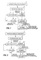
- FIG. 1 and 2 are flow diagrams illustrating, respectively, two embodiments of the method of the invention;
- FIG. 3 illustrates an example of a scaling function utilized to map entropy values to sleep depth index values;
- FIG. 4 illustrates an embodiment of the invention, in which the detection of REM sleep is based on a bioimpedance measurement;
- FIGS. 5a to 5d illustrate the measured bioimpedance signal in different points of the impedance measurement branch of the apparatus of FIG.4;
- FIG. 6 illustrates one embodiment of an electrode configuration for measuring EEG and EOG signal data simultaneously;
- FIG. 7 illustrates one embodiment of the apparatus/system of the invention; and
- FIG. 8 and 9 illustrate different display modes of the apparatus of an embodiment of the invention.
- FIG. 1 illustrates one embodiment of the method of the present invention. As discussed above, an EEG signal is measured from a certain measurement area of the patient, such as the forehead (step 11). The measured signal is first digitized and the sampled biosignal may be filtered to exclude high- and low-frequency artifacts (step 12). As is common in the art, the digitized signal samples are processed as sets of sequential signal samples representing finite time blocks or time windows, commonly termed "epochs". The process continuously calculates the entropy values of the EEG signal data within the successive and possibly overlapping time windows (step 16). In this example, entropy refers to spectral entropy. However, instead of spectral entropy several other types of measures of irregularity may also be utilized, such as Shannon entropy or approximate entropy.
- Furthermore, the process continuously monitors the incoming EEG signal data in order to detect the periods of REM sleep (step 13). If a REM period is detected (
step 14/yes), the process modifies (step 15) the EEG signal data sequence input to the entropy calculation in order to add REM state information to the sequence. The modification may simply involve flagging of the signal values obtained during the REM sleep. The modification may also involve removal of the values corresponding to eye movements from the data sequence before the entropy calculation. The entropy values may then be calculated from the remaining data, i.e. from the gapped EEG data sequence. Optionally, the discarded data may be replaced by new values. This may be carried out by interpolating the new data values from non-rejected data points or by filling the gaps with predetermined constant values, such as zeroes. If the new data values do not unambiguously indicate a REM period, they may be flagged to indicate that they are obtained during REM sleep. - Based on the entropy sequence obtained from
step 16, the process then determines sleep depth indices in the successive time windows (step 17). The value of the index may be scaled to a fixed range, such as between 0 and 100, using an appropriate scaling function, for example. As a result of the REM detection, the sleep depth index sequence output fromstep 17 is provided with state information indicative of whether or not the index values in the sequence are based on EEG signal data obtained during a REM sleep period. If no index values are produced during the REM sleep, the state information serves to indicate the periods that correspond to REM sleep. As discussed below, the index sequence may be employed to indicate the REM sleep periods with or without the index values that correspond to the REM sleep periods. - In another embodiment, which is illustrated in FIG. 2, the sleep depth index is modified during the detected REM periods to attach the REM state information to the index sequence. In this embodiment, the modification of the EEG signal data sequence (
step 15 in FIG. 1) is thus omitted and the obtained sequence of the sleep depth index is modified according to the REM periods detected (step 18). The modification may simply involve flagging of the index values obtained during the REM sleep periods or replacing the respective index values with new values indicative of a REM sleep state. - FIG. 3 shows an example of a scaling function, which may be employed in
step 17 to map the entropy values to the index values. A relatively large portion of the original entropy scale corresponds to entropy values that do not normally occur during sleep. If spectral entropy is employed, the most interesting range of sleep depth lies between entropy values 0.5 and 1.0. Linear scaling from the original range into equidistant integer values from 0 to 100 would therefore result in a low resolution in the interesting range and in an unnecessarily high resolution in the low range. With the use of a nonlinear, e.g. a spline, function in the transform the resolution of the measurement may be enhanced in the interesting region of the original entropy scale. - The detection of the REM sleep periods may be based on a separate biosignal measurement or on the analysis of the measured EEG data sequence. Different methods for detecting the REM sleep are discussed below.
- In one embodiment of the invention, which is illustrated in FIG. 4, the detection of REM sleep is based on a bioimpedance measurement performed simultaneously with the EEG measurement. When applied to human facial areas, bioimpedance measurement provides information about blood flow, eye movements, and eye blinks, which affect the volume conduction properties.
- As is shown in FIG. 4, active electrodes A and B of an EEG measurement are attached in the facial area of a
patient 100, preferably onto the forehead of the patient. The EEG signal obtained from the electrodes is directed to an EEG measurement branch 4 comprising a low-pass filter 40 at its front end. - In the embodiment of FIG. 4, the excitation signal of the bioimpedance measurement is fed to the same electrodes from which the EEG signal is acquired. For supplying the excitation signal, the apparatus includes a
signal generator 49 connected to electrodes A and B throughcorresponding wires - The impedance signal is measured from the same electrodes by connecting an impedance measurement branch 3 to
wires pass filter 43 at its front end. - The low-
pass filter 40 of the EEG measurement branch prevents high frequencies, i.e. the excitation signal, from entering the EEG measurement branch, while the high-pass filter 43 prevents the low frequencies, i.e. the EEG signal, from entering the impedance measurement branch. - In the measurement branches the filtered signals are first amplified; the EEG signal is supplied to an
amplifier 41 of the EEG measurement branch, while the impedance signal is supplied to anamplifier 44 of the impedance measurement branch. The amplifiers are typically differential amplifiers. - The EEG measurement branch further includes an A/
D converter 42 that samples the EEG signal and converts it into digitized format. The A/D converter thus outputs a sequence of EEG signal data. After the low-pass filter 40, the EEG signal is processed in a conventional manner to obtain the said sequence. - In the 2-lead configuration of FIG. 4, the signal generator supplies an excitation current I to the patient. The voltage between the electrodes, i.e. the signal measured by the impedance measurement branch, is then proportional to the impedance of the signal path formed between electrodes A and B. At this stage, the frequency content of the measured signal is concentrated around the frequency of the excitation current. FIG. 5b illustrates the
impedance signal 20 output fromamplifier 44. As can be seen, impedance changes cause slow changes in the signal. - In order to analyze the impedance changes over time, the impedance signal is typically demodulated in a
detector 45 using the excitation frequency. This produces a time-varying signal indicating how the impedance of the signal path varies over time. As is shown in FIG. 5c, the detector typically outputs animpedance signal 21, which corresponds to the envelope of the rectifiedinput signal 20 and varies slowly over time in accordance with the impedance changes. This signal is then typically low-pass filtered in a first filter 46 in order to reduce noise and further high-pass filtered in asecond filter 47 to remove the often uninteresting DC component and low-frequency fluctuation. - The filtered impedance signal is then supplied to a REM detector 48, which compares the
impedance signal 21 with apredetermined threshold 22, as is illustrated in FIG. 5d, and determines the time periods during which the impedance signal exceeds the threshold. These periods are regarded as REM sleep periods and the temporal location of the periods is utilized to modify the EEG signal data sequence (as in FIG. 4) or the sleep depth index sequence. This is performed in amodification unit 15. As noted above, the DC value of the impedance signal is typically removed, in which case the alternating component of the impedance is compared with the threshold. - It is also possible to use an excitation frequency, which is at or close to the EEG frequency band. In this case both the EEG signal and the impedance signal may be amplified and digitized as one composite signal and the rest of the above-described steps may be implemented as software algorithms.
- As noted above, the bioimpedance measurement provides information about blood flow and thus includes a periodic component at a frequency corresponding to the pulse rate of the patient. Since the said component represents artifact from the point of view of the detection of eye movements (i.e. REM periods), the said pulsating component may be removed from the impedance signal in one embodiment of the invention. This may be performed in high-
pass filter 47 or in a separate removal unit before or after the high-pass filter, for example. - The bioimpedance measurement of FIG. 4 provides a user-friendly measurement arrangement, since only two electrodes with associated leads are needed.
- In another embodiment of the invention, the detection of REM sleep may be based on separate electro-oculographic (EOG) and EEG signals (channels). The EOG signal may be obtained using separate EOG electrodes or an electrode array designed for uncoupling the EEG and the EOG signals.
- FIG. 6 illustrates an
electrode configuration 600 that enables efficient detection of eye movements with a minimum number of electrodes. The electrode configuration comprises threemeasurement electrodes 61 to 63 of which the first and second electrodes are for measuring the EEG signal and the third and second electrodes for measuring the EOG signal. Thefirst electrode 61 is positioned onto the hairless fronto-lateral area of the frontal lobe of the patient, preferably as far as possible from the eye. Thesecond measurement electrode 62 is positioned similarly as the first measurement electrode, but on the opposite cortical hemisphere of the patient. Furthermore, the first and second electrodes are positioned substantially horizontally (i.e. in the same horizontal line) and at substantially equal distances from the vertical center axis VA of the face, i.e. the second measurement electrode is positioned onto the spot which is the mirror image of the spot of the first measurement electrode, and vice versa, the vertical center axis being the mirror axis. - The EEG signal is measured from the first and
second measurement electrodes third measurement electrode 63 and one of the first and second measurement electrodes are employed to measure the EOG signal. For this purpose, the third measurement electrode is positioned so that the EOG voltage measured between this electrode and one of the first and second electrodes is as high as possible in case of horizontal movement of the eyes. In the example of FIG. 6, the said one electrode is thesecond measurement electrode 62, i.e. the EOG voltage is measured betweenelectrodes measurement electrode 62. The temple here refers to the area between an eye and the ear on the same hemisphere as the eye. As to their internal structure, the electrodes may be similar to each other. Various other electrode configurations that enable the detection of eye movements with a minimum number of electrodes are disclosed inU.S. Patent Application No. 11/316,374 . - For each epoch, the EOG signal may be utilized to detect eye movements and related REM periods. This may be done, for example, by examining whether the absolute value of any of the EOG signal values within an epoch exceeds a predetermined threshold value. Alternatively, the EEG and EOG signals may be compared with each other in order to detect the REM periods. This may be done, for example, by determining the difference of the absolute values of simultaneous EOG and EEG signal values for each sample in an epoch (|SEOG(ti)| - |SEEG(ti)|). It may then be examined whether any of the differences exceeds a predetermined threshold. If this is the case, the entropy or index value corresponding to the epoch is flagged or modified to indicate that REM sleep is involved.
- In a further embodiment, an electromyographic (EMG) signal may be used to further rule out periods of high EOG activity during which the patient is not asleep. Since EMG activity is at its minimum during REM sleep, the EMG channel may be used to indicate when REM sleep is not involved even though the comparison with the threshold indicates REM sleep. Thus in this embodiment the entropy or index value corresponding to an epoch is flagged or modified, if any of the above absolute values or differences in the epoch exceeds the associated threshold and if the EMG value is simultaneously below a respective threshold indicating that the patient is asleep.
- FIG. 7 illustrates one embodiment of the system or apparatus according to the invention. It is assumed here that the detection of REM sleep is based on the bioimpedance measurement shown in FIG. 4. Similar elements have been provided with the same reference numbers as above, and
elements 43 to 47 of FIG. 4 are denoted with one block. In this embodiment, the digitized EEG signal data is supplied to acontrol unit 73 which may comprise one or more computer units or processors. The impedance signal output from high-pass filter 47 is converted into digitized format in an A/D converter 70, which supplies the digitized impedance signal to the control unit. In this embodiment, the control unit thus takes over the role of theREM detector 14. In other words, the control unit compares the impedance signal with the predetermined threshold and detects the REM periods in the EEG signal data. Based on the EEG signal data sequence, the control unit further calculates the entropy value sequence and the sleep depth index sequence. Depending on the embodiment, the control unit may flag or modify the EEG sequence or the sleep depth index sequence based on the detected REM periods. - The control unit is provided with a memory or
database 76 holding the digitized EEG data and the digitized impedance data. The memory or database may also store the algorithm for analyzing the impedance data, various parameters needed in the REM detection, such as the threshold value with which the impedance signal is compared, and the calculation algorithms for calculating the entropy values and the sleep depth indices. - The sleep depth index signal may then be displayed on the screen of a
monitor 74, which forms part of the user interface of the apparatus/system. As is shown in FIG. 8, the index sequence may be flagged to indicate the REM periods. In this display mode, the REM segments of the sleep depth index curve are thus marked to allow the user to distinguish the REM segments from the sequence. The REM segments may be indicated, for example, by using a different color for the sleep depth index curve during the REM periods. - In another display mode, shown in FIG. 9, the REM periods are shown as a separate REM state which is outside the value range of the sleep depth index. The display mode of the apparatus may be selected independently of whether the embodiment of FIG. 1 or 2 is in question.
- Although a control unit comprising one computer unit or one processor may perform the above steps, the processing of the data may also be distributed among different units/processors (servers) within a network, such as a hospital LAN (local area network). The apparatus of the invention may thus also be implemented as a distributed system.
- The user may control the operation of the apparatus/system through a
user input device 75, such as a keyboard. As discussed above, the bioimpedance measurement elements, denoted withreference number 79, may also be replaced by EOG measurement elements for detecting the REM and non-REM sleep periods. In this case the control unit may thus determine, for example, the difference of the absolute values of simultaneous EOG and EEG signal values for each sample in an epoch or the highest absolute EOG signal value in an epoch, and examine, respectively, whether any of the differences or the said highest absolute value exceeds the respective threshold. If this is the case, the control unit flags or modifies the EEG signal values or the index value corresponding to the epoch to indicate that REM sleep is involved. - A patient monitor in which EEG data and continuous bioimpedance or EOG data are available may also be upgraded to enable the monitor to provide information about the depth of sleep of the patient. Such an upgrade may be implemented by delivering to the patient monitor a software module that enables the device to detect the REM periods and determine the sleep depth index sequence in the above-described manner. The software module may be delivered, for example, on a data carrier, such as a CD or a memory card, or through a telecommunications network. The software module may be provided with interfaces for receiving EEG and impedance/EOG data. The software module then performs, utilizing the impedance/EOG data available, the above-described REM detection and outputs a modified or flagged index sequence in which the REM sleep periods are indicated. The software module may receive the EEG and bioimpedance/EOG signals in real-time directly from the electrodes of the monitor or from the memory of the patient monitor after the actual measurement. In the latter case, the signals may already be temporally aligned by time stamps attached to the signal values. As also discussed above, the EOG data may be associated with EMG data to rule out periods of high EOG activity during which the patient is not asleep.
- Although the invention was described above with reference to the examples shown in the appended drawings, it is clear that the invention is not limited to these, but may be modified by those skilled in the art without departing from the scope of the invention. For example, instead of the EEG data sequence or the index sequence the REM sleep periods of the entropy sequence may also be modified or flagged to indicate that REM sleep is involved. Instead of a continuous index sequence, the mechanism of the invention may also be employed to determine distinct index values provided with REM state information.
- Various aspects and embodiments of the invention are now defined in the following numbered clauses:
- 1. A method for determining the depth of sleep of a subject, the method comprising the steps of:
- acquiring (11) EEG signal data from a subject;
- detecting (13) REM sleep periods of the subject;
- deriving (16) a measure indicative of irregularity in the EEG signal data; and
- producing (17), based on the measure and the detecting step, a sleep depth index indicative of the depth of sleep of the subject and state information indicative of whether the EEG signal data is obtained during a REM sleep period.
- 2. A method according to
clause 1, wherein
the deriving step includes deriving a sequence of the measure; and
the producing step includes producing a sequence of the sleep depth index. - 3. A method according to
clause 1 orclause 2, wherein the detecting step includes the sub-steps of:- supplying an AC excitation signal through a signal path formed between two electrodes of an electrode set attached to the subject's skin surface in a measurement area of the subject's body;
- measuring an impedance signal through the electrode set, the impedance signal being indicative of the impedance of the signal path;
- determining at least one time period during which the impedance signal fulfills at least one predetermined criterion; and
- defining the REM sleep periods based on the at least one time period.
- 4. A method according to clause 3, wherein the determining sub-step includes a sub-step of comparing the impedance signal with a predetermined threshold value.
- 5. A method according to any preceding clause, further comprising a step of discarding selected segments of the EEG signal data, the selected segments corresponding to the REM sleep periods detected in the detecting step.
- 6. A method according to clause 5, further comprising a step of replacing the selected segments with new signal values.
- 7. A method according to any preceding clause, wherein the producing step includes a sub-step of converting the measure or values in the sequence of the measure to a predetermined value range, thereby to obtain, respectively, the sleep depth index or the sequence of the sleep depth index.
- 8. A method according to clause 7, further comprising the steps of:
- displaying the sequence of the sleep depth index for non-REM sleep periods; and indicating, based on the state information, the REM periods as a separate REM sleep state distinct from the predetermined value range.
- 9. A method according to clause 7 or
clause 8, further comprising the steps of:- displaying the sequence of the sleep depth index for the REM and non-REM sleep periods; and
- based on the state information, expressing the sequence differently for the REM and non-REM periods.
- 10. A method according to any preceding clause, wherein the deriving step includes deriving the measure indicative of irregularity in the EEG signal data, in which the measure is indicative of spectral entropy of the EEG signal data.
- 11. A method according to any preceding clause, wherein the detecting step includes the sub-steps of:
- acquiring EOG signal data from the subject; and-utilizing the EOG signal data for defining the REM sleep periods.
- 12. A method according to
clause 11, wherein the utilizing sub-step includes comparing the EOG signal data with a predetermined threshold or with the EEG signal data. - 13. An apparatus for determining the depth of sleep of a subject, the apparatus comprising:
- means (A, B, 4, 40-42) for acquiring EEG signal data from a subject;
- detection means (A, B, 3, 43-47, 70, 73) for detecting REM sleep periods of the subject;
- first calculation means (73, 76) for deriving a measure indicative of irregularity in the EEG signal data; and
- second calculation means (73, 76), responsive to the first calculation means and the detection means, for producing a sleep depth index indicative of the depth of sleep of the subject and state information indicative of whether the EEG signal data is obtained during a REM sleep period.
- 14. An apparatus according to
clause 13, wherein
the first calculation means are constructed to derive a sequence of the measure; and
the second calculation means are constructed to produce a sequence of the sleep depth index. - 15. An apparatus according to
clause 13 orclause 14, wherein the detection means comprise:- signal generator means (49) for supplying an AC excitation signal through a signal path formed between two electrodes (A, B) of an electrode set when said set is attached to a subject's skin surface in a measurement area of the subject's body;
- impedance measurement means (43-47) for measuring an impedance signal through the electrode set, the impedance signal being indicative of the impedance of the signal path;
- first means (48, 73) for determining at least one time period during which the impedance signal fulfills at least one predetermined criterion; and
second means (48, 73) for defining the REM sleep periods based on the at least one time period.
- 16. An apparatus according to
clause 15, wherein the first means are configured to compare the impedance signal with a predetermined threshold value (22). - 17. An apparatus according to any one of
clauses 13 to 16, wherein the first calculation means are configured to discard selected segments of the EEG signal data, the selected segments corresponding to the REM sleep periods detected by the detection means. - 18. An apparatus according to
clause 17, wherein the first calculation means are further configured to replace the selected segments with new signal values. - 19. An apparatus according to any one of
clauses 13 to 18, wherein the second calculation means are configured to convert values in the sequence of the measure to a predetermined value range, thereby to obtain the sequence of the sleep depth index. - 20. An apparatus according to clause 19, further comprising display means (73, 74) for displaying the sequence of the sleep depth index for non-REM sleep periods and for indicating, based on the state information, the REM periods as a separate REM sleep state distinct from the predetermined value range.
- 21. An apparatus according to
clause 19 or 20, further comprising display means (73, 74) for displaying the sequence of the sleep depth index for the REM and non-REM sleep periods and for expressing, based on the state information, the sequence differently for the REM and non-REM periods. - 22. An apparatus according to any one of
clauses 13 to 21, wherein the measure indicative of irregularity in the EEG signal data is indicative of spectral entropy of the EEG signal data. - 23. An apparatus according to any one of
clauses 13 to 22, further comprising means (600) for acquiring EOG signal data from the subject. - 24. An apparatus according to clause 23, wherein the detection means are configured to define the REM sleep periods based on the EOG signal data or based on the EOG signal data and the EEG signal data.
- 25. A computer program product for determining the depth of sleep of a subject, the computer program product comprising:
- a first program code portion configured to receive EEG signal data obtained from a subject;
- a second program code portion configured to detect REM sleep periods of the subject;
- a third program code portion configured to derive a measure indicative of irregularity in the EEG signal data; and
- a fourth program code portion configured to determine, based on the measure and detected REM periods, a sleep depth index indicative of the depth of sleep of the subject and state information indicative of whether the EEG signal data is obtained during a REM sleep period.
Claims (14)
- A method for determining the depth of sleep of a subject, the method comprising the steps of:acquiring (11) EEG signal data from a subject;detecting (13) REM sleep periods of the subject;deriving (16) a measure indicative of irregularity in the EEG signal data; andproducing (17), based on the measure and the detecting step, a sleep depth index indicative of the depth of sleep of the subject and state information indicative of whether the EEG signal data is obtained during a REM sleep period.
- A method according to claim 1, wherein
the deriving step includes deriving a sequence of the measure; and
the producing step includes producing a sequence of the sleep depth index. - A method according to claim 1 or claim 2, wherein the detecting step includes the sub-steps of:supplying an AC excitation signal through a signal path formed between two electrodes of an electrode set attached to the subject's skin surface in a measurement area of the subject's body;measuring an impedance signal through the electrode set, the impedance signal being indicative of the impedance of the signal path;determining at least one time period during which the impedance signal fulfills at least one predetermined criterion; anddefining the REM sleep periods based on the at least one time period.
- A method according to claim 3, wherein the determining sub-step includes a sub-step of comparing the impedance signal with a predetermined threshold value.
- A method according to any preceding claim, further comprising a step of discarding selected segments of the EEG signal data, the selected segments corresponding to the REM sleep periods detected in the detecting step.
- A method according to claim 5, further comprising a step of replacing the selected segments with new signal values.
- A method according to any preceding claim, wherein the producing step includes a sub-step of converting the measure or values in the sequence of the measure to a predetermined value range, thereby to obtain, respectively, the sleep depth index or the sequence of the sleep depth index.
- A method according to claim 7, further comprising the steps of:displaying the sequence of the sleep depth index for non-REM sleep periods; and indicating, based on the state information, the REM periods as a separate REM sleep state distinct from the predetermined value range.
- A method according to claim 7 or claim 8, further comprising the steps of:displaying the sequence of the sleep depth index for the REM and non-REM sleep periods; andbased on the state information, expressing the sequence differently for the REM and non-REM periods.
- A method according to any preceding claim, wherein the deriving step includes deriving the measure indicative of irregularity in the EEG signal data, in which the measure is indicative of spectral entropy of the EEG signal data.
- A method according to any preceding claim, wherein the detecting step includes the sub-steps of:acquiring EOG signal data from the subject; and-utilizing the EOG signal data for defining the REM sleep periods.
- A method according to claim 11, wherein the utilizing sub-step includes comparing the EOG signal data with a predetermined threshold or with the EEG signal data.
- An apparatus for determining the depth of sleep of a subject, the apparatus comprising:means (A, B, 4, 40-42) for acquiring EEG signal data from a subject;detection means (A, B, 3, 43-47, 70, 73) for detecting REM sleep periods of the subject;first calculation means (73, 76) for deriving a measure indicative of irregularity in the EEG signal data; andsecond calculation means (73, 76), responsive to the first calculation means and the detection means, for producing a sleep depth index indicative of the depth of sleep of the subject and state information indicative of whether the EEG signal data is obtained during a REM sleep period.
- A computer program product for determining the depth of sleep of a subject, the computer program product comprising:a first program code portion configured to receive EEG signal data obtained from a subject;a second program code portion configured to detect REM sleep periods of the subject;a third program code portion configured to derive a measure indicative of irregularity in the EEG signal data; anda fourth program code portion configured to determine, based on the measure and detected REM periods, a sleep depth index indicative of the depth of sleep of the subject and state information indicative of whether the EEG signal data is obtained during a REM sleep period.
Applications Claiming Priority (1)
| Application Number | Priority Date | Filing Date | Title |
|---|---|---|---|
| US11/438,637 US7848795B2 (en) | 2006-05-22 | 2006-05-22 | Determination of sleep depth |
Publications (2)
| Publication Number | Publication Date |
|---|---|
| EP1859736A1 true EP1859736A1 (en) | 2007-11-28 |
| EP1859736B1 EP1859736B1 (en) | 2017-07-19 |
Family
ID=38470151
Family Applications (1)
| Application Number | Title | Priority Date | Filing Date |
|---|---|---|---|
| EP07108405.7A Not-in-force EP1859736B1 (en) | 2006-05-22 | 2007-05-17 | Determination of sleep depth |
Country Status (2)
| Country | Link |
|---|---|
| US (1) | US7848795B2 (en) |
| EP (1) | EP1859736B1 (en) |
Cited By (3)
| Publication number | Priority date | Publication date | Assignee | Title |
|---|---|---|---|---|
| WO2010060153A1 (en) * | 2008-11-28 | 2010-06-03 | The University Of Queensland | A method and apparatus for determining sleep states |
| EP2495005A4 (en) * | 2009-10-30 | 2014-07-02 | Toyota Motor Co Ltd | STIMULATION EFFECT EVALUATION DEVICE, SLEEP DEPTH EVALUATION DEVICE, STIMULUS EFFECT EVALUATION METHOD, AND VEHICLE CONTROL UNIT |
| CN108553084A (en) * | 2018-03-09 | 2018-09-21 | 浙江纽若思医疗科技有限公司 | A kind of recognition methods, device and the equipment of sleep stage event |
Families Citing this family (15)
| Publication number | Priority date | Publication date | Assignee | Title |
|---|---|---|---|---|
| US7996076B2 (en) * | 2007-04-02 | 2011-08-09 | The Regents Of The University Of Michigan | Automated polysomnographic assessment for rapid eye movement sleep behavior disorder |
| WO2009002238A1 (en) * | 2007-06-27 | 2008-12-31 | St. Jude Medical Ab | A method and device for collecting rem sleep data |
| WO2009002237A1 (en) * | 2007-06-27 | 2008-12-31 | St. Jude Medical Ab | A method and device for detecting rem sleep |
| US20090024044A1 (en) * | 2007-07-17 | 2009-01-22 | The General Electric Company | Data recording for patient status analysis |
| WO2010004698A1 (en) * | 2008-07-11 | 2010-01-14 | パナソニック株式会社 | Method for controlling device by using brain wave and brain wave interface system |
| US9186083B2 (en) * | 2009-02-24 | 2015-11-17 | Natus Medical Incorporated | Method and system for sleep stage determination |
| EP2236078A1 (en) * | 2009-04-02 | 2010-10-06 | Koninklijke Philips Electronics N.V. | Processing a bio-physiological signal |
| EP2460464A1 (en) | 2010-12-03 | 2012-06-06 | Koninklijke Philips Electronics N.V. | Sleep disturbance monitoring apparatus |
| US8573980B2 (en) | 2011-04-04 | 2013-11-05 | Sheepdog Sciences, Inc. | Apparatus, system, and method for modulating consolidation of memory during sleep |
| US20140057232A1 (en) * | 2011-04-04 | 2014-02-27 | Daniel Z. Wetmore | Apparatus, system, and method for modulating consolidation of memory during sleep |
| WO2012138761A1 (en) * | 2011-04-04 | 2012-10-11 | Sheepdog Sciences, Inc. | Apparatus, system, and method for modulating consolidation of memory during sleep |
| US9113805B2 (en) | 2013-03-04 | 2015-08-25 | Mortara Instrument, Inc. | Impedance measurement system |
| US9620027B2 (en) * | 2013-03-14 | 2017-04-11 | Incube Labs, Llc | Systems and methods for delivering sensory input during a dream state |
| CN105942974A (en) * | 2016-04-14 | 2016-09-21 | 禅客科技(上海)有限公司 | Sleep analysis method and system based on low frequency electroencephalogram |
| CN109669546B (en) * | 2019-01-30 | 2022-06-07 | 浙江强脑科技有限公司 | Music playing control method and device and computer readable storage medium |
Citations (4)
| Publication number | Priority date | Publication date | Assignee | Title |
|---|---|---|---|---|
| US5154180A (en) | 1990-01-24 | 1992-10-13 | France Telecom | Method and device for determining a subject's sleep state by processing an electroencephalographic signal |
| US6272378B1 (en) | 1996-11-21 | 2001-08-07 | 2Rcw Gmbh | Device and method for determining sleep profiles |
| US20050020934A1 (en) * | 2001-11-01 | 2005-01-27 | Charles Potter | Physiological monitoring |
| US20050137494A1 (en) | 2003-10-22 | 2005-06-23 | Viertio-Oja Hanna E. | Method and apparatus for determining the cerebral state of a patient using generalized spectral entropy of the EEG signal |
Family Cites Families (10)
| Publication number | Priority date | Publication date | Assignee | Title |
|---|---|---|---|---|
| GB9522872D0 (en) * | 1995-11-08 | 1996-01-10 | Oxford Medical Ltd | Improvements relating to physiological monitoring |
| US6731975B1 (en) * | 2000-10-16 | 2004-05-04 | Instrumentarium Corp. | Method and apparatus for determining the cerebral state of a patient with fast response |
| CA2448806C (en) * | 2001-06-13 | 2011-10-18 | Compumedics Limited | Methods and apparatus for monitoring consciousness |
| US7248915B2 (en) * | 2004-02-26 | 2007-07-24 | Nokia Corporation | Natural alarm clock |
| US7578793B2 (en) * | 2004-11-22 | 2009-08-25 | Widemed Ltd. | Sleep staging based on cardio-respiratory signals |
| US7625340B2 (en) * | 2004-12-02 | 2009-12-01 | Instrumentarium Corporation | Identification of a dominant signal component in a biosignal |
| JP4342455B2 (en) * | 2005-02-03 | 2009-10-14 | 株式会社東芝 | Health management device and health management system |
| JP4528710B2 (en) * | 2005-11-09 | 2010-08-18 | 株式会社東芝 | Sleep state measurement device, sleep state measurement method, and sleep state measurement system |
| JP4357503B2 (en) * | 2006-06-28 | 2009-11-04 | 株式会社東芝 | Biological information measuring device, biological information measuring method, and biological information measuring program |
| JP2008229248A (en) * | 2007-03-23 | 2008-10-02 | Toshiba Corp | Sleep control device, method and program |
-
2006
- 2006-05-22 US US11/438,637 patent/US7848795B2/en active Active
-
2007
- 2007-05-17 EP EP07108405.7A patent/EP1859736B1/en not_active Not-in-force
Patent Citations (4)
| Publication number | Priority date | Publication date | Assignee | Title |
|---|---|---|---|---|
| US5154180A (en) | 1990-01-24 | 1992-10-13 | France Telecom | Method and device for determining a subject's sleep state by processing an electroencephalographic signal |
| US6272378B1 (en) | 1996-11-21 | 2001-08-07 | 2Rcw Gmbh | Device and method for determining sleep profiles |
| US20050020934A1 (en) * | 2001-11-01 | 2005-01-27 | Charles Potter | Physiological monitoring |
| US20050137494A1 (en) | 2003-10-22 | 2005-06-23 | Viertio-Oja Hanna E. | Method and apparatus for determining the cerebral state of a patient using generalized spectral entropy of the EEG signal |
Non-Patent Citations (6)
| Title |
|---|
| BURIOKA: "Approximate Entropy in the Electroencephalogram During Wake and Sleep", CLINICAL EEG AND NEUROSCIENCE, vol. 36, no. 1, pages 21 - 24, XP009089645 |
| FLEXER: "A reliable probabilistic sleep stager based on a single EEG signal", ARTIFICIAL INTELLIGENCE IN MEDICINE, vol. 33, 2005, pages 199 - 207, XP025317518, DOI: doi:10.1016/j.artmed.2004.04.004 |
| KOMAN J ET AL: "AUTOMATING THE SLEEP LABORATORY: IMPLEMENTATION AND VALIDATION OF DIGITAL RECORDING AND ANALYSIS", INTERNATIONAL JOURNAL OF BIO-MEDICAL COMPUTING, ELSEVIER SCIENCE PUBLISHERS, SHANNON, IE, vol. 38, no. 3, 1 March 1995 (1995-03-01), pages 277 - 290, XP000501211, ISSN: 0020-7101 * |
| LI QUANZHENG ET AL: "Subsection approximate entropy and its application in sleep staging", BMES/EMBS CONFERENCE, 1999. PROCEEDINGS OF THE FIRST JOINT ATLANTA, GA, USA 13-16 OCT. 1999, PISCATAWAY, NJ, USA,IEEE, US, vol. 2, 13 October 1999 (1999-10-13), pages 900, XP010357787, ISBN: 0-7803-5674-8 * |
| UCHIDA S ET AL: "HUMAN SLEEP ELECTROENCEPHALOGRAM ANALYSIS BASED ON THE INSTANTANEOUS MAXIMUM ENTROPY METHOD", IEICE TRANSACTIONS ON FUNDAMENTALS OF ELECTRONICS, COMMUNICATIONS AND COMPUTER SCIENCES, ENGINEERING SCIENCES SOCIETY, TOKYO, JP, vol. E80-A, no. 6, June 1997 (1997-06-01), pages 965 - 970, XP000740591, ISSN: 0916-8508 * |
| WEI-XING HE ET AL: "Nonlinear Feature Extraction of Sleeping EEG Signals", ENGINEERING IN MEDICINE AND BIOLOGY SOCIETY, 2005. IEEE-EMBS 2005. 27TH ANNUAL INTERNATIONAL CONFERENCE OF THE SHANGHAI, CHINA 01-04 SEPT. 2005, PISCATAWAY, NJ, USA,IEEE, 1 September 2005 (2005-09-01), pages 4614 - 4617, XP010906816, ISBN: 0-7803-8741-4 * |
Cited By (7)
| Publication number | Priority date | Publication date | Assignee | Title |
|---|---|---|---|---|
| WO2010060153A1 (en) * | 2008-11-28 | 2010-06-03 | The University Of Queensland | A method and apparatus for determining sleep states |
| US20110301487A1 (en) * | 2008-11-28 | 2011-12-08 | The University Of Queensland | Method and apparatus for determining sleep states |
| US10575751B2 (en) | 2008-11-28 | 2020-03-03 | The University Of Queensland | Method and apparatus for determining sleep states |
| EP2495005A4 (en) * | 2009-10-30 | 2014-07-02 | Toyota Motor Co Ltd | STIMULATION EFFECT EVALUATION DEVICE, SLEEP DEPTH EVALUATION DEVICE, STIMULUS EFFECT EVALUATION METHOD, AND VEHICLE CONTROL UNIT |
| US8948862B2 (en) | 2009-10-30 | 2015-02-03 | Toyota Jidosha Kabushiki Kaisha | Stimulatory effect estimation device, sleep depth estimation device, stimulatory effect estimation method, and vehicle control device |
| CN108553084A (en) * | 2018-03-09 | 2018-09-21 | 浙江纽若思医疗科技有限公司 | A kind of recognition methods, device and the equipment of sleep stage event |
| CN108553084B (en) * | 2018-03-09 | 2021-05-25 | 浙江纽若思医疗科技有限公司 | Sleep staging event identification method, device and equipment |
Also Published As
| Publication number | Publication date |
|---|---|
| EP1859736B1 (en) | 2017-07-19 |
| US7848795B2 (en) | 2010-12-07 |
| US20070270706A1 (en) | 2007-11-22 |
Similar Documents
| Publication | Publication Date | Title |
|---|---|---|
| EP1859736B1 (en) | Determination of sleep depth | |
| US7684856B2 (en) | Detection of artifacts in bioelectric signals | |
| JP4532739B2 (en) | Warning and drowsiness detection and tracking system | |
| US20070135727A1 (en) | Detection of artifacts in bioelectric signals | |
| US7570991B2 (en) | Method for real time attitude assessment | |
| US8798735B1 (en) | Method and apparatus for the estimation of anesthetic depth using wavelet analysis of the electroencephalogram | |
| US5999846A (en) | Physiological monitoring | |
| JP4020214B2 (en) | Method and device for assessing EEG performed in anesthesia or intensive care | |
| US5775330A (en) | Neurometric assessment of intraoperative anesthetic | |
| US20090024044A1 (en) | Data recording for patient status analysis | |
| EP1880667B1 (en) | Detection of focal epileptiform activity | |
| CN113288174B (en) | Method for detecting cognitive function of schizophrenic patient | |
| CN113100776A (en) | Fatigue monitoring system and method fusing myoelectric signal and electrocardiosignal | |
| CN115316957A (en) | Perioperative anesthesia depth monitoring system based on multi-parameter indexes | |
| KR100719068B1 (en) | Health diagnosis device and its method using pattern analysis of cumulative data through fast Fourier transform of EEG data measured in frontal lobe | |
| CN105188525A (en) | Method and system to calculate quantitative EEG | |
| CN116369853B (en) | Olfactory function standardized evaluation device and method based on brain-computer interaction technology | |
| EL Hadiri et al. | Profound sedation detection based on brain waves analysis | |
| KR102452201B1 (en) | Automatic noise signal section detection method and apparatus | |
| CN105144225A (en) | Multiple patient EEG monitoring | |
| Jayas et al. | Computer aided detection of dominant artifacts in ear-EEG signal | |
| WO2008040846A1 (en) | Apparatus and method for determining the functional state of a brain | |
| Adib et al. | Enhanced Joint Heart and Respiratory Rates Extraction from Functional Near-infrared Spectroscopy Signals Using Cumulative Curve Fitting Approximation | |
| Kemp | Measurement of sleep | |
| JP2004350797A (en) | Method and apparatus for evaluating brain wave |
Legal Events
| Date | Code | Title | Description |
|---|---|---|---|
| PUAI | Public reference made under article 153(3) epc to a published international application that has entered the european phase |
Free format text: ORIGINAL CODE: 0009012 |
|
| AK | Designated contracting states |
Kind code of ref document: A1 Designated state(s): AT BE BG CH CY CZ DE DK EE ES FI FR GB GR HU IE IS IT LI LT LU LV MC MT NL PL PT RO SE SI SK TR |
|
| AX | Request for extension of the european patent |
Extension state: AL BA HR MK YU |
|
| 17P | Request for examination filed |
Effective date: 20080528 |
|
| 17Q | First examination report despatched |
Effective date: 20080704 |
|
| AKX | Designation fees paid |
Designated state(s): AT BE BG CH CY CZ DE DK EE ES FI FR GB GR HU IE IS IT LI LT LU LV MC MT NL PL PT RO SE SI SK TR |
|
| GRAP | Despatch of communication of intention to grant a patent |
Free format text: ORIGINAL CODE: EPIDOSNIGR1 |
|
| GRAS | Grant fee paid |
Free format text: ORIGINAL CODE: EPIDOSNIGR3 |
|
| GRAA | (expected) grant |
Free format text: ORIGINAL CODE: 0009210 |
|
| INTG | Intention to grant announced |
Effective date: 20170526 |
|
| AK | Designated contracting states |
Kind code of ref document: B1 Designated state(s): AT BE BG CH CY CZ DE DK EE ES FI FR GB GR HU IE IS IT LI LT LU LV MC MT NL PL PT RO SE SI SK TR |
|
| REG | Reference to a national code |
Ref country code: GB Ref legal event code: FG4D |
|
| REG | Reference to a national code |
Ref country code: CH Ref legal event code: EP |
|
| REG | Reference to a national code |
Ref country code: IE Ref legal event code: FG4D |
|
| REG | Reference to a national code |
Ref country code: AT Ref legal event code: REF Ref document number: 909563 Country of ref document: AT Kind code of ref document: T Effective date: 20170815 |
|
| REG | Reference to a national code |
Ref country code: DE Ref legal event code: R096 Ref document number: 602007051664 Country of ref document: DE |
|
| REG | Reference to a national code |
Ref country code: NL Ref legal event code: MP Effective date: 20170719 |
|
| REG | Reference to a national code |
Ref country code: LT Ref legal event code: MG4D |
|
| REG | Reference to a national code |
Ref country code: AT Ref legal event code: MK05 Ref document number: 909563 Country of ref document: AT Kind code of ref document: T Effective date: 20170719 |
|
| PG25 | Lapsed in a contracting state [announced via postgrant information from national office to epo] |
Ref country code: NL Free format text: LAPSE BECAUSE OF FAILURE TO SUBMIT A TRANSLATION OF THE DESCRIPTION OR TO PAY THE FEE WITHIN THE PRESCRIBED TIME-LIMIT Effective date: 20170719 Ref country code: AT Free format text: LAPSE BECAUSE OF FAILURE TO SUBMIT A TRANSLATION OF THE DESCRIPTION OR TO PAY THE FEE WITHIN THE PRESCRIBED TIME-LIMIT Effective date: 20170719 Ref country code: FI Free format text: LAPSE BECAUSE OF FAILURE TO SUBMIT A TRANSLATION OF THE DESCRIPTION OR TO PAY THE FEE WITHIN THE PRESCRIBED TIME-LIMIT Effective date: 20170719 Ref country code: SE Free format text: LAPSE BECAUSE OF FAILURE TO SUBMIT A TRANSLATION OF THE DESCRIPTION OR TO PAY THE FEE WITHIN THE PRESCRIBED TIME-LIMIT Effective date: 20170719 Ref country code: LT Free format text: LAPSE BECAUSE OF FAILURE TO SUBMIT A TRANSLATION OF THE DESCRIPTION OR TO PAY THE FEE WITHIN THE PRESCRIBED TIME-LIMIT Effective date: 20170719 |
|
| PG25 | Lapsed in a contracting state [announced via postgrant information from national office to epo] |
Ref country code: PL Free format text: LAPSE BECAUSE OF FAILURE TO SUBMIT A TRANSLATION OF THE DESCRIPTION OR TO PAY THE FEE WITHIN THE PRESCRIBED TIME-LIMIT Effective date: 20170719 Ref country code: BG Free format text: LAPSE BECAUSE OF FAILURE TO SUBMIT A TRANSLATION OF THE DESCRIPTION OR TO PAY THE FEE WITHIN THE PRESCRIBED TIME-LIMIT Effective date: 20171019 Ref country code: GR Free format text: LAPSE BECAUSE OF FAILURE TO SUBMIT A TRANSLATION OF THE DESCRIPTION OR TO PAY THE FEE WITHIN THE PRESCRIBED TIME-LIMIT Effective date: 20171020 Ref country code: LV Free format text: LAPSE BECAUSE OF FAILURE TO SUBMIT A TRANSLATION OF THE DESCRIPTION OR TO PAY THE FEE WITHIN THE PRESCRIBED TIME-LIMIT Effective date: 20170719 Ref country code: IS Free format text: LAPSE BECAUSE OF FAILURE TO SUBMIT A TRANSLATION OF THE DESCRIPTION OR TO PAY THE FEE WITHIN THE PRESCRIBED TIME-LIMIT Effective date: 20171119 Ref country code: ES Free format text: LAPSE BECAUSE OF FAILURE TO SUBMIT A TRANSLATION OF THE DESCRIPTION OR TO PAY THE FEE WITHIN THE PRESCRIBED TIME-LIMIT Effective date: 20170719 |
|
| REG | Reference to a national code |
Ref country code: DE Ref legal event code: R097 Ref document number: 602007051664 Country of ref document: DE |
|
| PG25 | Lapsed in a contracting state [announced via postgrant information from national office to epo] |
Ref country code: CZ Free format text: LAPSE BECAUSE OF FAILURE TO SUBMIT A TRANSLATION OF THE DESCRIPTION OR TO PAY THE FEE WITHIN THE PRESCRIBED TIME-LIMIT Effective date: 20170719 Ref country code: DK Free format text: LAPSE BECAUSE OF FAILURE TO SUBMIT A TRANSLATION OF THE DESCRIPTION OR TO PAY THE FEE WITHIN THE PRESCRIBED TIME-LIMIT Effective date: 20170719 Ref country code: RO Free format text: LAPSE BECAUSE OF FAILURE TO SUBMIT A TRANSLATION OF THE DESCRIPTION OR TO PAY THE FEE WITHIN THE PRESCRIBED TIME-LIMIT Effective date: 20170719 |
|
| PLBE | No opposition filed within time limit |
Free format text: ORIGINAL CODE: 0009261 |
|
| REG | Reference to a national code |
Ref country code: FR Ref legal event code: PLFP Year of fee payment: 12 |
|
| STAA | Information on the status of an ep patent application or granted ep patent |
Free format text: STATUS: NO OPPOSITION FILED WITHIN TIME LIMIT |
|
| PG25 | Lapsed in a contracting state [announced via postgrant information from national office to epo] |
Ref country code: IT Free format text: LAPSE BECAUSE OF FAILURE TO SUBMIT A TRANSLATION OF THE DESCRIPTION OR TO PAY THE FEE WITHIN THE PRESCRIBED TIME-LIMIT Effective date: 20170719 Ref country code: EE Free format text: LAPSE BECAUSE OF FAILURE TO SUBMIT A TRANSLATION OF THE DESCRIPTION OR TO PAY THE FEE WITHIN THE PRESCRIBED TIME-LIMIT Effective date: 20170719 Ref country code: SK Free format text: LAPSE BECAUSE OF FAILURE TO SUBMIT A TRANSLATION OF THE DESCRIPTION OR TO PAY THE FEE WITHIN THE PRESCRIBED TIME-LIMIT Effective date: 20170719 |
|
| 26N | No opposition filed |
Effective date: 20180420 |
|
| PG25 | Lapsed in a contracting state [announced via postgrant information from national office to epo] |
Ref country code: SI Free format text: LAPSE BECAUSE OF FAILURE TO SUBMIT A TRANSLATION OF THE DESCRIPTION OR TO PAY THE FEE WITHIN THE PRESCRIBED TIME-LIMIT Effective date: 20170719 |
|
| REG | Reference to a national code |
Ref country code: CH Ref legal event code: PL |
|
| REG | Reference to a national code |
Ref country code: BE Ref legal event code: MM Effective date: 20180531 |
|
| PG25 | Lapsed in a contracting state [announced via postgrant information from national office to epo] |
Ref country code: MC Free format text: LAPSE BECAUSE OF FAILURE TO SUBMIT A TRANSLATION OF THE DESCRIPTION OR TO PAY THE FEE WITHIN THE PRESCRIBED TIME-LIMIT Effective date: 20170719 |
|
| REG | Reference to a national code |
Ref country code: IE Ref legal event code: MM4A |
|
| PG25 | Lapsed in a contracting state [announced via postgrant information from national office to epo] |
Ref country code: LI Free format text: LAPSE BECAUSE OF NON-PAYMENT OF DUE FEES Effective date: 20180531 Ref country code: CH Free format text: LAPSE BECAUSE OF NON-PAYMENT OF DUE FEES Effective date: 20180531 |
|
| PG25 | Lapsed in a contracting state [announced via postgrant information from national office to epo] |
Ref country code: LU Free format text: LAPSE BECAUSE OF NON-PAYMENT OF DUE FEES Effective date: 20180517 |
|
| PG25 | Lapsed in a contracting state [announced via postgrant information from national office to epo] |
Ref country code: IE Free format text: LAPSE BECAUSE OF NON-PAYMENT OF DUE FEES Effective date: 20180517 |
|
| PG25 | Lapsed in a contracting state [announced via postgrant information from national office to epo] |
Ref country code: BE Free format text: LAPSE BECAUSE OF NON-PAYMENT OF DUE FEES Effective date: 20180531 |
|
| PG25 | Lapsed in a contracting state [announced via postgrant information from national office to epo] |
Ref country code: MT Free format text: LAPSE BECAUSE OF NON-PAYMENT OF DUE FEES Effective date: 20180517 |
|
| PG25 | Lapsed in a contracting state [announced via postgrant information from national office to epo] |
Ref country code: TR Free format text: LAPSE BECAUSE OF FAILURE TO SUBMIT A TRANSLATION OF THE DESCRIPTION OR TO PAY THE FEE WITHIN THE PRESCRIBED TIME-LIMIT Effective date: 20170719 |
|
| PG25 | Lapsed in a contracting state [announced via postgrant information from national office to epo] |
Ref country code: PT Free format text: LAPSE BECAUSE OF FAILURE TO SUBMIT A TRANSLATION OF THE DESCRIPTION OR TO PAY THE FEE WITHIN THE PRESCRIBED TIME-LIMIT Effective date: 20170719 Ref country code: HU Free format text: LAPSE BECAUSE OF FAILURE TO SUBMIT A TRANSLATION OF THE DESCRIPTION OR TO PAY THE FEE WITHIN THE PRESCRIBED TIME-LIMIT; INVALID AB INITIO Effective date: 20070517 |
|
| PG25 | Lapsed in a contracting state [announced via postgrant information from national office to epo] |
Ref country code: CY Free format text: LAPSE BECAUSE OF FAILURE TO SUBMIT A TRANSLATION OF THE DESCRIPTION OR TO PAY THE FEE WITHIN THE PRESCRIBED TIME-LIMIT Effective date: 20170719 |
|
| REG | Reference to a national code |
Ref country code: DE Ref legal event code: R079 Ref document number: 602007051664 Country of ref document: DE Free format text: PREVIOUS MAIN CLASS: A61B0005048000 Ipc: A61B0005374000 |
|
| PGFP | Annual fee paid to national office [announced via postgrant information from national office to epo] |
Ref country code: GB Payment date: 20220426 Year of fee payment: 16 Ref country code: FR Payment date: 20220421 Year of fee payment: 16 Ref country code: DE Payment date: 20220420 Year of fee payment: 16 |
|
| REG | Reference to a national code |
Ref country code: DE Ref legal event code: R119 Ref document number: 602007051664 Country of ref document: DE |
|
| GBPC | Gb: european patent ceased through non-payment of renewal fee |
Effective date: 20230517 |
|
| PG25 | Lapsed in a contracting state [announced via postgrant information from national office to epo] |
Ref country code: DE Free format text: LAPSE BECAUSE OF NON-PAYMENT OF DUE FEES Effective date: 20231201 Ref country code: GB Free format text: LAPSE BECAUSE OF NON-PAYMENT OF DUE FEES Effective date: 20230517 |
|
| PG25 | Lapsed in a contracting state [announced via postgrant information from national office to epo] |
Ref country code: FR Free format text: LAPSE BECAUSE OF NON-PAYMENT OF DUE FEES Effective date: 20230531 |