EP1857716A2 - Transmission driving mechanism of internal combustion engine - Google Patents
Transmission driving mechanism of internal combustion engine Download PDFInfo
- Publication number
- EP1857716A2 EP1857716A2 EP07106206A EP07106206A EP1857716A2 EP 1857716 A2 EP1857716 A2 EP 1857716A2 EP 07106206 A EP07106206 A EP 07106206A EP 07106206 A EP07106206 A EP 07106206A EP 1857716 A2 EP1857716 A2 EP 1857716A2
- Authority
- EP
- European Patent Office
- Prior art keywords
- shift
- internal combustion
- combustion engine
- clutch
- driving mechanism
- Prior art date
- Legal status (The legal status is an assumption and is not a legal conclusion. Google has not performed a legal analysis and makes no representation as to the accuracy of the status listed.)
- Granted
Links
Images



Classifications
-
- F—MECHANICAL ENGINEERING; LIGHTING; HEATING; WEAPONS; BLASTING
- F16—ENGINEERING ELEMENTS AND UNITS; GENERAL MEASURES FOR PRODUCING AND MAINTAINING EFFECTIVE FUNCTIONING OF MACHINES OR INSTALLATIONS; THERMAL INSULATION IN GENERAL
- F16H—GEARING
- F16H61/00—Control functions within control units of change-speed- or reversing-gearings for conveying rotary motion ; Control of exclusively fluid gearing, friction gearing, gearings with endless flexible members or other particular types of gearing
- F16H61/26—Generation or transmission of movements for final actuating mechanisms
- F16H61/28—Generation or transmission of movements for final actuating mechanisms with at least one movement of the final actuating mechanism being caused by a non-mechanical force, e.g. power-assisted
- F16H61/32—Electric motors , actuators or related electrical control means therefor
-
- F—MECHANICAL ENGINEERING; LIGHTING; HEATING; WEAPONS; BLASTING
- F16—ENGINEERING ELEMENTS AND UNITS; GENERAL MEASURES FOR PRODUCING AND MAINTAINING EFFECTIVE FUNCTIONING OF MACHINES OR INSTALLATIONS; THERMAL INSULATION IN GENERAL
- F16H—GEARING
- F16H63/00—Control outputs from the control unit to change-speed- or reversing-gearings for conveying rotary motion or to other devices than the final output mechanism
- F16H63/02—Final output mechanisms therefor; Actuating means for the final output mechanisms
- F16H63/08—Multiple final output mechanisms being moved by a single common final actuating mechanism
- F16H63/16—Multiple final output mechanisms being moved by a single common final actuating mechanism the final output mechanisms being successively actuated by progressive movement of the final actuating mechanism
- F16H63/18—Multiple final output mechanisms being moved by a single common final actuating mechanism the final output mechanisms being successively actuated by progressive movement of the final actuating mechanism the final actuating mechanism comprising cams
-
- F—MECHANICAL ENGINEERING; LIGHTING; HEATING; WEAPONS; BLASTING
- F16—ENGINEERING ELEMENTS AND UNITS; GENERAL MEASURES FOR PRODUCING AND MAINTAINING EFFECTIVE FUNCTIONING OF MACHINES OR INSTALLATIONS; THERMAL INSULATION IN GENERAL
- F16H—GEARING
- F16H57/00—General details of gearing
- F16H57/02—Gearboxes; Mounting gearing therein
- F16H2057/0203—Gearboxes; Mounting gearing therein the gearbox is associated or combined with a crank case of an engine
-
- F—MECHANICAL ENGINEERING; LIGHTING; HEATING; WEAPONS; BLASTING
- F16—ENGINEERING ELEMENTS AND UNITS; GENERAL MEASURES FOR PRODUCING AND MAINTAINING EFFECTIVE FUNCTIONING OF MACHINES OR INSTALLATIONS; THERMAL INSULATION IN GENERAL
- F16H—GEARING
- F16H59/00—Control inputs to control units of change-speed- or reversing-gearings for conveying rotary motion
- F16H59/68—Inputs being a function of gearing status
-
- Y—GENERAL TAGGING OF NEW TECHNOLOGICAL DEVELOPMENTS; GENERAL TAGGING OF CROSS-SECTIONAL TECHNOLOGIES SPANNING OVER SEVERAL SECTIONS OF THE IPC; TECHNICAL SUBJECTS COVERED BY FORMER USPC CROSS-REFERENCE ART COLLECTIONS [XRACs] AND DIGESTS
- Y10—TECHNICAL SUBJECTS COVERED BY FORMER USPC
- Y10T—TECHNICAL SUBJECTS COVERED BY FORMER US CLASSIFICATION
- Y10T74/00—Machine element or mechanism
- Y10T74/19—Gearing
- Y10T74/19219—Interchangeably locked
- Y10T74/19251—Control mechanism
Definitions
- the present invention relates to a transmission driving mechanism that shifts engine speed of an internal combustion engine provided with a transmission.
- the present invention also relates to the internal combustion engine provided with the transmission driving mechanism that shifts the speed of the transmission by an electric motor for a shift.
- An internal combustion engine disclosed in the patent document 1 is mounted in an all terrain vehicle with a crankshaft directed in a longitudinal direction of the vehicle.
- a transmission driving mechanism the drive of an electric motor for a shift protruded from the front of a crankcase is transmitted to the turning of a shift spindle via a speed reducing means, the turning of the shift spindle turns a shift drum, moves a shift fork, the engagement of speed change gears in the transmission is changed, and a shift is executed.
- a turning angle sensing means is attached to a front end of the shift spindle, the base of an arm is fitted onto its rear end, and an arm of a secondary spindle which is directed in a lateral horizontal direction perpendicular to the crankshaft and the left end of which is protruded on the side of the internal combustion engine is fitted to the end of the arm.
- a hexagonal part is formed at the protruded left end of the secondary spindle, the secondary spindle is turned by fitting a wrench onto the hexagonal part and rocking the hexagonal part, the shift spindle is manually turned via a fitting part of the arm, and the speed of the transmission can be shifted.
- the transmission driving mechanism depending upon the secondary spindle enables operating the transmission manually using a tool such as a wrench when a shift by the electric motor for the shift is not performed.
- the invention is made in view of such a problem and the object is to provide a transmission driving mechanism of an internal combustion engine where a special transmission driving mechanism for manual operation is not required, the number of parts is reduced, the structure is simple, no maintenance is required and the cost can be reduced.
- a transmission driving mechanism of an internal combustion engine including a transmission that shifts the rotation of a crankshaft and transmits it to an output shaft, the transmission driving mechanism rotating a shift rotating shaft by an actuator for a shift to change the speed of the transmission, wherein one end of the shift rotating shaft pierces an engine case cover and is protruded outside, and a fitting part onto which a turning tool is fitted is formed at the protruded end of the shift rotating shaft.
- the invention disclosed in Claim 2 provides the transmission driving mechanism of the internal combustion engine according to Claim 1, wherein the internal combustion engine is mounted in a vehicle with the crankshaft directed in a longitudinal direction of the body, the fitting part is formed at the front end of the shift rotating shaft parallel to the crankshaft and directed in the longitudinal direction of the body, and the turning tool an operating part of which is fitted onto the fitting part at the front end of the shift rotating shaft is turned along the front of the engine case cover.
- the invention disclosed in Claim 3 provides the transmission driving mechanism of the internal combustion engine according to Claim 2, wherein a turning angle sensing means is provided to a rear end of the shift rotating shaft and accessories of the internal combustion engine are arranged mainly in the rear of the body of the internal combustion engine.
- the invention disclosed in Claim 4 provides the transmission driving mechanism of the internal combustion engine according to Claim 2 or 3, wherein the shift rotating shaft is arranged on the downside of a starting clutch provided to a front end of the crankshaft, the actuator for the shift is protruded forward in a lower part of the engine case cover covering the front of the starting clutch, and a turning area of the turning tool is overlapped with the starting clutch on the side of the actuator for the shift of the engine case cover in a front view.
- the invention disclosed in Claim 5 provides the transmission driving mechanism of the internal combustion engine according to Claim 4, wherein the actuator for the shift is arranged on one side partitioned by a plane including the central axis of the starting clutch and the central axis of the shift rotating shaft, a shift clutch is arranged on the other side so that the shift clutch is partially overlapped with the starting clutch at the back of the starting clutch in the front view, the engine case cover also covers the front of the shift clutch together with the front of the starting clutch, the turning area of the turning tool is overlapped with the shift clutch in the front view.
- the invention disclosed in Claim 6 provides the transmission driving mechanism of the internal combustion engine according to Claim 4 or 5, wherein the shift rotating shaft is arranged next to a lower edge of the engine case cover.
- the shift rotating shaft pierces the engine case cover
- the fitting part onto which the turning tool is fitted is formed at the protruded end
- the shift spindle is manually turned and shift operation can be performed by fitting the turning tool onto the fitting part at the end of the shift spindle protruded from the engine case cover.
- a specific transmission driving mechanism for manual shift operation is not required, the number of parts is reduced, the structure is simple and is excellent in the ease of assembly, and the cost can be reduced.
- the fitting part is formed at the front end of the shift rotating shaft parallel to the crankshaft and directed in the longitudinal direction of the body and the turning tool the operating part of which is fitted onto the fitting part at the front end of the shift rotating shaft is turned along the front of the engine case cover, the turning tool is operated in front of the body of the internal combustion engine, the turning area is easily secured, and work is also easy.
- the turning angle sensing means is provided to the rear end of the shift rotating shaft and accessories of the internal combustion engine are arranged mainly in the rear of the body of the internal combustion engine, the turning area of the turning tool is easily secured in front of the internal combustion engine. Besides, as the accessories are concentrated on the rear of the internal combustion engine, wiring is facilitated and the accessories can be protected from a scattering stone.
- the actuator for the shift and the shift rotating shaft are located mutually close and motive power can be easily and smoothly transmitted.
- the turning area of the turning tool is overlapped with the starting clutch on the side of the actuator for the shift of the engine case cover in the front view, the sufficient turning area of the turning tool can be easily secured without interfering with the actuator for the shift.
- the shift clutch is arranged on the other side so that the shift clutch is partially overlapped with the starting clutch at the back of the starting clutch in the front view
- the engine case cover also covers the front of the shift clutch together with the front of the starting clutch and the turning area of the turning tool is overlapped with the shift clutch in the front view, large space in front of the starting clutch and the shift clutch respectively having a large diameter can be used for the turning area of the turning tool, the turning tool is large-sized, and the operability can be enhanced.
- the turning tool can be extended long upward with the operating part fitted onto the shift rotating shaft located on the downside and the operability can be more enhanced.
- An internal combustion engine 10 equivalent to this embodiment is a water-cooled single-cylinder 4-stroke cycle internal combustion engine and is vertically mounted in an all terrain vehicle 1 with a crankshaft 11 longitudinally directed. The front, the rear, the right and the left are determined in a direction in which the vehicle travels forward.
- the all terrain vehicle 1 is a saddle-ride type four-wheel vehicle and a pair of right and left front wheels FW and a pair of right and left rear wheels RW respectively including a low pressure balloon tire for rough terrain are suspended in a longitudinal direction of a body frame 2.
- the internal combustion engine 10 is mounted between the front wheel FW and the rear wheel RW, an output shaft 61 is longitudinally protruded from a transmission 40 located on the left side of the internal combustion engine 10, the rotational motive power of the output shaft 61 is transmitted to the right and left front wheels FW from a front end of the output shaft 61 via a front drive shaft 2F and a front final reduction gear unit 3F, and the rotational motive power is transmitted to the right and left rear wheels RW from a rear end of the output shaft via a rear drive shaft 2R and a rear final reduction gear unit 3R.
- a front fender 4F covers the front wheel FW backward from the upside of the front wheel
- a rear fender 4R covers the rear wheel RW forward from the upside of the rear wheel
- a side cover 5 covers the right side and the left side of the internal combustion engine 10 mounted between the front wheel FW and the rear wheel RW
- a step plate 6 is protruded outside from a lower edge of the side cover, and the step plate 6 is laid between the front fender 4F and the rear fender 4R.
- a seat 7 is provided between the right and the left rear fenders 4R, 4R.
- the front of the side cover 5 is cut off and an opening for access 5a is formed.
- the opening for access 5a reaches a rear face of the front fender 4F and is located in a position in which the front of the internal combustion engine 10 is revealed.
- Fig. 2 which is a front view showing the internal combustion engine 10
- Fig. 3 which is a rear view showing it
- the internal combustion engine 10 is planted in a state in which a cylinder block 13, a cylinder head 14 and a cylinder head cover 15 are sequentially piled on a crankcase 12 and are slightly inclined leftward (rightward in Fig. 2) based upon a traveling direction of the vehicle.
- the crankcase 12 also houses the transmission 40 arranged on the left side of the crankshaft 11 inside and has longitudinal structure configured by a front crankcase half 12F and a rear crankcase half 12R respectively divided longitudinally by a plane perpendicular to the crankshaft 11 directed in a longitudinal direction of the body.
- Fig. 4 is a front view in which the front crankcase half 12F of the internal combustion engine 10 and others are omitted and shows a joined face 12Rf of the rear crankcase half 12R.
- a cylinder sleeve 13a is fitted to the crankcase 12 from the cylinder block 13 and a piston 16 is fitted into the cylinder sleeve 13a so that the piston can be slid.
- a connecting rod 17 couples a crankpin 11p laid between a pair of longitudinal crank webs 11w, 11w of the crankshaft 11 and a piston pin 16p provided to the piston 16.
- a combustion chamber 20 is formed between a top face of the piston 16 and a ceiling of the cylinder head 14 opposite to the piston, an intake port 21 is extended backward from the combustion chamber 20, and an exhaust port 22 is extended forward.
- An intake valve 23 opens and closes an opening open to the combustion chamber 20 of the intake port 21 and an exhaust valve 24 opens and closes an opening open to the combustion chamber 20 of the exhaust port 22.
- Rocker arms 25, 26 that drive the intake valve 23 and the exhaust valve 24 are provided in the cylinder head cover 15 journaling to rocker arm shafts 25a, 26a.
- a front cover 30 which is an engine case cover covers the front crankcase half 12F from the front side and is connected to the front crankcase half, and a front housing 31 is formed between the front cover and the front crankcase half 12F.
- the front end of the crankshaft 11 extended in the front housing 31 forward from the main bearing 18 held by the front crankcase half 12F is rotatably supported by the front cover 30 via bearings 19.
- a starting clutch 32 which is a power transmission control means is provided to the crankshaft 11 in the front housing 31 in the vicinity of the front end of the crankshaft.
- the starting clutch 32 is a centrifugal clutch, a clutch inner 32i is fastened to the vicinity of the front end of the crankshaft 11, a clutch outer 32o is supported by a primary driving gear 33 journalled to the crankshaft 11 via a one-way clutch in a state in which relative rotation in only one direction is allowed, and motive power is transmitted from the primary driving gear 33 to the transmission 40.
- a driving sprocket 34 forming a transmission mechanism for a valve that rotates a cam shaft 81 described later is formed between the primary driving gear 33 of the crankshaft 11 and the main bearing 18.
- the rear of the rear crankcase half 12R is covered with a rear cover 35 which is the engine case cover, a rear housing 36 is formed, and an alternator 37 and others are provided to the crankshaft 11 in the rear housing 36.
- a main shaft 41 of the transmission 40 is arranged in parallel with the crankshaft 11 on the left diagonal upside of the crankshaft 11 (see Fig. 4) and is rotatably journalled to the front crankcase 12F and the rear crankcase 12R via bearings 42, 42 (see Fig. 5).
- a shift clutch 43 is provided at the front end of the main shaft 41 extended into the front housing 31 forward from the bearing 42 held by the front crankcase half 12F.
- the shift clutch 43 is a multiple disc friction clutch, a clutch inner 43i is fastened to the front end of the main shaft 41, a clutch outer 43o is rotatably journalled to the main shaft 41, a pressure plate 43p is interposed between the clutch inner 43i and the clutch outer 43o, the pressure plate 43p presses or releases a pile of plural clutch discs integrally rotated with the clutch outer 430 and plural friction discs integrally rotated with the clutch inner 43i, and the transmission of motive power is controlled.
- a clutch operating means 46 that operates the pressure plate 43p is arranged on the front side of the main shaft 41.
- a variable cam plate lever 47 is journalled to a supporting shaft 46a supported by the front cover 30 in front coaxially with the main shaft 41 so that the variable cam plate lever can be turned and can be axially slid, a ball 47b is interposed between fixing plates 47s fastened to the supporting shaft 46a opposing in front of the variable cam plate lever 47, and when the variable cam plate lever 47 is rocked, the variable cam plate lever 47 is moved backward by reaction force received from the fixing plate 47s via the ball 47b.
- a coupling plate 48 connected to the variable cam plate lever 47 via a bearing 48a is coupled to the pressure plate 43p of the shift clutch 43, the pressure plate 43p releases the pile of the friction discs by the backward movement of the variable cam plate lever 47, and the shift clutch 43 is let out.
- a clutch arm 49 fastened to a shift spindle 111 described later operates the variable cam plate lever 47 and a roller 49a provided to an end of the clutch arm 49 is fitted into a groove at the end of the variable cam plate lever 47.
- the starting clutch 32 is located in front of the shift clutch 43, is arranged close to the front of the shift clutch 43 so that their clutches are partially overlapped axially (in a front view), the longitudinal length of the crankshaft 11 is possibly shortened, distance between the crankshaft 11 and the main shaft 41 is also reduced, and the internal combustion engine 10 is miniaturized.
- a counter shaft 51 is arranged in parallel with the main shaft 41 on the further left side of the main shaft 41 and on the diagonal downside (see Fig. 4) and is rotatably journalled to the front crankcase half 12F and the rear crankcase half 12R via bearings 52, 52 (see Fig. 5).
- a speed change gear train group 53 which is the assembly of a gear train that sets a level of speed is formed between the main shaft 41 and the counter shaft 51 and gears are selectively engaged between the main shaft 41 and the counter shaft 51 for shift.
- a reverse shaft 55 is arranged on the diagonal upside of the main shaft 41.
- the output shaft 61 is arranged on the slight right side of the downside of the counter shaft 51 (see Fig. 4) and is rotatably journalled to the front crankcase 12F and the rear crankcase 12R via bearings 62, 62 (see Fig. 5).
- a deceleration driving gear 54 is fitted on a rear end protruded into the rear housing 36 backward from a crank chamber of the counter shaft 51, a deceleration driven gear 63 fitted on the output shaft 61 arranged in parallel with the counter shaft 51 is engaged with the deceleration driving gear 54, and decelerated motive power is transmitted to the output shaft 61.
- the output shaft 61 is extended longitudinally, pierces the front cover 30 and the rear cover 35, is protruded outside, and as described above, the rotation at longitudinal both ends is respectively used for driving the front wheel FW and the rear wheel RW via the drive shafts 2F, 2R and others.
- a balance shaft 71 parallel to the crankshaft 11 is located on the slight downside of the right side (the left side in Fig. 4) of the crankshaft 11 and as shown in Fig. 6, both ends of the balance shaft 71 are journalled to the front crankcase 12F and the rear crankcase 12R via bearings 72, 72.
- a balance weight 71w formed in the center of the balance shaft 71 is located between the front and rear crank webs 11w, 11w of the crankshaft 11, a driven gear 73b is fitted on the rear of the balance shaft 71, and the driven gear is engaged with a driving gear 73a fitted on the crankshaft 11 (see Fig. 6).
- An oil pump 75 is provided in coaxial front of the balance shaft 71.
- a camshaft 81 of a valve system parallel to the crankshaft 11 is arranged on the diagonal upside of the right side of the crankshaft 11 (see Fig. 4) and both ends of the camshaft 81 are journalled to the front crankcase 12F and the rear crankcase 12R via bearings 82, 82 (see Fig. 6).
- a coupling sleeve 85 provided with a driven sprocket 86 is fitted to a front end protruded forward from the front crankcase 12F of the camshaft 81, a chain 87 (see a chain double-dashed line shown in Fig. 6) is wound between the driving sprocket 34 formed on the crankshaft 11 and the driven sprocket 86, and the rotation of the crankshaft 11 is transmitted to the camshaft 81 via the chain 87.
- a water pump 90 driven coaxially with the camshaft 81 is provided to the front cover 30 in front of the camshaft 81.
- the water pump 90 forms a water pump body 30b that connects with a clutch cover 30a covering the front of the starting clutch 32 of the front cover 30, a pump driving shaft 91 coupled to the camshaft 81 via the coupling sleeve 85 in front of the camshaft and integrally rotated with the camshaft is fitted into the water pump body 30b from its back, an impeller 92 is fitted to the end protruded forward of the water pump body 30b, and a water pump cover 93 covers the front of the impeller 92.
- a starter driven gear 96 is fitted in the rear of the rear housing 36 of the crankshaft 11 in front of the alternator 37 (see Figs. 5, 6 and 7), the rotation of a drive shaft of a starting motor 95 protruded on the upside of the rear face of the rear crankcase 12R is transmitted to the starter driven gear 96 via a speed reducing gear mechanism not shown, and the crankshaft 11 is forcedly rotated for starting.
- a transmission driving mechanism 100 that drives the transmission 40 is provided on the downside of the crankshaft 11 and the main shaft 41.
- a guide shaft 101 is arranged substantially under the main shaft 41 in a slightly lower position than the crankshaft 11 in parallel with the main shaft 41 and the counter shaft 51 with both ends of the guide shaft supported by the front crankcase 12F and the rear crankcase 12R (see Fig. 7), and a shift drum 105 is rotatably laid between the front crankcase 12F and the rear crankcase 12R on the further downside of the guide shaft 101.
- respective shift pins of shift forks 102a, 102b, 102c slidably supported by the guide shaft 101 are fitted into three shift grooves formed on the periphery of the shift drum 105, the shift fork 102a guided into the shift groove by the turning of the shift drum 105 and axially moved moves the gear on the main shaft 41, the shift forks 102b, 102c move the gears on the counter shaft 51, a set of the engaged gears is changed, and shift is made.
- the shift spindle 111 which is a shift rotating shaft is arranged next to the left downside of the shift drum 105 and is located in a direction obtuse with a direction of an electric motor 130 for shift arranged on the right side of the shift drum 105 when they are viewed from the shift drum 105 (see Fig. 4).
- the shift spindle 111 is located at the lower end of the internal combustion engine 10 next to a lower edge of the crankcase 12. As shown in Fig. 7, the shift spindle 111 is long longitudinally and pierces the front crankcase 12F, the rear crankcase 12R, further, the front cover 30 and the rear cover 35.
- a shift transmission means 106 is interposed between the shift spindle 111 and the shift drum 105 and the turning of the shift spindle 111 turns the shift drum 105 via the shift transmission means 106 by a required angle.
- An angle at which the shift drum 105 is turned is sensed by a shift position sensor 107 coaxially provided at the back of the shift drum 105.
- the base of the clutch arm 49 is integrally fastened to the shift spindle 111, the clutch arm 49 is integrally rocked by the turning of the shift spindle 111, rocks the variable cam plate lever 47 of the shift clutch 43 via the roller 49a at the end, and as described above, the shift clutch 43 can be let out.
- a gear case 30c (see Fig. 7) is formed in the front of the front cover 30 from a lower part of the clutch cover 30a covering the front of the starting clutch 32 of the front cover 30 to the shift spindle 111 on the diagonal downside of the left side (the right side in Fig. 2), a speed reducing gear mechanism 120 is arranged in the gear case 30c, and is covered with a gear cover 115 from the front side in the gear case 30c.
- the gear cover 115 is fastened to the gear case 30c of the front cover 30 by plural bolts 116.
- a right upper half of the gear case 30c is equivalent to the front of the clutch cover 30a of the front cover 30 and the electric motor 130 for the shift is attached to the front of the right upper half of the gear cover 115 covering the front of the gear case 30c from the front side.
- a part of bolt 116 out of the bolts 116 also fastens the electric motor 130 for the shift together with the gear cover 115.
- a small-diameter driving gear 131a is formed at a rear end of a motor driving shaft 131 protruded backward from the gear cover 115 of the electric motor 130 for the shift.
- the shift spindle 111 pierces the front cover 30 and the gear cover 115 via sealing material 117, 117 and a sectorial gear shift arm 112 is fitted onto the shift spindle 111 between the front cover 30 and the gear cover 115.
- a sectorial main part of the gear shift arm 112 is fitted onto the shift spindle 111 and a large-diameter gear 112a is formed in a peripheral circular-arc part.
- an idle gear shaft 121 is journalled to the front cover 30 and the gear cover 115 in a substantial intermediate position of the motor driving shaft 131 of the electric motor for the shift 130 and the shift spindle 111 so that both ends of the idle gear shaft can be rotated via bearings 122, 122 (see Fig. 7).
- a large-diameter gear 121a and a small-diameter gear 121b are integrally formed on the idle gear shaft 121 longitudinally.
- the large-diameter gear 121a on the front side of the idle gear shaft 121 is engaged with the driving gear 131a of the motor driving shaft 131 and the small-diameter gear 121b on the rear side is engaged with the large-diameter gear 112a of the gear shift arm 112 of the shift spindle 111.
- the shift spindle 111 is arranged on the downside of the starting clutch 32 provided to the front end of the crankshaft 11 and the electric motor 130 for the shift is protruded in front from the lower part of the front cover 30 covering the front of the starting clutch 32, the electric motor 130 for the shift and the shift spindle 111 are located mutually close, and as described above, motive power can be easily and smoothly transmitted by the simple speed reducing gear mechanism 120 having one idle gear shaft 121.
- the rotation of the shift spindle 111 lets out the shift clutch 43 via the clutch arm 49 and the clutch operating unit 46 as described above, simultaneously turns the shift drum 105 by the required angle via the shift transmission means 106, slides the shift forks 102a, 102b, 102c, changes a set of engaged gears of the speed change gear train group 53, and a shift of the transmission 40 is executed.
- the speed reducing gear mechanism 120 of the transmission driving mechanism 100 is configured as described above, the idle gear shaft 121 which is a part of the speed reducing gear mechanism 120 and the electric motor 130 for the shift are located in front of the clutch cover 30a, that is, are arranged in positions overlapped with the axial outside of the starting clutch 32.
- a turning angle sensor 118 is coaxially attached to a rear end that pierces the rear cover 35 of the shift spindle 111, a hexagonal fitting part 111a of the front end that pierces the front cover 30 and the gear cover 115 of the shift spindle 111 is protruded forward, and is exposed outside.
- the fitting part 111a protruded outside of the front end of the shift spindle 111 is located in front of the front cover 30 covering the respective fronts of the starting clutch 32 and the shift clutch 43 (see Fig. 7), the shift spindle 111 is turned by fitting an operating part 150a having a hexagonal hole of a wrench 150 which is a turning tool onto the hexagonal fitting part 111a and turning it along the front of the front cover 30, and the shift of the transmission 40 can be executed manually.
- the opening for access 5a is formed as described above in the front of the side cover 5 of the all terrain vehicle 1 and manual shift work can be executed by inserting the wrench 150 from the opening for access 5a and fitting it to the fitting part 111a of the shift spindle 111 protruded in front of the internal combustion engine 10.
- the all terrain vehicle 1 can be run by setting the speed of the transmission 40 to first gear speed for example manually using the wrench 150 as described above.
- the front end of the shift spindle 111 is protruded outside and as a result, the fitting part 111a is merely formed, a special transmission driving mechanism for manual shift is not required, the number of parts is reduced, the structure is simple and is excellent in the ease of assembly, no maintenance is required, and the cost can be reduced.
- the shift spindle 111 is adjacent to a lower edge of the front cover 30 (substantially a lower edge of the crankcase 12), is located on the downside between the electric motor 130 for the shift protruded in front of the front cover 30 and the output shaft 61, and the wrench 150 the operating part 150a at the lower end of which is fitted onto the fitting part 111a at the front end of the shift spindle 111 is extended upward between the electric motor 130 for the shift and the output shaft 61.
- the wrench 150 is rocked sideways along the front of the front cover 30, its lateral turning limit position is shown by a chain double-dashed line in Fig. 2, and a sectorial area inside right and left turning limits is a turning area W.
- the turning area W of the wrench 150 is along the front of the front cover 30 covering the respective fronts of the starting clutch 32 and the shift clutch 43 and is overlapped with a part of the front cover 30 on the upside where the shift clutch 43 is arranged of the plane X in the front view, large space in front of the starting clutch 32 and the shift clutch 43 respective having a large diameter can be used for the turning area W of the wrench 150, the wrench 150 is lengthened, the operability can be enhanced, and work is extremely facilitated.
- the shift position detector 107 is provided to a rear end of a rotating shaft of the shift drum 105, the turning angle sensor 118 is attached to the rear end of the shift spindle 111, the shift position sensor 107 and the turning angle sensor 118 are arranged in the rear of the body of the internal combustion engine 10, and as shown in Fig. 3, in the rear of the body of the internal combustion engine 10, the alternator 37, the starting motor 95 and further, accessories such as a vehicle speed sensor 97 that senses vehicle speed based upon the rotation of the counter shaft 51 are arranged.
- a crankshaft revolution number sensor 109 that senses the number of revolutions of the crankshaft based upon the rotation of the outer of the alternator 37 is attached to the rear cover 35 (see Fig. 3) and an engine speed sensor (not shown) that senses engine speed based upon the rotation of the deceleration driving gear 54 fitted onto the rear end of the counter shaft 51 is attached to the rear cover 35. Further, a terminal 108 of the shift position sensor 107 is protruded on the right side of the vehicle speed sensor 97, a distribution cord 99a of the alternator is extended from the upside of the alternator 37, and an AC generator terminal 99 is provided to the end.
- a signal line and a power line respectively extended from these accessories can be collectively wired. Further, as the accessories are arranged in the rear of the body of the internal combustion engine 10, the accessories can be protected from a scattering stone and others.
Landscapes
- Engineering & Computer Science (AREA)
- General Engineering & Computer Science (AREA)
- Mechanical Engineering (AREA)
- Gear-Shifting Mechanisms (AREA)
- Arrangement Of Transmissions (AREA)
Abstract
one end of a shift rotating shaft (111) pierces an engine case cover (30), the one end of a shift rotating shaft (111) is protruded outside, and a fitting part (111a) onto which a turning tool (150) is fitted is formed at the protruded end of the shift rotating shaft.
Description
- The present invention relates to a transmission driving mechanism that shifts engine speed of an internal combustion engine provided with a transmission. The present invention also relates to the internal combustion engine provided with the transmission driving mechanism that shifts the speed of the transmission by an electric motor for a shift.
- For the internal combustion engine provided with the transmission driving mechanism that executes the shift of the transmission by driving the electric motor for the shift, there is an example disclosed in a
patent document 1. - An internal combustion engine disclosed in the
patent document 1 is mounted in an all terrain vehicle with a crankshaft directed in a longitudinal direction of the vehicle.
In a transmission driving mechanism, the drive of an electric motor for a shift protruded from the front of a crankcase is transmitted to the turning of a shift spindle via a speed reducing means, the turning of the shift spindle turns a shift drum, moves a shift fork, the engagement of speed change gears in the transmission is changed, and a shift is executed. - A turning angle sensing means is attached to a front end of the shift spindle, the base of an arm is fitted onto its rear end, and an arm of a secondary spindle which is directed in a lateral horizontal direction perpendicular to the crankshaft and the left end of which is protruded on the side of the internal combustion engine is fitted to the end of the arm.
- A hexagonal part is formed at the protruded left end of the secondary spindle, the secondary spindle is turned by fitting a wrench onto the hexagonal part and rocking the hexagonal part, the shift spindle is manually turned via a fitting part of the arm, and the speed of the transmission can be shifted.
- The transmission driving mechanism depending upon the secondary spindle enables operating the transmission manually using a tool such as a wrench when a shift by the electric motor for the shift is not performed.
- As described above, in the transmission driving mechanism disclosed in the
patent document 1, as the transmission driving mechanism dedicated to manual operation using the secondary spindle is provided separately from the execution of a shift by the electric motor for the shift via the shift spindle and the transmission can be manually operated, a large number of parts are required, the structure is intricate, the assembly is troublesome, maintenance is required, and the cost is increased. - The invention is made in view of such a problem and the object is to provide a transmission driving mechanism of an internal combustion engine where a special transmission driving mechanism for manual operation is not required, the number of parts is reduced, the structure is simple, no maintenance is required and the cost can be reduced.
- In order to achieve the above-mentioned object, according to an aspect of the invention in
Claim 1, there is provided a transmission driving mechanism of an internal combustion engine including a transmission that shifts the rotation of a crankshaft and transmits it to an output shaft, the transmission driving mechanism rotating a shift rotating shaft by an actuator for a shift to change the speed of the transmission, wherein one end of the shift rotating shaft pierces an engine case cover and is protruded outside, and a fitting part onto which a turning tool is fitted is formed at the protruded end of the shift rotating shaft. - The invention disclosed in Claim 2 provides the transmission driving mechanism of the internal combustion engine according to
Claim 1, wherein the internal combustion engine is mounted in a vehicle with the crankshaft directed in a longitudinal direction of the body, the fitting part is formed at the front end of the shift rotating shaft parallel to the crankshaft and directed in the longitudinal direction of the body, and the turning tool an operating part of which is fitted onto the fitting part at the front end of the shift rotating shaft is turned along the front of the engine case cover. - The invention disclosed in
Claim 3 provides the transmission driving mechanism of the internal combustion engine according to Claim 2, wherein a turning angle sensing means is provided to a rear end of the shift rotating shaft and accessories of the internal combustion engine are arranged mainly in the rear of the body of the internal combustion engine. - The invention disclosed in Claim 4 provides the transmission driving mechanism of the internal combustion engine according to
Claim 2 or 3, wherein the shift rotating shaft is arranged on the downside of a starting clutch provided to a front end of the crankshaft, the actuator for the shift is protruded forward in a lower part of the engine case cover covering the front of the starting clutch, and a turning area of the turning tool is overlapped with the starting clutch on the side of the actuator for the shift of the engine case cover in a front view. - The invention disclosed in
Claim 5 provides the transmission driving mechanism of the internal combustion engine according to Claim 4, wherein the actuator for the shift is arranged on one side partitioned by a plane including the central axis of the starting clutch and the central axis of the shift rotating shaft, a shift clutch is arranged on the other side so that the shift clutch is partially overlapped with the starting clutch at the back of the starting clutch in the front view, the engine case cover also covers the front of the shift clutch together with the front of the starting clutch, the turning area of the turning tool is overlapped with the shift clutch in the front view. - The invention disclosed in
Claim 6 provides the transmission driving mechanism of the internal combustion engine according toClaim 4 or 5, wherein the shift rotating shaft is arranged next to a lower edge of the engine case cover. - According to the transmission driving mechanism of the internal combustion engine disclosed in
Claim 1, as one end of the shift rotating shaft pierces the engine case cover, is protruded outside and the fitting part onto which the turning tool is fitted is formed at the protruded end, the shift spindle is manually turned and shift operation can be performed by fitting the turning tool onto the fitting part at the end of the shift spindle protruded from the engine case cover.
A specific transmission driving mechanism for manual shift operation is not required, the number of parts is reduced, the structure is simple and is excellent in the ease of assembly, and the cost can be reduced. - According to the transmission driving mechanism of the internal combustion engine disclosed in Claim 2, as the internal combustion engine is mounted in the vehicle with the crankshaft directed in the longitudinal direction of the body, the fitting part is formed at the front end of the shift rotating shaft parallel to the crankshaft and directed in the longitudinal direction of the body and the turning tool the operating part of which is fitted onto the fitting part at the front end of the shift rotating shaft is turned along the front of the engine case cover, the turning tool is operated in front of the body of the internal combustion engine, the turning area is easily secured, and work is also easy.
- According to the transmission driving mechanism of the internal combustion engine disclosed in
Claim 3, as the turning angle sensing means is provided to the rear end of the shift rotating shaft and accessories of the internal combustion engine are arranged mainly in the rear of the body of the internal combustion engine, the turning area of the turning tool is easily secured in front of the internal combustion engine.
Besides, as the accessories are concentrated on the rear of the internal combustion engine, wiring is facilitated and the accessories can be protected from a scattering stone. - According to the transmission driving mechanism of the internal combustion engine disclosed in Claim 4, as the shift rotating shaft is arranged on the downside of the starting clutch provided to the front end of the crankshaft and the actuator for the shift is protruded forward in the lower part of the engine case cover covering the front of the starting clutch, the actuator for the shift and the shift rotating shaft are located mutually close and motive power can be easily and smoothly transmitted.
As the turning area of the turning tool is overlapped with the starting clutch on the side of the actuator for the shift of the engine case cover in the front view, the sufficient turning area of the turning tool can be easily secured without interfering with the actuator for the shift. - According to the transmission driving mechanism of the internal combustion engine disclosed in
Claim 5, as the actuator for the shift is arranged on one side partitioned by a plane including the central axis of the starting clutch and the central axis of the shift rotating shaft, the shift clutch is arranged on the other side so that the shift clutch is partially overlapped with the starting clutch at the back of the starting clutch in the front view, the engine case cover also covers the front of the shift clutch together with the front of the starting clutch and the turning area of the turning tool is overlapped with the shift clutch in the front view, large space in front of the starting clutch and the shift clutch respectively having a large diameter can be used for the turning area of the turning tool, the turning tool is large-sized, and the operability can be enhanced. - According to the transmission driving mechanism of the internal combustion engine disclosed in
Claim 6, as the shift rotating shaft is arranged next to the lower edge of the engine case cover, the turning tool can be extended long upward with the operating part fitted onto the shift rotating shaft located on the downside and the operability can be more enhanced. - Fig. 1 is a side view showing an all terrain vehicle mounting an internal combustion engine equivalent to one embodiment of the invention.
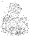
- Fig. 2 is a front view showing the internal combustion engine.
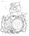
- Fig. 3 is a back view showing the internal combustion engine.
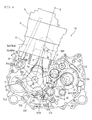
- Fig. 4 is a front view in which a front crankcase half of the internal combustion engine and others are omitted.
- Fig. 5 is a sectional view viewed along a line V-V in Fig. 4.
- Fig. 6 is a sectional view viewed along a line VI-VI in Fig. 4.
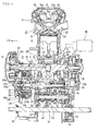
- Fig. 7 is a synthesized sectional view viewed along a line VII-VII and a line VII'-VII' in Fig. 4.
- Referring to Figs. 1 to 5, one embodiment of the invention will be described below.
Aninternal combustion engine 10 equivalent to this embodiment is a water-cooled single-cylinder 4-stroke cycle internal combustion engine and is vertically mounted in an allterrain vehicle 1 with acrankshaft 11 longitudinally directed.
The front, the rear, the right and the left are determined in a direction in which the vehicle travels forward. - The all
terrain vehicle 1 is a saddle-ride type four-wheel vehicle and a pair of right and left front wheels FW and a pair of right and left rear wheels RW respectively including a low pressure balloon tire for rough terrain are suspended in a longitudinal direction of a body frame 2. - The
internal combustion engine 10 is mounted between the front wheel FW and the rear wheel RW, anoutput shaft 61 is longitudinally protruded from atransmission 40 located on the left side of theinternal combustion engine 10, the rotational motive power of theoutput shaft 61 is transmitted to the right and left front wheels FW from a front end of theoutput shaft 61 via afront drive shaft 2F and a front finalreduction gear unit 3F, and the rotational motive power is transmitted to the right and left rear wheels RW from a rear end of the output shaft via arear drive shaft 2R and a rear finalreduction gear unit 3R. - A
front fender 4F covers the front wheel FW backward from the upside of the front wheel, arear fender 4R covers the rear wheel RW forward from the upside of the rear wheel, aside cover 5 covers the right side and the left side of theinternal combustion engine 10 mounted between the front wheel FW and the rear wheel RW, astep plate 6 is protruded outside from a lower edge of the side cover, and thestep plate 6 is laid between thefront fender 4F and therear fender 4R. - A
seat 7 is provided between the right and the leftrear fenders
The front of theside cover 5 is cut off and an opening foraccess 5a is formed.
The opening foraccess 5a reaches a rear face of thefront fender 4F and is located in a position in which the front of theinternal combustion engine 10 is revealed. - As shown in Fig. 2 which is a front view showing the
internal combustion engine 10 and in Fig. 3 which is a rear view showing it, theinternal combustion engine 10 is planted in a state in which acylinder block 13, acylinder head 14 and acylinder head cover 15 are sequentially piled on acrankcase 12 and are slightly inclined leftward (rightward in Fig. 2) based upon a traveling direction of the vehicle. - The
crankcase 12 also houses thetransmission 40 arranged on the left side of thecrankshaft 11 inside and has longitudinal structure configured by afront crankcase half 12F and arear crankcase half 12R respectively divided longitudinally by a plane perpendicular to thecrankshaft 11 directed in a longitudinal direction of the body. - Fig. 4 is a front view in which the
front crankcase half 12F of theinternal combustion engine 10 and others are omitted and shows a joined face 12Rf of therear crankcase half 12R.
Acylinder sleeve 13a is fitted to thecrankcase 12 from thecylinder block 13 and apiston 16 is fitted into thecylinder sleeve 13a so that the piston can be slid. - A connecting
rod 17 couples acrankpin 11p laid between a pair oflongitudinal crank webs crankshaft 11 and a piston pin 16p provided to thepiston 16. - As shown in Fig. 5, a
combustion chamber 20 is formed between a top face of thepiston 16 and a ceiling of thecylinder head 14 opposite to the piston, anintake port 21 is extended backward from thecombustion chamber 20, and an exhaust port 22 is extended forward. - An
intake valve 23 opens and closes an opening open to thecombustion chamber 20 of theintake port 21 and anexhaust valve 24 opens and closes an opening open to thecombustion chamber 20 of the exhaust port 22.
Rocker arms intake valve 23 and theexhaust valve 24 are provided in thecylinder head cover 15 journaling torocker arm shafts - As shown in Fig. 5, the
crankshaft 11 journalled to thefront crankcase 12F and therear crankcase 12R viamain bearings crank webs
Afront cover 30 which is an engine case cover covers thefront crankcase half 12F from the front side and is connected to the front crankcase half, and afront housing 31 is formed between the front cover and thefront crankcase half 12F.
The front end of thecrankshaft 11 extended in thefront housing 31 forward from the main bearing 18 held by thefront crankcase half 12F is rotatably supported by thefront cover 30 via bearings 19. - A
starting clutch 32 which is a power transmission control means is provided to thecrankshaft 11 in thefront housing 31 in the vicinity of the front end of the crankshaft.
The startingclutch 32 is a centrifugal clutch, a clutch inner 32i is fastened to the vicinity of the front end of thecrankshaft 11, a clutch outer 32o is supported by aprimary driving gear 33 journalled to thecrankshaft 11 via a one-way clutch in a state in which relative rotation in only one direction is allowed, and motive power is transmitted from theprimary driving gear 33 to thetransmission 40. - A driving
sprocket 34 forming a transmission mechanism for a valve that rotates acam shaft 81 described later is formed between theprimary driving gear 33 of thecrankshaft 11 and the main bearing 18.
The rear of therear crankcase half 12R is covered with arear cover 35 which is the engine case cover, arear housing 36 is formed, and analternator 37 and others are provided to thecrankshaft 11 in therear housing 36. - A
main shaft 41 of thetransmission 40 is arranged in parallel with thecrankshaft 11 on the left diagonal upside of the crankshaft 11 (see Fig. 4) and is rotatably journalled to thefront crankcase 12F and therear crankcase 12R viabearings 42, 42 (see Fig. 5).
Ashift clutch 43 is provided at the front end of themain shaft 41 extended into thefront housing 31 forward from thebearing 42 held by thefront crankcase half 12F. - The
shift clutch 43 is a multiple disc friction clutch, a clutch inner 43i is fastened to the front end of themain shaft 41, a clutch outer 43o is rotatably journalled to themain shaft 41, apressure plate 43p is interposed between the clutch inner 43i and the clutch outer 43o, thepressure plate 43p presses or releases a pile of plural clutch discs integrally rotated with the clutch outer 430 and plural friction discs integrally rotated with the clutch inner 43i, and the transmission of motive power is controlled. - A clutch operating means 46 that operates the
pressure plate 43p is arranged on the front side of themain shaft 41.
As shown in Fig. 5, as for the clutch operating means 46, a variablecam plate lever 47 is journalled to a supportingshaft 46a supported by thefront cover 30 in front coaxially with themain shaft 41 so that the variable cam plate lever can be turned and can be axially slid, aball 47b is interposed between fixing plates 47s fastened to the supportingshaft 46a opposing in front of the variablecam plate lever 47, and when the variablecam plate lever 47 is rocked, the variablecam plate lever 47 is moved backward by reaction force received from the fixing plate 47s via theball 47b. - A
coupling plate 48 connected to the variablecam plate lever 47 via abearing 48a is coupled to thepressure plate 43p of theshift clutch 43, thepressure plate 43p releases the pile of the friction discs by the backward movement of the variablecam plate lever 47, and theshift clutch 43 is let out.
Aclutch arm 49 fastened to ashift spindle 111 described later operates the variablecam plate lever 47 and aroller 49a provided to an end of theclutch arm 49 is fitted into a groove at the end of the variablecam plate lever 47. - As a primary driven
gear 45 is provided to the clutch outer 43o via adamper spring 44 and theprimary driving gear 33 and the primary drivengear 45 are engaged, the rotational motive power is transmitted to the clutch outer 43o of theshift clutch 43 via the primary drivengear 45 and thedamper spring 44 when the startingclutch 33 is let in and the rotation of thecrankshaft 11 is transmitted to theprimary driving gear 33, and when theshift clutch 43 is let in, themain shaft 41 is rotated together with the clutch inner 43i. - The starting
clutch 32 is located in front of theshift clutch 43, is arranged close to the front of theshift clutch 43 so that their clutches are partially overlapped axially (in a front view), the longitudinal length of thecrankshaft 11 is possibly shortened, distance between thecrankshaft 11 and themain shaft 41 is also reduced, and theinternal combustion engine 10 is miniaturized. - A
counter shaft 51 is arranged in parallel with themain shaft 41 on the further left side of themain shaft 41 and on the diagonal downside (see Fig. 4) and is rotatably journalled to thefront crankcase half 12F and therear crankcase half 12R viabearings 52, 52 (see Fig. 5).
As shown in Fig. 5, a speed changegear train group 53 which is the assembly of a gear train that sets a level of speed is formed between themain shaft 41 and thecounter shaft 51 and gears are selectively engaged between themain shaft 41 and thecounter shaft 51 for shift.
A reverse shaft 55 is arranged on the diagonal upside of themain shaft 41. - The
output shaft 61 is arranged on the slight right side of the downside of the counter shaft 51 (see Fig. 4) and is rotatably journalled to thefront crankcase 12F and therear crankcase 12R viabearings 62, 62 (see Fig. 5). - A
deceleration driving gear 54 is fitted on a rear end protruded into therear housing 36 backward from a crank chamber of thecounter shaft 51, a deceleration drivengear 63 fitted on theoutput shaft 61 arranged in parallel with thecounter shaft 51 is engaged with thedeceleration driving gear 54, and decelerated motive power is transmitted to theoutput shaft 61.
Theoutput shaft 61 is extended longitudinally, pierces thefront cover 30 and therear cover 35, is protruded outside, and as described above, the rotation at longitudinal both ends is respectively used for driving the front wheel FW and the rear wheel RW via thedrive shafts - A
balance shaft 71 parallel to thecrankshaft 11 is located on the slight downside of the right side (the left side in Fig. 4) of thecrankshaft 11 and as shown in Fig. 6, both ends of thebalance shaft 71 are journalled to thefront crankcase 12F and therear crankcase 12R viabearings - A
balance weight 71w formed in the center of thebalance shaft 71 is located between the front and rear crankwebs crankshaft 11, a drivengear 73b is fitted on the rear of thebalance shaft 71, and the driven gear is engaged with adriving gear 73a fitted on the crankshaft 11 (see Fig. 6).
Anoil pump 75 is provided in coaxial front of thebalance shaft 71. - A
camshaft 81 of a valve system parallel to thecrankshaft 11 is arranged on the diagonal upside of the right side of the crankshaft 11 (see Fig. 4) and both ends of thecamshaft 81 are journalled to thefront crankcase 12F and therear crankcase 12R viabearings 82, 82 (see Fig. 6). -
Cam followers cam lobes 81a, 81b of thecamshaft 81 and vertically slid receive respective lower ends ofpush rods rocker arms cylinder head cover 15. - As shown in Fig. 6, a coupling sleeve 85 provided with a driven
sprocket 86 is fitted to a front end protruded forward from thefront crankcase 12F of thecamshaft 81, a chain 87 (see a chain double-dashed line shown in Fig. 6) is wound between the drivingsprocket 34 formed on thecrankshaft 11 and the drivensprocket 86, and the rotation of thecrankshaft 11 is transmitted to thecamshaft 81 via thechain 87. - A
water pump 90 driven coaxially with thecamshaft 81 is provided to thefront cover 30 in front of thecamshaft 81.
As shown in Fig. 6, thewater pump 90 forms awater pump body 30b that connects with aclutch cover 30a covering the front of the startingclutch 32 of thefront cover 30, apump driving shaft 91 coupled to thecamshaft 81 via the coupling sleeve 85 in front of the camshaft and integrally rotated with the camshaft is fitted into thewater pump body 30b from its back, animpeller 92 is fitted to the end protruded forward of thewater pump body 30b, and awater pump cover 93 covers the front of theimpeller 92. - A starter driven
gear 96 is fitted in the rear of therear housing 36 of thecrankshaft 11 in front of the alternator 37 (see Figs. 5, 6 and 7), the rotation of a drive shaft of a startingmotor 95 protruded on the upside of the rear face of therear crankcase 12R is transmitted to the starter drivengear 96 via a speed reducing gear mechanism not shown, and thecrankshaft 11 is forcedly rotated for starting. - A
transmission driving mechanism 100 that drives thetransmission 40 is provided on the downside of thecrankshaft 11 and themain shaft 41.
As shown in Fig. 4, aguide shaft 101 is arranged substantially under themain shaft 41 in a slightly lower position than thecrankshaft 11 in parallel with themain shaft 41 and thecounter shaft 51 with both ends of the guide shaft supported by thefront crankcase 12F and therear crankcase 12R (see Fig. 7), and ashift drum 105 is rotatably laid between thefront crankcase 12F and therear crankcase 12R on the further downside of theguide shaft 101. - As shown in Fig. 7, respective shift pins of
shift forks guide shaft 101 are fitted into three shift grooves formed on the periphery of theshift drum 105, theshift fork 102a guided into the shift groove by the turning of theshift drum 105 and axially moved moves the gear on themain shaft 41, theshift forks counter shaft 51, a set of the engaged gears is changed, and shift is made. - The
shift spindle 111 which is a shift rotating shaft is arranged next to the left downside of theshift drum 105 and is located in a direction obtuse with a direction of anelectric motor 130 for shift arranged on the right side of theshift drum 105 when they are viewed from the shift drum 105 (see Fig. 4).
Theshift spindle 111 is located at the lower end of theinternal combustion engine 10 next to a lower edge of thecrankcase 12.
As shown in Fig. 7, theshift spindle 111 is long longitudinally and pierces thefront crankcase 12F, therear crankcase 12R, further, thefront cover 30 and therear cover 35. - A shift transmission means 106 is interposed between the
shift spindle 111 and theshift drum 105 and the turning of theshift spindle 111 turns theshift drum 105 via the shift transmission means 106 by a required angle.
An angle at which theshift drum 105 is turned is sensed by ashift position sensor 107 coaxially provided at the back of theshift drum 105. - The base of the
clutch arm 49 is integrally fastened to theshift spindle 111, theclutch arm 49 is integrally rocked by the turning of theshift spindle 111, rocks the variablecam plate lever 47 of theshift clutch 43 via theroller 49a at the end, and as described above, the shift clutch 43 can be let out. - As shown in Fig. 2, a
gear case 30c (see Fig. 7) is formed in the front of thefront cover 30 from a lower part of theclutch cover 30a covering the front of the startingclutch 32 of thefront cover 30 to theshift spindle 111 on the diagonal downside of the left side (the right side in Fig. 2), a speed reducinggear mechanism 120 is arranged in thegear case 30c, and is covered with agear cover 115 from the front side in thegear case 30c.
Thegear cover 115 is fastened to thegear case 30c of thefront cover 30 byplural bolts 116. - As shown in Figs. 2 and 7, a right upper half of the
gear case 30c is equivalent to the front of theclutch cover 30a of thefront cover 30 and theelectric motor 130 for the shift is attached to the front of the right upper half of thegear cover 115 covering the front of thegear case 30c from the front side.
A part ofbolt 116 out of thebolts 116 also fastens theelectric motor 130 for the shift together with thegear cover 115. - A small-
diameter driving gear 131a is formed at a rear end of amotor driving shaft 131 protruded backward from thegear cover 115 of theelectric motor 130 for the shift.
Theshift spindle 111 pierces thefront cover 30 and thegear cover 115 via sealingmaterial gear shift arm 112 is fitted onto theshift spindle 111 between thefront cover 30 and thegear cover 115.
A sectorial main part of thegear shift arm 112 is fitted onto theshift spindle 111 and a large-diameter gear 112a is formed in a peripheral circular-arc part. - As shown in Fig. 4, an
idle gear shaft 121 is journalled to thefront cover 30 and thegear cover 115 in a substantial intermediate position of themotor driving shaft 131 of the electric motor for theshift 130 and theshift spindle 111 so that both ends of the idle gear shaft can be rotated viabearings 122, 122 (see Fig. 7). - A large-
diameter gear 121a and a small-diameter gear 121b are integrally formed on theidle gear shaft 121 longitudinally.
The large-diameter gear 121a on the front side of theidle gear shaft 121 is engaged with thedriving gear 131a of themotor driving shaft 131 and the small-diameter gear 121b on the rear side is engaged with the large-diameter gear 112a of thegear shift arm 112 of theshift spindle 111. - As described above, when the
electric motor 130 for the shift is driven and the drivingshaft 131 is rotated, the rotational speed of the driving shaft is reduced via theidle gear shaft 121 and the rotational motive power is transmitted to theshift spindle 111. - As the
shift spindle 111 is arranged on the downside of the startingclutch 32 provided to the front end of thecrankshaft 11 and theelectric motor 130 for the shift is protruded in front from the lower part of thefront cover 30 covering the front of the startingclutch 32, theelectric motor 130 for the shift and theshift spindle 111 are located mutually close, and as described above, motive power can be easily and smoothly transmitted by the simple speed reducinggear mechanism 120 having oneidle gear shaft 121. - The rotation of the
shift spindle 111 lets out theshift clutch 43 via theclutch arm 49 and theclutch operating unit 46 as described above, simultaneously turns theshift drum 105 by the required angle via the shift transmission means 106, slides theshift forks gear train group 53, and a shift of thetransmission 40 is executed. - The speed reducing
gear mechanism 120 of thetransmission driving mechanism 100 is configured as described above, theidle gear shaft 121 which is a part of the speed reducinggear mechanism 120 and theelectric motor 130 for the shift are located in front of theclutch cover 30a, that is, are arranged in positions overlapped with the axial outside of the startingclutch 32. - As shown in Fig. 7, a
turning angle sensor 118 is coaxially attached to a rear end that pierces therear cover 35 of theshift spindle 111, a hexagonalfitting part 111a of the front end that pierces thefront cover 30 and thegear cover 115 of theshift spindle 111 is protruded forward, and is exposed outside. - The
fitting part 111a protruded outside of the front end of theshift spindle 111 is located in front of thefront cover 30 covering the respective fronts of the startingclutch 32 and the shift clutch 43 (see Fig. 7), theshift spindle 111 is turned by fitting anoperating part 150a having a hexagonal hole of awrench 150 which is a turning tool onto the hexagonalfitting part 111a and turning it along the front of thefront cover 30, and the shift of thetransmission 40 can be executed manually. - As shown in Fig. 1, the opening for
access 5a is formed as described above in the front of theside cover 5 of the allterrain vehicle 1 and manual shift work can be executed by inserting thewrench 150 from the opening foraccess 5a and fitting it to thefitting part 111a of theshift spindle 111 protruded in front of theinternal combustion engine 10. - When the
electric motor 130 for the shift fails, the allterrain vehicle 1 can be run by setting the speed of thetransmission 40 to first gear speed for example manually using thewrench 150 as described above. - As described above, in the
transmission driving mechanism 100, the front end of theshift spindle 111 is protruded outside and as a result, thefitting part 111a is merely formed, a special transmission driving mechanism for manual shift is not required, the number of parts is reduced, the structure is simple and is excellent in the ease of assembly, no maintenance is required, and the cost can be reduced. - As shown in Fig. 2, the
shift spindle 111 is adjacent to a lower edge of the front cover 30 (substantially a lower edge of the crankcase 12), is located on the downside between theelectric motor 130 for the shift protruded in front of thefront cover 30 and theoutput shaft 61, and thewrench 150 theoperating part 150a at the lower end of which is fitted onto thefitting part 111a at the front end of theshift spindle 111 is extended upward between theelectric motor 130 for the shift and theoutput shaft 61. - The
wrench 150 is rocked sideways along the front of thefront cover 30, its lateral turning limit position is shown by a chain double-dashed line in Fig. 2, and a sectorial area inside right and left turning limits is a turning area W. - As shown in Fig. 2, when a plane X including the crankshaft 11 (a central axis of the starting clutch 32) and (a central axis) of the
shift spindle 111 is supposed, theelectric motor 130 for the shift is arranged on the downside of the plane X, theshift clutch 43 is arranged on the other upside of the plane X, theshift clutch 43 is partially overlapped with the startingclutch 32 in the front view, and is located at the back of the startingclutch 32. - As the turning area W of the
wrench 150 is along the front of thefront cover 30 covering the respective fronts of the startingclutch 32 and theshift clutch 43 and is overlapped with a part of thefront cover 30 on the upside where theshift clutch 43 is arranged of the plane X in the front view, large space in front of the startingclutch 32 and the shift clutch 43 respective having a large diameter can be used for the turning area W of thewrench 150, thewrench 150 is lengthened, the operability can be enhanced, and work is extremely facilitated. - The
shift position detector 107 is provided to a rear end of a rotating shaft of theshift drum 105, the turningangle sensor 118 is attached to the rear end of theshift spindle 111, theshift position sensor 107 and theturning angle sensor 118 are arranged in the rear of the body of theinternal combustion engine 10, and as shown in Fig. 3, in the rear of the body of theinternal combustion engine 10, thealternator 37, the startingmotor 95 and further, accessories such as avehicle speed sensor 97 that senses vehicle speed based upon the rotation of thecounter shaft 51 are arranged. - A crankshaft
revolution number sensor 109 that senses the number of revolutions of the crankshaft based upon the rotation of the outer of thealternator 37 is attached to the rear cover 35 (see Fig. 3) and an engine speed sensor (not shown) that senses engine speed based upon the rotation of thedeceleration driving gear 54 fitted onto the rear end of thecounter shaft 51 is attached to therear cover 35.
Further, aterminal 108 of theshift position sensor 107 is protruded on the right side of thevehicle speed sensor 97, adistribution cord 99a of the alternator is extended from the upside of thealternator 37, and anAC generator terminal 99 is provided to the end. - As these accessories are arranged in the rear of the body of the
internal combustion engine 10, space is produced in front of the body of theinternal combustion engine 10 and as a result, the turning area W of thewrench 150 can be sufficiently secured. - Besides, as the accessories are concentrated on the rear of the body of the
internal combustion engine 10, a signal line and a power line respectively extended from these accessories can be collectively wired.
Further, as the accessories are arranged in the rear of the body of theinternal combustion engine 10, the accessories can be protected from a scattering stone and others. -
- 1
- All terrain vehicle,
- 10
- Internal combustion engine,
- 11
- Crankshaft,
- 12
- Crankcase,
- 30
- Front cover,
- 32
- Starting clutch,
- 37
- Alternator,
- 40
- Transmission,
- 41
- Main shaft,
- 43
- Shift clutch,
- 46
- Clutch operating means,
- 49
- Clutch arm,
- 51
- Counter shaft,
- 61
- Output shaft,
- 95
- Starting motor,
- 100
- Transmission driving mechanism,
- 101
- Guide shaft,
- 105
- Shift drum,
- 107
- Shift position sensor,
- 111
- Shift spindle,
- 115
- Gear cover,
- 118
- Turning angle sensor,
- 120
- Speed reducing gear mechanism,
- 130
- Electric motor for shift,
- 150
- Wrench.
Claims (6)
- A transmission driving mechanism of an internal combustion engine (10) comprising a transmission that shifts the rotation of a crankshaft (11) and transmits it to an output shaft (61), the transmission driving mechanism (100) rotating a shift rotating shaft by an actuator for a shift to change the speed of the transmission,
wherein one end of the shift rotating shaft pierces an engine case cover and is protruded outside, and
a fitting part onto which a turning tool is fitted is formed at the protruded end of the shift rotating shaft. - The transmission driving mechanism of the internal combustion engine (10) according to Claim 1,
wherein the internal combustion engine (10) is mounted in a vehicle with the crankshaft (11) directed in a longitudinal direction of the body,
the fitting part is formed at the front end of the shift rotating shaft parallel to the crankshaft (11) and directed in the longitudinal direction of the body, and
the turning tool an operating part of which is fitted onto the fitting part at the front end of the shift rotating shaft is turned along the front of the engine case cover. - The transmission driving mechanism of the internal combustion engine according to any of the preceding claims,
wherein a turning angle sensing means is provided to a rear end of the shift rotating shaft, and
accessories of the internal combustion engine (10) are arranged mainly in the rear of the body of the internal combustion engine (10). - The transmission driving mechanism of the internal combustion engine (10) according to any of the preceding claims,
wherein the shift rotating shaft is arranged on the downside of a starting clutch (32) provided to a front end of the crankshaft (11),
the actuator for the shift is protruded forward in a lower part of the engine case cover covering the front of the starting clutch (32), and
a turning area of the turning tool is overlapped with the starting clutch (32) on the side of the actuator for the shift of the engine case cover in a front view. - The transmission driving mechanism of the internal combustion engine (10) according to any of the preceding claims,
wherein the actuator for the shift is arranged on one side partitioned by a plane including the central axis of the starting clutch (32) and the central axis of the shift rotating shaft and a shift clutch (43) is arranged on the other side so that the shift clutch (43) is partially overlapped with the starting clutch (32) at the back of the starting clutch (32) in the front view,
the engine case cover also covers the front of the shift clutch (43) together with the front of the starting clutch, and
the turning area of the turning tool is overlapped with the shift clutch in the front view. - The transmission driving mechanism of the internal combustion engine (10) according to any of the preceding claims,
wherein the shift rotating shaft is arranged next to a lower edge of the engine case cover.
Applications Claiming Priority (1)
| Application Number | Priority Date | Filing Date | Title |
|---|---|---|---|
| JP2006138387A JP5030473B2 (en) | 2006-05-18 | 2006-05-18 | Variable speed drive mechanism for internal combustion engine |
Publications (3)
| Publication Number | Publication Date |
|---|---|
| EP1857716A2 true EP1857716A2 (en) | 2007-11-21 |
| EP1857716A3 EP1857716A3 (en) | 2008-02-27 |
| EP1857716B1 EP1857716B1 (en) | 2010-07-07 |
Family
ID=38544198
Family Applications (1)
| Application Number | Title | Priority Date | Filing Date |
|---|---|---|---|
| EP07106206A Ceased EP1857716B1 (en) | 2006-05-18 | 2007-04-16 | Transmission driving mechanism of internal combustion engine |
Country Status (6)
| Country | Link |
|---|---|
| US (1) | US8448740B2 (en) |
| EP (1) | EP1857716B1 (en) |
| JP (1) | JP5030473B2 (en) |
| AU (1) | AU2007201695B2 (en) |
| CA (1) | CA2586367C (en) |
| DE (1) | DE602007007542D1 (en) |
Cited By (4)
| Publication number | Priority date | Publication date | Assignee | Title |
|---|---|---|---|---|
| EP2372196A1 (en) * | 2010-03-30 | 2011-10-05 | Honda Motor Co., Ltd. | Transmission system for vehicle |
| WO2014189857A1 (en) * | 2013-05-20 | 2014-11-27 | Team Industries, Inc. | Shift -by-wire transmission |
| TWI500553B (en) * | 2012-11-22 | 2015-09-21 | Kwang Yang Motor Co | Engine Shift mechanism |
| EP4040021A1 (en) * | 2021-02-09 | 2022-08-10 | Kawasaki Motors, Ltd. | Vehicle |
Families Citing this family (13)
| Publication number | Priority date | Publication date | Assignee | Title |
|---|---|---|---|---|
| US7912613B2 (en) * | 2004-07-01 | 2011-03-22 | Yamaha Hatsudoki Kabushiki Kaisha | Riding type vehicle |
| JP4990004B2 (en) * | 2007-03-30 | 2012-08-01 | 本田技研工業株式会社 | Vehicle transmission |
| US8256561B2 (en) * | 2007-04-16 | 2012-09-04 | Yamaha Hatsudoki Kabushiki Kaisha | Vehicle |
| JP5091062B2 (en) * | 2008-09-02 | 2012-12-05 | 本田技研工業株式会社 | Vehicle engine |
| JP5210210B2 (en) * | 2009-03-12 | 2013-06-12 | 本田技研工業株式会社 | Power unit for vehicle |
| JP5706711B2 (en) * | 2011-02-18 | 2015-04-22 | 本田技研工業株式会社 | Vehicle with power unit |
| JP5725654B2 (en) * | 2011-03-29 | 2015-05-27 | 本田技研工業株式会社 | Vehicle shift actuator arrangement structure |
| JP6137676B2 (en) * | 2013-03-28 | 2017-05-31 | 本田技研工業株式会社 | Vehicle power unit and four-wheel vehicle |
| JP6601134B2 (en) * | 2015-10-13 | 2019-11-06 | スズキ株式会社 | 4-cycle multi-cylinder engine |
| US10982765B2 (en) | 2016-11-11 | 2021-04-20 | Team Industries, Inc. | Dual cam spring-loaded shifting transmission assembly |
| DE102019118206A1 (en) | 2018-07-06 | 2020-01-09 | Honda Motor Co., Ltd. | engine |
| JP6876660B2 (en) * | 2018-08-31 | 2021-05-26 | 本田技研工業株式会社 | Saddle-type vehicle |
| JP6779953B2 (en) * | 2018-09-27 | 2020-11-04 | 本田技研工業株式会社 | Engine superstructure of saddle-riding vehicle |
Family Cites Families (8)
| Publication number | Priority date | Publication date | Assignee | Title |
|---|---|---|---|---|
| BR9400394A (en) * | 1994-01-31 | 1995-12-05 | Equipamentos Clark Ltda | Gear shift mechanism of constantly engaged and mutually exclusive gear pairs applied to automotive or machine transmissions, automatic or manual coupling |
| CA2417066C (en) | 1997-09-12 | 2008-06-17 | Honda Giken Kogyo Kabushiki Kaisha | Power transmission device for vehicle |
| JP3853926B2 (en) * | 1997-09-12 | 2006-12-06 | 本田技研工業株式会社 | Power transmission device for vehicle |
| JP2001108093A (en) * | 1999-10-05 | 2001-04-20 | Honda Motor Co Ltd | Vehicle power transmission |
| JP2001124203A (en) * | 1999-10-22 | 2001-05-11 | Honda Motor Co Ltd | Change device for vehicle transmission |
| EP1132661B1 (en) * | 2000-03-10 | 2004-03-17 | Honda Giken Kogyo Kabushiki Kaisha | Method and apparatus for controlling gear-shift of motor-driven gear shifter |
| JP4372480B2 (en) * | 2003-08-05 | 2009-11-25 | 本田技研工業株式会社 | Change device for transmission |
| JP2005069259A (en) * | 2003-08-25 | 2005-03-17 | Yamaha Motor Co Ltd | Manual transmission device for vehicle |
-
2006
- 2006-05-18 JP JP2006138387A patent/JP5030473B2/en not_active Expired - Fee Related
-
2007
- 2007-04-16 EP EP07106206A patent/EP1857716B1/en not_active Ceased
- 2007-04-16 DE DE602007007542T patent/DE602007007542D1/en active Active
- 2007-04-17 AU AU2007201695A patent/AU2007201695B2/en not_active Ceased
- 2007-04-25 CA CA2586367A patent/CA2586367C/en not_active Expired - Fee Related
- 2007-05-16 US US11/804,057 patent/US8448740B2/en active Active
Cited By (8)
| Publication number | Priority date | Publication date | Assignee | Title |
|---|---|---|---|---|
| EP2372196A1 (en) * | 2010-03-30 | 2011-10-05 | Honda Motor Co., Ltd. | Transmission system for vehicle |
| US8720292B2 (en) | 2010-03-30 | 2014-05-13 | Honda Motor Co., Ltd. | Transmission system for vehicle |
| TWI500553B (en) * | 2012-11-22 | 2015-09-21 | Kwang Yang Motor Co | Engine Shift mechanism |
| WO2014189857A1 (en) * | 2013-05-20 | 2014-11-27 | Team Industries, Inc. | Shift -by-wire transmission |
| US9316311B2 (en) | 2013-05-20 | 2016-04-19 | Team Industries, Inc. | Method and apparatus for controlling a shift-by-wire transmission |
| US9528603B2 (en) | 2013-05-20 | 2016-12-27 | Team Industries, Inc. | Shift-by-wire transmission |
| EP4040021A1 (en) * | 2021-02-09 | 2022-08-10 | Kawasaki Motors, Ltd. | Vehicle |
| US12202567B2 (en) | 2021-02-09 | 2025-01-21 | Kawasaki Motors, Ltd. | Vehicle |
Also Published As
| Publication number | Publication date |
|---|---|
| JP2007309404A (en) | 2007-11-29 |
| JP5030473B2 (en) | 2012-09-19 |
| CA2586367C (en) | 2010-12-14 |
| CA2586367A1 (en) | 2007-11-18 |
| US20070267240A1 (en) | 2007-11-22 |
| US8448740B2 (en) | 2013-05-28 |
| DE602007007542D1 (en) | 2010-08-19 |
| EP1857716A3 (en) | 2008-02-27 |
| AU2007201695B2 (en) | 2010-02-11 |
| AU2007201695A1 (en) | 2007-12-06 |
| EP1857716B1 (en) | 2010-07-07 |
Similar Documents
| Publication | Publication Date | Title |
|---|---|---|
| EP1857716B1 (en) | Transmission driving mechanism of internal combustion engine | |
| JP5468439B2 (en) | Vehicle transmission | |
| JP6069774B2 (en) | Power unit for vehicle | |
| US10544863B2 (en) | Transmission for vehicle and engine | |
| US11293527B2 (en) | Vehicle power unit | |
| CN101178026A (en) | power unit | |
| JP5013815B2 (en) | Power unit for vehicle | |
| JP6160063B2 (en) | Gear shift device for transmission | |
| JP4294378B2 (en) | Motorcycle | |
| EP1666721B1 (en) | Internal combustion engine | |
| TWI490404B (en) | Engine, straddle type vehicle, and engine assembly method | |
| EP2857706B1 (en) | Straddle-type vehicle | |
| JP4684975B2 (en) | Power transmission device | |
| JP4878853B2 (en) | Internal combustion engine | |
| US8857285B2 (en) | Saddle type vehicle and vehicle power unit | |
| EP1112920B1 (en) | Transmission means and motor vehicle | |
| JP7559575B2 (en) | engine | |
| JP6800263B2 (en) | Transmission of saddle-type vehicle | |
| US11932346B2 (en) | Saddle-type vehicle | |
| JPWO2017135320A1 (en) | Engine unit | |
| JP4508306B2 (en) | Power unit for vehicle | |
| JP2007100749A (en) | Assembly structure of power transmission mechanism |
Legal Events
| Date | Code | Title | Description |
|---|---|---|---|
| PUAI | Public reference made under article 153(3) epc to a published international application that has entered the european phase |
Free format text: ORIGINAL CODE: 0009012 |
|
| 17P | Request for examination filed |
Effective date: 20070416 |
|
| AK | Designated contracting states |
Kind code of ref document: A2 Designated state(s): AT BE BG CH CY CZ DE DK EE ES FI FR GB GR HU IE IS IT LI LT LU LV MC MT NL PL PT RO SE SI SK TR |
|
| AX | Request for extension of the european patent |
Extension state: AL BA HR MK YU |
|
| PUAL | Search report despatched |
Free format text: ORIGINAL CODE: 0009013 |
|
| AK | Designated contracting states |
Kind code of ref document: A3 Designated state(s): AT BE BG CH CY CZ DE DK EE ES FI FR GB GR HU IE IS IT LI LT LU LV MC MT NL PL PT RO SE SI SK TR |
|
| AX | Request for extension of the european patent |
Extension state: AL BA HR MK YU |
|
| AKX | Designation fees paid |
Designated state(s): DE FR GB |
|
| GRAP | Despatch of communication of intention to grant a patent |
Free format text: ORIGINAL CODE: EPIDOSNIGR1 |
|
| GRAS | Grant fee paid |
Free format text: ORIGINAL CODE: EPIDOSNIGR3 |
|
| GRAA | (expected) grant |
Free format text: ORIGINAL CODE: 0009210 |
|
| AK | Designated contracting states |
Kind code of ref document: B1 Designated state(s): DE FR GB |
|
| REG | Reference to a national code |
Ref country code: GB Ref legal event code: FG4D |
|
| REF | Corresponds to: |
Ref document number: 602007007542 Country of ref document: DE Date of ref document: 20100819 Kind code of ref document: P |
|
| PLBE | No opposition filed within time limit |
Free format text: ORIGINAL CODE: 0009261 |
|
| STAA | Information on the status of an ep patent application or granted ep patent |
Free format text: STATUS: NO OPPOSITION FILED WITHIN TIME LIMIT |
|
| 26N | No opposition filed |
Effective date: 20110408 |
|
| REG | Reference to a national code |
Ref country code: DE Ref legal event code: R097 Ref document number: 602007007542 Country of ref document: DE Effective date: 20110408 |
|
| REG | Reference to a national code |
Ref country code: GB Ref legal event code: 746 Effective date: 20140128 |
|
| REG | Reference to a national code |
Ref country code: DE Ref legal event code: R084 Ref document number: 602007007542 Country of ref document: DE Effective date: 20140204 |
|
| REG | Reference to a national code |
Ref country code: FR Ref legal event code: PLFP Year of fee payment: 10 |
|
| REG | Reference to a national code |
Ref country code: FR Ref legal event code: PLFP Year of fee payment: 11 |
|
| REG | Reference to a national code |
Ref country code: FR Ref legal event code: PLFP Year of fee payment: 12 |
|
| PGFP | Annual fee paid to national office [announced via postgrant information from national office to epo] |
Ref country code: GB Payment date: 20180329 Year of fee payment: 12 |
|
| PGFP | Annual fee paid to national office [announced via postgrant information from national office to epo] |
Ref country code: FR Payment date: 20180315 Year of fee payment: 12 |
|
| PGFP | Annual fee paid to national office [announced via postgrant information from national office to epo] |
Ref country code: DE Payment date: 20190402 Year of fee payment: 13 |
|
| GBPC | Gb: european patent ceased through non-payment of renewal fee |
Effective date: 20190416 |
|
| PG25 | Lapsed in a contracting state [announced via postgrant information from national office to epo] |
Ref country code: GB Free format text: LAPSE BECAUSE OF NON-PAYMENT OF DUE FEES Effective date: 20190416 |
|
| PG25 | Lapsed in a contracting state [announced via postgrant information from national office to epo] |
Ref country code: FR Free format text: LAPSE BECAUSE OF NON-PAYMENT OF DUE FEES Effective date: 20190430 |
|
| REG | Reference to a national code |
Ref country code: DE Ref legal event code: R119 Ref document number: 602007007542 Country of ref document: DE |
|
| PG25 | Lapsed in a contracting state [announced via postgrant information from national office to epo] |
Ref country code: DE Free format text: LAPSE BECAUSE OF NON-PAYMENT OF DUE FEES Effective date: 20201103 |