EP1857648A1 - System and methods for improving emission control of internal combustion engines - Google Patents
System and methods for improving emission control of internal combustion engines Download PDFInfo
- Publication number
- EP1857648A1 EP1857648A1 EP07015943A EP07015943A EP1857648A1 EP 1857648 A1 EP1857648 A1 EP 1857648A1 EP 07015943 A EP07015943 A EP 07015943A EP 07015943 A EP07015943 A EP 07015943A EP 1857648 A1 EP1857648 A1 EP 1857648A1
- Authority
- EP
- European Patent Office
- Prior art keywords
- fuel
- catalyst
- fuel processor
- nsr
- exhaust
- Prior art date
- Legal status (The legal status is an assumption and is not a legal conclusion. Google has not performed a legal analysis and makes no representation as to the accuracy of the status listed.)
- Granted
Links
Images


Classifications
-
- B—PERFORMING OPERATIONS; TRANSPORTING
- B01—PHYSICAL OR CHEMICAL PROCESSES OR APPARATUS IN GENERAL
- B01D—SEPARATION
- B01D53/00—Separation of gases or vapours; Recovering vapours of volatile solvents from gases; Chemical or biological purification of waste gases, e.g. engine exhaust gases, smoke, fumes, flue gases, aerosols
- B01D53/34—Chemical or biological purification of waste gases
- B01D53/92—Chemical or biological purification of waste gases of engine exhaust gases
- B01D53/94—Chemical or biological purification of waste gases of engine exhaust gases by catalytic processes
- B01D53/9404—Removing only nitrogen compounds
- B01D53/9409—Nitrogen oxides
- B01D53/9431—Processes characterised by a specific device
-
- F—MECHANICAL ENGINEERING; LIGHTING; HEATING; WEAPONS; BLASTING
- F01—MACHINES OR ENGINES IN GENERAL; ENGINE PLANTS IN GENERAL; STEAM ENGINES
- F01N—GAS-FLOW SILENCERS OR EXHAUST APPARATUS FOR MACHINES OR ENGINES IN GENERAL; GAS-FLOW SILENCERS OR EXHAUST APPARATUS FOR INTERNAL COMBUSTION ENGINES
- F01N13/00—Exhaust or silencing apparatus characterised by constructional features ; Exhaust or silencing apparatus, or parts thereof, having pertinent characteristics not provided for in, or of interest apart from, groups F01N1/00 - F01N5/00, F01N9/00, F01N11/00
- F01N13/009—Exhaust or silencing apparatus characterised by constructional features ; Exhaust or silencing apparatus, or parts thereof, having pertinent characteristics not provided for in, or of interest apart from, groups F01N1/00 - F01N5/00, F01N9/00, F01N11/00 having two or more separate purifying devices arranged in series
- F01N13/0093—Exhaust or silencing apparatus characterised by constructional features ; Exhaust or silencing apparatus, or parts thereof, having pertinent characteristics not provided for in, or of interest apart from, groups F01N1/00 - F01N5/00, F01N9/00, F01N11/00 having two or more separate purifying devices arranged in series the purifying devices are of the same type
-
- F—MECHANICAL ENGINEERING; LIGHTING; HEATING; WEAPONS; BLASTING
- F01—MACHINES OR ENGINES IN GENERAL; ENGINE PLANTS IN GENERAL; STEAM ENGINES
- F01N—GAS-FLOW SILENCERS OR EXHAUST APPARATUS FOR MACHINES OR ENGINES IN GENERAL; GAS-FLOW SILENCERS OR EXHAUST APPARATUS FOR INTERNAL COMBUSTION ENGINES
- F01N3/00—Exhaust or silencing apparatus having means for purifying, rendering innocuous, or otherwise treating exhaust
- F01N3/08—Exhaust or silencing apparatus having means for purifying, rendering innocuous, or otherwise treating exhaust for rendering innocuous
- F01N3/0807—Exhaust or silencing apparatus having means for purifying, rendering innocuous, or otherwise treating exhaust for rendering innocuous by using absorbents or adsorbents
- F01N3/0814—Exhaust or silencing apparatus having means for purifying, rendering innocuous, or otherwise treating exhaust for rendering innocuous by using absorbents or adsorbents combined with catalytic converters, e.g. NOx absorption/storage reduction catalysts
-
- F—MECHANICAL ENGINEERING; LIGHTING; HEATING; WEAPONS; BLASTING
- F01—MACHINES OR ENGINES IN GENERAL; ENGINE PLANTS IN GENERAL; STEAM ENGINES
- F01N—GAS-FLOW SILENCERS OR EXHAUST APPARATUS FOR MACHINES OR ENGINES IN GENERAL; GAS-FLOW SILENCERS OR EXHAUST APPARATUS FOR INTERNAL COMBUSTION ENGINES
- F01N3/00—Exhaust or silencing apparatus having means for purifying, rendering innocuous, or otherwise treating exhaust
- F01N3/08—Exhaust or silencing apparatus having means for purifying, rendering innocuous, or otherwise treating exhaust for rendering innocuous
- F01N3/0807—Exhaust or silencing apparatus having means for purifying, rendering innocuous, or otherwise treating exhaust for rendering innocuous by using absorbents or adsorbents
- F01N3/0821—Exhaust or silencing apparatus having means for purifying, rendering innocuous, or otherwise treating exhaust for rendering innocuous by using absorbents or adsorbents combined with particulate filters
-
- F—MECHANICAL ENGINEERING; LIGHTING; HEATING; WEAPONS; BLASTING
- F01—MACHINES OR ENGINES IN GENERAL; ENGINE PLANTS IN GENERAL; STEAM ENGINES
- F01N—GAS-FLOW SILENCERS OR EXHAUST APPARATUS FOR MACHINES OR ENGINES IN GENERAL; GAS-FLOW SILENCERS OR EXHAUST APPARATUS FOR INTERNAL COMBUSTION ENGINES
- F01N3/00—Exhaust or silencing apparatus having means for purifying, rendering innocuous, or otherwise treating exhaust
- F01N3/08—Exhaust or silencing apparatus having means for purifying, rendering innocuous, or otherwise treating exhaust for rendering innocuous
- F01N3/0807—Exhaust or silencing apparatus having means for purifying, rendering innocuous, or otherwise treating exhaust for rendering innocuous by using absorbents or adsorbents
- F01N3/0828—Exhaust or silencing apparatus having means for purifying, rendering innocuous, or otherwise treating exhaust for rendering innocuous by using absorbents or adsorbents characterised by the absorbed or adsorbed substances
- F01N3/0842—Nitrogen oxides
-
- F—MECHANICAL ENGINEERING; LIGHTING; HEATING; WEAPONS; BLASTING
- F01—MACHINES OR ENGINES IN GENERAL; ENGINE PLANTS IN GENERAL; STEAM ENGINES
- F01N—GAS-FLOW SILENCERS OR EXHAUST APPARATUS FOR MACHINES OR ENGINES IN GENERAL; GAS-FLOW SILENCERS OR EXHAUST APPARATUS FOR INTERNAL COMBUSTION ENGINES
- F01N3/00—Exhaust or silencing apparatus having means for purifying, rendering innocuous, or otherwise treating exhaust
- F01N3/08—Exhaust or silencing apparatus having means for purifying, rendering innocuous, or otherwise treating exhaust for rendering innocuous
- F01N3/0807—Exhaust or silencing apparatus having means for purifying, rendering innocuous, or otherwise treating exhaust for rendering innocuous by using absorbents or adsorbents
- F01N3/0871—Regulation of absorbents or adsorbents, e.g. purging
-
- F—MECHANICAL ENGINEERING; LIGHTING; HEATING; WEAPONS; BLASTING
- F01—MACHINES OR ENGINES IN GENERAL; ENGINE PLANTS IN GENERAL; STEAM ENGINES
- F01N—GAS-FLOW SILENCERS OR EXHAUST APPARATUS FOR MACHINES OR ENGINES IN GENERAL; GAS-FLOW SILENCERS OR EXHAUST APPARATUS FOR INTERNAL COMBUSTION ENGINES
- F01N3/00—Exhaust or silencing apparatus having means for purifying, rendering innocuous, or otherwise treating exhaust
- F01N3/08—Exhaust or silencing apparatus having means for purifying, rendering innocuous, or otherwise treating exhaust for rendering innocuous
- F01N3/10—Exhaust or silencing apparatus having means for purifying, rendering innocuous, or otherwise treating exhaust for rendering innocuous by thermal or catalytic conversion of noxious components of exhaust
- F01N3/24—Exhaust or silencing apparatus having means for purifying, rendering innocuous, or otherwise treating exhaust for rendering innocuous by thermal or catalytic conversion of noxious components of exhaust characterised by constructional aspects of converting apparatus
- F01N3/28—Construction of catalytic reactors
- F01N3/2882—Catalytic reactors combined or associated with other devices, e.g. exhaust silencers or other exhaust purification devices
-
- F—MECHANICAL ENGINEERING; LIGHTING; HEATING; WEAPONS; BLASTING
- F01—MACHINES OR ENGINES IN GENERAL; ENGINE PLANTS IN GENERAL; STEAM ENGINES
- F01N—GAS-FLOW SILENCERS OR EXHAUST APPARATUS FOR MACHINES OR ENGINES IN GENERAL; GAS-FLOW SILENCERS OR EXHAUST APPARATUS FOR INTERNAL COMBUSTION ENGINES
- F01N3/00—Exhaust or silencing apparatus having means for purifying, rendering innocuous, or otherwise treating exhaust
- F01N3/08—Exhaust or silencing apparatus having means for purifying, rendering innocuous, or otherwise treating exhaust for rendering innocuous
- F01N3/10—Exhaust or silencing apparatus having means for purifying, rendering innocuous, or otherwise treating exhaust for rendering innocuous by thermal or catalytic conversion of noxious components of exhaust
- F01N3/24—Exhaust or silencing apparatus having means for purifying, rendering innocuous, or otherwise treating exhaust for rendering innocuous by thermal or catalytic conversion of noxious components of exhaust characterised by constructional aspects of converting apparatus
- F01N3/28—Construction of catalytic reactors
- F01N3/2892—Exhaust flow directors or the like, e.g. upstream of catalytic device
-
- F—MECHANICAL ENGINEERING; LIGHTING; HEATING; WEAPONS; BLASTING
- F01—MACHINES OR ENGINES IN GENERAL; ENGINE PLANTS IN GENERAL; STEAM ENGINES
- F01N—GAS-FLOW SILENCERS OR EXHAUST APPARATUS FOR MACHINES OR ENGINES IN GENERAL; GAS-FLOW SILENCERS OR EXHAUST APPARATUS FOR INTERNAL COMBUSTION ENGINES
- F01N2240/00—Combination or association of two or more different exhaust treating devices, or of at least one such device with an auxiliary device, not covered by indexing codes F01N2230/00 or F01N2250/00, one of the devices being
- F01N2240/20—Combination or association of two or more different exhaust treating devices, or of at least one such device with an auxiliary device, not covered by indexing codes F01N2230/00 or F01N2250/00, one of the devices being a flow director or deflector
-
- F—MECHANICAL ENGINEERING; LIGHTING; HEATING; WEAPONS; BLASTING
- F01—MACHINES OR ENGINES IN GENERAL; ENGINE PLANTS IN GENERAL; STEAM ENGINES
- F01N—GAS-FLOW SILENCERS OR EXHAUST APPARATUS FOR MACHINES OR ENGINES IN GENERAL; GAS-FLOW SILENCERS OR EXHAUST APPARATUS FOR INTERNAL COMBUSTION ENGINES
- F01N2240/00—Combination or association of two or more different exhaust treating devices, or of at least one such device with an auxiliary device, not covered by indexing codes F01N2230/00 or F01N2250/00, one of the devices being
- F01N2240/30—Combination or association of two or more different exhaust treating devices, or of at least one such device with an auxiliary device, not covered by indexing codes F01N2230/00 or F01N2250/00, one of the devices being a fuel reformer
-
- F—MECHANICAL ENGINEERING; LIGHTING; HEATING; WEAPONS; BLASTING
- F01—MACHINES OR ENGINES IN GENERAL; ENGINE PLANTS IN GENERAL; STEAM ENGINES
- F01N—GAS-FLOW SILENCERS OR EXHAUST APPARATUS FOR MACHINES OR ENGINES IN GENERAL; GAS-FLOW SILENCERS OR EXHAUST APPARATUS FOR INTERNAL COMBUSTION ENGINES
- F01N2610/00—Adding substances to exhaust gases
- F01N2610/03—Adding substances to exhaust gases the substance being hydrocarbons, e.g. engine fuel
-
- F—MECHANICAL ENGINEERING; LIGHTING; HEATING; WEAPONS; BLASTING
- F01—MACHINES OR ENGINES IN GENERAL; ENGINE PLANTS IN GENERAL; STEAM ENGINES
- F01N—GAS-FLOW SILENCERS OR EXHAUST APPARATUS FOR MACHINES OR ENGINES IN GENERAL; GAS-FLOW SILENCERS OR EXHAUST APPARATUS FOR INTERNAL COMBUSTION ENGINES
- F01N2610/00—Adding substances to exhaust gases
- F01N2610/04—Adding substances to exhaust gases the substance being hydrogen
-
- F—MECHANICAL ENGINEERING; LIGHTING; HEATING; WEAPONS; BLASTING
- F01—MACHINES OR ENGINES IN GENERAL; ENGINE PLANTS IN GENERAL; STEAM ENGINES
- F01N—GAS-FLOW SILENCERS OR EXHAUST APPARATUS FOR MACHINES OR ENGINES IN GENERAL; GAS-FLOW SILENCERS OR EXHAUST APPARATUS FOR INTERNAL COMBUSTION ENGINES
- F01N2610/00—Adding substances to exhaust gases
- F01N2610/10—Adding substances to exhaust gases the substance being heated, e.g. by heating tank or supply line of the added substance
-
- F—MECHANICAL ENGINEERING; LIGHTING; HEATING; WEAPONS; BLASTING
- F02—COMBUSTION ENGINES; HOT-GAS OR COMBUSTION-PRODUCT ENGINE PLANTS
- F02D—CONTROLLING COMBUSTION ENGINES
- F02D41/00—Electrical control of supply of combustible mixture or its constituents
- F02D41/0002—Controlling intake air
-
- F—MECHANICAL ENGINEERING; LIGHTING; HEATING; WEAPONS; BLASTING
- F02—COMBUSTION ENGINES; HOT-GAS OR COMBUSTION-PRODUCT ENGINE PLANTS
- F02D—CONTROLLING COMBUSTION ENGINES
- F02D41/00—Electrical control of supply of combustible mixture or its constituents
- F02D41/0025—Controlling engines characterised by use of non-liquid fuels, pluralities of fuels, or non-fuel substances added to the combustible mixtures
- F02D41/0047—Controlling exhaust gas recirculation [EGR]
- F02D41/005—Controlling exhaust gas recirculation [EGR] according to engine operating conditions
- F02D41/0055—Special engine operating conditions, e.g. for regeneration of exhaust gas treatment apparatus
-
- F—MECHANICAL ENGINEERING; LIGHTING; HEATING; WEAPONS; BLASTING
- F02—COMBUSTION ENGINES; HOT-GAS OR COMBUSTION-PRODUCT ENGINE PLANTS
- F02D—CONTROLLING COMBUSTION ENGINES
- F02D41/00—Electrical control of supply of combustible mixture or its constituents
- F02D41/02—Circuit arrangements for generating control signals
- F02D41/021—Introducing corrections for particular conditions exterior to the engine
- F02D41/0235—Introducing corrections for particular conditions exterior to the engine in relation with the state of the exhaust gas treating apparatus
- F02D41/027—Introducing corrections for particular conditions exterior to the engine in relation with the state of the exhaust gas treating apparatus to purge or regenerate the exhaust gas treating apparatus
- F02D41/0275—Introducing corrections for particular conditions exterior to the engine in relation with the state of the exhaust gas treating apparatus to purge or regenerate the exhaust gas treating apparatus the exhaust gas treating apparatus being a NOx trap or adsorbent
Definitions
- This invention relates generally to internal combustion (“IC”) engines, and more particularly, to devices, systems, and methods for improving the performance and emission control of IC engines that produce nitrogen oxides (“NO x ”) emissions. It further relates generally to emission control systems, catalytic reaction systems, and fuel processing.
- IC internal combustion
- NO x nitrogen oxides
- Lean-burn engines include both spark-ignition (“SI”) and compression-ignition (“CI”) engines. In comparison to conventional SI engines, lean-burn SI engines offer 20-25% greater fuel economy, while CI engines offer 50-100% greater fuel economy. CI engines are widely used throughout the United States in heavy-duty vehicles and their use in light-duty vehicles is expected to grow. CI engines are also widely used throughout much of the world in passenger vehicles, light and heavy-duty trucks, and electric power generators.
- SI spark-ignition
- CI compression-ignition
- NSR NO x storage-reduction
- a typical NSR catalyst has an adsorbent-catalyst system, providing the dual functions of reversible NO x storage or trapping, and NO x reduction.
- One component of the NSR catalyst reacts with NO x in the gas stream to capture it under oxidizing conditions or conditions where the exhaust stream contains excess O 2 . This component is selected so that when the exhaust stream is made reducing, that is, containing excess reducing species, the NO x is released.
- the NSR catalyst also contains a NO x reduction catalyst that reacts NO x with a reducing agent under reducing conditions to form non-polluting N 2 .
- N 2 When the exhaust stream is made reducing, the NO x is released and this NO x reacts with the reducing species on the NO x reduction catalyst to form N 2 .
- adsorbent-catalyst system is the Pt/Rh/Ba/TiO 2 /ZrO 2 / ⁇ -Al 2 O 3 system, which has been used commercially in vehicles in Japan.
- NSR catalyst Main advantages of the NSR catalyst are its compatibility and effectiveness with fuel-efficient lean-burn IC engines; its commercial acceptance; its unneeded use of ammonia or urea as reducing agents; and its ability to obtain high NO x conversions when operated at ideal conditions. For example, NO x conversions of 90 to 100% have been achieved in tests of diesel engines under ideal conditions using diesel fuel as a reducing agent.
- NSR technology has some serious disadvantages and limitations as well.
- the environment of the NSR catalyst must be made rich to convert the trapped NO x to N 2 and to regenerate the catalyst. If the reducing environment in the exhaust were to be obtained by modifying the engine operation from lean to rich, then the engine cycle would be operating in a region where it was not designed to operate. For example a diesel engine, which usually operates without a throttle on the air intake, would now require a throttle to drive the air/fuel ratio into the rich regime. In addition, this would have to be done quickly and quite frequently, from about every 2 to 20 minutes.
- Fuel may be injected into the exhaust stream and combusted on the NSR catalyst or on an upstream oxidation catalyst in order to both consume the oxygen and to produce the reducing environment.
- This has been shown to give reasonable regeneration cycles and NO x conversion efficiency.
- this procedure does not work well since the catalyst is not sufficiently reactive with diesel fuel.
- the high temperatures produced could drive the NSR catalyst to an undesirably high temperature.
- NSR adsorbents are typically very sensitive to sulfur.
- the NO x adsorbent material can react with sulfur oxides contained in the fuel to form sulfates, as described for example in S. Matsumoto, CATTECH, Vol. 4, No. 2, pp. 102-109,2000 ; K. Yamazaki et al., Applied Catalysis B: Environmental, Vol. 30, Nos. 3 and 4, pp. 459-468, 2001 and the references cited therein, all of which are hereby incorporated by reference in their entirety.
- These sulfates are not readily decomposed and slowly convert the NO x adsorbent to an inactive sulfate, reducing its trapping efficiency.
- the NSR catalyst Even with low sulfur fuel (e.g., in the range of 15ppm) the NSR catalyst only lasts for about 500 to 1000 vehicle miles before its NO x trapping efficiency becomes significantly reduced. To produce a NSR catalyst that would last the 150,000 to 400,000 miles required by current and foreseeable emissions regulations, the NSR unit would have to be designed much too large to be conveniently utilized within the industry. While it has been found that the NSR catalyst unit can be desulfated by treatment in a reducing atmosphere at temperatures of 500-650°C, it is very difficult to operate an engine in a manner so as to produce this environment within the NSR trap unit itself.
- the processor is limited to producing the reducing agents, it does not aid in reducing the oxygen level in the exhaust.
- this device cannot provide a high enough exhaust temperature to facilitate either optimum NSR catalyst regeneration, or desulfation.
- the fuel and air must be operated intermittently. This may be very difficult since the fuel processor must be maintained at elevated temperatures to function properly. During idle or low load operation, the NSR catalyst may be regenerated only once every 10 to 20 minutes for optimum fuel economy.
- the fuel processor must be maintained at elevated temperatures for very long periods, even when not needed, energy expenditure is significantly increased and fuel economy is adversely affected.
- the present invention fills this need by providing systems and processes that enable NSR technology. In this way, large-scale commercial use of diesel and other lean-burn engines with NSR technologies is facilitated. This in turn helps to conserve petroleum and to reduce greenhouse gas emissions while ensuring compliance with strict environmental regulations.
- the present invention fulfills these objects by providing a system for reducing NO x in an exhaust stream containing excess oxygen comprising, a NSR catalyst, a fuel processor, and at least one fuel injector port.
- the fuel processor is located at a position upstream of the NSR catalyst and comprises an inlet, an outlet, and at least one catalyst. Fuel is injected into the fuel injection port and reacts on the fuel processor catalyst to rapidly increase the temperature of at least a portion of the fuel processor catalyst and at least a portion of it is converted to H 2 and CO.
- the system further comprises a thermal mass having a heat capacity greater than that of the fuel processor.
- the thermal mass may for example be a PM filter, a monolithic structure, or may be a portion of the NSR catalyst or fuel processor.
- the system may optionally comprise a fuel preheater, a fuel vaporizer, a mixer, and a control system.
- the present invention fulfills these objects by providing a method for regenerating an NSR catalyst adsorbent comprising the steps of providing an exhaust stream from an engine, injecting fuel into a position upstream of a fuel processor, optionally mixing the exhaust stream with the fuel, reacting the fuel and exhaust stream mixture within the fuel processor to generate a reducing gas mixture comprising CO and H 2 , and introducing the reducing gas mixture into a NO x trap, whereby the adsorbent is regenerated by introduction of the reducing gas mixture.
- the fuel is vaporized prior to injection.
- the fuel is injected at an equivalence ratio greater than 1.
- the fuel may be either gasoline or diesel fuel.
- at least a portion of the catalyst is heated to at least 500°C.
- the present invention fulfills these objects by providing a fuel processor unit for use with a NSR system comprising an inlet, an outlet, at least one catalyst, and at least one fuel injection port.
- the fuel injection port is located at a position upstream of the catalyst and facilitates the injection of fuel into the catalyst. At least a portion of the fuel reacts on the catalyst to rapidly raise the temperature oaf at least a portion of the catalyst, and at least a portion of the fuel is converted to H 2 and CO.
- the fuel processor unit further comprises a mixer or additional catalysts.
- the present invention provides control strategies for use with the systems and methods of the present invention.
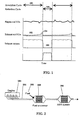
- FIG. 1 depicts NO x adsorption and reduction in an illustrative NSR system.
- FIG. 2 illustrates one variation of the system of the present invention wherein a fuel processor is located upstream of a NSR system.
- FIG. 3 illustrates one variation of the fuel processor of the present invention, wherein the fuel processor comprises a single catalyst.
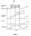
- FIG. 4 provides a time-based graph illustrating one method of operating the fuel processor in accordance with the present invention.
- FIG. 5 illustrates one variation of the present invention wherein the fuel processor comprises two catalysts in series.
- FIG. 6 illustrates one variation of the present invention wherein the fuel processor comprises two catalysts in parallel.
- FIG. 7 provides an illustrative set of thermal response curves for fuel processors having different thermal masses.
- FIG. 8 provides test results indicating rapid heat up and generation of H 2 using the present invention.
- FIG. 9 provides test results indicating rapid heat up and generation of H 2 using the present invention with an alternative fuel and engine schedule.
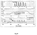
- FIG. 10 provides test results using one possible desulfation scheme using the fuel processor of the present invention.
- FIG. 11 provides test results indicating rapid heat up and generation of H 2 and CO using the present invention with a system containing a thermal mass downstream of the fuel processor.
- the present invention provides a system for improving the performance and emission control of IC engines, and in particular, lean-burn engines equipped with a NSR catalyst.
- NSR catalyst When reference is made herein to a "NSR catalyst,” it should be understood that all systems having a NO x adsorbent-catalyst system are embodied thereunder.
- FIG.1 the operation of a typical NSR catalyst.
- the NSR catalyst may be designed so that the adsorption is very efficient, with nearly complete adsorption of NO x from the exhaust stream, as shown by curve 102.
- the NSR catalyst typically comprises a canister situated in the exhaust unit to enable the exhaust gas to flow therethrough.
- Typical catalysts are honeycomb like, monolithic structures having the adsorbent and catalyst components coated onto their surfaces or walls.
- the adsorbent in the NSR catalyst becomes saturated with NO x , the adsorption becomes less complete and the NO x level exiting the NO x trap begins to increase as shown by curve 104.
- the composition of the exhaust stream is changed from an oxidizing to a reducing state, and reduction cycle 106 begins.
- a reducing agent is then introduced and the oxygen level is reduced to zero as shown by curve 108.
- the NO x is desorbed from the adsorbent and is reduced to nitrogen by the catalytic components of the NO x trap.
- This reaction generally occurs with sufficient speed so that reduction cycle 106 is relatively short while at the same time permits sufficient time to elapse so that a significant fraction of the NO x adsorption capacity is regenerated.
- the exhaust composition then reverts back to its normal oxidizing condition, and the entire cycle is repeated.
- adsorption cycle 100 lasts anywhere from 1 to 5 minutes at high load and possibly 20 minutes at low load or idle.
- Regeneration-reduction cycle 106 typically lasts 1 to 10 seconds and possibly longer depending on the time required to regenerate the NSR catalyst.
- the reducing gas composition for regeneration-reduction is obtained by injection of extra fuel into either the engine cylinders late in combustion (i.e., during the end of the power stroke or during the exhaust stroke), or directly into the exhaust pipe upstream of the NSR system.
- the overall NO x conversion or removal performance of this technology is affected by the regeneration-reduction performance of the adsorbent-catalyst system. Thus, if the regeneration cycle is ineffective, the subsequent adsorption cycle is inefficient and the NO x levels exiting the exhaust are typically very high.
- fuel processor 200 may be located at a position along exhaust pipe 202 at a distance between engine 204 and NSR system 206. In this way, the exhaust stream will flow first through fuel processor 200 and then through NSR system 206.
- Fuel processor 200 may be located together with NSR system 206 in a single housing structure, or it may not be. In one variation, as will be described in more detail below, fuel processor 200 is operated intermittently to periodically regenerate the NSR adsorbent of the NSR system 206. When regenerating the NSR adsorbent, fuel 208 may be injected into fuel processor 200, injected at a position upstream of fuel processor 200, or may be injected directly into both fuel processor unit 200 and at a position upstream thereof.
- fuel processor 200 comprises at least one catalyst, as shown in FIG. 3. As illustratively shown therein, fuel processor 200 comprises inlet 300, outlet 302, and at least one catalyst 308. At least one fuel injection port 304 and an optional mixer 306 are located at a position upstream of the fuel processor. In addition, fuel processor 200 may further comprise a fuel preheater, fuel vaporizer, a secondary injection port for the introduction of air or additional fuel (not shown), and a control system (not shown).
- fuel processor 200 comprises inlet 300 for receiving exhaust gas mixture 310.
- Fuel injection port 304 is located at a position upstream of fuel processor 200 for receiving fuel therein. After the fuel is injected into port 304, it enters fuel processor 200 and combines with exhaust gas mixture 310.
- the fuel to be injected into port 304 may take the form of a vapor, a liquid, or a combination of the two. If the injected fuel is a liquid, then some or all of it may be vaporized when contacted by the hot exhaust gas mixture. Mixing may further accelerate this vaporization.
- exhaust gas mixture 310 and the injected fuel may pass through an optional mixer 306.
- Mixer 306 may be any suitable mixer that promotes mixing of gases and aids the vaporization of liquid droplets.
- the mixture may be sufficiently uniform so that the resulting equivalence ratio ( ⁇ ) is within any desired limit, where the equivalence ratio is the fuel concentration divided by the theoretical fuel concentration needed to fully react all the oxygen present in the gas mixture to form CO 2 and H 2 O.
- the fuel processor is to be used to reduce the oxygen concentration in the exhaust to zero before it enters the NO x trap, then the level of mixing will determine the required mixture equivalence ratio. If the mixer produces a mixture at the catalyst inlet of +/-10% uniformity then fuel may be added to give an equivalence ratio of 1.1 so that the lowest equivalence ratio at the catalyst is 1.0.
- the mixture uniformity will likely be determined by the required equivalence ratio and the required temperature to obtain the necessary reforming performance. In general, mixture uniformity from +/- 20% is desirable, while +/- 10% is more desirable, and +/- 6% is most desirable.
- a static (i.e., having no moving parts), in-line mixer that mixes the components into a relatively homogeneous stream is used.
- the mixer acts by changing the flow of the gas stream components, thereby causing mixing of the inlet stream.
- static mixers are commercially available and may be used.
- one type of static mixer has an array of intersecting channels that split the stream into portions, which portions are then rearranged and combined.
- Other types of mixers include swirlers and counter rotating swirlers, which impart a swirl to the gas mixture.
- the swirler may have a portion rotating in one direction and another portion rotating in the opposite direction.
- Pipe sections may also be used as mixers. For example, straight pipe sections with a length/inner diameter ratio (L/D i ) greater than 5 or bent pipe sections may be used.
- the mixer may have moving parts such as fans, turbines, or acoustic energy input devices, which induce turbulence or mixing within the gas streams.
- moving parts such as fans, turbines, or acoustic energy input devices, which induce turbulence or mixing within the gas streams.
- Such mixers may be less desirable, however, since the moving parts may wear and require service and may also require a greater energy input. Evaluation of any improvement in mixing efficiency should be made before determining whether a non-static mixture is sufficiently advantageous to tolerate the additional design complexity and energy consumption.
- varnish or carbonaceous deposits it is possible for varnish or carbonaceous deposits to form on the parts of the mixer in contact with fuel spray, especially if the fuel has a high molecular weight and is prone to pyrolysis.
- Varnish is a hydrocarbon like coating formed by partial pyrolysis of the diesel fuel.
- Parts of the mixer may be coated with a catalyst capable of oxidizing these varnish or carbonaceous deposits. In this way, the catalyst prevents or removes the deposits, much like a continuous-cleaning or self-cleaning oven.
- fuel injection ports may be used as mixers.
- the fuel injection ports are located upstream of the fuel processor in the exhaust pipe and a length of the exhaust pipe is used to mix the gas mixture uniformly. The section of pipe length necessary to perform this function is generally thought to be ten times the pipe diameter length.
- the injection ports may also be located upstream of a bend in the exhaust pipe to further mix the fuel and air. In some instances, it may be desirable to mix the fuel and air quickly or in a short distance prior to their introduction into the catalyst. This is because heavy fuels (e.g., diesel fuels) are prone to pyrolysis or decomposition and produce varnish or other deposits, which may in turn lead to the degradation of the system.
- the fuel injection ports of the engine are used as mixers.
- the fuel and exhaust mixture then flow into catalyst 308 for reaction.
- a portion of the fuel reacts with oxygen, while the remaining fuel reacts with water to form carbon monoxide (CO) and hydrogen (H 2 ) by processes well known in the art.
- the H 2 and CO then flow out of catalyst 308 and out of the fuel processor via outlet 302.
- the H 2 and CO may then flow downstream to NSR system 206, as shown in FIG. 2. Since the gas mixture comprises a H 2 and CO reducing gas mixture, containing little or no oxygen, the NSR unit will be rapidly and efficiently regenerated. At the completion of this regeneration cycle, the fuel flow to the fuel processor is terminated and the system returns to adsorption mode.
- Catalyst 308 may comprise a single catalyst unit or may comprise several catalysts in series.
- a first catalyst may be designed primarily as a combustion catalyst with a catalyst composition selected to react with some of the fuel and oxygen to form carbon dioxide and water and generate heat. Excess fuel and/or fuel injected between catalyst units could then pass to a second catalyst unit where the excess fuel can react with water and carbon dioxide to form CO and H 2 .
- This second catalyst can be designed primarily as a reforming catalyst for example.
- a single catalyst can be designed having an inlet section for oxidation and an outlet section for reforming. In this way, a single catalyst is provided that effectively functions as two separate catalyst units.
- Catalyst 308 may comprise one or more metals or oxides as the active catalyst combined with a high surface area refractory support, many of which are well known in the art for oxidation of hydrocarbons.
- the catalyst may be applied as a washcoat, a porous coating typically comprising a mixture of a high surface area support and active catalyst elements.
- the coating may comprise a support with a porous structure that has a second oxide portion or a mixture of oxides active for the oxidation of hydrocarbons or carbon.
- the coating may be applied using any number of processes.
- a catalyst composition that may be used with the present invention is described in U.S. Patent No. 5,232,357 by Dalla Betta et. al. , which is hereby incorporated by reference in its entirety.
- the fuel used in the fuel processor may be any fuel compatible with the unit.
- it may be the same type of fuel as used in the engine.
- the fuel is a liquid, such as diesel fuel or gasoline
- the exhaust gas mixture may not be hot enough to vaporize the fuel completely.
- the mixture temperature may be increased sufficiently to cause some portion of the fuel to react with the oxygen in the exhaust stream passing through the catalyst, thereby causing the catalyst temperature to increase.
- the remaining liquid fuel may be vaporized within the catalyst.
- the fuel may be preheated so that it is more readily vaporized upon injection.
- An optional fuel heater may be positioned at any convenient location, either within the fuel processor unit itself, or any desirable position upstream thereof.
- the fuel may be injected either continuously or intermittently, for the duration of the regeneration cycle. In the case of continuous fuel injection, the rate and duration of the fuel flow controls the fuel quantity. In the case of intermittent fuel injection, the pulse frequency and pulse volume controls the fuel quantity.
- the quantity of fuel injected is typically sufficient to react with all of the excess oxygen present in the exhaust stream and to generate the required amount of reducing gas mixture (CO and H 2 ) at the operating temperature of the NSR system. This quantity of fuel corresponds to an equivalence ratio ( ⁇ ) greater than 1.
- Fuel is generally not injected during the NO x adsorption phase, which typically lasts 1 to 5 minutes at high loads and longer at low load or idle. Then fuel is injected again for about 1 to 10 seconds during the NO x regeneration-reduction phase, and the cycle is repeated as long as the engine is operating and is producing NO x .
- the quantity and timing of fuel injection may be optionally controlled by a fuel processor control system, which may be linked to or be part of, the engine management system or engine control unit.
- the H 2 and CO reducing agent can be formed by a variety of reactions.
- a portion of the fuel is combusted to raise the catalyst temperature to approximately 500 to 700°C and the remaining fuel reacts with H 2 O and CO 2 in the exhaust stream or formed by the fuel combustion to produce the desired H 2 and CO.
- the fuel, O 2 , H 2 O, and CO 2 can react simultaneously on the catalyst to yield the desired H 2 and CO.
- the fuel processor can be operated in any of several modes.
- One mode of operation is shown for example, in FIG 4.
- the regeneration cycle 400 consists of a heat up phase A and a reduction phase B.
- the oxygen concentration -402 from the engine, fuel flow to the fuel processor 404, CO and H 2 produced by the fuel processor 406 and temperature of the fuel processor catalyst 408 are indicated.
- fuel is injected to the fuel processor at a rate indicated by 410. This heats the fuel processor catalyst to the desired temperature as shown in curve 408.
- the fuel flow is increased 412 and the oxygen level 402 is decreased by partially throttling the airflow to the engine.
- the combination of decreasing the oxygen concentration and increasing the fuel concentration causes the overall mixture at the fuel processor catalyst to become rich, that is, having an equivalence ratio of greater than 1, and CO and H 2 is produced as shown in curve 406.
- the NO x trap within the NSR system is fully regenerated, fuel input to the processor is terminated and the engine throttle reopened.
- One advantage of this cycle is that fuel consumption is minimized.
- the engine is throttled only during the period in which CO and H 2 is generated, any negative effects on engine performance and drivability are minimized.
- the fuel flow into the fuel processor can be immediately raised to that level required for reducing agent generation. Then when the fuel processor has achieved an adequate temperature, the engine may be throttled to produce an overall reducing mixture of CO and H 2 . This can facilitate faster fuel heat up of the fuel processor catalyst since the amount of fuel combustion is higher. However, particular care should be taken in order to avoid overheating the catalyst, thereby deactivating it.
- the outlet gas stream from the fuel processor is free of oxygen, including oxygen that might bypass catalyst 308. This is because this oxygen will mix with the reducing gas mixture and react on the NSR catalyst thus reducing the effectiveness of the regeneration process.
- the engine operating procedure can take a number of forms. Rather than throttling the engine to reduce the exhaust oxygen concentration, the exhaust gas recirculation system ("EGR") flow can be increased, thus causing the exhaust oxygen level to decrease. Alternatively, the amount of fuel injected into the engine by the engine fuel injectors can be increased. In addition, a combination of these methods or other methods can be used to decrease the exhaust oxygen level.
- the fuel processor comprises catalysts in series.
- an oxidation catalyst is positioned upstream of a reforming catalyst as shown in FIG 5.
- fuel processor unit 200 comprises oxidation catalyst 500 upstream of reforming catalyst 502.
- the exhaust gas flow enters the fuel reformer through inlet 504 and passes through mixer 506, oxidation catalyst 500, second mixer 508, reforming catalyst 502 and then through outlet 510.
- fuel may be injected via fuel injector 512 and be reacted on oxidation catalyst 500 to heat up the reforming catalyst 502.
- fuel may also be injected via fuel injector 514 to further increase the fuel/air ratio to reforming catalyst 502 so that reforming can occur to produce CO and H 2 .
- One advantage of this variation is that the functions of the oxidation and reforming catalysts are separated. In this way each catalyst may perform their function very efficiently.
- oxidation catalyst could be configured to operate under constant conditions of excess oxygen (equivalence ratio less then 1.0), thereby facilitating high activity and low deposition of carbon or hydrocarbons.
- reforming catalyst 502 may be separately fueled via one or more injectors at a position near fuel injector 514, the fuel can be added once the temperature of the reforming catalyst has reached its optimal level.
- having a separate oxidation catalyst enables its placement close to the engine, thereby facilitating its operation at higher exhaust gas temperatures. This in turn helps provide better operation at idle and at low ambient conditions.
- the two catalysts in series in this variation may have any number of configurations.
- the catalysts may be located at a distance separate from one another and have separate upstream injectors and mixers.
- the two catalysts may be located within a single unit. Having the catalysts located within a single unit has the advantage of making each system easily replicable, thus providing a manufacturing advantage.
- the catalysts are in parallel, as shown by FIG. 6.
- the exhaust gas enters through port 600.
- Fuel may be injected via fuel injectors 602 where it is then mixed with the exhaust gas by mixer 604.
- the fuel and exhaust mixture then passes through catalyst 606 and outlet 608.
- a portion of the exhaust mixture passes through passage 612 and then through catalyst 614 and on to common outlet 608.
- Catalyst 606 is an oxidation catalyst and catalyst 614 is a reforming catalyst or combination combustion and reforming catalyst that has separate fuel injector 610.
- fuel is first added to fuel injector 610, which heats up reforming catalyst 614 to the desired temperature.
- fuel is injected via injectors 602 at an equivalence ratio close to 1.0. This consumes the oxygen in the main exhaust flow.
- additional fuel may be added via injector 610 to make the equivalence ratio of the mixture at catalyst 614 above 1.0 and to produce CO and H 2 .
- the equivalence ratio of the mixture at catalyst 614 will increase when fuel is injected through injectors 602. This is because the fuel is mixed with the portion of the exhaust flow that is flowing to catalyst 614, making the fuel composition at catalyst 614 the sum of the equivalence ratio from injectors 602 and 610.
- the overall system design may be modified in any number of ways.
- the system may be modified so that fuel from injectors 602 is not mixed with the exhaust flow that goes to catalyst 614.
- the catalysts may be located at positions separate from one another. For example, they may be located in separate units and have separate fuel injectors and mixers.
- One advantage of the parallel configuration illustrated by FIG. 6 is that the reforming catalyst can be preheated to a high temperature by applying fuel only to the section nearby. If the size of catalyst 614 is small relative to catalyst 606 and the fraction of exhaust flow through 614 is small compared to 606, then the amount of fuel used to heat reforming catalyst 614 to the desired reforming temperature would be minimized. Also, catalyst 614 can be designed with a very small thermal mass so that heat up occurs quickly, further minimizing fuel expenditure.
- the downstream NSR system catalyst may not be heated too high in temperature since this may damage it or drive it out of its desired operating range for adsorption. This may be accomplished by increasing the thermal mass of catalyst 606 so that when fuel is added to injectors 602 to remove the oxygen from the main exhaust flow, the catalyst and the exit gas flow from 606 rises slowly.
- a thermal mass may be placed downstream of the fuel processor unit to absorb the heat from the fuel processor outlet stream and reduce the gas stream temperature prior to entering the NSR system.
- the catalysts of the present invention may be composed of any suitable material.
- they may be composed of pellets or beads in a container, or may be monolithic honeycomb type units.
- a monolithic honeycomb unit may be desirable because vehicle vibration may cause abrasion and loss of pellet or bead material. Additionally, the monolithic units typically have a lower pressure drop for the flowing exhaust stream.
- Any monolith may be used.
- the monolith may be ceramic or may be metal and may have a variety of cell sizes and shapes. Determination of the cell size and shape is dependent on the desired surface area and pressure drop, as well as the relevant heat and mass transfer coefficients.
- a monolithic structure When a monolithic structure is used for the catalyst substrate, its external or wall surfaces may be coated with a layer of catalyst.
- This washcoat may comprise a porous inert oxide such as alumina or zirconia and have a highly exposed surface area.
- This oxide support may contain additional components active for oxidation or reforming depending on the desired function.
- Preparation and composition of various monolithic catalysts for use with the present invention are described in U.S. Patent Nos. 5,183,401 , 5,259,754 , and 5,512,250 to Dalla Betta et. al. , each of which are hereby incorporated by reference in their entirety.
- the oxidation catalyst may comprise any catalyst capable of oxidizing hydrocarbons.
- the oxidation catalyst may comprise elements selected from any of Groups VI, VH, VIII and IB of the periodic table of the elements.
- the more active catalytic elements may be selected from the group Pd, Pt, Ir, Rh, Cu, Co, Fe, Ni, Ir, Cr, and Mo. In some instances, it may be more desirable to use Pd, Pt, Rh, Co, Fe, or Ni, which may be used separately or in combination and may further exist as the element or the oxide in actual use.
- oxidation catalyst One property of the oxidation catalyst that may be desirable is that it has good catalytic activity at very low temperatures. In this way, oxidation can be initiated at low exhaust temperatures without modification of the system design. This property is often referred to as light off temperature, or the temperature at which the fuel and oxygen in the exhaust begins to react. This typically requires that the temperature be below 250°C and more typically below 150°C.
- the oxidation catalyst may be deposited on supports comprising aluminum oxide, silicon oxide, zirconium oxide, or mixtures and combinations thereof, or mixtures or combinations thereof with additional components or elements.
- supports comprising aluminum oxide, silicon oxide, zirconium oxide, or mixtures and combinations thereof, or mixtures or combinations thereof with additional components or elements.
- cerium zirconium oxide mixtures or solid solutions silica alumina, Ca, Ba, Si, or La stabilized alumina, as well as other supports well known in the art.
- the catalyst may also contain catalytic components active for steam cracking of the hydrocarbon fuel.
- Possible additives may include basic oxides such as calcium oxide, barium oxide, other alkali or alkaline earth oxides and rare earth oxides.
- the catalyst can be made by impregnating Pd, Pt or any other active catalyst within a porous support such as alumina or zirconia.
- the metal loading could be in the range of 0.1 to 20% by weight, and more desirably, in the range of 1 to 10% by weight.
- Several illustrative catalysts that may be used with the present invention include those described in U.S. Patent No. 5,232,357 to Betta et. al. , which is hereby incorporated by reference in its entirety.
- the reforming catalyst may similarly use a high surface area support with added active components.
- the reforming catalyst may comprise components Ni, Rh, Pd, Pt.
- the catalyst may be selected so that it is capable of remaining stable under normal lean oxidizing conditions and then responding very quickly to the addition of fuel so that H 2 and CO are thereby reformed. In this respect, it may be desirable to use Pt, Pd and Rh supported on a porous oxide support.
- a typical reforming catalyst may comprise 1 % Rh by weight supported on a porous zirconium oxide substrate. This may be accomplished by dissolving rhodium trichloride in water and then impregnating the solution onto a solid zirconium oxide substrate having a high surface area (e.g., ranging from 15 to 150 m 2 /g).
- the rhodium concentration may typically be in the range of 0.1 to 20% by weight of the total washcoat catalyst solid. More typically, the rhodium concentration may be in the range of 1 to 10% of the total washcoat loading.
- the washcoat may be coated onto the interior channels of a monolithic honeycomb structure at a loading thickness of 1 to 50 mg/cm 2 or more typically, in the range of 5 to 15 mg/cm 2 .
- Pd or Pt catalysts may be prepared in a similar manner.
- the oxidation and reforming catalysts may be combined in the same monolithic unit by combining in the washcoat both the oxidation and reforming components.
- the active oxidation catalyst Pd and the active reforming catalyst Rh may be combined on a zirconia support to form a catalyst having the oxidizing activity to react the fuel with the oxygen and the reforming activity necessary to reform the remaining fuel to CO and H 2 .
- the Rh component may be coated onto the monolithic substrate and calcined or fixed.
- the Pd may be coated onto a high surface area support and calcined or fixed.
- These catalysts may also be mixed together to form a Pd/Rh catalyst and this mixed catalyst then coated onto the monolithic substrate.
- a thermal mass is used to help control the system operation, and in particular, to help moderate the temperature between the fuel processor and the NO x trap catalyst. This may be important because while the optimal operating temperature range for the fuel processor may be quite high, the optimal operating temperature range for the NSR system might not be. This may be because the NO x trap catalyst may be deactivated at high temperatures. Any number of thermal mass configurations are possible for use with the present invention and any number of thermal masses may be employed.
- the thermal mass of the fuel processor catalyst itself is selectively controlled. For example, it may be desirable that the catalyst heats up as rapidly as possible to consume as little fuel as possible. This typically involves controlling the thermal mass of the fuel processor catalyst, so that it is as relatively small.
- a thermal mass may be placed downstream of the fuel processor to absorb the heat it releases in order to help prevent the overheating of the NSR system. This thermal mass may be a PM filter or soot trap placed between the fuel processor and NSR system or may be a separate thermal mass component. When a soot or PM filter is placed between the fuel processor and the NSR system as the thermal mass, the NSR system may be maintained at a constant temperature.
- the heat generated by the fuel processor may be used to heat up and regenerate the particulate trap by helping to burn off the carbonaceous soot.
- the thermal mass may be made of any suitable material.
- it may be ceramic or may be metal. It can have a high heat capacity and a low pressure drop to ensure that the pressure drop across the entire system does not hinder system operation.
- the optimal range of thermal mass is a function of at least the gas flow rate and the desired temperature rise, and thus may be selectively controlled.
- the NSR system itself may be designed with a high thermal mass.
- FIG. 7 provides results of a computer simulation of catalyst heat up during the combustion of a fuel and air mixture. The following assumptions were made: the energy release required was for complete combustion of diesel fuel; the energy of the combustion was used to heat the gas mixture flowing through the catalyst and to heat the catalyst itself; there was good heat transfer between the gas and the catalyst; and the gas flow rate was typical of a catalyst unit sized for a vehicle.
- the catalyst unit heats up rapidly once the fuel is turned on. At a metal monolith wall thickness of 100 microns, the catalyst unit reaches 450°C in about 12 seconds. At a wall thickness of 50 microns it reaches 450°C in about 6 seconds and at a wall thickness of 25 microns, it reaches 450°C in about 3 seconds.
- a low wall thickness with a resulting low thermal mass is desirable.
- design considerations that may influence the selection of the wall thickness or thermal mass. These include the mechanical durability of the catalyst and the resistance to oxidation of the metal.
- Typical wall thickness for a metal monolithic reforming catalyst unit would be in the range of 10 to 200 microns, and more typically 25 to 50 microns.
- the oxidation catalyst unit in the parallel configuration of FIG. 6, or a thermal mass in a series configuration could be substantially thicker, typically 50 to 500 microns and more typically 100 to 200 microns.
- it may be desirable to have the reforming catalyst heat up rapidly to generate hydrogen quickly it is often not desirable to have the oxidation catalyst heat up too rapidly since this may overheat the downstream NSR catalyst.
- the present invention facilitates desulfation of a NO x trap.
- Sulfur in engine fuel produces sulfur oxides, SO 2 or SO 3 , in the exhaust system. These sulfur oxides (“SO x ”) can react with the components of the trap to form sulfates, which in turn can deactivate the NSR system. While typical levels of sulfur in fuel are relatively low, making the deactivation of the trap take anywhere from days to weeks (corresponding to 100's to 1000's of miles of engine usage), the trap must be able to work far longer than this.
- the system and methods of the present invention can thus be used to desulfate the trap. In one variation, this is accomplished by operating the oxidation portion of the fuel processor to produce an outlet gas stream having a temperature in the range of 500 to 800°C. This in turn heats the downstream NSR system to a temperature in the range of 500 to 700°C.
- the fuel flow to the fuel processor and the engine throttle may be adjusted to produce H 2 and CO and reduce the oxygen concentration exiting the fuel processor to zero.
- This reducing gas mixture will then regenerate the NO x trap by decomposing the sulfates and other species that have caused its deactivation.
- This hot reducing gas mixture can be maintained until the regeneration is complete.
- the regeneration temperature range for the NSR system is typically from about 100 to 800°C and more typically, from about 500 to 700°C.
- the H 2 and CO reducing agent can be fed to the NSR catalyst for regeneration as a continuous long reducing pulse or as many short pulses.
- a control processor or control system may be used to control various aspects of the present invention. Any number of control strategies may be employed. For example, a control system may be used to map NO x output versus a given engine operating condition, such as load or speed. In this way, the NO x collected by the NSR trap may be estimated and as the trap reaches capacity, the NO x regeneration cycle may be initiated. Alternatively, a NO x sensor may be placed downstream of the NSR trap. In this way, once the sensor perceives that the NO x trap has reached capacity (e.g., by measuring breakthrough NO x levels), the regeneration cycle may be initiated.
- a control system may be used to monitor and control any or all system temperatures.
- Illustrative temperatures that may be controlled include inlet and outlet gas mixture temperatures, fuel input temperature, and catalyst temperature.
- the reformer catalyst temperature may be monitored and controlled via a thermocouple or other temperature-sensing device placed near the outlet of the catalyst.
- the temperature at the outlet of the fuel processor can be measured and monitored using a thermocouple.
- the temperature may be controlled by adjusting the fuel flow to the fuel processor while leaving the oxygen level in the exhaust constant.
- the temperature may be controlled by keeping the fuel flow to the fuel processor constant while adjusting the oxygen level, for example, by throttling the engine.
- Yet another alternative is to adjust both the fuel flow to the fuel processor and the O 2 level. This would allow the system to control both the fuel processor outlet temperature, and the equivalence ratio. In this way, the level of H 2 and CO may be effectively controlled.
- the fuel processor temperature may be monitored by measuring the gas temperature at the outlet or by measuring the actual temperature of the catalyst itself.
- a combustibles sensor, or H 2 or CO sensor may be placed downstream of the NSR trap unit to sensor the breakthrough of H 2 and CO reducing agent. This in turn signals the control system to stop the regeneration cycle.
- the fuel processor unit is used to desulfate the NSR trap unit, then it may be desirable to measure the temperature at the outlet of the fuel processor unit to limit the operating temperature to insure durability. In addition, the temperature at the outlet of the NSR trap unit may be measured to ensure that the NSR unit is at the desired temperature for regeneration. In addition, the temperature of the fuel processor unit may be modulated to obtain the desired temperature of the NSR unit for proper desulfation.
- a control system may also be used to control the equivalence ratio.
- the equivalence ratio at the inlet to the reformer catalyst can be controlled by changing the fuel flow or by throttling the airflow to the engine. More specifically, at normal operating engine airflow, fuel may be added to the reformer catalyst until the temperature is within the range required for reforming the fuel to H 2 and CO. At this point, the engine airflow can be throttled to reduce the airflow and O 2 concentration in the exhaust. This in turn will increase the equivalence ratio at the catalyst and drive it into the rich region to generate H 2 and CO. It is also possible to adjust the fuel flow to the reformer to adjust the equivalence ratio or to adjust both the engine throttle and the fuel flow to obtain the desired reformer equivalence ratio.
- the equivalence ratio at the reformer and at the oxidation catalyst can be calculated from a number of engine parameters, including engine RPM and throttle setting (which in turn provides engine air flow), engine fuel flow, and fuel processor fuel flow(s).
- the exhaust O 2 level can be measured using an O 2 sensor in the exhaust upstream of the fuel processor and combined with the fuel processor fuel flow to calculate equivalence ratios.
- One illustrative control strategy that may be specifically employed comprises the following steps: (1) adding fuel under normal operating conditions (for example, approximately 8-15% O 2 ) to heat the fuel processor catalyst to operating temperature; (2) adjusting the engine such that the oxygen concentration in the exhaust is between 4-6%; (3) adjusting the fuel to achieve the desired equivalence ratio (for example by exhaust gas recirculation or by throttling the intake air to the engine); (4) increasing the fuel flow rate so that an equivalence ratio > 1 is obtained (for example, in the range of 2-5) or if the fuel flow rate is already sufficiently high, lowering the exhaust O 2 ; (5) maintaining conditions until the NO x trap is regenerated; (6) turning the fuel off and resuming normal engine operation.
- normal operating conditions for example, approximately 8-15% O 2
- Another illustrative control strategy that may be specifically employed comprises the following steps: (1) starting the fuel flow into the fuel processor and at the same time lowering the engine exhaust O 2 ; (2) adjusting the fuel flow rate after the fuel processor has reached a desired temperature so that a desired equivalence ratio is obtained; (3) maintaining the fuel flow until the NO x trap is regenerated; (4) turning the fuel off and resuming normal engine operation.
- the exhaust temperature into the fuel processor could be adjusted by changing the engine operating conditions. For example, if the exhaust temperature at the inlet of the fuel processor is too low to obtain reaction between the fuel and the exhaust O 2 , then the engine operation can be changed to increase the exhaust temperature. Possible engine changes include decreasing the engine intake air, increasing the amount of EGR, or bypassing a turbocharger. Similarly, a temperature measurement may be used to control the exhaust gas temperature. For example, the temperature at the inlet or outlet of the fuel processor may be measured and used as an indicator of the exhaust gas temperature. In this way, the exhaust temperature can be controlled.
- a model based control strategy for use with the present invention may also be used as follows.
- the regeneration cycle can be performed only when the NSR NO x adsorbent has reached a high level of saturation. This would help minimize the frequency of regeneration and the fuel cost associated with the regeneration.
- maximum loading of the NSR NO x adsorbent for example in moles of NOx (ML NOx ) may be determined.
- the total flux of NO x into the NSR catalyst may be estimated from a measurement of the NO x concentration at the catalyst inlet using a NO x sensor positioned in the exhaust stream.
- This exhaust NO x concentration (C NOx ) can be combined with the exhaust flow rate (F exh ) in a mathematical function to calculate the total amount of NO x flowing through the NSR catalyst (L NOx ) by integrating over time (t) Eqn. 1.
- the regeneration cycle can be initiated. For example, prior testing may be used to establish that desirable NO x control may be attained by the NSR catalyst if the level of NO x saturation is below 80%. In this case, when L NOx is 80% of ML NOx , the regeneration cycle is started. It should be noted that the ratio of L NOx to ML NOx when regeneration is initiated could be a function of average exhaust temperature during the NO x adsorption period, rate of NO x generation, average engine load, or other parameters that may affect the capacity of the NSR catalyst NO x adsorbent.
- ML NOx may be a function of total catalyst operation time such as engine hours, vehicle miles or even integrated total NO x produced by the engine. Also, as described below, the exhaust NO x concentration and the exhaust flow rate and other parameters could be estimated from engine operating parameters.
- the fuel flow to the fuel processor may be controlled to give either a desired heat release rate or a desired equivalence ratio.
- the fuel flow rate (F fuel ) may be a function of the exhaust temperature at the fuel processor inlet (T FP,in ) the total exhaust flow rate (F exh ) and several fixed parameters such as the fuel processor catalyst mass, desired rate of heating and heat of combustion of the fuel and other system constants (SC) that can vary by engine type, catalyst size, etc. This functional relationship is shown in Eqn. 2.
- the fuel flow to the fuel processor is controlled to a desired equivalence ratio, then the fuel flow will also be a function of the O 2 concentration in the exhaust stream (E O2 ) and the desired equivalence ratio for operation of the fur processor (R eq ) as shown in Eqn. 3.
- the O 2 concentration in the exhaust stream can be measured using a sensor positioned in the exhaust stream.
- the parameters in Eqn. 1 through 3 can be calculated or estimated from operating parameters of the engine.
- the exhaust flow rate may be a function of the engine inlet air flow rate, which may be measured as part of the engine control system.
- the exhaust flow rate could be calculated from certain engine parameters such as engine rpm and turbocharger boost pressure.
- exhaust flow can be expressed as a function of engine rpm (E rpm ) and engine turbocharger boost pressure (E boost ) as shown in Eqn. 4.
- Other engine parameters may also be included if needed to obtain a more accurate estimation of exhaust flow rate.
- the concentration of O 2 or NO x in the exhaust can be estimated from one or more engine operating parameters such as engine fuel flow rate (E fuel ), engine rpm (E rpm ), engine output torque (E torque ), turbocharger boost pressure (E boost ), engine EGR flow (E EGR ), as well as other possible engine parameters.
- This exhaust O 2 concentration may be determined as shown in Eqn. 5 and similarly determined for exhaust NO x concentration as shown in Eqn. 6.
- E O ⁇ 2 f E fuel , E rpm , E torque , E boost , E EGR , etc .
- E NOx f E fuel , E rpm , E torque , E boost , E EGR , etc .
- the fuel processor fuel rate may be calculated or estimated from engine parameters.
- control strategies described above can be in the form of mathematical expressions in the engine or emissions system control unit or these expressions can be reduced to one or more multidimensional tables, so called look-up tables, stored in the engine control unit.
- Other system variables such as fuel processor equivalence ratio, length of time the fuel processor is operated in the rich mode, operating temperature of the fuel processor, and other aspects of the fuel processor, can be determined in a similar manner.
- any number of sensors, microprocessors, fuel flow rate regulators, and throttle regulators may be used, all of which are well-known in the art.
- the present invention may be further understood with reference to the following non-limiting examples.
- Example 1 A monolithic catalyst was prepared as described in U.S. Patent No. 5,259,754 to Dalla Betta et. al . Rhodium trichloride was dissolved in deionized water at a concentration of about 0.18 g Rh/cc and then zirconium oxide powder with a surface area of about 75 m 2 /g was added with stirring. While stirring the mixture, a solution of 20% ammonium hydroxide in water was then added to a pH of 8. The mixture was then evaporated to dryness and the resulting powder calcined in air at 700°C for 10 hours. The final rhodium concentration was 5.5% Rh by weight on the final catalyst. The Rh/ZrO 2 catalyst was slurried with water and a 10% by weight of a 20% zirconium acetated solution to form a slurry of about 30% solids.
- a strip of River Lite 20-5Sr from Kawasaki Steel Company with a thickness of 0.050 by 75mm wide and 3 m length was corrugated to form V-shaped channels across the 75mm width with the V-channels in a herringbone pattern.
- the channels were approximately 0.8 mm in height.
- This foil was treated in air at 900°C for 10 hours to form a layer of aluminum oxide on the surface.
- the Rh/ZrO 2 slurry was then sprayed onto both sides of the foil to a loading of approximately 6 mg/cm 2 .
- the coated catalyst was then calcined in air at 700°C for an additional 10 hours.
- the foil section was then folded into two and rolled to form a non-nesting spiral roll with open longitudinal channels.
- the final catalyst had a diameter of 50 mm and contained about 17g of catalyst washcoat.
- Example 2 The catalyst from Example 1 was placed in a flow reactor comprising a gas supply and mass flowmeters for air, nitrogen and helium as a mass spectrometer quantitative tracer, an electric heater, an air assist sprayer for water, a second air assist sprayer for diesel fuel and a static mixer upstream of the catalyst.
- the catalyst was contained in a 50 mm diameter insulated section with thermocouple temperature sensors upstream and downstream of the catalyst.
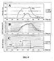
- a sampling probe for a mass spectrometer was located about 50 cm downstream of the catalyst outlet. Air, nitrogen and water flow was adjusted to form a mixer flowing at 800 SLPM (standard liters per minute) with a composition of 5% H 2 O, 8% O 2 , 0.3% He and the balance N 2 . This mixture was then heated to 370°C using the electric heater. Results of the tests conducted are provided in FIG. 8.
- FIG. 8A shows the mass spectrometer signal for H 2 and CO 2 converted to concentration units of percent by volume.
- FIG. 8B shows the temperature of the gas at the outlet of the catalyst as measured by three thermocouples placed just downstream of the catalyst at different locations across the outlet face.
- FIG. 8C shows the concentration of O 2 in percent and the fuel flow in g/min as set by the control system. At time equal to 298 seconds, fuel was turned on at 10 gm/minute flow rate. This fuel was combusted on the catalyst and the catalyst temperature rose rapidly as shown by the temperature of the three thermocouples-in FIG. 8B. That combustion is occurring was confirmed by the immediate appearance of CO 2 as measured by the mass spectrometer as shown in FIG. 8B.
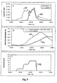
- FIG. 9 shows another example of hydrogen pulse generation.
- the catalyst used in this example was prepared in a manner similar to that of Example 1 with the exception that the metal foil was corrugated to have a channel height of 1.2mm. Air, nitrogen and water flow was adjusted to form a mixture flowing at 200 SLPM (standard liters per minute) with a composition of 8% H 2 O, 5% O 2 , 0.3% He and the balance N 2 . This mixture was then heated to 300°C using the electric heater.
- Graph A shows the mass spectrometer signal for H 2 and CO 2 converted to concentration units of percent by volume.
- Graph B shows the temperature of the gas at the outlet of the catalyst 906 and inside the catalyst at one inch from the outlet 904 as measured by two thermocouples.
- Graph C shows the fuel flow in g/min as set by the control system.
- fuel was turned on at 1.8 gm/minute flow rate. This fuel was combusted on the catalyst and the thermocouple near the catalyst inlet rose rapidly.
- the fuel flow is increased to 6.5g/min to provide a faster rate of temperature rise as shown by the temperature of the thermocouples in graph B. That combustion is occurring was confirmed by the immediate appearance of CO 2 as measured by the mass spectrometer as shown by 900 in graph A.
- the fuel flow is increased further to 10g/min generate a fuel rich exhaust as shown by 908 in graph C.
- H 2 appears as measured by the mass spectrometer and indicated by 902 in graph A.
- the fuel flow was terminated. The CO 2 and H 2 level rapidly decreased.
- Example 4 The catalyst of Example 1 was used to demonstrate a possible desufation cycle. Air, nitrogen and water flow was adjusted to form a mixer flowing at 500 SLPM (standard liters per minute) with a composition of 8% H 2 O, 8% CO 2 ; 7% O 2 , 0.3% He and the balance N 2 . This mixture was then heated to 250°C using the electric heater. As shown in Figure 10, at approximately 325 seconds fuel was turned on to raise the fuel processor temperature and produce an outlet gas temperature of 500 to 600°C. This high gas temperature will heat the downstream NSR trap catalyst to 500 or 600°C after a short time period.
- SLPM standard liters per minute
- the exhaust O 2 level is decreased and the fuel flow to the fuel processor is increased, 375 seconds in FIG. 10, to obtain an equivalence ratio greater then 1 and to produce H 2 and CO to desulfate the NSR catalyst.
- This reducing condition can be maintained for a long period or the reducing pulses containing H 2 and CO can be pulsed as shown in this example. Between pulses, a lower level of fuel is fed to the fuel processor to maintain the fuel processor temperature and the NSR catalyst temperature.
- the fuel to the fuel processing catalyst is turned off and the outlet gas temperature from the fuel processor drops rapidly.
- Example 5 This example demonstrates the effect of a thermal mass in series downstream of the fuel processor.
- the same catalyst as in Example 3 was used.
- the monolithic thermal resistance was assembled from 0.100 inch thick metal foil 100mm wide and corrugated to form a monolithic structure with a channel height of about 1.5 mm and weighing abut 550g.
- This thermal resistance was placed just downstream of the fuel processor catalyst of Example 3 and a thermocouple monitored gas temperatures upstream of the fuel processor catalyst, between the fuel processor catalyst and the thermal mass and downstream of the thermal mass. Air, nitrogen and water flow were adjusted to form a mixture flowing at 600 SLPM (standard liters per minute) with a composition of 8% H 2 O, 8% CO 2 ; 7% O 2 , 0.3% He and the balance N 2 .
- Curve 1100 represents the temperature measured downstream of the reformer and the curve 1102 represents the temperature of the exhaust downstream of the thermal resistance.
- the fuel was introduced.
- the gas temperature out of the reformer starts rising at 749 seconds and reaches a maximum of 576 C at 560 seconds (fuel flow was stopped at 758 seconds).
- the temperature of the thermal resistance rose much more slowly, reaching 445°C at 781 seconds due to its larger thermal capacity.
Abstract
Description
- This application claims priority to
U.S. Patent Application Serial No. 60/337,023 filed on December 3, 2001 - This invention relates generally to internal combustion ("IC") engines, and more particularly, to devices, systems, and methods for improving the performance and emission control of IC engines that produce nitrogen oxides ("NOx") emissions. It further relates generally to emission control systems, catalytic reaction systems, and fuel processing.
- Efforts to improve air quality have lead to strict government issued emission controls and regulations. Over the past 30 years, the allowable emissions from spark ignited gasoline engines have been substantially reduced. In tension with the efforts to reduce emissions is a general desire for increased fuel efficiency. This is particularly a problem with diesel engines, which while being very efficient often produce very high emissions of both NOx and particulate matter ("PM"). Indeed, in order to be compliant with gasoline spark ignited engine regulations, the emissions from a modern diesel engine must be reduced by a factor of around 10 to 50, depending on specific engine type.
- Lean-burn engines include both spark-ignition ("SI") and compression-ignition ("CI") engines. In comparison to conventional SI engines, lean-burn SI engines offer 20-25% greater fuel economy, while CI engines offer 50-100% greater fuel economy. CI engines are widely used throughout the United States in heavy-duty vehicles and their use in light-duty vehicles is expected to grow. CI engines are also widely used throughout much of the world in passenger vehicles, light and heavy-duty trucks, and electric power generators.
- Currently, automotive emission control is based largely on three-way catalyst technology, which reduces the emissions of carbon monoxide ("CO"), unburned hydrocarbons ('"UHCs") and NOx. This technology can be highly effective for ordinary gasoline engines operating at stoichiometric, or near stoichiometric air/fuel ratios. However, three-way catalyst technology is generally not suitable to lean burn engines, which generate a very lean overall exhaust mixture containing a large excess of oxygen. This is because the excess oxygen in the exhaust impedes the reduction of NOx, a major limitation of both lean-burn engines and TWC-based emission control technology. For example, in the case of lean-burn diesel engines, the emission control system must remove NOx and PM from an exhaust stream containing about 6-15% excess oxygen.
- Many technologies have therefore been explored to address the problem of NOx removal from lean-burn engine exhaust. One such technology utilizes NOx storage-reduction ("NSR" or NSR-type) systems. This technology has been described throughout the scientific literature and is generally well known in the art. For example, description of this technology may be found in S. Matsumoto, CATTECH, Vol. 4, No. 2, pp. 102-109, 2000, and the references cited therein, all of which are hereby incorporated by reference in their entirety.
- As described therein, a typical NSR catalyst has an adsorbent-catalyst system, providing the dual functions of reversible NOx storage or trapping, and NOx reduction. One component of the NSR catalyst reacts with NOx in the gas stream to capture it under oxidizing conditions or conditions where the exhaust stream contains excess O2. This component is selected so that when the exhaust stream is made reducing, that is, containing excess reducing species, the NOx is released. The NSR catalyst also contains a NOx reduction catalyst that reacts NOx with a reducing agent under reducing conditions to form non-polluting N2. When the exhaust stream is made reducing, the NOx is released and this NOx reacts with the reducing species on the NOx reduction catalyst to form N2. One example of an adsorbent-catalyst system is the Pt/Rh/Ba/TiO2/ZrO2/γ-Al2O3 system, which has been used commercially in vehicles in Japan.
- Main advantages of the NSR catalyst are its compatibility and effectiveness with fuel-efficient lean-burn IC engines; its commercial acceptance; its unneeded use of ammonia or urea as reducing agents; and its ability to obtain high NOx conversions when operated at ideal conditions. For example, NOx conversions of 90 to 100% have been achieved in tests of diesel engines under ideal conditions using diesel fuel as a reducing agent.
- However, NSR technology has some serious disadvantages and limitations as well. During regeneration of the NSR catalyst, the environment of the NSR catalyst must be made rich to convert the trapped NOx to N2 and to regenerate the catalyst. If the reducing environment in the exhaust were to be obtained by modifying the engine operation from lean to rich, then the engine cycle would be operating in a region where it was not designed to operate. For example a diesel engine, which usually operates without a throttle on the air intake, would now require a throttle to drive the air/fuel ratio into the rich regime. In addition, this would have to be done quickly and quite frequently, from about every 2 to 20 minutes.
- Fuel may be injected into the exhaust stream and combusted on the NSR catalyst or on an upstream oxidation catalyst in order to both consume the oxygen and to produce the reducing environment. At high exhaust temperatures, this has been shown to give reasonable regeneration cycles and NOx conversion efficiency. At low load and low exhaust temperatures, however, this procedure does not work well since the catalyst is not sufficiently reactive with diesel fuel. In addition, the high temperatures produced could drive the NSR catalyst to an undesirably high temperature.
- Another disadvantage of NSR technology is that NSR adsorbents are typically very sensitive to sulfur. The NOx adsorbent material can react with sulfur oxides contained in the fuel to form sulfates, as described for example in S. Matsumoto, CATTECH, Vol. 4, No. 2, pp. 102-109,2000; K. Yamazaki et al., Applied Catalysis B: Environmental, Vol. 30, Nos. 3 and 4, pp. 459-468, 2001 and the references cited therein, all of which are hereby incorporated by reference in their entirety. These sulfates are not readily decomposed and slowly convert the NOx adsorbent to an inactive sulfate, reducing its trapping efficiency. Even with low sulfur fuel (e.g., in the range of 15ppm) the NSR catalyst only lasts for about 500 to 1000 vehicle miles before its NOx trapping efficiency becomes significantly reduced. To produce a NSR catalyst that would last the 150,000 to 400,000 miles required by current and foreseeable emissions regulations, the NSR unit would have to be designed much too large to be conveniently utilized within the industry. While it has been found that the NSR catalyst unit can be desulfated by treatment in a reducing atmosphere at temperatures of 500-650°C, it is very difficult to operate an engine in a manner so as to produce this environment within the NSR trap unit itself.
- Use of diesel fuel as a reductant by direct injection into the exhaust is not very effective at exhaust stream temperatures from 150-250°C, which covers a significant portion of the operating cycle of a diesel engine, including idle and low load. While high NOx conversions may be possible using a diesel reductant at high inlet temperatures (e.g., ranging from 250-300°C or above), these temperatures are often unobtainable over a sufficiently wide spectrum of operating conditions to make this a useful approach. Other reducing agents, such as hydrogen, carbon monoxide, alcohols and some low molecular weight hydrocarbons (e.g., propylene), are more reactive at low temperatures and may provide better reducing capacities within a wider range of operating conditions. However, use of these materials would require the vehicle have an additional fuel source, posing significant infrastructure and design implications as well as increased costs. These disadvantages and limitations have largely prevented widespread commercial use and acceptance of NSR technology.
-
Published PCT patent application WO 01/34959 A1 by H. S. Hwang et. al. - This approach has several disadvantages however. First, the processor is limited to producing the reducing agents, it does not aid in reducing the oxygen level in the exhaust. In addition, this device cannot provide a high enough exhaust temperature to facilitate either optimum NSR catalyst regeneration, or desulfation. Further, if the device is to be used only intermittently, the fuel and air must be operated intermittently. This may be very difficult since the fuel processor must be maintained at elevated temperatures to function properly. During idle or low load operation, the NSR catalyst may be regenerated only once every 10 to 20 minutes for optimum fuel economy. In addition, since the fuel processor must be maintained at elevated temperatures for very long periods, even when not needed, energy expenditure is significantly increased and fuel economy is adversely affected. Lastly, because partially processed fuel, H2 and CO may be generated continuously, they must be stored until needed for the regeneration cycle. This complicates the overall system design. Thus, a great need remains for methods and devices that can overcome the disadvantages and limitations of the currently available NSR systems, and at the same time provide a practical solution to the current emissions and fuel efficiency problems.
- The present invention fills this need by providing systems and processes that enable NSR technology. In this way, large-scale commercial use of diesel and other lean-burn engines with NSR technologies is facilitated. This in turn helps to conserve petroleum and to reduce greenhouse gas emissions while ensuring compliance with strict environmental regulations.
- Accordingly, it is an object of the present invention to provide improvements in the performance and emissions of lean-burn IC engines equipped with NSR or NSR-type emission control systems. It is a further object to provide a device capable converting a fuel, such as diesel or gasoline, into a reducing gas mixture containing CO and H2 at a temperature compatible for use with NSR systems. It is yet another object to provide a reducing gas mixture capable of regenerating a NOx adsorbent, reducing NOx to nitrogen, and periodically desulfating a NSR-type emission control system catalyst. It is still a further object to provide a NOx reducing agent and adsorbent-catalyst desulfating agent that is more efficient than diesel fuel. It is still a further object to enable IC engines to be operated in continuous lean-burn mode, rather than intermittent lean/rich-burn mode. These and other objects and advantages will become apparent from the description set forth hereinafter and the drawings attached hereto.
- In one aspect, the present invention fulfills these objects by providing a system for reducing NOx in an exhaust stream containing excess oxygen comprising, a NSR catalyst, a fuel processor, and at least one fuel injector port. The fuel processor is located at a position upstream of the NSR catalyst and comprises an inlet, an outlet, and at least one catalyst. Fuel is injected into the fuel injection port and reacts on the fuel processor catalyst to rapidly increase the temperature of at least a portion of the fuel processor catalyst and at least a portion of it is converted to H2 and CO.
- In some variations the system further comprises a thermal mass having a heat capacity greater than that of the fuel processor. The thermal mass may for example be a PM filter, a monolithic structure, or may be a portion of the NSR catalyst or fuel processor. The system may optionally comprise a fuel preheater, a fuel vaporizer, a mixer, and a control system.
- In another aspect, the present invention fulfills these objects by providing a method for regenerating an NSR catalyst adsorbent comprising the steps of providing an exhaust stream from an engine, injecting fuel into a position upstream of a fuel processor, optionally mixing the exhaust stream with the fuel, reacting the fuel and exhaust stream mixture within the fuel processor to generate a reducing gas mixture comprising CO and H2, and introducing the reducing gas mixture into a NOx trap, whereby the adsorbent is regenerated by introduction of the reducing gas mixture.
- In one variation the fuel is vaporized prior to injection. In another variation, the fuel is injected at an equivalence ratio greater than 1. In another variation, the fuel may be either gasoline or diesel fuel. In yet another variation, at least a portion of the catalyst is heated to at least 500°C.
- In another aspect, the present invention fulfills these objects by providing a fuel processor unit for use with a NSR system comprising an inlet, an outlet, at least one catalyst, and at least one fuel injection port. The fuel injection port is located at a position upstream of the catalyst and facilitates the injection of fuel into the catalyst. At least a portion of the fuel reacts on the catalyst to rapidly raise the temperature oaf at least a portion of the catalyst, and at least a portion of the fuel is converted to H2 and CO. In some variations, the fuel processor unit further comprises a mixer or additional catalysts.
- In still another aspect, the present invention provides control strategies for use with the systems and methods of the present invention.
- The foregoing and other aspects of the present invention will best be appreciated with reference to the detailed description in conjunction with the accompanying drawings, wherein:
- FIG. 1 depicts NOx adsorption and reduction in an illustrative NSR system.
- FIG. 2 illustrates one variation of the system of the present invention wherein a fuel processor is located upstream of a NSR system.
- FIG. 3 illustrates one variation of the fuel processor of the present invention, wherein the fuel processor comprises a single catalyst.
- FIG. 4 provides a time-based graph illustrating one method of operating the fuel processor in accordance with the present invention.
- FIG. 5 illustrates one variation of the present invention wherein the fuel processor comprises two catalysts in series.
- FIG. 6 illustrates one variation of the present invention wherein the fuel processor comprises two catalysts in parallel.
- FIG. 7 provides an illustrative set of thermal response curves for fuel processors having different thermal masses.
- FIG. 8 provides test results indicating rapid heat up and generation of H2 using the present invention.
- FIG. 9 provides test results indicating rapid heat up and generation of H2 using the present invention with an alternative fuel and engine schedule.
- FIG. 10 provides test results using one possible desulfation scheme using the fuel processor of the present invention.
- FIG. 11 provides test results indicating rapid heat up and generation of H2 and CO using the present invention with a system containing a thermal mass downstream of the fuel processor.
- In one aspect, the present invention provides a system for improving the performance and emission control of IC engines, and in particular, lean-burn engines equipped with a NSR catalyst. When reference is made herein to a "NSR catalyst," it should be understood that all systems having a NOx adsorbent-catalyst system are embodied thereunder. Making reference now to the drawings, wherein like numerals indicate like elements throughout the views, there is illustrated in FIG.1, the operation of a typical NSR catalyst.
- As shown therein, as exhaust gas flows through the catalyst during
adsorption cycle 100, NOx is adsorbed in the presence of excess oxygen by an adsorbent. The NSR catalyst may be designed so that the adsorption is very efficient, with nearly complete adsorption of NOx from the exhaust stream, as shown bycurve 102. The NSR catalyst typically comprises a canister situated in the exhaust unit to enable the exhaust gas to flow therethrough. Typical catalysts are honeycomb like, monolithic structures having the adsorbent and catalyst components coated onto their surfaces or walls. - As the adsorbent in the NSR catalyst becomes saturated with NOx, the adsorption becomes less complete and the NOx level exiting the NOx trap begins to increase as shown by
curve 104. At this point, the composition of the exhaust stream is changed from an oxidizing to a reducing state, andreduction cycle 106 begins. A reducing agent is then introduced and the oxygen level is reduced to zero as shown bycurve 108. - In a reducing environment, the NOx is desorbed from the adsorbent and is reduced to nitrogen by the catalytic components of the NOx trap. This reaction generally occurs with sufficient speed so that
reduction cycle 106 is relatively short while at the same time permits sufficient time to elapse so that a significant fraction of the NOx adsorption capacity is regenerated. The exhaust composition then reverts back to its normal oxidizing condition, and the entire cycle is repeated. Typically,adsorption cycle 100 lasts anywhere from 1 to 5 minutes at high load and possibly 20 minutes at low load or idle. Regeneration-reduction cycle 106 typically lasts 1 to 10 seconds and possibly longer depending on the time required to regenerate the NSR catalyst. - The reducing gas composition for regeneration-reduction is obtained by injection of extra fuel into either the engine cylinders late in combustion (i.e., during the end of the power stroke or during the exhaust stroke), or directly into the exhaust pipe upstream of the NSR system. The overall NOx conversion or removal performance of this technology is affected by the regeneration-reduction performance of the adsorbent-catalyst system. Thus, if the regeneration cycle is ineffective, the subsequent adsorption cycle is inefficient and the NOx levels exiting the exhaust are typically very high.
- Turning now to FIG. 2, there is shown a general schematic of the system of the present invention. As illustrated therein,
fuel processor 200 may be located at a position alongexhaust pipe 202 at a distance betweenengine 204 andNSR system 206. In this way, the exhaust stream will flow first throughfuel processor 200 and then throughNSR system 206.Fuel processor 200 may be located together withNSR system 206 in a single housing structure, or it may not be. In one variation, as will be described in more detail below,fuel processor 200 is operated intermittently to periodically regenerate the NSR adsorbent of theNSR system 206. When regenerating the NSR adsorbent,fuel 208 may be injected intofuel processor 200, injected at a position upstream offuel processor 200, or may be injected directly into bothfuel processor unit 200 and at a position upstream thereof. - In one variation,
fuel processor 200 comprises at least one catalyst, as shown in FIG. 3. As illustratively shown therein,fuel processor 200 comprisesinlet 300,outlet 302, and at least onecatalyst 308. At least onefuel injection port 304 and anoptional mixer 306 are located at a position upstream of the fuel processor. In addition,fuel processor 200 may further comprise a fuel preheater, fuel vaporizer, a secondary injection port for the introduction of air or additional fuel (not shown), and a control system (not shown). - As illustratively shown in FIG. 3,
fuel processor 200 comprisesinlet 300 for receivingexhaust gas mixture 310.Fuel injection port 304 is located at a position upstream offuel processor 200 for receiving fuel therein. After the fuel is injected intoport 304, it entersfuel processor 200 and combines withexhaust gas mixture 310. The fuel to be injected intoport 304 may take the form of a vapor, a liquid, or a combination of the two. If the injected fuel is a liquid, then some or all of it may be vaporized when contacted by the hot exhaust gas mixture. Mixing may further accelerate this vaporization. Thus,exhaust gas mixture 310 and the injected fuel may pass through anoptional mixer 306.Mixer 306 may be any suitable mixer that promotes mixing of gases and aids the vaporization of liquid droplets. - The mixture may be sufficiently uniform so that the resulting equivalence ratio (Φ) is within any desired limit, where the equivalence ratio is the fuel concentration divided by the theoretical fuel concentration needed to fully react all the oxygen present in the gas mixture to form CO2 and H2O. For example, if the fuel processor is to be used to reduce the oxygen concentration in the exhaust to zero before it enters the NOx trap, then the level of mixing will determine the required mixture equivalence ratio. If the mixer produces a mixture at the catalyst inlet of +/-10% uniformity then fuel may be added to give an equivalence ratio of 1.1 so that the lowest equivalence ratio at the catalyst is 1.0. Similarly, for the portion of the fuel processor operating rich to produce H2 and CO, the mixture uniformity will likely be determined by the required equivalence ratio and the required temperature to obtain the necessary reforming performance. In general, mixture uniformity from +/- 20% is desirable, while +/- 10% is more desirable, and +/- 6% is most desirable.
- In one variation, a static (i.e., having no moving parts), in-line mixer that mixes the components into a relatively homogeneous stream is used. In this variation, the mixer acts by changing the flow of the gas stream components, thereby causing mixing of the inlet stream. Various types of static mixers are commercially available and may be used. For example, one type of static mixer has an array of intersecting channels that split the stream into portions, which portions are then rearranged and combined. Other types of mixers include swirlers and counter rotating swirlers, which impart a swirl to the gas mixture. The swirler may have a portion rotating in one direction and another portion rotating in the opposite direction. Pipe sections may also be used as mixers. For example, straight pipe sections with a length/inner diameter ratio (L/Di) greater than 5 or bent pipe sections may be used.
- Alternatively, the mixer may have moving parts such as fans, turbines, or acoustic energy input devices, which induce turbulence or mixing within the gas streams. Such mixers may be less desirable, however, since the moving parts may wear and require service and may also require a greater energy input. Evaluation of any improvement in mixing efficiency should be made before determining whether a non-static mixture is sufficiently advantageous to tolerate the additional design complexity and energy consumption.
- In addition, it is possible for varnish or carbonaceous deposits to form on the parts of the mixer in contact with fuel spray, especially if the fuel has a high molecular weight and is prone to pyrolysis. Varnish is a hydrocarbon like coating formed by partial pyrolysis of the diesel fuel. Parts of the mixer may be coated with a catalyst capable of oxidizing these varnish or carbonaceous deposits. In this way, the catalyst prevents or removes the deposits, much like a continuous-cleaning or self-cleaning oven.
- In one variation, fuel injection ports may be used as mixers. In one variation, the fuel injection ports are located upstream of the fuel processor in the exhaust pipe and a length of the exhaust pipe is used to mix the gas mixture uniformly. The section of pipe length necessary to perform this function is generally thought to be ten times the pipe diameter length. The injection ports may also be located upstream of a bend in the exhaust pipe to further mix the fuel and air. In some instances, it may be desirable to mix the fuel and air quickly or in a short distance prior to their introduction into the catalyst. This is because heavy fuels (e.g., diesel fuels) are prone to pyrolysis or decomposition and produce varnish or other deposits, which may in turn lead to the degradation of the system. In another variation the fuel injection ports of the engine are used as mixers.
- The fuel and exhaust mixture then flow into
catalyst 308 for reaction. A portion of the fuel reacts with oxygen, while the remaining fuel reacts with water to form carbon monoxide (CO) and hydrogen (H2) by processes well known in the art. The H2 and CO then flow out ofcatalyst 308 and out of the fuel processor viaoutlet 302. The H2 and CO may then flow downstream toNSR system 206, as shown in FIG. 2. Since the gas mixture comprises a H2 and CO reducing gas mixture, containing little or no oxygen, the NSR unit will be rapidly and efficiently regenerated. At the completion of this regeneration cycle, the fuel flow to the fuel processor is terminated and the system returns to adsorption mode. -
Catalyst 308 may comprise a single catalyst unit or may comprise several catalysts in series. For example, a first catalyst may be designed primarily as a combustion catalyst with a catalyst composition selected to react with some of the fuel and oxygen to form carbon dioxide and water and generate heat. Excess fuel and/or fuel injected between catalyst units could then pass to a second catalyst unit where the excess fuel can react with water and carbon dioxide to form CO and H2. This second catalyst can be designed primarily as a reforming catalyst for example. Alternatively, a single catalyst can be designed having an inlet section for oxidation and an outlet section for reforming. In this way, a single catalyst is provided that effectively functions as two separate catalyst units. -
Catalyst 308 may comprise one or more metals or oxides as the active catalyst combined with a high surface area refractory support, many of which are well known in the art for oxidation of hydrocarbons. The catalyst may be applied as a washcoat, a porous coating typically comprising a mixture of a high surface area support and active catalyst elements. Alternatively, the coating may comprise a support with a porous structure that has a second oxide portion or a mixture of oxides active for the oxidation of hydrocarbons or carbon. The coating may be applied using any number of processes. For example, it may be applied using plasma flame spraying, chemical vapor deposition, electroplating, electroless plating, application of a sprayable sol (comprising a suspension of the catalyst particles in a liquid), or be applied by dipping the parts into a slurry. One example of a catalyst composition that may be used with the present invention is described inU.S. Patent No. 5,232,357 by Dalla Betta et. al. , which is hereby incorporated by reference in its entirety. - The fuel used in the fuel processor may be any fuel compatible with the unit. For example, it may be the same type of fuel as used in the engine. When the fuel is a liquid, such as diesel fuel or gasoline, the exhaust gas mixture may not be hot enough to vaporize the fuel completely. In these circumstances, the mixture temperature may be increased sufficiently to cause some portion of the fuel to react with the oxygen in the exhaust stream passing through the catalyst, thereby causing the catalyst temperature to increase. As
fuel processor catalyst 308 increases in temperature, the remaining liquid fuel may be vaporized within the catalyst. - Alternatively, the fuel may be preheated so that it is more readily vaporized upon injection. An optional fuel heater may be positioned at any convenient location, either within the fuel processor unit itself, or any desirable position upstream thereof. The fuel may be injected either continuously or intermittently, for the duration of the regeneration cycle. In the case of continuous fuel injection, the rate and duration of the fuel flow controls the fuel quantity. In the case of intermittent fuel injection, the pulse frequency and pulse volume controls the fuel quantity. The quantity of fuel injected is typically sufficient to react with all of the excess oxygen present in the exhaust stream and to generate the required amount of reducing gas mixture (CO and H2) at the operating temperature of the NSR system. This quantity of fuel corresponds to an equivalence ratio (Φ) greater than 1.
- Fuel is generally not injected during the NOx adsorption phase, which typically lasts 1 to 5 minutes at high loads and longer at low load or idle. Then fuel is injected again for about 1 to 10 seconds during the NOx regeneration-reduction phase, and the cycle is repeated as long as the engine is operating and is producing NOx. The quantity and timing of fuel injection may be optionally controlled by a fuel processor control system, which may be linked to or be part of, the engine management system or engine control unit.
- The H2 and CO reducing agent can be formed by a variety of reactions. In one variation, a portion of the fuel is combusted to raise the catalyst temperature to approximately 500 to 700°C and the remaining fuel reacts with H2O and CO2 in the exhaust stream or formed by the fuel combustion to produce the desired H2 and CO. Alternatively, the fuel, O2, H2O, and CO2 can react simultaneously on the catalyst to yield the desired H2 and CO.
- The fuel processor can be operated in any of several modes. One mode of operation is shown for example, in FIG 4. As shown therein, the
regeneration cycle 400 consists of a heat up phase A and a reduction phase B. The oxygen concentration-402 from the engine, fuel flow to thefuel processor 404, CO and H2 produced by thefuel processor 406 and temperature of thefuel processor catalyst 408 are indicated. At the start of heat up phase A, fuel is injected to the fuel processor at a rate indicated by 410. This heats the fuel processor catalyst to the desired temperature as shown incurve 408. - When the temperature of the fuel processor catalyst has reached the desired level, the fuel flow is increased 412 and the
oxygen level 402 is decreased by partially throttling the airflow to the engine. The combination of decreasing the oxygen concentration and increasing the fuel concentration causes the overall mixture at the fuel processor catalyst to become rich, that is, having an equivalence ratio of greater than 1, and CO and H2 is produced as shown incurve 406. When the NOx trap within the NSR system is fully regenerated, fuel input to the processor is terminated and the engine throttle reopened. One advantage of this cycle is that fuel consumption is minimized. In addition, since the engine is throttled only during the period in which CO and H2 is generated, any negative effects on engine performance and drivability are minimized. - Alternative operating procedures are also possible. For example the fuel flow into the fuel processor can be immediately raised to that level required for reducing agent generation. Then when the fuel processor has achieved an adequate temperature, the engine may be throttled to produce an overall reducing mixture of CO and H2. This can facilitate faster fuel heat up of the fuel processor catalyst since the amount of fuel combustion is higher. However, particular care should be taken in order to avoid overheating the catalyst, thereby deactivating it.
- During the regeneration cycle, the outlet gas stream from the fuel processor is free of oxygen, including oxygen that might bypass
catalyst 308. This is because this oxygen will mix with the reducing gas mixture and react on the NSR catalyst thus reducing the effectiveness of the regeneration process. In addition, the engine operating procedure can take a number of forms. Rather than throttling the engine to reduce the exhaust oxygen concentration, the exhaust gas recirculation system ("EGR") flow can be increased, thus causing the exhaust oxygen level to decrease. Alternatively, the amount of fuel injected into the engine by the engine fuel injectors can be increased. In addition, a combination of these methods or other methods can be used to decrease the exhaust oxygen level. - In one variation, the fuel processor comprises catalysts in series. In this variation, an oxidation catalyst is positioned upstream of a reforming catalyst as shown in FIG 5. As shown therein,
fuel processor unit 200 comprisesoxidation catalyst 500 upstream of reformingcatalyst 502. The exhaust gas flow enters the fuel reformer throughinlet 504 and passes throughmixer 506,oxidation catalyst 500,second mixer 508, reformingcatalyst 502 and then throughoutlet 510. - In this variation, fuel may be injected via
fuel injector 512 and be reacted onoxidation catalyst 500 to heat up the reformingcatalyst 502. At any desirable time, fuel may also be injected viafuel injector 514 to further increase the fuel/air ratio to reformingcatalyst 502 so that reforming can occur to produce CO and H2. One advantage of this variation is that the functions of the oxidation and reforming catalysts are separated. In this way each catalyst may perform their function very efficiently. - For example, during operation, oxidation catalyst could be configured to operate under constant conditions of excess oxygen (equivalence ratio less then 1.0), thereby facilitating high activity and low deposition of carbon or hydrocarbons. Additionally, since reforming
catalyst 502 may be separately fueled via one or more injectors at a position nearfuel injector 514, the fuel can be added once the temperature of the reforming catalyst has reached its optimal level. In addition, having a separate oxidation catalyst enables its placement close to the engine, thereby facilitating its operation at higher exhaust gas temperatures. This in turn helps provide better operation at idle and at low ambient conditions. - The two catalysts in series in this variation may have any number of configurations. For example, the catalysts may be located at a distance separate from one another and have separate upstream injectors and mixers. Alternatively, the two catalysts may be located within a single unit. Having the catalysts located within a single unit has the advantage of making each system easily replicable, thus providing a manufacturing advantage.
- In another variation, the catalysts are in parallel, as shown by FIG. 6. The exhaust gas enters through
port 600. Fuel may be injected viafuel injectors 602 where it is then mixed with the exhaust gas bymixer 604. The fuel and exhaust mixture then passes throughcatalyst 606 andoutlet 608. A portion of the exhaust mixture passes throughpassage 612 and then throughcatalyst 614 and on tocommon outlet 608.Catalyst 606 is an oxidation catalyst andcatalyst 614 is a reforming catalyst or combination combustion and reforming catalyst that hasseparate fuel injector 610. - In this variation, fuel is first added to
fuel injector 610, which heats up reformingcatalyst 614 to the desired temperature. When the temperature ofcatalyst 614 is within the desired range and a reducing mixture is required, fuel is injected viainjectors 602 at an equivalence ratio close to 1.0. This consumes the oxygen in the main exhaust flow. Optionally, additional fuel may be added viainjector 610 to make the equivalence ratio of the mixture atcatalyst 614 above 1.0 and to produce CO and H2. It should be noted that the equivalence ratio of the mixture atcatalyst 614 will increase when fuel is injected throughinjectors 602. This is because the fuel is mixed with the portion of the exhaust flow that is flowing tocatalyst 614, making the fuel composition atcatalyst 614 the sum of the equivalence ratio frominjectors - The overall system design may be modified in any number of ways. For example, the system may be modified so that fuel from
injectors 602 is not mixed with the exhaust flow that goes tocatalyst 614. Alternatively, the catalysts may be located at positions separate from one another. For example, they may be located in separate units and have separate fuel injectors and mixers. - One advantage of the parallel configuration illustrated by FIG. 6 is that the reforming catalyst can be preheated to a high temperature by applying fuel only to the section nearby. If the size of
catalyst 614 is small relative tocatalyst 606 and the fraction of exhaust flow through 614 is small compared to 606, then the amount of fuel used to heat reformingcatalyst 614 to the desired reforming temperature would be minimized. Also,catalyst 614 can be designed with a very small thermal mass so that heat up occurs quickly, further minimizing fuel expenditure. - On the other hand, it may be desirable that the downstream NSR system catalyst not be heated too high in temperature since this may damage it or drive it out of its desired operating range for adsorption. This may be accomplished by increasing the thermal mass of
catalyst 606 so that when fuel is added toinjectors 602 to remove the oxygen from the main exhaust flow, the catalyst and the exit gas flow from 606 rises slowly. Alternatively, a thermal mass may be placed downstream of the fuel processor unit to absorb the heat from the fuel processor outlet stream and reduce the gas stream temperature prior to entering the NSR system. - The catalysts of the present invention may be composed of any suitable material. For example, they may be composed of pellets or beads in a container, or may be monolithic honeycomb type units. A monolithic honeycomb unit may be desirable because vehicle vibration may cause abrasion and loss of pellet or bead material. Additionally, the monolithic units typically have a lower pressure drop for the flowing exhaust stream. Any monolith may be used. For example, the monolith may be ceramic or may be metal and may have a variety of cell sizes and shapes. Determination of the cell size and shape is dependent on the desired surface area and pressure drop, as well as the relevant heat and mass transfer coefficients. For example, it may be desirable that the fuel processor catalyst have a low heat capacity so it can heat up quickly. Similarly, it may be desirable that the fuel processor catalyst have a low pressure drop so that the overall pressure drop of the entire system does not present a hindrance to operation or reduce the efficiency of the engine.
- When a monolithic structure is used for the catalyst substrate, its external or wall surfaces may be coated with a layer of catalyst. This washcoat may comprise a porous inert oxide such as alumina or zirconia and have a highly exposed surface area. This oxide support may contain additional components active for oxidation or reforming depending on the desired function. Preparation and composition of various monolithic catalysts for use with the present invention are described in
U.S. Patent Nos. 5,183,401 ,5,259,754 , and5,512,250 to Dalla Betta et. al. , each of which are hereby incorporated by reference in their entirety. - The oxidation catalyst may comprise any catalyst capable of oxidizing hydrocarbons. For example, the oxidation catalyst may comprise elements selected from any of Groups VI, VH, VIII and IB of the periodic table of the elements. The more active catalytic elements may be selected from the group Pd, Pt, Ir, Rh, Cu, Co, Fe, Ni, Ir, Cr, and Mo. In some instances, it may be more desirable to use Pd, Pt, Rh, Co, Fe, or Ni, which may be used separately or in combination and may further exist as the element or the oxide in actual use.
- One property of the oxidation catalyst that may be desirable is that it has good catalytic activity at very low temperatures. In this way, oxidation can be initiated at low exhaust temperatures without modification of the system design. This property is often referred to as light off temperature, or the temperature at which the fuel and oxygen in the exhaust begins to react. This typically requires that the temperature be below 250°C and more typically below 150°C.
- The oxidation catalyst may be deposited on supports comprising aluminum oxide, silicon oxide, zirconium oxide, or mixtures and combinations thereof, or mixtures or combinations thereof with additional components or elements. Examples are cerium zirconium oxide mixtures or solid solutions, silica alumina, Ca, Ba, Si, or La stabilized alumina, as well as other supports well known in the art. Since diesel fuel with a high molecular weight has a propensity to pyrolyze at high temperatures, the catalyst may also contain catalytic components active for steam cracking of the hydrocarbon fuel. Possible additives may include basic oxides such as calcium oxide, barium oxide, other alkali or alkaline earth oxides and rare earth oxides. The catalyst can be made by impregnating Pd, Pt or any other active catalyst within a porous support such as alumina or zirconia. The metal loading could be in the range of 0.1 to 20% by weight, and more desirably, in the range of 1 to 10% by weight. Several illustrative catalysts that may be used with the present invention include those described in
U.S. Patent No. 5,232,357 to Betta et. al. , which is hereby incorporated by reference in its entirety. - The reforming catalyst may similarly use a high surface area support with added active components. For example, the reforming catalyst may comprise components Ni, Rh, Pd, Pt. The catalyst may be selected so that it is capable of remaining stable under normal lean oxidizing conditions and then responding very quickly to the addition of fuel so that H2 and CO are thereby reformed. In this respect, it may be desirable to use Pt, Pd and Rh supported on a porous oxide support.
- For example, a typical reforming catalyst may comprise 1 % Rh by weight supported on a porous zirconium oxide substrate. This may be accomplished by dissolving rhodium trichloride in water and then impregnating the solution onto a solid zirconium oxide substrate having a high surface area (e.g., ranging from 15 to 150 m2/g). The rhodium concentration may typically be in the range of 0.1 to 20% by weight of the total washcoat catalyst solid. More typically, the rhodium concentration may be in the range of 1 to 10% of the total washcoat loading. The washcoat may be coated onto the interior channels of a monolithic honeycomb structure at a loading thickness of 1 to 50 mg/cm2 or more typically, in the range of 5 to 15 mg/cm2. Pd or Pt catalysts may be prepared in a similar manner.
- The oxidation and reforming catalysts may be combined in the same monolithic unit by combining in the washcoat both the oxidation and reforming components. For example, the active oxidation catalyst Pd and the active reforming catalyst Rh may be combined on a zirconia support to form a catalyst having the oxidizing activity to react the fuel with the oxygen and the reforming activity necessary to reform the remaining fuel to CO and H2. Alternatively, the Rh component may be coated onto the monolithic substrate and calcined or fixed. Separately the Pd may be coated onto a high surface area support and calcined or fixed. These catalysts may also be mixed together to form a Pd/Rh catalyst and this mixed catalyst then coated onto the monolithic substrate.
- In one variation, a thermal mass is used to help control the system operation, and in particular, to help moderate the temperature between the fuel processor and the NOx trap catalyst. This may be important because while the optimal operating temperature range for the fuel processor may be quite high, the optimal operating temperature range for the NSR system might not be. This may be because the NOx trap catalyst may be deactivated at high temperatures. Any number of thermal mass configurations are possible for use with the present invention and any number of thermal masses may be employed.
- In one variation, the thermal mass of the fuel processor catalyst itself is selectively controlled. For example, it may be desirable that the catalyst heats up as rapidly as possible to consume as little fuel as possible. This typically involves controlling the thermal mass of the fuel processor catalyst, so that it is as relatively small. In another variation, a thermal mass may be placed downstream of the fuel processor to absorb the heat it releases in order to help prevent the overheating of the NSR system. This thermal mass may be a PM filter or soot trap placed between the fuel processor and NSR system or may be a separate thermal mass component. When a soot or PM filter is placed between the fuel processor and the NSR system as the thermal mass, the NSR system may be maintained at a constant temperature. One advantage of this design is that the heat generated by the fuel processor may be used to heat up and regenerate the particulate trap by helping to burn off the carbonaceous soot.
- The thermal mass may be made of any suitable material. For example, it may be ceramic or may be metal. It can have a high heat capacity and a low pressure drop to ensure that the pressure drop across the entire system does not hinder system operation. The optimal range of thermal mass is a function of at least the gas flow rate and the desired temperature rise, and thus may be selectively controlled. In another variation, the NSR system itself may be designed with a high thermal mass.
- FIG. 7 provides results of a computer simulation of catalyst heat up during the combustion of a fuel and air mixture. The following assumptions were made: the energy release required was for complete combustion of diesel fuel; the energy of the combustion was used to heat the gas mixture flowing through the catalyst and to heat the catalyst itself; there was good heat transfer between the gas and the catalyst; and the gas flow rate was typical of a catalyst unit sized for a vehicle. As shown in FIG. 7, the catalyst unit heats up rapidly once the fuel is turned on. At a metal monolith wall thickness of 100 microns, the catalyst unit reaches 450°C in about 12 seconds. At a wall thickness of 50 microns it reaches 450°C in about 6 seconds and at a wall thickness of 25 microns, it reaches 450°C in about 3 seconds. Thus, for rapid heat up, a low wall thickness with a resulting low thermal mass is desirable. However, it should be noted that there may be other design considerations that may influence the selection of the wall thickness or thermal mass. These include the mechanical durability of the catalyst and the resistance to oxidation of the metal.
- Typical wall thickness for a metal monolithic reforming catalyst unit would be in the range of 10 to 200 microns, and more typically 25 to 50 microns. The oxidation catalyst unit in the parallel configuration of FIG. 6, or a thermal mass in a series configuration, could be substantially thicker, typically 50 to 500 microns and more typically 100 to 200 microns. In addition, as discussed above, while it may be desirable to have the reforming catalyst heat up rapidly to generate hydrogen quickly, it is often not desirable to have the oxidation catalyst heat up too rapidly since this may overheat the downstream NSR catalyst.
- In another aspect, the present invention facilitates desulfation of a NOx trap. Sulfur in engine fuel produces sulfur oxides, SO2 or SO3, in the exhaust system. These sulfur oxides ("SOx") can react with the components of the trap to form sulfates, which in turn can deactivate the NSR system. While typical levels of sulfur in fuel are relatively low, making the deactivation of the trap take anywhere from days to weeks (corresponding to 100's to 1000's of miles of engine usage), the trap must be able to work far longer than this. The system and methods of the present invention can thus be used to desulfate the trap. In one variation, this is accomplished by operating the oxidation portion of the fuel processor to produce an outlet gas stream having a temperature in the range of 500 to 800°C. This in turn heats the downstream NSR system to a temperature in the range of 500 to 700°C.
- When the NSR system is at the desired temperature, the fuel flow to the fuel processor and the engine throttle may be adjusted to produce H2 and CO and reduce the oxygen concentration exiting the fuel processor to zero. This reducing gas mixture will then regenerate the NOx trap by decomposing the sulfates and other species that have caused its deactivation. This hot reducing gas mixture can be maintained until the regeneration is complete. In one variation, the regeneration temperature range for the NSR system is typically from about 100 to 800°C and more typically, from about 500 to 700°C. In addition, the H2 and CO reducing agent can be fed to the NSR catalyst for regeneration as a continuous long reducing pulse or as many short pulses.
- In one variation, a control processor or control system may be used to control various aspects of the present invention. Any number of control strategies may be employed. For example, a control system may be used to map NOx output versus a given engine operating condition, such as load or speed. In this way, the NOx collected by the NSR trap may be estimated and as the trap reaches capacity, the NOx regeneration cycle may be initiated. Alternatively, a NOx sensor may be placed downstream of the NSR trap. In this way, once the sensor perceives that the NOx trap has reached capacity (e.g., by measuring breakthrough NOx levels), the regeneration cycle may be initiated.
- Similarly, a control system may be used to monitor and control any or all system temperatures. Illustrative temperatures that may be controlled include inlet and outlet gas mixture temperatures, fuel input temperature, and catalyst temperature. For example, the reformer catalyst temperature may be monitored and controlled via a thermocouple or other temperature-sensing device placed near the outlet of the catalyst.
- In a like manner, the temperature at the outlet of the fuel processor can be measured and monitored using a thermocouple. The temperature may be controlled by adjusting the fuel flow to the fuel processor while leaving the oxygen level in the exhaust constant. Alternatively, the temperature may be controlled by keeping the fuel flow to the fuel processor constant while adjusting the oxygen level, for example, by throttling the engine. Yet another alternative is to adjust both the fuel flow to the fuel processor and the O2 level. This would allow the system to control both the fuel processor outlet temperature, and the equivalence ratio. In this way, the level of H2 and CO may be effectively controlled.
- The fuel processor temperature may be monitored by measuring the gas temperature at the outlet or by measuring the actual temperature of the catalyst itself. To minimize fuel usage by the fuel processor unit, a combustibles sensor, or H2 or CO sensor may be placed downstream of the NSR trap unit to sensor the breakthrough of H2 and CO reducing agent. This in turn signals the control system to stop the regeneration cycle.
- If the fuel processor unit is used to desulfate the NSR trap unit, then it may be desirable to measure the temperature at the outlet of the fuel processor unit to limit the operating temperature to insure durability. In addition, the temperature at the outlet of the NSR trap unit may be measured to ensure that the NSR unit is at the desired temperature for regeneration. In addition, the temperature of the fuel processor unit may be modulated to obtain the desired temperature of the NSR unit for proper desulfation.
- A control system may also be used to control the equivalence ratio. For example, when H2 and CO are to be generated by the fuel processor reformer, the equivalence ratio at the inlet to the reformer catalyst can be controlled by changing the fuel flow or by throttling the airflow to the engine. More specifically, at normal operating engine airflow, fuel may be added to the reformer catalyst until the temperature is within the range required for reforming the fuel to H2 and CO. At this point, the engine airflow can be throttled to reduce the airflow and O2 concentration in the exhaust. This in turn will increase the equivalence ratio at the catalyst and drive it into the rich region to generate H2 and CO. It is also possible to adjust the fuel flow to the reformer to adjust the equivalence ratio or to adjust both the engine throttle and the fuel flow to obtain the desired reformer equivalence ratio.
- The equivalence ratio at the reformer and at the oxidation catalyst can be calculated from a number of engine parameters, including engine RPM and throttle setting (which in turn provides engine air flow), engine fuel flow, and fuel processor fuel flow(s). Alternatively, the exhaust O2 level can be measured using an O2 sensor in the exhaust upstream of the fuel processor and combined with the fuel processor fuel flow to calculate equivalence ratios.
- One illustrative control strategy that may be specifically employed comprises the following steps: (1) adding fuel under normal operating conditions (for example, approximately 8-15% O2) to heat the fuel processor catalyst to operating temperature; (2) adjusting the engine such that the oxygen concentration in the exhaust is between 4-6%; (3) adjusting the fuel to achieve the desired equivalence ratio (for example by exhaust gas recirculation or by throttling the intake air to the engine); (4) increasing the fuel flow rate so that an equivalence ratio > 1 is obtained (for example, in the range of 2-5) or if the fuel flow rate is already sufficiently high, lowering the exhaust O2; (5) maintaining conditions until the NOx trap is regenerated; (6) turning the fuel off and resuming normal engine operation.
- Another illustrative control strategy that may be specifically employed comprises the following steps: (1) starting the fuel flow into the fuel processor and at the same time lowering the engine exhaust O2; (2) adjusting the fuel flow rate after the fuel processor has reached a desired temperature so that a desired equivalence ratio is obtained; (3) maintaining the fuel flow until the NOx trap is regenerated; (4) turning the fuel off and resuming normal engine operation.
- In combination with either of the two specific strategies set forth above, the exhaust temperature into the fuel processor could be adjusted by changing the engine operating conditions. For example, if the exhaust temperature at the inlet of the fuel processor is too low to obtain reaction between the fuel and the exhaust O2, then the engine operation can be changed to increase the exhaust temperature. Possible engine changes include decreasing the engine intake air, increasing the amount of EGR, or bypassing a turbocharger. Similarly, a temperature measurement may be used to control the exhaust gas temperature. For example, the temperature at the inlet or outlet of the fuel processor may be measured and used as an indicator of the exhaust gas temperature. In this way, the exhaust temperature can be controlled.
- A model based control strategy for use with the present invention may also be used as follows. To maximize the fuel economy of the NSR catalyst system, the regeneration cycle can be performed only when the NSR NOx adsorbent has reached a high level of saturation. This would help minimize the frequency of regeneration and the fuel cost associated with the regeneration. From rig testing of the catalyst or from controlled engine tests, maximum loading of the NSR NOx adsorbent for example in moles of NOx (MLNOx) may be determined. During actual use of the NSR catalyst, the total flux of NOx into the NSR catalyst may be estimated from a measurement of the NOx concentration at the catalyst inlet using a NOx sensor positioned in the exhaust stream. This exhaust NOx concentration (CNOx) can be combined with the exhaust flow rate (Fexh) in a mathematical function to calculate the total amount of NOx flowing through the NSR catalyst (LNOx) by integrating over time (t) Eqn. 1.
-

- As the value of LNOx attains a preset fraction of the value of LMNOx, the regeneration cycle can be initiated. For example, prior testing may be used to establish that desirable NOx control may be attained by the NSR catalyst if the level of NOx saturation is below 80%. In this case, when LNOx is 80% of MLNOx, the regeneration cycle is started. It should be noted that the ratio of LNOx to MLNOx when regeneration is initiated could be a function of average exhaust temperature during the NOx adsorption period, rate of NOx generation, average engine load, or other parameters that may affect the capacity of the NSR catalyst NOx adsorbent. In addition, since the NSR adsorbent may degrade with time, MLNOx may be a function of total catalyst operation time such as engine hours, vehicle miles or even integrated total NOx produced by the engine. Also, as described below, the exhaust NOx concentration and the exhaust flow rate and other parameters could be estimated from engine operating parameters.
- The fuel flow to the fuel processor may be controlled to give either a desired heat release rate or a desired equivalence ratio. In the first case, the fuel flow rate (Ffuel) may be a function of the exhaust temperature at the fuel processor inlet (TFP,in) the total exhaust flow rate (Fexh) and several fixed parameters such as the fuel processor catalyst mass, desired rate of heating and heat of combustion of the fuel and other system constants (SC) that can vary by engine type, catalyst size, etc. This functional relationship is shown in Eqn. 2.
-

- If the fuel flow to the fuel processor is controlled to a desired equivalence ratio, then the fuel flow will also be a function of the O2 concentration in the exhaust stream (EO2) and the desired equivalence ratio for operation of the fur processor (Req) as shown in Eqn. 3.
-

- The O2 concentration in the exhaust stream can be measured using a sensor positioned in the exhaust stream.
- Alternatively, the parameters in Eqn. 1 through 3 can be calculated or estimated from operating parameters of the engine. For example, the exhaust flow rate may be a function of the engine inlet air flow rate, which may be measured as part of the engine control system. Alternatively, the exhaust flow rate could be calculated from certain engine parameters such as engine rpm and turbocharger boost pressure. Thus, exhaust flow can be expressed as a function of engine rpm (Erpm) and engine turbocharger boost pressure (Eboost) as shown in Eqn. 4. Other engine parameters may also be included if needed to obtain a more accurate estimation of exhaust flow rate.
-

- Similarly, it may be desirable to calculate exhaust oxygen level or exhaust NOx level rather then use sensors in the exhaust stream since such sensors are expensive and may not have good durability. The concentration of O2 or NOx in the exhaust can be estimated from one or more engine operating parameters such as engine fuel flow rate (Efuel), engine rpm (Erpm), engine output torque (Etorque), turbocharger boost pressure (Eboost), engine EGR flow (EEGR), as well as other possible engine parameters. This exhaust O2 concentration may be determined as shown in Eqn. 5 and similarly determined for exhaust NOx concentration as shown in Eqn. 6.
-

-

- By substituting Eqn. 5 and 6 into Eqn. 3, the fuel processor fuel rate may be calculated or estimated from engine parameters.
- The control strategies described above can be in the form of mathematical expressions in the engine or emissions system control unit or these expressions can be reduced to one or more multidimensional tables, so called look-up tables, stored in the engine control unit. Other system variables such as fuel processor equivalence ratio, length of time the fuel processor is operated in the rich mode, operating temperature of the fuel processor, and other aspects of the fuel processor, can be determined in a similar manner. In utilizing the control strategies hereinabove described, any number of sensors, microprocessors, fuel flow rate regulators, and throttle regulators may be used, all of which are well-known in the art. The present invention may be further understood with reference to the following non-limiting examples.
- Example 1. A monolithic catalyst was prepared as described in
U.S. Patent No. 5,259,754 to Dalla Betta et. al . Rhodium trichloride was dissolved in deionized water at a concentration of about 0.18 g Rh/cc and then zirconium oxide powder with a surface area of about 75 m2/g was added with stirring. While stirring the mixture, a solution of 20% ammonium hydroxide in water was then added to a pH of 8. The mixture was then evaporated to dryness and the resulting powder calcined in air at 700°C for 10 hours. The final rhodium concentration was 5.5% Rh by weight on the final catalyst. The Rh/ZrO2 catalyst was slurried with water and a 10% by weight of a 20% zirconium acetated solution to form a slurry of about 30% solids. - A strip of River Lite 20-5Sr from Kawasaki Steel Company with a thickness of 0.050 by 75mm wide and 3 m length was corrugated to form V-shaped channels across the 75mm width with the V-channels in a herringbone pattern. The channels were approximately 0.8 mm in height. This foil was treated in air at 900°C for 10 hours to form a layer of aluminum oxide on the surface. The Rh/ZrO2 slurry was then sprayed onto both sides of the foil to a loading of approximately 6 mg/cm2. The coated catalyst was then calcined in air at 700°C for an additional 10 hours. The foil section was then folded into two and rolled to form a non-nesting spiral roll with open longitudinal channels. The final catalyst had a diameter of 50 mm and contained about 17g of catalyst washcoat.
- Example 2. The catalyst from Example 1 was placed in a flow reactor comprising a gas supply and mass flowmeters for air, nitrogen and helium as a mass spectrometer quantitative tracer, an electric heater, an air assist sprayer for water, a second air assist sprayer for diesel fuel and a static mixer upstream of the catalyst. The catalyst was contained in a 50 mm diameter insulated section with thermocouple temperature sensors upstream and downstream of the catalyst. A sampling probe for a mass spectrometer was located about 50 cm downstream of the catalyst outlet. Air, nitrogen and water flow was adjusted to form a mixer flowing at 800 SLPM (standard liters per minute) with a composition of 5% H2O, 8% O2, 0.3% He and the balance N2. This mixture was then heated to 370°C using the electric heater. Results of the tests conducted are provided in FIG. 8.
- FIG. 8A shows the mass spectrometer signal for H2 and CO2 converted to concentration units of percent by volume. FIG. 8B shows the temperature of the gas at the outlet of the catalyst as measured by three thermocouples placed just downstream of the catalyst at different locations across the outlet face. FIG. 8C shows the concentration of O2 in percent and the fuel flow in g/min as set by the control system. At time equal to 298 seconds, fuel was turned on at 10 gm/minute flow rate. This fuel was combusted on the catalyst and the catalyst temperature rose rapidly as shown by the temperature of the three thermocouples-in FIG. 8B. That combustion is occurring was confirmed by the immediate appearance of CO2 as measured by the mass spectrometer as shown in FIG. 8B. At time equal to 309 seconds, the air flow was decreased so that the oxygen concentration at the inlet to the catalyst would drop from 8% to 4% and the fuel flow was increased from 10 g/min to 30 g/min as shown in FIG. 8C. Immediately, H2 appears as measured by the mass spectrometer and indicated in FIG. 8A. At time equals 325 seconds, the fuel flow was terminated and the oxygen level returned to 8%. The CO2 and H2 level rapidly decreased.
- These data show that a monolithic catalyst can be designed to rapidly produce H2 and CO from diesel fuel, that the heat up of the catalyst unit can occur in less then 10s and a desirable reducing agent such as H2 and CO can be produced very rapidly, within 3 to 4 seconds. The entire cyclic process was completed in about 25 seconds.
- Example 3. FIG. 9 shows another example of hydrogen pulse generation. The catalyst used in this example was prepared in a manner similar to that of Example 1 with the exception that the metal foil was corrugated to have a channel height of 1.2mm. Air, nitrogen and water flow was adjusted to form a mixture flowing at 200 SLPM (standard liters per minute) with a composition of 8% H2O, 5% O2, 0.3% He and the balance N2. This mixture was then heated to 300°C using the electric heater. Graph A shows the mass spectrometer signal for H2 and CO2 converted to concentration units of percent by volume. Graph B shows the temperature of the gas at the outlet of the catalyst 906 and inside the catalyst at one inch from the
outlet 904 as measured by two thermocouples. Graph C shows the fuel flow in g/min as set by the control system. At time equal to 2630 seconds, fuel was turned on at 1.8 gm/minute flow rate. This fuel was combusted on the catalyst and the thermocouple near the catalyst inlet rose rapidly. At 2635 seconds, the fuel flow is increased to 6.5g/min to provide a faster rate of temperature rise as shown by the temperature of the thermocouples in graph B. That combustion is occurring was confirmed by the immediate appearance of CO2 as measured by the mass spectrometer as shown by 900 in graph A. At time equal to 2642 seconds, the fuel flow is increased further to 10g/min generate a fuel rich exhaust as shown by 908 in graph C. Immediately, H2 appears as measured by the mass spectrometer and indicated by 902 in graph A. At time equals 2650 seconds, the fuel flow was terminated. The CO2 and H2 level rapidly decreased. - Example 4. The catalyst of Example 1 was used to demonstrate a possible desufation cycle. Air, nitrogen and water flow was adjusted to form a mixer flowing at 500 SLPM (standard liters per minute) with a composition of 8% H2O, 8% CO2; 7% O2, 0.3% He and the balance N2. This mixture was then heated to 250°C using the electric heater. As shown in Figure 10, at approximately 325 seconds fuel was turned on to raise the fuel processor temperature and produce an outlet gas temperature of 500 to 600°C. This high gas temperature will heat the downstream NSR trap catalyst to 500 or 600°C after a short time period. When the NSR catalyst is at the desired temperature for desulfation, then the exhaust O2 level is decreased and the fuel flow to the fuel processor is increased, 375 seconds in FIG. 10, to obtain an equivalence ratio greater then 1 and to produce H2 and CO to desulfate the NSR catalyst. This reducing condition can be maintained for a long period or the reducing pulses containing H2 and CO can be pulsed as shown in this example. Between pulses, a lower level of fuel is fed to the fuel processor to maintain the fuel processor temperature and the NSR catalyst temperature. When the NSR catalyst is fully desulfated, then the fuel to the fuel processing catalyst is turned off and the outlet gas temperature from the fuel processor drops rapidly.
- Example 5. This example demonstrates the effect of a thermal mass in series downstream of the fuel processor. The same catalyst as in Example 3 was used. The monolithic thermal resistance was assembled from 0.100 inch thick metal foil 100mm wide and corrugated to form a monolithic structure with a channel height of about 1.5 mm and weighing abut 550g. This thermal resistance was placed just downstream of the fuel processor catalyst of Example 3 and a thermocouple monitored gas temperatures upstream of the fuel processor catalyst, between the fuel processor catalyst and the thermal mass and downstream of the thermal mass. Air, nitrogen and water flow were adjusted to form a mixture flowing at 600 SLPM (standard liters per minute) with a composition of 8% H2O, 8% CO2; 7% O2, 0.3% He and the balance N2. As shown in FIG. 11, fuel was introduced at 20g/min for 10 seconds using a pulse type injector operating at 50 hertz frequency with a duty cycle of about 50%.
Curve 1100 represents the temperature measured downstream of the reformer and thecurve 1102 represents the temperature of the exhaust downstream of the thermal resistance. At 748 seconds, the fuel was introduced. The gas temperature out of the reformer starts rising at 749 seconds and reaches a maximum of 576 C at 560 seconds (fuel flow was stopped at 758 seconds). At the same time the temperature of the thermal resistance rose much more slowly, reaching 445°C at 781 seconds due to its larger thermal capacity. This demonstrates that while the fuel processor was heated to 576°C where it would generate the required reducing H2 and CO, the thermal mass moderated the gas stream temperature so that it rose from 310°C to about 445°C, an increase of only 135 degrees. This low gas temperature rise and short duration would prevent any significant rise in temperature of the downstream NSR catalyst. - Although illustrative variations of the present invention have been described above, it will be evident to one skilled in the art that various changes and modifications may be made without departing from the invention. It is intended in the following claims to cover all such changes and modifications falling within the true scope and spirit of the invention.
- The claims of the parent application are reproduced below. These clauses define preferable combinations of features. The applicant reserves the right to pursue protection for these combinations of features, and/or any other subject-matter contained in the parent application as filed, either in the present divisional application or in a further application divided from the present divisional application. The claims of the parent application are not the claims of the current application which are contained in a separate section headed "claims".
- 1. A system for reducing NOx in an exhaust stream containing excess O2 comprising:
- a NSR catalyst;
- a fuel processor located at a position upstream of the NSR catalyst, comprising an inlet, an outlet, and at least one catalyst; and
- at least one fuel injection port located upstream of the fuel processor catalyst, wherein fuel is injected into the fuel injection port and reacts on the fuel processor catalyst to rapidly increase the temperature of at least a portion of the fuel processor catalyst, and whereby at least a portion of the fuel is converted to H2 and CO.
- 2. The system of
claim 1 further comprising a thermal mass having a heat capacity greater than that of the fuel processor. - 3. The system of
claim 2 wherein at least a portion of the thermal mass is selected from the group consisting of a PM filter, the fuel processor, the NSR catalyst, a monolithic structure having a heat capacity greater than that of the fuel processor, and combinations thereof. - 4. The system of
claim 3 wherein at least a portion of the thermal mass is a PM filter and at least a portion of the thermal mass is a monolithic structure having a heat capacity greater than that of the fuel processor. - 5. The system of
claim 1 further comprising a fuel preheater, wherein the fuel preheater is located at a position upstream of the fuel processor and downstream of the fuel injection port. - 6. The system of
claim 1 further comprising a fuel vaporizer, wherein the fuel vaporizer is located at a position upstream of the fuel processor and downstream of the fuel injection port. - 7. The system of
claim 1 further comprising a mixer, wherein the mixer is located at a position upstream of the fuel processor and downstream of the fuel injection port. - 8. The system of
claim 7 wherein the mixer is a static mixer. - 9. The system of
claim 7 wherein the mixer comprises a length of pipe, wherein the length of pipe has a L/D ratio greater than 5. - 10. The system of
claim 7 wherein at least a portion of the mixer is coated with a catalyst capable of oxidizing varnish or carbonaceous deposits. - 11. The system of
claim 1 further comprising a length of pipe, wherein the pipe is located at a position upstream of the fuel processor and downstream of the fuel injection port. - 12. The system of
claim 11 wherein the length of pipe is coated with a catalyst capable of oxidizing varnish or carbonaceous deposits. - 13. The system of
claim 1 further comprising a control system. - 14. The system of claim 13 wherein the control system measures and regulates the fuel flow rate.
- 15. The system of
claim 1 wherein the at least one catalyst of the fuel processor is a monolithic catalyst. - 16. The system of
claim 15 wherein the monolithic catalyst is constructed from a material selected from the group consisting of ceramic and metal. - 17. The system of
claim 15 wherein the monolithic catalyst has a wall thickness in the range of 10 to 500 microns. - 18. The system of
claim 1 wherein the fuel processor comprises at least two catalysts, wherein at least one catalyst is a reforming catalyst and at least one catalyst is an oxidation catalyst. - 19. The system of claim 18 wherein the oxidation catalyst comprises elements selected from the group consisting of Groups VI, VII, VII, and IB of the periodic table of the elements, and combinations thereof.
- 20. The system of claim 19 wherein the oxidation catalyst comprises elements selected from the group consisting of Pd, Pt, Ir, Rh, Cu, Co, Fe, Ni, Ir, Cr, Mo, and combinations thereof.
- 21. The system of claim 19 wherein the reforming catalyst comprises elements selected from the group consisting of Ni, Rh, Pd, Pt, and combinations thereof.
- 22. The system of claim 18 wherein the at least two catalysts are in series.
- 23. The system of claim 18 wherein the at least two catalysts are in parallel.
- 24. The system of
claim 1 wherein the NSR catalyst and the fuel processor are not located within a single housing structure. - 25. The system of
claim 1 wherein the NSR catalyst and the fuel processor are located within a single housing structure. - 26. A method of regenerating a NSR catalyst adsorbent comprising the steps of:
- providing an engine exhaust stream comprising oxygen;
- injecting fuel into a position upstream of a fuel processor, wherein the fuel processor comprises an inlet, an outlet, and at least one catalyst;
- optionally mixing the exhaust stream with the fuel;
- reacting the fuel and exhaust stream mixture within the at least one fuel processor catalyst to generate a reducing gas mixture comprising CO and H2;
- introducing the reducing gas mixture into a NSR catalyst having an adsorbent, whereby the adsorbent is regenerated by introduction of the reducing gas mixture.
- 27. The method of claim 26 wherein the exhaust stream is selected from the group consisting of compression ignition engine exhaust and lean burn spark ignited engine exhaust.
- 28. The method of claim 26 wherein the fuel comprises hydrocarbons.
- 29. The method of claim 28 wherein the fuel is selected from the group consisting of gasoline and diesel fuel.
- 30. The method of claim 26 wherein the fuel is vaporized prior to injection into the fuel injection port.
- 31. The method of claim 26 wherein the fuel is injected into the fuel injection port at an equivalence ratio greater than 1.
- 32. The method of claim 31 wherein the fuel is injected into the fuel injection port at an equivalence ratio from about 2 to about 5.
- 33. The method of claim 26 wherein at least a portion of the fuel processor catalyst is heated to at least 500°C.
- 34. The method of claim 33 wherein the time required to heat at least a portion of the catalyst to 500°C is less then 10 seconds
- 35. The method of claim 26 wherein the NSR catalyst is regenerated by operating the fuel processor at an equivalence ratio from about 1.2 to about 7.
- 36. The method of
claim 35 wherein the NSR catalyst is regenerated by operating the fuel processor at an equivalence ratio from about 2 to about 5. - 37. The method of claim 26 wherein the oxygen concentration in the exhaust stream is less than 6%.
- 38. The method of claim 26 wherein the step of introducing the reducing gas mixture into the NSR catalyst further facilitates periodic desulfation of the NSR catalyst adsorbent.
- 39. The method of claim 26 further comprising the use of a control system.
- 40. The method of claim 26 wherein the fuel processor comprises at least two catalysts, at least one catalyst being a reforming catalyst and at least one catalyst being an oxidation catalyst.
- 41. The method of claim 26 wherein the fuel is injected intermittently.
- 42. A fuel processor unit for use with an engine exhaust stream comprising:
- an inlet for receiving an engine exhaust stream comprising oxygen;
- an outlet;
- at least one catalyst; and
- at least one fuel injection port, wherein the fuel injection port is located at a position upstream of the catalyst and facilitates the injection of fuel into the catalyst so that at least a portion of the fuel reacts on the catalyst to rapidly raise the temperature of at least a portion of the catalyst, and at least a portion of the fuel is converted to H2 and CO.
- 43. The fuel processor unit of claim 42 wherein the exhaust stream is selected from the group consisting of compression ignition engine exhaust and lean burn spark ignited engine exhaust.
- 44. The fuel processor unit of claim 42 wherein at least a portion of the catalyst is heated to at least 500°C.
- 45. The fuel processor unit of claim 44 wherein the time required to heat at least a portion of the catalyst to 500°C is less then 10 seconds.
- 46. The fuel processor unit of claim 42 further comprising a mixer, wherein the mixer is located downstream of the fuel injection port and upstream of the catalyst.
- 47. The fuel processor unit of claim 46 wherein the mixer is selected from the group consisting of a static mixer and a length of pipe.
- 48. The fuel processor unit of claim 42 further comprising at least two catalysts, wherein at least one catalyst is a reforming catalyst and at least one catalyst is an oxidation catalyst.
- 49. The fuel processor unit of claim 48 wherein the oxidation catalyst comprises elements selected from the group consisting of Groups VI, VII, VII and IB of the periodic table of the elements, and combinations thereof.
- 50. The fuel processor of claim 49 wherein the oxidation catalyst comprises elements selected from the group consisting of Pd, Pt, Ir, Rh, Cu, Co, Fe, Ni, Ir, Cr, Mo, and combinations thereof.
- 51. The fuel processor of claim 49 wherein the reforming catalyst comprises elements selected from the group consisting of Ni, Rh, Pd, Pt, and combinations thereof.
- 52. The fuel processor of claim 48 wherein the at least two catalysts are in series.
- 53. The fuel processor of claim 48 wherein the at least two catalysts are in parallel.
- 54. A method of controlling the system of
claim 1, comprising the steps of:- initiating fuel flow into the fuel processor;
- adjusting the fuel flow rate;
- maintaining the fuel flow rate until the NSR catalyst is regenerated; and
- terminating the fuel flow.
- 55. A method of controlling the method of claim 26, comprising the steps of:
- initiating the injection of fuel;
- reducing the engine exhaust stream oxygen concentration;
- adjusting the fuel flow rate;
- maintaining the fuel flow rate until the NSR catalyst adsorbent is regenerated; and
- terminating the fuel flow.
- 56. The method of claim 55 wherein the step of initiating the injection of fuel and the step of reducing the engine exhaust stream oxygen concentration occur simultaneously.
- 57. A method of controlling the method of claim 26 wherein the injection of fuel is controlled by controlling a variable selected from the group consisting of temperature at a desired location within the exhaust stream, oxygen concentration at a desired location within the exhaust stream, NOx concentration at a desired location within the exhaust stream, total exhaust flow rate, and an engine operating parameter.
- 58. The method of claim 57 wherein the engine operating parameter is further selected from the group consisting of rpm, torque, turbocharger boost, EGR valve setting, and engine air flow.
- 59. A method of controlling the method of claim 23 by estimating the NOx saturation level of the NSR catalyst.
- 60. The method of claim 59 wherein the level of saturation is estimated using a NOx sensor downstream of the NSR catalyst.
- 61. The method of claim 59 wherein the level of saturation is estimated using engine operating parameters that estimate the total amount of NOx produced by the engine.
- 62. The method of claim 59 wherein the method of claim 23 is initiated when the NSR catalyst is estimated to be at a predetermined level of saturation.
Claims (22)
- An engine exhaust emission control system for reducing NOx in an exhaust stream containing excess O2, said system comprising:a nitrogen oxide storage-reduction catalyst;a fuel processor located at a position upstream of the nitrogen oxide storage-reduction catalyst, the fuel processor comprising an inlet, an outlet, and at least one catalyst;wherein at least a portion of the fuel processor is adapted to react fuel in the exhaust stream to undergo rapid heating as a result of such reaction; andwherein the fuel processor comprises a first catalyst washcoat with an oxidation catalyst in an effective amount for reacting a portion of the injected fuel with oxygen to produce heat, CO2, and H2O and a second catalyst washcoat with a reforming catalyst in an effective amount for reacting another portion of the injected fuel with H2O to produce H2 and CO.
- The system of claim 1, further comprising a thermal mass having a heat capacity greater than that of the fuel processor, said thermal mass being located-downstream from the fuel processor and upstream of the nitrogen oxide storage-reduction catalyst.
- The system of claim 2 wherein the thermal mass is a particulate matter filter.
- The system of claim 2 or 3, wherein at least a portion of the thermal mass is a monolithic structure.
- The system of any one of the preceding claims, further comprising a fuel vaporizer, wherein the fuel vaporizer is located at a position upstream of the fuel processor.
- The system of any one of the preceding claims, further comprising a control system.
- The system of claim 6, wherein the control system regulates a fuel flow rate to the exhaust stream.
- The system of claim 6 or 7, wherein the control system is configured to detect a temperature of the fuel processor to control the temperature by varying the fuel flow rate.
- The system of claim 6 or 7, wherein the control system is configured to adjust the oxygen content of the exhaust stream by changing the rate of exhaust gas recirculation or by throttling the intake engine air flow.
- The system of any one of claims 6 to 9, wherein the control system is configured to initiate reduction of NOx and regeneration of the nitrogen oxide storage-reduction catalyst.
- The system of claim 10, wherein the control system is configured to initiate the process of reducing NOx and regeneration of the nitrogen oxide storage-reduction catalyst in response to a determination that the nitrogen oxide storage-reduction catalyst has reached NOx storage capacity.
- The system of any one of the preceding claims, wherein the first and second catalyst washcoats are formed on one monolith unit
- The system of any one of the preceding claims, wherein the fuel processor is configured to treat all the exhaust entering the nitrogen storage-reduction catalyst.
- The system of any one of the preceding claims, wherein the first catalyst washcoat is on a monolith unit having a wall thickness of 100 microns or less.
- The system of any one of claims 1 to 13, wherein the first catalyst washcoat is on a monolith unit having a wall thickness of about 75 microns or less.
- The system of any one of claims 1 to 13, wherein the first catalyst washcoat is on a monolith unit having a wall thickness of 50 microns or less.
- The system of any one of the preceding claims, wherein the first catalyst washcoat comprises an effective amount of palladium to catalyze oxidation of diesel fuel in the exhaust stream at a temperature of 250 °C.
- The system of any one of the preceding claims, wherein the second catalyst washcoat comprises an effective amount of rhodium to catalyze steam reforming of diesel fuel within the exhaust stream at a temperature in the range from 500 °C to 700 °C.
- The system of any one of claims 1 to 16, wherein the first catalyst washcoat comprises an effective amount of Pd.
- The system of claim 19, wherein the first catalyst washcoat comprises an La stabilized alumina support.
- The system of any one of claims 1 to 16 or 20, wherein the second catalyst washcoat comprises an effective amount of Rh.
- The system of claim 21, wherein the second catalyst washcoat comprises a zirconium oxide support.
Applications Claiming Priority (2)
| Application Number | Priority Date | Filing Date | Title |
|---|---|---|---|
| US33702301P | 2001-12-03 | 2001-12-03 | |
| EP02784734A EP1451453B1 (en) | 2001-12-03 | 2002-12-03 | System and methods for improved emission control of internal combustion engines |
Related Parent Applications (2)
| Application Number | Title | Priority Date | Filing Date |
|---|---|---|---|
| EP02784734A Division EP1451453B1 (en) | 2001-12-03 | 2002-12-03 | System and methods for improved emission control of internal combustion engines |
| EP02784734.2 Division | 2002-12-03 |
Publications (2)
| Publication Number | Publication Date |
|---|---|
| EP1857648A1 true EP1857648A1 (en) | 2007-11-21 |
| EP1857648B1 EP1857648B1 (en) | 2013-10-23 |
Family
ID=38616133
Family Applications (2)
| Application Number | Title | Priority Date | Filing Date |
|---|---|---|---|
| EP07015944.7A Expired - Lifetime EP1857649B1 (en) | 2001-12-03 | 2002-12-03 | System and methods for improving emission control of internal combustion engines |
| EP07015943.9A Expired - Lifetime EP1857648B1 (en) | 2001-12-03 | 2002-12-03 | System and methods for improving emission control of internal combustion engines |
Family Applications Before (1)
| Application Number | Title | Priority Date | Filing Date |
|---|---|---|---|
| EP07015944.7A Expired - Lifetime EP1857649B1 (en) | 2001-12-03 | 2002-12-03 | System and methods for improving emission control of internal combustion engines |
Country Status (1)
| Country | Link |
|---|---|
| EP (2) | EP1857649B1 (en) |
Cited By (5)
| Publication number | Priority date | Publication date | Assignee | Title |
|---|---|---|---|---|
| FR2937080A3 (en) * | 2008-10-15 | 2010-04-16 | Renault Sas | Nitrogen oxide trap managing method for motor vehicle, involves increasing richness of injection at engine, and performing complementary injection at exhaust pipe with specific richness value, such that overall richness is greater than one |
| DE102009023550A1 (en) * | 2009-05-30 | 2010-12-09 | Deutz Ag | aftertreatment system |
| GB2485363A (en) * | 2010-11-11 | 2012-05-16 | Johnson Matthey Plc | Diesel engine with a downstream reforming catalyst |
| DE102015201193B3 (en) * | 2015-01-23 | 2016-06-30 | Continental Automotive Gmbh | Exhaust gas purification component for cleaning the exhaust gases of an internal combustion engine |
| US10713915B2 (en) | 2008-10-24 | 2020-07-14 | Ilumisys, Inc. | Integration of LED lighting control with emergency notification systems |
Families Citing this family (2)
| Publication number | Priority date | Publication date | Assignee | Title |
|---|---|---|---|---|
| US8491860B2 (en) * | 2011-08-17 | 2013-07-23 | Ford Global Technologies, Llc | Methods and systems for an engine emission control system |
| WO2018071030A1 (en) * | 2016-10-13 | 2018-04-19 | Cummins Inc. | Systems and methods for model based catalyst diagnostics |
Citations (3)
| Publication number | Priority date | Publication date | Assignee | Title |
|---|---|---|---|---|
| EP1094206A2 (en) * | 1999-10-21 | 2001-04-25 | Nissan Motor Co., Ltd. | Exhaust gas purifying system |
| US6274106B1 (en) * | 1996-08-19 | 2001-08-14 | Volkswagen Ag | Oxide gas absorbing arrangement and method |
| EP1154130A1 (en) * | 2000-05-12 | 2001-11-14 | OMG AG & Co. KG | Process for separating nitrogen oxides and soot particles from a lean exhaust gas from a combustion engine and exhaust gas cleaning system therefor |
Family Cites Families (6)
| Publication number | Priority date | Publication date | Assignee | Title |
|---|---|---|---|---|
| US20010041153A1 (en) * | 1995-01-13 | 2001-11-15 | Dornier Gmbh | Method and device for catalytic nitrogen oxide reduction of motor vehicle exhaust |
| US5845485A (en) * | 1996-07-16 | 1998-12-08 | Lynntech, Inc. | Method and apparatus for injecting hydrogen into a catalytic converter |
| DE19731623B4 (en) | 1997-07-23 | 2006-11-23 | Volkswagen Ag | Process and apparatus for de-sulfation of NOx storage in diesel engines |
| JP3565035B2 (en) * | 1998-07-10 | 2004-09-15 | 三菱ふそうトラック・バス株式会社 | NOx reduction system for combustion exhaust gas |
| FR2787037B1 (en) * | 1998-12-09 | 2002-01-11 | Inst Francais Du Petrole | METHOD AND DEVICE FOR REMOVING NITROGEN OXIDES FROM AN EXHAUST LINE OF AN INTERNAL COMBUSTION ENGINE |
| US20010035006A1 (en) | 2000-02-01 | 2001-11-01 | Danan Dou | Sulfur trap in NOx adsorber systems for enhanced sulfur resistance |
-
2002
- 2002-12-03 EP EP07015944.7A patent/EP1857649B1/en not_active Expired - Lifetime
- 2002-12-03 EP EP07015943.9A patent/EP1857648B1/en not_active Expired - Lifetime
Patent Citations (3)
| Publication number | Priority date | Publication date | Assignee | Title |
|---|---|---|---|---|
| US6274106B1 (en) * | 1996-08-19 | 2001-08-14 | Volkswagen Ag | Oxide gas absorbing arrangement and method |
| EP1094206A2 (en) * | 1999-10-21 | 2001-04-25 | Nissan Motor Co., Ltd. | Exhaust gas purifying system |
| EP1154130A1 (en) * | 2000-05-12 | 2001-11-14 | OMG AG & Co. KG | Process for separating nitrogen oxides and soot particles from a lean exhaust gas from a combustion engine and exhaust gas cleaning system therefor |
Cited By (9)
| Publication number | Priority date | Publication date | Assignee | Title |
|---|---|---|---|---|
| FR2937080A3 (en) * | 2008-10-15 | 2010-04-16 | Renault Sas | Nitrogen oxide trap managing method for motor vehicle, involves increasing richness of injection at engine, and performing complementary injection at exhaust pipe with specific richness value, such that overall richness is greater than one |
| US10713915B2 (en) | 2008-10-24 | 2020-07-14 | Ilumisys, Inc. | Integration of LED lighting control with emergency notification systems |
| DE102009023550A1 (en) * | 2009-05-30 | 2010-12-09 | Deutz Ag | aftertreatment system |
| US8984866B2 (en) | 2009-05-30 | 2015-03-24 | Umicore Ag & Co. Kg | Exhaust gas aftertreatment system |
| GB2485363A (en) * | 2010-11-11 | 2012-05-16 | Johnson Matthey Plc | Diesel engine with a downstream reforming catalyst |
| US8567180B2 (en) | 2010-11-11 | 2013-10-29 | Johnson Matthey Public Limited Company | Reformer unit |
| DE102015201193B3 (en) * | 2015-01-23 | 2016-06-30 | Continental Automotive Gmbh | Exhaust gas purification component for cleaning the exhaust gases of an internal combustion engine |
| JP2018508687A (en) * | 2015-01-23 | 2018-03-29 | コンチネンタル オートモーティヴ ゲゼルシャフト ミット ベシュレンクテル ハフツングContinental Automotive GmbH | Exhaust gas purification components for purifying exhaust gas of internal combustion engines |
| US10316718B2 (en) | 2015-01-23 | 2019-06-11 | Continental Automotive Gmbh | Exhaust gas cleaning component for cleaning the exhaust gases of an internal combustion engine |
Also Published As
| Publication number | Publication date |
|---|---|
| EP1857649B1 (en) | 2013-07-03 |
| EP1857649A1 (en) | 2007-11-21 |
| EP1857648B1 (en) | 2013-10-23 |
Similar Documents
| Publication | Publication Date | Title |
|---|---|---|
| EP1451453B1 (en) | System and methods for improved emission control of internal combustion engines | |
| EP1620635B1 (en) | System and methods for improved emission control of internal combustion engines using pulsed fuel flow | |
| US7788906B2 (en) | Methods and systems for controlling internal combustion engines | |
| US7181906B2 (en) | Devices and methods for reduction of NOx emissions from lean burn engines | |
| EP2222388B1 (en) | Denox of diesel engine exhaust gases using a temperature-controlled precatalyst for providing no2 in accordance with the requirements | |
| US20100043402A1 (en) | PASSIVE AMMONIA-SELECTIVE CATALYTIC REDUCTION FOR NOx CONTROL IN INTERNAL COMBUSTION ENGINES | |
| KR20010101549A (en) | Method and arrangement for purifying an exhaust gas stream of a spark ignition engine flowing in an exhaust gas line | |
| EP1857648B1 (en) | System and methods for improving emission control of internal combustion engines |
Legal Events
| Date | Code | Title | Description |
|---|---|---|---|
| PUAI | Public reference made under article 153(3) epc to a published international application that has entered the european phase |
Free format text: ORIGINAL CODE: 0009012 |
|
| AC | Divisional application: reference to earlier application |
Ref document number: 1451453 Country of ref document: EP Kind code of ref document: P |
|
| AK | Designated contracting states |
Kind code of ref document: A1 Designated state(s): AT BE BG CH CY CZ DE DK EE ES FI FR GB GR IE IT LI LU MC NL PT SE SI SK TR |
|
| AX | Request for extension of the european patent |
Extension state: AL LT LV MK RO |
|
| RIN1 | Information on inventor provided before grant (corrected) |
Inventor name: DALLA BETTA, RALPH Inventor name: CIZERON, JOEL |
|
| 17P | Request for examination filed |
Effective date: 20080326 |
|
| RIN1 | Information on inventor provided before grant (corrected) |
Inventor name: CIZERON, JOEL Inventor name: DALLA BETTA, RALPH |
|
| 17Q | First examination report despatched |
Effective date: 20080529 |
|
| AKX | Designation fees paid |
Designated state(s): AT BE BG CH CY CZ DE DK EE ES FI FR GB GR IE IT LI LU MC NL PT SE SI SK TR |
|
| RIC1 | Information provided on ipc code assigned before grant |
Ipc: F01N 3/20 20060101ALI20130205BHEP Ipc: F01N 3/28 20060101ALI20130205BHEP Ipc: F01N 3/08 20060101AFI20130205BHEP Ipc: B01D 53/94 20060101ALI20130205BHEP |
|
| GRAP | Despatch of communication of intention to grant a patent |
Free format text: ORIGINAL CODE: EPIDOSNIGR1 |
|
| INTG | Intention to grant announced |
Effective date: 20130506 |
|
| RIC1 | Information provided on ipc code assigned before grant |
Ipc: F01N 3/08 20060101AFI20130422BHEP Ipc: F02D 41/00 20060101ALI20130422BHEP Ipc: F01N 3/28 20060101ALI20130422BHEP Ipc: B01D 53/94 20060101ALI20130422BHEP Ipc: F01N 3/20 20060101ALI20130422BHEP Ipc: F02D 41/02 20060101ALI20130422BHEP |
|
| RAP1 | Party data changed (applicant data changed or rights of an application transferred) |
Owner name: INTERNATIONAL ENGINE INTELLECTUAL PROPERTY COMPANY |
|
| GRAS | Grant fee paid |
Free format text: ORIGINAL CODE: EPIDOSNIGR3 |
|
| GRAA | (expected) grant |
Free format text: ORIGINAL CODE: 0009210 |
|
| AC | Divisional application: reference to earlier application |
Ref document number: 1451453 Country of ref document: EP Kind code of ref document: P |
|
| AK | Designated contracting states |
Kind code of ref document: B1 Designated state(s): AT BE BG CH CY CZ DE DK EE ES FI FR GB GR IE IT LI LU MC NL PT SE SI SK TR |
|
| REG | Reference to a national code |
Ref country code: GB Ref legal event code: FG4D |
|
| REG | Reference to a national code |
Ref country code: CH Ref legal event code: EP |
|
| REG | Reference to a national code |
Ref country code: AT Ref legal event code: REF Ref document number: 637740 Country of ref document: AT Kind code of ref document: T Effective date: 20131115 |
|
| REG | Reference to a national code |
Ref country code: IE Ref legal event code: FG4D |
|
| REG | Reference to a national code |
Ref country code: DE Ref legal event code: R096 Ref document number: 60245683 Country of ref document: DE Effective date: 20131219 |
|
| REG | Reference to a national code |
Ref country code: NL Ref legal event code: VDEP Effective date: 20131023 |
|
| REG | Reference to a national code |
Ref country code: AT Ref legal event code: MK05 Ref document number: 637740 Country of ref document: AT Kind code of ref document: T Effective date: 20131023 |
|
| PG25 | Lapsed in a contracting state [announced via postgrant information from national office to epo] |
Ref country code: FI Free format text: LAPSE BECAUSE OF FAILURE TO SUBMIT A TRANSLATION OF THE DESCRIPTION OR TO PAY THE FEE WITHIN THE PRESCRIBED TIME-LIMIT Effective date: 20131023 Ref country code: NL Free format text: LAPSE BECAUSE OF FAILURE TO SUBMIT A TRANSLATION OF THE DESCRIPTION OR TO PAY THE FEE WITHIN THE PRESCRIBED TIME-LIMIT Effective date: 20131023 Ref country code: BE Free format text: LAPSE BECAUSE OF FAILURE TO SUBMIT A TRANSLATION OF THE DESCRIPTION OR TO PAY THE FEE WITHIN THE PRESCRIBED TIME-LIMIT Effective date: 20131023 Ref country code: SE Free format text: LAPSE BECAUSE OF FAILURE TO SUBMIT A TRANSLATION OF THE DESCRIPTION OR TO PAY THE FEE WITHIN THE PRESCRIBED TIME-LIMIT Effective date: 20131023 |
|
| PG25 | Lapsed in a contracting state [announced via postgrant information from national office to epo] |
Ref country code: ES Free format text: LAPSE BECAUSE OF FAILURE TO SUBMIT A TRANSLATION OF THE DESCRIPTION OR TO PAY THE FEE WITHIN THE PRESCRIBED TIME-LIMIT Effective date: 20131023 Ref country code: AT Free format text: LAPSE BECAUSE OF FAILURE TO SUBMIT A TRANSLATION OF THE DESCRIPTION OR TO PAY THE FEE WITHIN THE PRESCRIBED TIME-LIMIT Effective date: 20131023 Ref country code: CY Free format text: LAPSE BECAUSE OF FAILURE TO SUBMIT A TRANSLATION OF THE DESCRIPTION OR TO PAY THE FEE WITHIN THE PRESCRIBED TIME-LIMIT Effective date: 20131023 |
|
| PG25 | Lapsed in a contracting state [announced via postgrant information from national office to epo] |
Ref country code: PT Free format text: LAPSE BECAUSE OF FAILURE TO SUBMIT A TRANSLATION OF THE DESCRIPTION OR TO PAY THE FEE WITHIN THE PRESCRIBED TIME-LIMIT Effective date: 20140224 |
|
| REG | Reference to a national code |
Ref country code: DE Ref legal event code: R119 Ref document number: 60245683 Country of ref document: DE |
|
| PG25 | Lapsed in a contracting state [announced via postgrant information from national office to epo] |
Ref country code: EE Free format text: LAPSE BECAUSE OF FAILURE TO SUBMIT A TRANSLATION OF THE DESCRIPTION OR TO PAY THE FEE WITHIN THE PRESCRIBED TIME-LIMIT Effective date: 20131023 |
|
| REG | Reference to a national code |
Ref country code: CH Ref legal event code: PL |
|
| PG25 | Lapsed in a contracting state [announced via postgrant information from national office to epo] |
Ref country code: IT Free format text: LAPSE BECAUSE OF FAILURE TO SUBMIT A TRANSLATION OF THE DESCRIPTION OR TO PAY THE FEE WITHIN THE PRESCRIBED TIME-LIMIT Effective date: 20131023 Ref country code: LU Free format text: LAPSE BECAUSE OF FAILURE TO SUBMIT A TRANSLATION OF THE DESCRIPTION OR TO PAY THE FEE WITHIN THE PRESCRIBED TIME-LIMIT Effective date: 20131203 Ref country code: SK Free format text: LAPSE BECAUSE OF FAILURE TO SUBMIT A TRANSLATION OF THE DESCRIPTION OR TO PAY THE FEE WITHIN THE PRESCRIBED TIME-LIMIT Effective date: 20131023 Ref country code: MC Free format text: LAPSE BECAUSE OF FAILURE TO SUBMIT A TRANSLATION OF THE DESCRIPTION OR TO PAY THE FEE WITHIN THE PRESCRIBED TIME-LIMIT Effective date: 20131023 Ref country code: CZ Free format text: LAPSE BECAUSE OF FAILURE TO SUBMIT A TRANSLATION OF THE DESCRIPTION OR TO PAY THE FEE WITHIN THE PRESCRIBED TIME-LIMIT Effective date: 20131023 |
|
| PLBE | No opposition filed within time limit |
Free format text: ORIGINAL CODE: 0009261 |
|
| STAA | Information on the status of an ep patent application or granted ep patent |
Free format text: STATUS: NO OPPOSITION FILED WITHIN TIME LIMIT |
|
| GBPC | Gb: european patent ceased through non-payment of renewal fee |
Effective date: 20140123 |
|
| REG | Reference to a national code |
Ref country code: IE Ref legal event code: MM4A |
|
| REG | Reference to a national code |
Ref country code: FR Ref legal event code: ST Effective date: 20140829 |
|
| PG25 | Lapsed in a contracting state [announced via postgrant information from national office to epo] |
Ref country code: DK Free format text: LAPSE BECAUSE OF FAILURE TO SUBMIT A TRANSLATION OF THE DESCRIPTION OR TO PAY THE FEE WITHIN THE PRESCRIBED TIME-LIMIT Effective date: 20131023 |
|
| 26N | No opposition filed |
Effective date: 20140724 |
|
| REG | Reference to a national code |
Ref country code: DE Ref legal event code: R119 Ref document number: 60245683 Country of ref document: DE Effective date: 20140701 |
|
| PG25 | Lapsed in a contracting state [announced via postgrant information from national office to epo] |
Ref country code: LI Free format text: LAPSE BECAUSE OF NON-PAYMENT OF DUE FEES Effective date: 20131231 Ref country code: CH Free format text: LAPSE BECAUSE OF NON-PAYMENT OF DUE FEES Effective date: 20131231 Ref country code: DE Free format text: LAPSE BECAUSE OF NON-PAYMENT OF DUE FEES Effective date: 20140701 Ref country code: IE Free format text: LAPSE BECAUSE OF NON-PAYMENT OF DUE FEES Effective date: 20131203 |
|
| PG25 | Lapsed in a contracting state [announced via postgrant information from national office to epo] |
Ref country code: FR Free format text: LAPSE BECAUSE OF NON-PAYMENT OF DUE FEES Effective date: 20131231 Ref country code: GB Free format text: LAPSE BECAUSE OF NON-PAYMENT OF DUE FEES Effective date: 20140123 |
|
| PG25 | Lapsed in a contracting state [announced via postgrant information from national office to epo] |
Ref country code: SI Free format text: LAPSE BECAUSE OF FAILURE TO SUBMIT A TRANSLATION OF THE DESCRIPTION OR TO PAY THE FEE WITHIN THE PRESCRIBED TIME-LIMIT Effective date: 20131023 |
|
| PG25 | Lapsed in a contracting state [announced via postgrant information from national office to epo] |
Ref country code: TR Free format text: LAPSE BECAUSE OF FAILURE TO SUBMIT A TRANSLATION OF THE DESCRIPTION OR TO PAY THE FEE WITHIN THE PRESCRIBED TIME-LIMIT Effective date: 20131023 |
|
| PG25 | Lapsed in a contracting state [announced via postgrant information from national office to epo] |
Ref country code: BG Free format text: LAPSE BECAUSE OF FAILURE TO SUBMIT A TRANSLATION OF THE DESCRIPTION OR TO PAY THE FEE WITHIN THE PRESCRIBED TIME-LIMIT Effective date: 20131023 |
|
| PG25 | Lapsed in a contracting state [announced via postgrant information from national office to epo] |
Ref country code: GR Free format text: LAPSE BECAUSE OF NON-PAYMENT OF DUE FEES Effective date: 20131023 |
|
| PG25 | Lapsed in a contracting state [announced via postgrant information from national office to epo] |
Ref country code: GR Free format text: LAPSE BECAUSE OF FAILURE TO SUBMIT A TRANSLATION OF THE DESCRIPTION OR TO PAY THE FEE WITHIN THE PRESCRIBED TIME-LIMIT Effective date: 20140124 |