EP1857201A1 - Sand-introducing-type sand molding machine - Google Patents
Sand-introducing-type sand molding machine Download PDFInfo
- Publication number
- EP1857201A1 EP1857201A1 EP07012739A EP07012739A EP1857201A1 EP 1857201 A1 EP1857201 A1 EP 1857201A1 EP 07012739 A EP07012739 A EP 07012739A EP 07012739 A EP07012739 A EP 07012739A EP 1857201 A1 EP1857201 A1 EP 1857201A1
- Authority
- EP
- European Patent Office
- Prior art keywords
- sand
- compressed air
- pressure
- molding
- adjusting means
- Prior art date
- Legal status (The legal status is an assumption and is not a legal conclusion. Google has not performed a legal analysis and makes no representation as to the accuracy of the status listed.)
- Granted
Links
Images


Classifications
-
- B—PERFORMING OPERATIONS; TRANSPORTING
- B22—CASTING; POWDER METALLURGY
- B22C—FOUNDRY MOULDING
- B22C15/00—Moulding machines characterised by the compacting mechanism; Accessories therefor
- B22C15/23—Compacting by gas pressure or vacuum
- B22C15/24—Compacting by gas pressure or vacuum involving blowing devices in which the mould material is supplied in the form of loose particles
-
- B—PERFORMING OPERATIONS; TRANSPORTING
- B22—CASTING; POWDER METALLURGY
- B22C—FOUNDRY MOULDING
- B22C19/00—Components or accessories for moulding machines
- B22C19/04—Controlling devices specially designed for moulding machines
-
- B—PERFORMING OPERATIONS; TRANSPORTING
- B22—CASTING; POWDER METALLURGY
- B22C—FOUNDRY MOULDING
- B22C9/00—Moulds or cores; Moulding processes
- B22C9/02—Sand moulds or like moulds for shaped castings
Definitions
- the present invention relates to a sand-introducing-type sand molding machine that produces a sand mold by introducing molding sand into a molding flask or a molding space and by filling the space with it by using compressed air.
- blowing-type sand molding machine As one of this kind of machine. It generally comprises a blow head, a plurality of adjusting means for adjusting the pressure and flow of compressed air, wherein outlets of the means communicate with the blow head in parallel, a source of the compressed air that communicates with the inlets of the means, pressure-detecting means for detecting the pressure inside the blow head, and a controller that controls the operations of the adjusting means and the pressure detecting means that is electrically connected to them.
- the molding machine supplies compressed air into the blow head to let the molding sand in the blow head move into a molding flask or a molding space and fills it with the sand, and then makes a sand mold by compressing the molding sand that has been filled (see Japanese Patent Laid-open Publication No. H06-277800 ).
- the conventional blowing-type sand molding machine cannot adequately control the pressure inside the blow head so as to have it correspond to the pattern shape, because the supplied compressed air changes the pressure of its inside in a stepwise manner or slowly, as in Fig. 3. Accordingly, it does not fill enough molding sand into the molding flask, etc., or it wastes compressed air.
- the purpose of the present invention is to resolve these problems and to provide a sand-introducing-type sand molding machine that can adequately control the pressure-variation inside the sand tank to correspond to the pattern shape by supplying the compressed air.
- the sand-introducing-type sand molding machine of the present invention produces a sand mold by introducing molding sand into a molding flask or a molding space and filling the space with it by using compressed air. It comprises a sand tank for pressing the molding sand by the compressed air that is equipped with compressed air supplying devices to fluidize the molding sand, a communicating tube that communicates with the sand tank, a plurality of adjusting means for adjusting the pressure and flow of the compressed air which leading the sand tank that are installed in parallel, and each outlet of which is connected to the communicating tube, and each inlet of which is connected to the source of the compressed air, an electro-pneumatic proportional valve, of which the supply and discharge ports are respectively connected to a source of the compressed air and to the communicating tube, a pressure-detecting means that is provided on the sand tank for detecting the pressure inside it, and a controller that controls the operations of the plurality of the adjusting means and the electro-pneumatic proportion
- Compressed air supplying devices to fluidize the molding sand is the means that blows the compressed air to the inside of the sand tank, and the method is no object.
- a parting plate of the permeable partitions off dual structure, i.e. the trunk wall of the main body of sand tank making pressure tank structure, and to have a hollow chamber is formed, it is possible with the thing which comprised this parting porous plate.
- this parting plate a lot of through-holes which a mean pore size is 10-500 ⁇ m, and is smaller than the particle size of the sand particle are provided and thickness can be comprised with the plastic board which is 5 - 20mm.
- the sand tank has at least a function to pressurize the top surface of the molding sand by the compressed air which the supplying devices is not put through.
- a source of the compressed air connected to the adjusting means and a source of the compressed air connected to the electro-pneumatic proportion valve may be adjusted by different or same pressure.
- these sources of the compressed air may be integrated into one.
- the apparatus constructed as above first sets the operating conditions of the adjusting means in the controller, and then supplies the compressed air from the adjusting means to control the pressure inside the sand tank to cause it to be less than the appropriate pressure needed for filling the sand so as to have it correspond to the pattern shape in it. Then, under the control of the pressure-detecting means, it opens the plurality of adjusting means in a stepwise manner or all at once, as well as operating the electro-pneumatic proportional valve. In this way, it causes the pressure variation inside the sand tank to correspond to a given ideal curve.
- the given ideal pressure curve is a pressure curve to realize ideal filling density.
- the filling density of the upper part and the lower part of mold become high and the central part of mold with the pattern becomes low in the ideal filling density on a filling cavity, and a mold density is similar within the central, upper and the lower part and mold quality is high when it is compressed afterwards.
- the present invention is under the control of the pressure-detecting means, it opens the plurality of adjusting means in a stepwise manner or all at once, as well as operating the electro-pneumatic proportional valve.
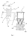
- the molding machine comprises a sand tank 1 for pressing the molding sand by the compressed air, which sand tank is equipped with compressed air supplying devices to fluidize the molding sand, a communicating tube 2 that communicates with the sand tank 1, a plurality of VP valves 5 (flow and pressure-control valves) as a plurality of adjusting means for adjusting the pressure and flow of the compressed air that are installed in parallel, and each outlet of which is connected to the communicating tube 2, and each inlet of which is connected to the source of the compressed air 4a through an auxiliary tube 3, VY valve (an electro-pneumatic proportional valve) 6, of which the supply and discharge ports are respectively connected to the source of the compressed air 4b and to the communication tube 2, a pressure-detecting means 7 that is provided on the sand tank 1 for detecting the pressure inside it, and a controller 8 that controls the operations
- An electro-pneumatic proportional valve is an electromagnetic valve that supplies compressed air at any pressure on instructions sent by a controller.
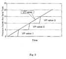
- the apparatus constructed as above first sets the operating conditions of a plurality of the VP valves 5 in the controller 8, and then supplies the compressed air from the VP valves 5 to control the pressure inside the sand tank 1 to cause it to be less than the appropriate pressure needed for filling the sand so as to have it correspond to the pattern shape in it. Then, under the control of the pressure-detecting means 7, it opens a plurality of the VP valves 5 in a stepwise manner, as well as operating the VY valve 6. In this way, it causes the pressure variation inside the sand tank 1 to correspond to a given ideal curve as in Fig. 2.
- FIG. 4 A schematic drawing of the sand molding machine of the present invention is shown in FIG. 4.
- FIG. 5 A graph that shows an ideal pressure curve inside the sand tank is shown in Fig. 5.
- Fig. 4 is formed almost same as Fig. 1.
- a controller 8 that controls the operations of the VP valves 5 and the VY valve 6 that is electrically connected to the VP valves 5 and the pressure-detecting means 7 and the VY valve 6, being constituted is different.
- the sand molding machine first sets the operating conditions of a plurality of the VP valves 5 and VY valve 6 and ideal pressure curve in the controller 8, and then supplies the compressed air from the VP valves 5 to control the pressure inside the sand tank 1 to cause it to be less than the appropriate pressure needed for filling the sand so as to have it correspond to the pattern shape in it, under the control of the pressure-detecting means 7, it opens and closes a plurality of the VP valves 5 in a stepwise manner up to the required maximum quantity, as well as operating the VY valve 6.
- the compressed air pressure curve supplied to sand tank 1 from VP valve 5 is shown in Fig. 6.
- the compressed air pressure curve supplied to sand tank 1 from VY valve 6 is shown in Fig. 7.
- the pressure curve in sand tank 1 is ideal as shown in Fig. 8.
- the synthesized pressure force curve (FIG. 8) in a sand tank is adjusted to extremely resemble an ideal pressure force curve (FIG. 5).
- the filling density of sand S of the upper part and the lower part is high, and central part with the pattern becomes low, and it is with a high quality and mold density is similar to the central part with the pattern and the lower part on a filling cavity when it is compressed afterwards.
- the pressure force to an adjusting means assumes 0.1- 0.3MPa
- the pressure force to an electro-pneumatic proportional valve can be assumed 0.5MPa degree.
- an electro-pneumatic proportional valve can just use factory air pressure in what can adjust for given pressure by electrical signal.
- the sand tank 1 has compressed air supplying devices to fluidize the molding sand and a function to pressurize the molding sand by blowed compressed air-
- the sand tank may be any construction in so far as it has a function to pressurize the molding sand by the compressed air. Furthermore, if you can obtain ideal sand filling, it is clear for a uniform mold to be possible with the compression after that by squeeze board B1 and B2.
- the molding sand of the present invention the green sand which designates the bentonite as the binder is most desirable. Also, the present invention can be used for sand filling not only to the molding flask which is the tight molding machine of the existence frame but also to the molding space which is the flaskless molding machine.
Landscapes
- Engineering & Computer Science (AREA)
- Mechanical Engineering (AREA)
- Casting Devices For Molds (AREA)
Abstract
Description
- The present invention relates to a sand-introducing-type sand molding machine that produces a sand mold by introducing molding sand into a molding flask or a molding space and by filling the space with it by using compressed air.
- There has been a blowing-type sand molding machine as one of this kind of machine. It generally comprises a blow head, a plurality of adjusting means for adjusting the pressure and flow of compressed air, wherein outlets of the means communicate with the blow head in parallel, a source of the compressed air that communicates with the inlets of the means, pressure-detecting means for detecting the pressure inside the blow head, and a controller that controls the operations of the adjusting means and the pressure detecting means that is electrically connected to them. The molding machine supplies compressed air into the blow head to let the molding sand in the blow head move into a molding flask or a molding space and fills it with the sand, and then makes a sand mold by compressing the molding sand that has been filled (see
Japanese Patent Laid-open Publication No. H06-277800 - The conventional blowing-type sand molding machine cannot adequately control the pressure inside the blow head so as to have it correspond to the pattern shape, because the supplied compressed air changes the pressure of its inside in a stepwise manner or slowly, as in Fig. 3. Accordingly, it does not fill enough molding sand into the molding flask, etc., or it wastes compressed air.
- The purpose of the present invention is to resolve these problems and to provide a sand-introducing-type sand molding machine that can adequately control the pressure-variation inside the sand tank to correspond to the pattern shape by supplying the compressed air.
- In order to accomplish this purpose, the sand-introducing-type sand molding machine of the present invention produces a sand mold by introducing molding sand into a molding flask or a molding space and filling the space with it by using compressed air. It comprises a sand tank for pressing the molding sand by the compressed air that is equipped with compressed air supplying devices to fluidize the molding sand, a communicating tube that communicates with the sand tank, a plurality of adjusting means for adjusting the pressure and flow of the compressed air which leading the sand tank that are installed in parallel, and each outlet of which is connected to the communicating tube, and each inlet of which is connected to the source of the compressed air, an electro-pneumatic proportional valve, of which the supply and discharge ports are respectively connected to a source of the compressed air and to the communicating tube, a pressure-detecting means that is provided on the sand tank for detecting the pressure inside it, and a controller that controls the operations of the plurality of the adjusting means and the electro-pneumatic proportional valve that is electrically connected to the plurality of the adjusting means and the pressure-detecting means and the electro-pneumatic proportional valve.
- Compressed air supplying devices to fluidize the molding sand, is the means that blows the compressed air to the inside of the sand tank, and the method is no object. For example, a parting plate of the permeable partitions off dual structure, i.e. the trunk wall of the main body of sand tank making pressure tank structure, and to have a hollow chamber is formed, it is possible with the thing which comprised this parting porous plate. As for this parting plate, a lot of through-holes which a mean pore size is 10-500µm, and is smaller than the particle size of the sand particle are provided and thickness can be comprised with the plastic board which is 5 - 20mm.
- Also, even the constitution that the parting plate which does not let air, and drilled a minute bore is possible.
- Also, the sand tank has at least a function to pressurize the top surface of the molding sand by the compressed air which the supplying devices is not put through.
- Also, even the pressure force of a source of the compressed air connected to the adjusting means and a source of the compressed air connected to the electro-pneumatic proportion valve may be adjusted by different or same pressure. In addition, these sources of the compressed air may be integrated into one.
- The apparatus constructed as above first sets the operating conditions of the adjusting means in the controller, and then supplies the compressed air from the adjusting means to control the pressure inside the sand tank to cause it to be less than the appropriate pressure needed for filling the sand so as to have it correspond to the pattern shape in it. Then, under the control of the pressure-detecting means, it opens the plurality of adjusting means in a stepwise manner or all at once, as well as operating the electro-pneumatic proportional valve. In this way, it causes the pressure variation inside the sand tank to correspond to a given ideal curve.
- Here, the given ideal pressure curve is a pressure curve to realize ideal filling density.
- For example, the filling density of the upper part and the lower part of mold become high and the central part of mold with the pattern becomes low in the ideal filling density on a filling cavity, and a mold density is similar within the central, upper and the lower part and mold quality is high when it is compressed afterwards.
- As is evident from these descriptions, the present invention is under the control of the pressure-detecting means, it opens the plurality of adjusting means in a stepwise manner or all at once, as well as operating the electro-pneumatic proportional valve. Thus it can achieve such a practical effect that the pressure variation inside the sand tank is caused to correspond to an ideal curve so as to correspond to the pattern shape.
-
- Fig. 1 is a schematic drawing of the sand molding machine of the present invention.
- Fig. 2 is a graph that shows a pressure variation inside the sand tank.
- Fig. 3 is a graph that shows a pressure variation inside a conventional blow head.
- Fig. 4 is a schematic drawing of the sand molding machine of the present invention.
- Fig. 5 is a graph that shows an ideal pressure curve inside the sand tank.
- Fig. 6 is a compressed air pressure curve supplied to
sand tank 1 fromVP valve 5. - Fig. 7 is a compressed air pressure curve supplied to
sand tank 1 fromVY valve 6. - Fig. 8 is a graph that shows a pressure curve inside the sand tank which is added up
- One embodiment of the sand introducing-type sand molding machine of the present invention is now explained in detail based on Figs. 1 and 2. As in Fig. 1, the molding machine comprises a
sand tank 1 for pressing the molding sand by the compressed air, which sand tank is equipped with compressed air supplying devices to fluidize the molding sand, a communicatingtube 2 that communicates with thesand tank 1, a plurality of VP valves 5 (flow and pressure-control valves) as a plurality of adjusting means for adjusting the pressure and flow of the compressed air that are installed in parallel, and each outlet of which is connected to the communicatingtube 2, and each inlet of which is connected to the source of the compressed air 4a through anauxiliary tube 3, VY valve (an electro-pneumatic proportional valve) 6, of which the supply and discharge ports are respectively connected to the source of thecompressed air 4b and to thecommunication tube 2, a pressure-detecting means 7 that is provided on thesand tank 1 for detecting the pressure inside it, and acontroller 8 that controls the operations of a plurality of theVP valves 5 and the pressure-detecting means 7 that is electrically connected to them. - An electro-pneumatic proportional valve is an electromagnetic valve that supplies compressed air at any pressure on instructions sent by a controller.
- The apparatus constructed as above first sets the operating conditions of a plurality of the
VP valves 5 in thecontroller 8, and then supplies the compressed air from theVP valves 5 to control the pressure inside thesand tank 1 to cause it to be less than the appropriate pressure needed for filling the sand so as to have it correspond to the pattern shape in it. Then, under the control of the pressure-detecting means 7, it opens a plurality of theVP valves 5 in a stepwise manner, as well as operating theVY valve 6. In this way, it causes the pressure variation inside thesand tank 1 to correspond to a given ideal curve as in Fig. 2. - Using this constitution of the invention that such a given ideal pressure curves can be pictured in, a method to realize ideal filling density is explained below. A schematic drawing of the sand molding machine of the present invention is shown in FIG. 4. A graph that shows an ideal pressure curve inside the sand tank is shown in Fig. 5.
- Fig. 4 is formed almost same as Fig. 1. A
controller 8 that controls the operations of theVP valves 5 and theVY valve 6 that is electrically connected to theVP valves 5 and the pressure-detecting means 7 and theVY valve 6, being constituted is different. - The sand molding machine first sets the operating conditions of a plurality of the
VP valves 5 andVY valve 6 and ideal pressure curve in thecontroller 8, and then supplies the compressed air from theVP valves 5 to control the pressure inside thesand tank 1 to cause it to be less than the appropriate pressure needed for filling the sand so as to have it correspond to the pattern shape in it, under the control of the pressure-detecting means 7, it opens and closes a plurality of theVP valves 5 in a stepwise manner up to the required maximum quantity, as well as operating theVY valve 6. - As a result of above, at the time of blow-filling up, the filling density of the sand S of the upper part and the lower part is high on a filling cavity, and central part with the pattern becomes low.
- In order to make the uniform density mold, it is necessary to obtain the ideal pressure curve inside the sand tank (FIG. 6) in order it blows and changes the sand tank internal pressure of filling up process, to do this filling up.
- The compressed air pressure curve supplied to
sand tank 1 fromVP valve 5 is shown in Fig. 6. Also, the compressed air pressure curve supplied tosand tank 1 fromVY valve 6 is shown in Fig. 7. In addition, these are synthesized, the pressure curve insand tank 1 is ideal as shown in Fig. 8. - The synthesized pressure force curve (FIG. 8) in a sand tank is adjusted to extremely resemble an ideal pressure force curve (FIG. 5).
- Pressure curve inside the sand tank (Fig. 8) which is synthesized is adjusted in order quite to resemble to ideal pressure curve (Fig. 5).
- As a result of this, the filling density of sand S of the upper part and the lower part is high, and central part with the pattern becomes low, and it is with a high quality and mold density is similar to the central part with the pattern and the lower part on a filling cavity when it is compressed afterwards.
- Note that the pressure force to an adjusting means assumes 0.1- 0.3MPa, the pressure force to an electro-pneumatic proportional valve can be assumed 0.5MPa degree. Here, an electro-pneumatic proportional valve can just use factory air pressure in what can adjust for given pressure by electrical signal.
- In this embodiment, the
sand tank 1 has compressed air supplying devices to fluidize the molding sand and a function to pressurize the molding sand by blowed compressed air- But the invention is not restricted to this construction. The sand tank may be any construction in so far as it has a function to pressurize the molding sand by the compressed air. Furthermore, if you can obtain ideal sand filling, it is clear for a uniform mold to be possible with the compression after that by squeeze board B1 and B2. - Also, as for the molding sand of the present invention, the green sand which designates the bentonite as the binder is most desirable. Also, the present invention can be used for sand filling not only to the molding flask which is the tight molding machine of the existence frame but also to the molding space which is the flaskless molding machine.
Claims (6)
- A sand-introducing-type sand molding machine for making a sand mold by introducing molding sand into a molding flask or a molding space and filling the space with it by using compressed air, comprising:a sand tank for pressing the molding sand by the compressed air that is equipped with compressed air supplying devices to fluidize the molding sand,a communicating tube that communicates with the sand tank,a plurality of adjusting means for adjusting the pressure and flow of the compressed air that are installed in parallel, and each outlet of which is connected to the communicating tube, and each inlet of which is connected to the source of the compressed air,an electro-pneumatic proportional valve, of which supply and discharge ports are respectively connected to the source of the compressed air and to the communicating tube,a pressure-detecting means for detecting the pressure inside the sand tank that is furnished on the sand tank, anda controller that controls the operations of the plurality of the adjusting means that is electrically connected to the plurality of the adjusting means and the pressure-detecting means.
- A sand-introducing-type sand molding machine for making a sand mold by introducing molding sand into a molding flask or a molding space and compacting a molding sand with it by using compressed air, comprising:a sand tank for pressing the molding sand by the compressed air that is equipped with compressed air supplying devices to fluidize the molding sand,a communicating tube that communicates with the sand tank,a plurality of adjusting means for adjusting the pressure and flow of the compressed air that are installed in parallel, and each outlet of which is connected to the communicating tube, and each inlet of which is connected to the source of the compressed air,an electro-pneumatic proportional valve, of which supply and discharge ports are respectively connected to the source of the compressed air and to the communicating tube,a pressure-detecting means for detecting the pressure inside the sand tank that is furnished on the sand tank, anda controller that controls the operations of the plurality of the adjusting means and the electro-pneumatic proportional valve that is electrically connected to the plurality of the adjusting means and the pressure-detecting means and the electro-pneumatic proportional valve.
- A sand-introducing-type sand molding machine, according to the claim 1 or 2, wherein the sand tank has at least a function to pressurize the top surface of the molding sand by the compressed air which the supplying devices is not put through.
- A sand-introducing-type sand molding machine, according to the claim 1 or 2, wherein the pressure force of a source of the compressed air connected to the adjusting means and the electro-pneumatic proportion valve being adjusted by different pressure
- A sand-introducing-type sand molding machine, according to the claim 1 or 2, wherein the pressure force of a source of the compressed air connected to the adjusting means and a source of the compressed air connected to the electro-pneumatic proportion valve being adjusted by same pressure.
- A sand-introducing-type sand molding machine, according to the claim 1 or 2, wherein a source of the compressed air connected to the adjusting means and a source of the compressed air connected to the electro-pneumatic proportion valve being integrated into one.
Applications Claiming Priority (2)
| Application Number | Priority Date | Filing Date | Title |
|---|---|---|---|
| JP2007006482 | 2007-01-16 | ||
| JP2007132487 | 2007-05-18 |
Publications (2)
| Publication Number | Publication Date |
|---|---|
| EP1857201A1 true EP1857201A1 (en) | 2007-11-21 |
| EP1857201B1 EP1857201B1 (en) | 2017-11-29 |
Family
ID=38441846
Family Applications (1)
| Application Number | Title | Priority Date | Filing Date |
|---|---|---|---|
| EP07012739.4A Active EP1857201B1 (en) | 2007-01-16 | 2007-06-28 | Sand-introducing-type sand molding machine |
Country Status (7)
| Country | Link |
|---|---|
| US (1) | US20080169079A1 (en) |
| EP (1) | EP1857201B1 (en) |
| JP (1) | JP4697609B2 (en) |
| KR (1) | KR101106868B1 (en) |
| BR (1) | BRPI0720949B8 (en) |
| MX (1) | MX2009007563A (en) |
| WO (1) | WO2008087758A1 (en) |
Families Citing this family (2)
| Publication number | Priority date | Publication date | Assignee | Title |
|---|---|---|---|---|
| CN114700468A (en) * | 2022-04-01 | 2022-07-05 | 朱兴丰 | Automatic manufacturing equipment for composite sand mold for cast iron |
| CN115007798A (en) * | 2022-06-15 | 2022-09-06 | 安徽汉扬精密机械有限公司 | Full-automatic horizontal sand casting machine and working method thereof |
Citations (5)
| Publication number | Priority date | Publication date | Assignee | Title |
|---|---|---|---|---|
| JPH06277800A (en) * | 1993-03-26 | 1994-10-04 | Sintokogio Ltd | BLOWING MOLD MOLDING METHOD AND DEVICE THEREOF |
| JPH1099941A (en) * | 1996-10-01 | 1998-04-21 | Metal Eng Kk | Mold making method and apparatus |
| EP0960669A1 (en) * | 1998-05-23 | 1999-12-01 | Dipl.-Ing. Laempe GmbH | Method and apparatus for the production of foundry moulding parts of sand |
| US6253827B1 (en) * | 1998-10-28 | 2001-07-03 | Sintokogio, Ltd. | Method of compressing molding sand using independently controlled gas guiding pipes |
| US20010009184A1 (en) * | 1998-03-27 | 2001-07-26 | Sintokogio, Ltd. | Blow molding machine |
Family Cites Families (8)
| Publication number | Priority date | Publication date | Assignee | Title |
|---|---|---|---|---|
| US3965961A (en) * | 1971-09-23 | 1976-06-29 | Dansk Industri Syndikat A/S | Method of operating automatic mold part producing apparatus |
| JPH0515415Y2 (en) * | 1988-10-07 | 1993-04-22 | ||
| DE4092542C2 (en) * | 1990-03-20 | 1993-11-18 | Dansk Ind Syndikat | Process for producing a series of casting molds or molded parts and device for carrying out the process |
| WO2001019546A1 (en) * | 1999-09-16 | 2001-03-22 | Sintokogio, Ltd. | Blow molding method for superplastic materials and system |
| CN1261256C (en) | 1999-11-04 | 2006-06-28 | 新东工业株式会社 | Molding device for molding method or sand mold |
| EP1184106B1 (en) * | 2000-02-17 | 2013-07-17 | Sintokogio, Ltd. | Method and device for filling casting sand |
| JP2002018552A (en) * | 2000-07-04 | 2002-01-22 | Sintokogio Ltd | Casting sand injection device |
| JP3729197B2 (en) | 2001-08-06 | 2005-12-21 | 新東工業株式会社 | Method and system for monitoring a mold making machine |
-
2007
- 2007-06-19 JP JP2007160932A patent/JP4697609B2/en active Active
- 2007-06-28 EP EP07012739.4A patent/EP1857201B1/en active Active
- 2007-07-04 BR BRPI0720949A patent/BRPI0720949B8/en active IP Right Grant
- 2007-07-04 KR KR1020097016743A patent/KR101106868B1/en not_active Expired - Fee Related
- 2007-07-04 MX MX2009007563A patent/MX2009007563A/en not_active Application Discontinuation
- 2007-07-04 WO PCT/JP2007/063764 patent/WO2008087758A1/en not_active Ceased
- 2007-07-05 US US11/822,372 patent/US20080169079A1/en not_active Abandoned
Patent Citations (5)
| Publication number | Priority date | Publication date | Assignee | Title |
|---|---|---|---|---|
| JPH06277800A (en) * | 1993-03-26 | 1994-10-04 | Sintokogio Ltd | BLOWING MOLD MOLDING METHOD AND DEVICE THEREOF |
| JPH1099941A (en) * | 1996-10-01 | 1998-04-21 | Metal Eng Kk | Mold making method and apparatus |
| US20010009184A1 (en) * | 1998-03-27 | 2001-07-26 | Sintokogio, Ltd. | Blow molding machine |
| EP0960669A1 (en) * | 1998-05-23 | 1999-12-01 | Dipl.-Ing. Laempe GmbH | Method and apparatus for the production of foundry moulding parts of sand |
| US6253827B1 (en) * | 1998-10-28 | 2001-07-03 | Sintokogio, Ltd. | Method of compressing molding sand using independently controlled gas guiding pipes |
Also Published As
| Publication number | Publication date |
|---|---|
| JP4697609B2 (en) | 2011-06-08 |
| BRPI0720949A2 (en) | 2014-03-18 |
| KR20090101488A (en) | 2009-09-28 |
| JP2009000690A (en) | 2009-01-08 |
| KR101106868B1 (en) | 2012-01-19 |
| US20080169079A1 (en) | 2008-07-17 |
| BRPI0720949B8 (en) | 2016-10-11 |
| MX2009007563A (en) | 2009-08-13 |
| EP1857201B1 (en) | 2017-11-29 |
| WO2008087758A1 (en) | 2008-07-24 |
| BRPI0720949B1 (en) | 2016-03-29 |
Similar Documents
| Publication | Publication Date | Title |
|---|---|---|
| KR101652883B1 (en) | Mold forming apparatus | |
| TW471985B (en) | Method and device for filling molding sand | |
| JP2010515573A (en) | Sand introduction apparatus using air, mold making method and mold making apparatus | |
| JP5076670B2 (en) | Frameless mold making machine | |
| EP1857201B1 (en) | Sand-introducing-type sand molding machine | |
| CA2588049A1 (en) | Apparatus and method for producing casting mold | |
| US7594531B2 (en) | Molding machine | |
| JP4203840B2 (en) | Casting sand filling method and apparatus in frameless horizontal split mold making machine | |
| JP4379795B2 (en) | Casting sand filling method | |
| JP3092764B2 (en) | Blow molding method | |
| CN109070195A (en) | Removable flask molding machine | |
| CN101600525A (en) | Molding sand introducing-type sand molding device | |
| CN103492103A (en) | Core sand filling apparatus and core sand filling method in core making machine | |
| EP0802004B1 (en) | A method of filling cores with molding sand | |
| US20130118703A1 (en) | Method for Making Upper and Lower Molds and an Apparatus Therefor | |
| US2847736A (en) | Device for making sand molds for metal casting | |
| JP2845390B2 (en) | Compressed air supply method in mold making apparatus | |
| JP3332214B2 (en) | Blow molding machine | |
| KR0180355B1 (en) | Pressurization Device of Vacuum Mold | |
| JP2001225148A (en) | Method of injecting casting sand into casting flask | |
| CN114713777A (en) | Core shooting device of ultra-large core shooting machine and control method thereof | |
| JPH04200956A (en) | Method for molding casting mold | |
| JP3441065B2 (en) | Mold molding method and molding apparatus | |
| JPH0710828Y2 (en) | Compressed air blowing device in green molding equipment | |
| KR20220112130A (en) | Core machine sand filler |
Legal Events
| Date | Code | Title | Description |
|---|---|---|---|
| PUAI | Public reference made under article 153(3) epc to a published international application that has entered the european phase |
Free format text: ORIGINAL CODE: 0009012 |
|
| AK | Designated contracting states |
Kind code of ref document: A1 Designated state(s): AT BE BG CH CY CZ DE DK EE ES FI FR GB GR HU IE IS IT LI LT LU LV MC MT NL PL PT RO SE SI SK TR |
|
| AX | Request for extension of the european patent |
Extension state: AL BA HR MK YU |
|
| 17P | Request for examination filed |
Effective date: 20080206 |
|
| 17Q | First examination report despatched |
Effective date: 20080304 |
|
| AKX | Designation fees paid |
Designated state(s): AT BE BG CH CY CZ DE DK EE ES FI FR GB GR HU IE IS IT LI LT LU LV MC MT NL PL PT RO SE SI SK TR |
|
| GRAP | Despatch of communication of intention to grant a patent |
Free format text: ORIGINAL CODE: EPIDOSNIGR1 |
|
| STAA | Information on the status of an ep patent application or granted ep patent |
Free format text: STATUS: GRANT OF PATENT IS INTENDED |
|
| INTG | Intention to grant announced |
Effective date: 20170714 |
|
| GRAS | Grant fee paid |
Free format text: ORIGINAL CODE: EPIDOSNIGR3 |
|
| GRAA | (expected) grant |
Free format text: ORIGINAL CODE: 0009210 |
|
| STAA | Information on the status of an ep patent application or granted ep patent |
Free format text: STATUS: THE PATENT HAS BEEN GRANTED |
|
| AK | Designated contracting states |
Kind code of ref document: B1 Designated state(s): AT BE BG CH CY CZ DE DK EE ES FI FR GB GR HU IE IS IT LI LT LU LV MC MT NL PL PT RO SE SI SK TR |
|
| REG | Reference to a national code |
Ref country code: GB Ref legal event code: FG4D |
|
| REG | Reference to a national code |
Ref country code: CH Ref legal event code: EP |
|
| REG | Reference to a national code |
Ref country code: AT Ref legal event code: REF Ref document number: 949920 Country of ref document: AT Kind code of ref document: T Effective date: 20171215 |
|
| REG | Reference to a national code |
Ref country code: IE Ref legal event code: FG4D |
|
| REG | Reference to a national code |
Ref country code: DE Ref legal event code: R096 Ref document number: 602007053188 Country of ref document: DE |
|
| REG | Reference to a national code |
Ref country code: NL Ref legal event code: MP Effective date: 20171129 |
|
| REG | Reference to a national code |
Ref country code: LT Ref legal event code: MG4D |
|
| REG | Reference to a national code |
Ref country code: AT Ref legal event code: MK05 Ref document number: 949920 Country of ref document: AT Kind code of ref document: T Effective date: 20171129 |
|
| PG25 | Lapsed in a contracting state [announced via postgrant information from national office to epo] |
Ref country code: LT Free format text: LAPSE BECAUSE OF FAILURE TO SUBMIT A TRANSLATION OF THE DESCRIPTION OR TO PAY THE FEE WITHIN THE PRESCRIBED TIME-LIMIT Effective date: 20171129 Ref country code: FI Free format text: LAPSE BECAUSE OF FAILURE TO SUBMIT A TRANSLATION OF THE DESCRIPTION OR TO PAY THE FEE WITHIN THE PRESCRIBED TIME-LIMIT Effective date: 20171129 Ref country code: SE Free format text: LAPSE BECAUSE OF FAILURE TO SUBMIT A TRANSLATION OF THE DESCRIPTION OR TO PAY THE FEE WITHIN THE PRESCRIBED TIME-LIMIT Effective date: 20171129 Ref country code: ES Free format text: LAPSE BECAUSE OF FAILURE TO SUBMIT A TRANSLATION OF THE DESCRIPTION OR TO PAY THE FEE WITHIN THE PRESCRIBED TIME-LIMIT Effective date: 20171129 |
|
| PG25 | Lapsed in a contracting state [announced via postgrant information from national office to epo] |
Ref country code: BG Free format text: LAPSE BECAUSE OF FAILURE TO SUBMIT A TRANSLATION OF THE DESCRIPTION OR TO PAY THE FEE WITHIN THE PRESCRIBED TIME-LIMIT Effective date: 20180228 Ref country code: LV Free format text: LAPSE BECAUSE OF FAILURE TO SUBMIT A TRANSLATION OF THE DESCRIPTION OR TO PAY THE FEE WITHIN THE PRESCRIBED TIME-LIMIT Effective date: 20171129 Ref country code: AT Free format text: LAPSE BECAUSE OF FAILURE TO SUBMIT A TRANSLATION OF THE DESCRIPTION OR TO PAY THE FEE WITHIN THE PRESCRIBED TIME-LIMIT Effective date: 20171129 Ref country code: GR Free format text: LAPSE BECAUSE OF FAILURE TO SUBMIT A TRANSLATION OF THE DESCRIPTION OR TO PAY THE FEE WITHIN THE PRESCRIBED TIME-LIMIT Effective date: 20180301 |
|
| PG25 | Lapsed in a contracting state [announced via postgrant information from national office to epo] |
Ref country code: NL Free format text: LAPSE BECAUSE OF FAILURE TO SUBMIT A TRANSLATION OF THE DESCRIPTION OR TO PAY THE FEE WITHIN THE PRESCRIBED TIME-LIMIT Effective date: 20171129 |
|
| PG25 | Lapsed in a contracting state [announced via postgrant information from national office to epo] |
Ref country code: CZ Free format text: LAPSE BECAUSE OF FAILURE TO SUBMIT A TRANSLATION OF THE DESCRIPTION OR TO PAY THE FEE WITHIN THE PRESCRIBED TIME-LIMIT Effective date: 20171129 Ref country code: CY Free format text: LAPSE BECAUSE OF FAILURE TO SUBMIT A TRANSLATION OF THE DESCRIPTION OR TO PAY THE FEE WITHIN THE PRESCRIBED TIME-LIMIT Effective date: 20171129 Ref country code: EE Free format text: LAPSE BECAUSE OF FAILURE TO SUBMIT A TRANSLATION OF THE DESCRIPTION OR TO PAY THE FEE WITHIN THE PRESCRIBED TIME-LIMIT Effective date: 20171129 Ref country code: SK Free format text: LAPSE BECAUSE OF FAILURE TO SUBMIT A TRANSLATION OF THE DESCRIPTION OR TO PAY THE FEE WITHIN THE PRESCRIBED TIME-LIMIT Effective date: 20171129 Ref country code: DK Free format text: LAPSE BECAUSE OF FAILURE TO SUBMIT A TRANSLATION OF THE DESCRIPTION OR TO PAY THE FEE WITHIN THE PRESCRIBED TIME-LIMIT Effective date: 20171129 |
|
| REG | Reference to a national code |
Ref country code: DE Ref legal event code: R097 Ref document number: 602007053188 Country of ref document: DE |
|
| PG25 | Lapsed in a contracting state [announced via postgrant information from national office to epo] |
Ref country code: IT Free format text: LAPSE BECAUSE OF FAILURE TO SUBMIT A TRANSLATION OF THE DESCRIPTION OR TO PAY THE FEE WITHIN THE PRESCRIBED TIME-LIMIT Effective date: 20171129 Ref country code: RO Free format text: LAPSE BECAUSE OF FAILURE TO SUBMIT A TRANSLATION OF THE DESCRIPTION OR TO PAY THE FEE WITHIN THE PRESCRIBED TIME-LIMIT Effective date: 20171129 Ref country code: PL Free format text: LAPSE BECAUSE OF FAILURE TO SUBMIT A TRANSLATION OF THE DESCRIPTION OR TO PAY THE FEE WITHIN THE PRESCRIBED TIME-LIMIT Effective date: 20171129 |
|
| PLBE | No opposition filed within time limit |
Free format text: ORIGINAL CODE: 0009261 |
|
| STAA | Information on the status of an ep patent application or granted ep patent |
Free format text: STATUS: NO OPPOSITION FILED WITHIN TIME LIMIT |
|
| 26N | No opposition filed |
Effective date: 20180830 |
|
| PG25 | Lapsed in a contracting state [announced via postgrant information from national office to epo] |
Ref country code: SI Free format text: LAPSE BECAUSE OF FAILURE TO SUBMIT A TRANSLATION OF THE DESCRIPTION OR TO PAY THE FEE WITHIN THE PRESCRIBED TIME-LIMIT Effective date: 20171129 |
|
| REG | Reference to a national code |
Ref country code: CH Ref legal event code: PL |
|
| GBPC | Gb: european patent ceased through non-payment of renewal fee |
Effective date: 20180628 |
|
| REG | Reference to a national code |
Ref country code: BE Ref legal event code: MM Effective date: 20180630 |
|
| PG25 | Lapsed in a contracting state [announced via postgrant information from national office to epo] |
Ref country code: LU Free format text: LAPSE BECAUSE OF NON-PAYMENT OF DUE FEES Effective date: 20180628 Ref country code: MC Free format text: LAPSE BECAUSE OF FAILURE TO SUBMIT A TRANSLATION OF THE DESCRIPTION OR TO PAY THE FEE WITHIN THE PRESCRIBED TIME-LIMIT Effective date: 20171129 |
|
| REG | Reference to a national code |
Ref country code: IE Ref legal event code: MM4A |
|
| PG25 | Lapsed in a contracting state [announced via postgrant information from national office to epo] |
Ref country code: IE Free format text: LAPSE BECAUSE OF NON-PAYMENT OF DUE FEES Effective date: 20180628 Ref country code: CH Free format text: LAPSE BECAUSE OF NON-PAYMENT OF DUE FEES Effective date: 20180630 Ref country code: FR Free format text: LAPSE BECAUSE OF NON-PAYMENT OF DUE FEES Effective date: 20180630 Ref country code: GB Free format text: LAPSE BECAUSE OF NON-PAYMENT OF DUE FEES Effective date: 20180628 Ref country code: LI Free format text: LAPSE BECAUSE OF NON-PAYMENT OF DUE FEES Effective date: 20180630 |
|
| PG25 | Lapsed in a contracting state [announced via postgrant information from national office to epo] |
Ref country code: BE Free format text: LAPSE BECAUSE OF NON-PAYMENT OF DUE FEES Effective date: 20180630 |
|
| PG25 | Lapsed in a contracting state [announced via postgrant information from national office to epo] |
Ref country code: MT Free format text: LAPSE BECAUSE OF NON-PAYMENT OF DUE FEES Effective date: 20180628 |
|
| PG25 | Lapsed in a contracting state [announced via postgrant information from national office to epo] |
Ref country code: PT Free format text: LAPSE BECAUSE OF FAILURE TO SUBMIT A TRANSLATION OF THE DESCRIPTION OR TO PAY THE FEE WITHIN THE PRESCRIBED TIME-LIMIT Effective date: 20171129 Ref country code: HU Free format text: LAPSE BECAUSE OF FAILURE TO SUBMIT A TRANSLATION OF THE DESCRIPTION OR TO PAY THE FEE WITHIN THE PRESCRIBED TIME-LIMIT; INVALID AB INITIO Effective date: 20070628 |
|
| PG25 | Lapsed in a contracting state [announced via postgrant information from national office to epo] |
Ref country code: IS Free format text: LAPSE BECAUSE OF FAILURE TO SUBMIT A TRANSLATION OF THE DESCRIPTION OR TO PAY THE FEE WITHIN THE PRESCRIBED TIME-LIMIT Effective date: 20180329 |
|
| PGFP | Annual fee paid to national office [announced via postgrant information from national office to epo] |
Ref country code: DE Payment date: 20260622 Year of fee payment: 20 |
|
| PGFP | Annual fee paid to national office [announced via postgrant information from national office to epo] |
Ref country code: TR Payment date: 20260623 Year of fee payment: 20 |