EP1856954B1 - Glow-switch starter, lighting device and lighting system therewith, and use thereof - Google Patents
Glow-switch starter, lighting device and lighting system therewith, and use thereof Download PDFInfo
- Publication number
- EP1856954B1 EP1856954B1 EP06710937A EP06710937A EP1856954B1 EP 1856954 B1 EP1856954 B1 EP 1856954B1 EP 06710937 A EP06710937 A EP 06710937A EP 06710937 A EP06710937 A EP 06710937A EP 1856954 B1 EP1856954 B1 EP 1856954B1
- Authority
- EP
- European Patent Office
- Prior art keywords
- glow
- lamp
- gas filling
- lighting device
- ionizable gas
- Prior art date
- Legal status (The legal status is an assumption and is not a legal conclusion. Google has not performed a legal analysis and makes no representation as to the accuracy of the status listed.)
- Expired - Lifetime
Links
Images


Classifications
-
- H—ELECTRICITY
- H05—ELECTRIC TECHNIQUES NOT OTHERWISE PROVIDED FOR
- H05B—ELECTRIC HEATING; ELECTRIC LIGHT SOURCES NOT OTHERWISE PROVIDED FOR; CIRCUIT ARRANGEMENTS FOR ELECTRIC LIGHT SOURCES, IN GENERAL
- H05B41/00—Circuit arrangements or apparatus for igniting or operating discharge lamps
- H05B41/02—Details
- H05B41/04—Starting switches
- H05B41/06—Starting switches thermal only
- H05B41/08—Starting switches thermal only heated by glow discharge
Definitions
- the present invention relates, in a first aspect, to a lighting device comprising:
- a glow-switch starter is well known in the art, and is in common use for igniting e.g. tubular fluorescent lamps. Its functioning is deemed well understood by the person skilled in the art, and will only be elucidated upon when this is relevant for understanding the invention.
- US 6,657,389 discloses a glow discharge lamp for use as a glow starter for discharge lamps.
- the gas filling consists of neon as a primary constituent (at least 40%) and at least one of krypton, xenon and argon, while helium, hydrogen or organic gas may be added.
- Gas discharge lamps require a current limiter to prevent their destruction after ignition.
- this current limiter comprises a ballast with a large coil, connected in series with the discharge lamp. When the discharge lamp is operating, the current flows through the discharge lamp, the electrodes thereof and through the ballast. Even with carefully selected components, this will cause energy losses, due to resistive heating, which may amount to 10-15% or even more of the total energy consumption.
- One way of increasing the efficiency is by increasing the lamp voltage, i.e. the voltage over the discharge, while at the same time decreasing the lamp current, in order to maintain the total lamp power at a constant level.
- Increasing the lamp voltage is limited due to a number of factors, such as of course the mains supply voltage.
- the mains supply voltage may e.g. be increased by using a three phase wiring of the normal 230-240V mains supply voltage. This offers an increased nominal supply voltage of about 400V. Simply replacing the 230-240V mains connection by a three phase (400V) connection however causes problems when operating the lamp. The lamp may show blinking, the starter life may be reduced, etc., which is undesirable.
- this object is achieved with a lighting device according to claim 1.
- the inventor has discovered that at least part of the problems relating to more unreliable lamp operation with common starters and at increased lamp voltage are due to parallel glowing of the starter during operation of the gas discharge lamp, in the steady state. Said parallel glowing is caused by the lamp voltage, which is also substantially supplied to the starter. This voltage across the starter reaches a reignition peak during reignition of the lamp, after the supply voltage has crossed the zero, and which lasts a certain period of time. Especially during the reignition peak, the voltage across the starter is so high that the glowing of the starter caused thereby heats the bimetal switch sufficiently to cause closing thereof, which in turn causes extinction of the lamp. This is of course undesirable.
- the ionizable gas filling in the glow-switch starter of a lighting device according to the present invention has a total pressure of between 3 and 60 mbar at room temperature and comprises neon or neon with at least one of the group of helium, krypton, xenon, nitrogen and hydrogen, or a mixture thereof, wherein argon is present in the ionizable gas filling in a relative amount of less than 10%, or preferably less than 2%,
- the total pressure is at least 5 mbar. Tests have shown that such a minimum pressure more reliably causes the peak voltage to remain below about 2-2.5 kilovolts, which is desirable to prevent cold ignition of the lamp or breakdown of a parallel capacitor. Even more preferably, the total pressure is at least 10 mbar. Note that 1 mbar is about 101 Pa.
- neon may be a useful gas for use with the filling, and is hence not excluded, in some cases its presence should be reduced.
- the presence of neon may affect the development of an appropriate reignition peak voltage, and should thus be avoided in those cases in which lamp operation critically depends on this reignition peak.
- the ionizable gas filling substantially comprises helium.
- the term “substantially” is intended to mean at least 90%, while allowing for admixture of other gases.
- Helium is a suitable gas for use as an ionizable medium or gas according to the invention. Furthermore, it has a property that it easily leaks away through the wall of the starter, which may give rise to an increase in peak reignition voltage. This may be helpful to support ignition of ageing lamps.
- the ionizable gas filling substantially comprises krypton, at a pressure of between 3 and 10 mbar. In yet another embodiment, the ionizable gas filling substantially comprises xenon, at a pressure of between 3 and 15 mbar. Again, the term “substantially” is intended to mean at least 90%. Also, mixtures of the two gases, at a total pressure of between 3 and 10 mbar are possible.
- the ionizable gas filling comprises helium and at least one of xenon, krypton, hydrogen, nitrogen or a mixture thereof, a ratio of helium : (xenon, krypton, hydrogen, nitrogen or the mixture thereof) being between 1.5 : 1, and 200 : 1.
- Admixture to helium of xenon, krypton, hydrogen or a mixture thereof supports ionization of the gas filling, because of the much lower ionization potential of the admixture gases. This also prevents to a certain degree the escape of ionized helium, since in the mixture the helium will be hardly become ionized.
- the gas pressure is between 10 and 35 mbar. Tests have shown that this pressure range is advantageous to obtain the desired effect according to the invention. This range holds generally, but in particular for the helium with admixtures.
- the ionizable gas filling substantially comprises hydrogen or nitrogen, or a mixture thereof. It turns out that even with these gases, a suitable ignition behavior may be obtained.
- the supply voltage is intended to mean the voltage actually used in operating the starter and/or the discharge lamp, and not the supply voltage in cases where some three phase power connection is first transformed or wired down to standard 230-240V mains. In more particular cases, the supply voltage is sufficient to cause a lamp voltage across the lamp, in steady state, which is at least 230V.
- the ionizable gas filling is selected such that, when the gas discharge lamp is operating in a steady state, the glow-switch starter carries an average parallel glow current of less than 4 milliamperes, and preferably at most about 2.5 mA. This has proven a useful current range.
- the gas discharge lamp is a low-pressure mercury vapor lamp, more particularly a UV fluorescent lamp.
- the invention allows the design of a more energy efficient lighting device.
- the lamp power may be increased, by taking e.g. a similar lamp current but a higher lamp voltage, for example through taking a longer discharge vessel.
- Higher lamp power may be used to reduce the number of lamps in order to obtain a certain lighting level. It is also possible to increase the lighting intensity, which is especially desirable in the case of UV-lighting, such as in tanning parlors.
- the actual supply voltage for the (UV) lighting part is again the 230-240V mains.
- the actual supply voltage for the lighting part is the full three-phase mains, or nominally about 400V. Since tanning device designers require ever more power, the present invention is able to provide that extra power, but still with the use of a simple glow-switch starter.
- the invention relates to the use of an ionizable gas filling of a glow-switch starter for keeping the glow switch starter open under the influence of parallel glowing during steady-state lamp operation at increased lamp voltage.
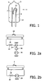
- Fig. 1 shows a schematical glow-switch starter 1 for use in a lighting device according to the invention.
- 3 denotes a substantially gas-tight housing with a filling 5 of ionizable medium, a first electrode 7 and a second electrode 9 with a bimetal part 11.
- 13 denotes a pinch, where the housing 3 is sealed.
- the housing 3 is made of vitreous material, which has good sealing properties. Furthermore, in many cases such vitreous materials are transparent, which allows ambient light to promote ionization of the medium.
- the electrodes 7 and 9 may be made of any suitable material known to the skilled person, such as a nickel-iron alloy. At least one of the electrodes may be provided with a gettering means (not shown), to reduce impurities in the gas filling 5. At least one of the electrodes, such as electrode 9, is provided with, or may be comprised of, a bimetallic element 11. In a non-operative condition, the bimetallic element is provided in a spaced-apart position with respect to the opposite electrode 7.
- a supply voltage is supplied over the starter 1, which causes a glow discharge of the gas filling 5, from electrode 7 to electrode 9 and the bimetal 11. The discharge heats the bimetal, which changes shape until it contacts the opposite electrode 7, upon which the glow discharge is extinguished. Thereupon, the bimetal 11 cools down, and the contact is broken. The resulting voltage surge from a lamp ballast can now ignite the lamp.
- the bimetal switch as a whole comprises the bimetal element 11, as well as the electrodes 7 and 9.
- the bimetal element 11 is electrically connected to electrode 9, and after heating contacts the opposite electrode 7. Both electrodes 7 and 9 either are led through the pinch 13 of the housing 3, or are each connected to a lead there through. Such details are deemed familiar to the skilled person.
- the properties of the gas filling 5 are important in order to determine the glow time and the ignition voltage.
- the glow current should be less than 3.5 mA, preferably between 0.5 and 2 mA.
- the glow time should not be too long, since this prevents sufficient heating of the electrodes of the discharge lamp. Taking for example the helium60/xenon40 mixture, then pressures up to about 35 mbar are well acceptable, not excluding other pressures.
- the pure xenon gas filling b) works well up to about 15 mbar, again not excluding other pressures.
- the filling c) is less useful, due to a low ignition voltage and a high glow current.
- Fig. 2a schematically shows a prior art lighting system
- Fig. 2b schematically shows a lighting system according to the invention.
- 18 denotes a prior art glow-switch starter
- 20 is a gas discharge lamp
- 22 is a choke or ballast
- 24 denotes a 230V supply voltage
- a three-phase mains voltage is denoted by 26, which is rewired at box or circuit 28 to become the 230V supply voltage.
- the gas discharge lamp 20 may be a fluorescent lamp, such as a UV tube, e.g. of a tanning device, or a TL lamp.
- the ballast 22 is a current limiter for the fluorescent lamp 20, and is selected according to the power rating of the lamp 20.
- the actual supply voltage is 230V, which limits the lamp voltage, in practice to about 3/4 of said supply voltage. This in turn limits the lamp efficiency and causes relatively high energy losses in the ballast 22 and/or electrodes of the lamp 20.
- the total power consumption is such (sometimes more than 10 kW) that three-phase mains is required as a power supply. Nevertheless, in the device itself, the supply voltage is reduced to 230V.
- Fig. 2b schematically shows a lighting device according to the invention. Similar parts are denoted by the same reference numerals.
- a glow-switch starter according to the present invention is denoted by reference numeral 1.
- the actual supply voltage in the device according to Fig. 2b is the full three phase supply voltage, of nominally about 400V. This allows a higher lamp voltage, and subsequently a higher energy efficiency, both through less losses in the ballast 22 and through a more efficient discharge in the lamp 20. Since the voltages across the starter 1 are also different from the prior art situation, the starter 1 should be modified, according to the invention.
- Fig. 3 shows a diagrammatical time-voltage graph for a typical low-pressure discharge lamp on a 400 V mains. It can be clearly seen that there is a very narrow ignition peak, at the beginning of each curve.
- the glow-switch starter will (parallel) glow most during this narrow peak, since (parallel) glowing is much more than linearly dependent of voltage. Hence parallel glowing during the rest of each curve is negligible. It is thus a task of the starter to remain open even under the influence of parallel glowing during the narrow ignition peak. Of course, even though the parallel glowing is much less during the rest of the curve, heating of the starter should still be insufficient to close the switch.
- FIG 4 schematically shows a part of a lighting device according to the invention, comprising a tanning device.
- the tanning device comprises ten fluorescent lamps 30 for generating UV-A and UV-B light, of which only one lamp is shown in Figure 4 .
- the distance d between two neighboring fluorescent lamps is typically 40 - 45 mm. In another embodiment a different number of fluorescent lamps may be present, and/or a different distance d between two neighboring lamps can be used.
- the fluorescent lamps are coupled to a glow-switch starter, a ballast and a three phase main voltage power supply, as shown in Figure 2b , not shown in Figure 4 .
- the three-phase main voltage power supply may be a single power supply for all ten fluorescent lamps.
- the tanning device further comprises a reflector 32, for reflecting UV light generated by the fluorescent lamps 30, during use of the tanning device, into the direction of the person that uses the tanning device.
- the reflector 32 has a dedicated shape in order to generate a homogeneous light distribution. In another embodiment a different reflector shape can be used in order to generate a homogeneous light distribution.
- the fluorescent lamps typically comprise a mixture of helium and neon, a ratio of helium : neon being 1 : 3, but in another embodiment a different ratio can be used.
- the fluorescent lamps are typically operated at a lamp voltage of 280 - 320 V, and a lamp current of 1.4 - 1.8 A.
- the fluorescent lamps can be operated at a higher lamp voltage compared to known tanning devices, allowing the lamp power to be increased. As a result of the higher lamp power, the number of fluorescent lamps in the tanning device is reduced compared to known tanning devices. For example, in a known tanning device typically twenty fluorescent lamps are present, typically operable at a lamp voltage of 230 - 240 V.
- the higher efficiency of the tanning device according to the invention leads to a lower energy consumption.
- the number of ballasts and starters as well as the wiring is also reduced in the tanning device according to the invention, due to the lower number of fluorescent lamps, the component costs are reduced as well.
Landscapes
- Discharge Lamp (AREA)
- Circuit Arrangements For Discharge Lamps (AREA)
- Discharge Lamps And Accessories Thereof (AREA)
- Breeding Of Plants And Reproduction By Means Of Culturing (AREA)
- Magnetic Ceramics (AREA)
- Preparation Of Compounds By Using Micro-Organisms (AREA)
Abstract
Description
- The present invention relates, in a first aspect, to a lighting device comprising:
- a gas discharge lamp (20);
- a ballast (22) suitable for said discharge lamp (20);
- a three-phase mains voltage power supply (26) connected to the ballast and the gas discharge lamp and able to supply a nominal supply voltage of at least 250 Vrms, and preferably at least nominally 400V to the ballast and the gas discharge lamp; and
- a glow-switch starter (1) comprising:
- a substantially gas-tight housing (3),
- an ionizable gas filling (5),
- at least two electrodes (7, 9) and
- at least one bimetal switching device (11).
- A glow-switch starter is well known in the art, and is in common use for igniting e.g. tubular fluorescent lamps. Its functioning is deemed well understood by the person skilled in the art, and will only be elucidated upon when this is relevant for understanding the invention. For example,
US 6,657,389 discloses a glow discharge lamp for use as a glow starter for discharge lamps. The gas filling consists of neon as a primary constituent (at least 40%) and at least one of krypton, xenon and argon, while helium, hydrogen or organic gas may be added. - A problem in the art, relating to glow-switch starters, is the following. Gas discharge lamps require a current limiter to prevent their destruction after ignition. Very often, this current limiter comprises a ballast with a large coil, connected in series with the discharge lamp. When the discharge lamp is operating, the current flows through the discharge lamp, the electrodes thereof and through the ballast. Even with carefully selected components, this will cause energy losses, due to resistive heating, which may amount to 10-15% or even more of the total energy consumption.
- One way of increasing the efficiency is by increasing the lamp voltage, i.e. the voltage over the discharge, while at the same time decreasing the lamp current, in order to maintain the total lamp power at a constant level. Increasing the lamp voltage is limited due to a number of factors, such as of course the mains supply voltage.
- The mains supply voltage may e.g. be increased by using a three phase wiring of the normal 230-240V mains supply voltage. This offers an increased nominal supply voltage of about 400V. Simply replacing the 230-240V mains connection by a three phase (400V) connection however causes problems when operating the lamp. The lamp may show blinking, the starter life may be reduced, etc., which is undesirable.
- It is an object of the present invention to provide a lighting device of the kind mentioned here-above comprising a glow-switch starter, with which lamp operation at an increased nominal supply voltage of higher than 250 Vrms is more reliable.
- According to the first aspect of the present invention, this object is achieved with a lighting device according to
claim 1. - The inventor has discovered that at least part of the problems relating to more unreliable lamp operation with common starters and at increased lamp voltage are due to parallel glowing of the starter during operation of the gas discharge lamp, in the steady state. Said parallel glowing is caused by the lamp voltage, which is also substantially supplied to the starter. This voltage across the starter reaches a reignition peak during reignition of the lamp, after the supply voltage has crossed the zero, and which lasts a certain period of time. Especially during the reignition peak, the voltage across the starter is so high that the glowing of the starter caused thereby heats the bimetal switch sufficiently to cause closing thereof, which in turn causes extinction of the lamp. This is of course undesirable. Note that in some cases the heating during normal lamp operation, after reignition, may suffice to cause (additional) heating of the starter's bimetal switch. It is noted here that parallel glowing is not the same as the glowing during initial start-up. Initially, the lamp is off and cold, and the full mains voltage is provided across the starter, which heats up under the influence of the glow discharge. This glow discharge lasts several full cycles. Contrarily, when the lamp is hot and ignited, parallel glowing of the starter only takes place during a fraction of each cycle, and heating up should be minimized.
- In the lighting device according to the present invention, this glowing is reduced and blinking of the lamp is avoided by the use of an appropriate filling of ionizable gas in the starter, which allows a reduced heating of the switch during steady state lamp operation.
The ionizable gas filling in the glow-switch starter of a lighting device according to the present invention has a total pressure of between 3 and 60 mbar at room temperature and comprises neon or neon with at least one of the group of helium, krypton, xenon, nitrogen and hydrogen, or a mixture thereof,
wherein argon is present in the ionizable gas filling in a relative amount of less than 10%, or preferably less than 2%, - hydrocarbons are present in the ionizable gas filling in a total relative amount of less than 10%, or preferably less than 2%; and
wherein neon is present in the ionizable gas filling (5) in a relative amount of less than 10%, preferably less than 2%. - It be mentioned that
US2002/185977 discloses a glow switch starter with Helium as major component, and organic materials (i.e. hydrocqarbons), Argon and Neon as additional components.DE 2737154A1 mentions different percentages of Argon in a Helium-Argon mixture in a glow switch starter and mentions that Argon slows down the closing of the glow-switch starter. However, these documents do not disclose the use of such glow switch starters in combination with a lamp with an increased lamp voltage.
It is remarked here that heating of the starter switch due to parallel glow current is not a linear function of the mains or lamp voltage, as will be shown when discussing the embodiments. - Note that the presence of organic gases is undesirable, since they are a known cause of blink phenomena.
- The presence of argon is undesirable, since this may cause undesired sputtering phenomena, which may lead to (electrode) metal deposition on the inner wall of the starter housing, and thus to a short circuit.
- In a special embodiment, the total pressure is at least 5 mbar. Tests have shown that such a minimum pressure more reliably causes the peak voltage to remain below about 2-2.5 kilovolts, which is desirable to prevent cold ignition of the lamp or breakdown of a parallel capacitor. Even more preferably, the total pressure is at least 10 mbar. Note that 1 mbar is about 101 Pa.
- Although in itself neon may be a useful gas for use with the filling, and is hence not excluded, in some cases its presence should be reduced. The presence of neon may affect the development of an appropriate reignition peak voltage, and should thus be avoided in those cases in which lamp operation critically depends on this reignition peak.
- In a particular embodiment, the ionizable gas filling substantially comprises helium. Herein, the term "substantially" is intended to mean at least 90%, while allowing for admixture of other gases. Helium is a suitable gas for use as an ionizable medium or gas according to the invention. Furthermore, it has a property that it easily leaks away through the wall of the starter, which may give rise to an increase in peak reignition voltage. This may be helpful to support ignition of ageing lamps.
- In another particular embodiment, the ionizable gas filling substantially comprises krypton, at a pressure of between 3 and 10 mbar. In yet another embodiment, the ionizable gas filling substantially comprises xenon, at a pressure of between 3 and 15 mbar. Again, the term "substantially" is intended to mean at least 90%. Also, mixtures of the two gases, at a total pressure of between 3 and 10 mbar are possible.
- In a special embodiment of the lighting device according to the invention, the ionizable gas filling comprises helium and at least one of xenon, krypton, hydrogen, nitrogen or a mixture thereof, a ratio of helium : (xenon, krypton, hydrogen, nitrogen or the mixture thereof) being between 1.5 : 1, and 200 : 1. Admixture to helium of xenon, krypton, hydrogen or a mixture thereof supports ionization of the gas filling, because of the much lower ionization potential of the admixture gases. This also prevents to a certain degree the escape of ionized helium, since in the mixture the helium will be hardly become ionized.
- In particular, the gas pressure is between 10 and 35 mbar. Tests have shown that this pressure range is advantageous to obtain the desired effect according to the invention. This range holds generally, but in particular for the helium with admixtures.
- In a special embodiment, the ionizable gas filling substantially comprises hydrogen or nitrogen, or a mixture thereof. It turns out that even with these gases, a suitable ignition behavior may be obtained.
- Note that throughout this disclosure, the supply voltage is intended to mean the voltage actually used in operating the starter and/or the discharge lamp, and not the supply voltage in cases where some three phase power connection is first transformed or wired down to standard 230-240V mains. In more particular cases, the supply voltage is sufficient to cause a lamp voltage across the lamp, in steady state, which is at least 230V.
- In a special embodiment of the starter according to the invention, the ionizable gas filling is selected such that, when the gas discharge lamp is operating in a steady state, the glow-switch starter carries an average parallel glow current of less than 4 milliamperes, and preferably at most about 2.5 mA. This has proven a useful current range.
- In particular, the gas discharge lamp is a low-pressure mercury vapor lamp, more particularly a UV fluorescent lamp. The invention allows the design of a more energy efficient lighting device. Alternatively or additionally, the lamp power may be increased, by taking e.g. a similar lamp current but a higher lamp voltage, for example through taking a longer discharge vessel. Higher lamp power may be used to reduce the number of lamps in order to obtain a certain lighting level. It is also possible to increase the lighting intensity, which is especially desirable in the case of UV-lighting, such as in tanning parlors.
- Many applications are conceivable, such as industrial lighting, and tanning devices. Especially these latter devices often have a three-phase mains connection, which is however wired and connected such that the actual supply voltage for the (UV) lighting part is again the 230-240V mains. According to the present invention, the actual supply voltage for the lighting part is the full three-phase mains, or nominally about 400V. Since tanning device designers require ever more power, the present invention is able to provide that extra power, but still with the use of a simple glow-switch starter.
- In a second aspect, the invention relates to the use of an ionizable gas filling of a glow-switch starter for keeping the glow switch starter open under the influence of parallel glowing during steady-state lamp operation at increased lamp voltage. Through the realization that glow-switch starters, though adapted, may be used in a three-phase mains environment, a higher lamp voltage may be used, and energy efficiency may be increased.
- The invention will now be elucidated further, with reference to the drawings, in which:
-
Fig. 1 schematically shows a glow-switch starter for use in a lighting device according to the invention; -
Fig. 2a schematically shows a prior art lighting device, whileFig. 2b schematically shows a lighting device according to the invention; -
Fig. 3 shows a diagrammatical time-voltage graph of a lamp; and -
Fig. 4 schematically shows a part of a lighting device according to the invention, comprising a tanning device. -
Fig. 1 shows a schematical glow-switch starter 1 for use in a lighting device according to the invention. Herein, 3 denotes a substantially gas-tight housing with a filling 5 of ionizable medium, afirst electrode 7 and asecond electrode 9 with abimetal part 11. 13 denotes a pinch, where thehousing 3 is sealed. - Very often, the
housing 3 is made of vitreous material, which has good sealing properties. Furthermore, in many cases such vitreous materials are transparent, which allows ambient light to promote ionization of the medium. - The
electrodes electrode 9, is provided with, or may be comprised of, abimetallic element 11. In a non-operative condition, the bimetallic element is provided in a spaced-apart position with respect to theopposite electrode 7. When starting a lamp, a supply voltage is supplied over thestarter 1, which causes a glow discharge of the gas filling 5, fromelectrode 7 toelectrode 9 and the bimetal 11. The discharge heats the bimetal, which changes shape until it contacts theopposite electrode 7, upon which the glow discharge is extinguished. Thereupon, the bimetal 11 cools down, and the contact is broken. The resulting voltage surge from a lamp ballast can now ignite the lamp. - It is noted that the bimetal switch as a whole comprises the
bimetal element 11, as well as theelectrodes bimetal element 11 is electrically connected toelectrode 9, and after heating contacts theopposite electrode 7. Bothelectrodes pinch 13 of thehousing 3, or are each connected to a lead there through. Such details are deemed familiar to the skilled person. - The properties of the gas filling 5 are important in order to determine the glow time and the ignition voltage.
- Some experiments have been performed with gas fillings comprising a) 60% helium and 40% xenon, b) 100% xenon, and c) 90% neon with 10% argon. Some test results are as follows:
Table 1 gas filling pressure [mbar] Vignition [V] Iglow [mA] at waveform of Fig. 3 tglow at 380V [s] a) 20 190 0.62 3.1 a) 25 184 1.03 1.86 a) 30 179 1.45 1.41 a) 35 173 1.94 1.10 b) 10 197 0.48 4.64 b) 15 172 1.19 1.75 b) 20 165 1.94 1.11 b) 25 174 2.69 0.90 c) 12 137 2.38 1.61 c) 18 128 5.24 0.88 - Based on these test results, one can see that it is well possible to select a gas filling composition and pressure that provides a sufficiently low parallel glow current during operation of the lamp at a good ignition voltage and glow time. In particular, the glow current should be less than 3.5 mA, preferably between 0.5 and 2 mA. The glow time should not be too long, since this prevents sufficient heating of the electrodes of the discharge lamp. Taking for example the helium60/xenon40 mixture, then pressures up to about 35 mbar are well acceptable, not excluding other pressures. Similarly, the pure xenon gas filling b) works well up to about 15 mbar, again not excluding other pressures. The filling c) is less useful, due to a low ignition voltage and a high glow current.
- The above examples show that glow-switch starters are suitable for 400V operation, provided the gas filling is adapted to this new voltage.
-
Fig. 2a schematically shows a prior art lighting system, whileFig. 2b schematically shows a lighting system according to the invention. - Herein, 18 denotes a prior art glow-switch starter, 20 is a gas discharge lamp, 22 is a choke or ballast, 24 denotes a 230V supply voltage. A three-phase mains voltage is denoted by 26, which is rewired at box or
circuit 28 to become the 230V supply voltage. - The
gas discharge lamp 20 may be a fluorescent lamp, such as a UV tube, e.g. of a tanning device, or a TL lamp. Theballast 22 is a current limiter for thefluorescent lamp 20, and is selected according to the power rating of thelamp 20. - In the device shown, the actual supply voltage is 230V, which limits the lamp voltage, in practice to about 3/4 of said supply voltage. This in turn limits the lamp efficiency and causes relatively high energy losses in the
ballast 22 and/or electrodes of thelamp 20. - Note that in many applications, such as professional tanning equipment, the total power consumption is such (sometimes more than 10 kW) that three-phase mains is required as a power supply. Nevertheless, in the device itself, the supply voltage is reduced to 230V.
-
Fig. 2b schematically shows a lighting device according to the invention. Similar parts are denoted by the same reference numerals. A glow-switch starter according to the present invention is denoted byreference numeral 1. - As is clear, the actual supply voltage in the device according to
Fig. 2b is the full three phase supply voltage, of nominally about 400V. This allows a higher lamp voltage, and subsequently a higher energy efficiency, both through less losses in theballast 22 and through a more efficient discharge in thelamp 20. Since the voltages across thestarter 1 are also different from the prior art situation, thestarter 1 should be modified, according to the invention. -
Fig. 3 shows a diagrammatical time-voltage graph for a typical low-pressure discharge lamp on a 400 V mains. It can be clearly seen that there is a very narrow ignition peak, at the beginning of each curve. The glow-switch starter will (parallel) glow most during this narrow peak, since (parallel) glowing is much more than linearly dependent of voltage. Hence parallel glowing during the rest of each curve is negligible. It is thus a task of the starter to remain open even under the influence of parallel glowing during the narrow ignition peak. Of course, even though the parallel glowing is much less during the rest of the curve, heating of the starter should still be insufficient to close the switch. -
Figure 4 schematically shows a part of a lighting device according to the invention, comprising a tanning device. The tanning device comprises tenfluorescent lamps 30 for generating UV-A and UV-B light, of which only one lamp is shown inFigure 4 . The distance d between two neighboring fluorescent lamps is typically 40 - 45 mm. In another embodiment a different number of fluorescent lamps may be present, and/or a different distance d between two neighboring lamps can be used. The fluorescent lamps are coupled to a glow-switch starter, a ballast and a three phase main voltage power supply, as shown inFigure 2b , not shown inFigure 4 . In another embodiment, the three-phase main voltage power supply may be a single power supply for all ten fluorescent lamps. The tanning device further comprises areflector 32, for reflecting UV light generated by thefluorescent lamps 30, during use of the tanning device, into the direction of the person that uses the tanning device. Thereflector 32 has a dedicated shape in order to generate a homogeneous light distribution. In another embodiment a different reflector shape can be used in order to generate a homogeneous light distribution. The fluorescent lamps typically comprise a mixture of helium and neon, a ratio of helium : neon being 1 : 3, but in another embodiment a different ratio can be used. During use of the tanning device, the fluorescent lamps are typically operated at a lamp voltage of 280 - 320 V, and a lamp current of 1.4 - 1.8 A. The fluorescent lamps can be operated at a higher lamp voltage compared to known tanning devices, allowing the lamp power to be increased. As a result of the higher lamp power, the number of fluorescent lamps in the tanning device is reduced compared to known tanning devices. For example, in a known tanning device typically twenty fluorescent lamps are present, typically operable at a lamp voltage of 230 - 240 V. The higher efficiency of the tanning device according to the invention leads to a lower energy consumption. As the number of ballasts and starters as well as the wiring is also reduced in the tanning device according to the invention, due to the lower number of fluorescent lamps, the component costs are reduced as well. - It is repeated here that it is the realizing that glow-switch starters can be used with higher voltages, be it in a modified form, which lies at the heart of the invention. The invention should not be construed as limited by the described embodiments, but rather, its scope should be determined by the appended claims.
Claims (12)
- Lighting device, comprising:- a gas discharge lamp (20);- a ballast (22) suitable for said discharge lamp (20);- a three-phase mains voltage power supply (26) connected to the ballast and the gas discharge lamp and able to supply a nominal supply voltage of at least 250 Vrms, and preferably at least nominally 400V to the ballast and the gas discharge lamp; and- a glow-switch starter (1) comprising:- a substantially gas-tight housing (3),- an ionizable gas filling (5),- at least two electrodes (7, 9) and- at least one bimetal switching device (11),
wherein the ionizable gas filling (5) has a total pressure of between 3 and 60 mbar at room temperature and comprises neon or neon with at least one of the group of helium, krypton, xenon, nitrogen and hydrogen, or a mixture thereof,
wherein argon is present in the ionizable gas filling (5) in a relative amount of less than 10%, or preferably less than 2%,- hydrocarbons are present in the ionizable gas filling (5) in a total relative amount of less than 10%, or preferably less than 2%; and
wherein neon is present in the ionizable gas filling (5) in a relative amount of less than 10%, preferably less than 2%. - Lighting device according to claim 1, wherein the total pressure is at least 5 mbar, more preferably at least 10 mbar.
- Lighting device according to any preceding claim, wherein the ionizable gas filling (5) substantially comprises helium.
- Lighting device according to any of claims 1-3, wherein the ionizable gas filling (5) substantially comprises krypton, at a pressure of between 3 and 10 mbar.
- Lighting device according to any of claims 1-3, wherein the ionizable gas filling (5) substantially comprises xenon, at a pressure of between 3 and 15 mbar.
- Lighting device according to any of claims 1-3, wherein the ionizable gas filling (5) comprises helium and at least one of xenon, krypton, hydrogen, nitrogen or a mixture thereof, a ratio of helium : (xenon, krypton, hydrogen, nitrogen or the mixture thereof) being between 1.5 : 1, and 200 : 1.
- Lighting device according to claim 6, wherein the gas pressure is between 10 and 35 mbar.
- Lighting device according to any of claims 1-3, wherein the ionizable gas filling (5) substantially comprises hydrogen or nitrogen, or a mixture thereof.
- Lighting device according to claim 1, wherein the gas discharge lamp (20) is a low-pressure mercury vapor lamp, in particular a UV fluorescent lamp.
- Lighting device according to claim 1 or 9, wherein the glow-switch starter (1) carries an average parallel glow current of less than 3.5 milliamperes when the gas discharge lamp (20) is operating in a steady state.
- Use of an ionizable gas filling (5) of a glow-switch starter for keeping the glow-switch starter open under the influence of parallel glowing during steady-state lamp operation at increased lamp voltage, the ionizable filling comprising:- neon or neon with at least one of the group of helium, krypton, xenon, nitrogen and hydrogen, or a mixture thereof,
wherein argon is present in the ionizable gas filling (5) in a relative amount of less than 10%, and- hydrocarbons are present in the ionizable gas filling (5) in a total relative amount of less than 10%. - Use according to claim 11, wherein an average parallel glow current is less than 4 milliamperes.
Priority Applications (1)
| Application Number | Priority Date | Filing Date | Title |
|---|---|---|---|
| EP06710937A EP1856954B1 (en) | 2005-02-28 | 2006-02-17 | Glow-switch starter, lighting device and lighting system therewith, and use thereof |
Applications Claiming Priority (3)
| Application Number | Priority Date | Filing Date | Title |
|---|---|---|---|
| EP05101501 | 2005-02-28 | ||
| EP06710937A EP1856954B1 (en) | 2005-02-28 | 2006-02-17 | Glow-switch starter, lighting device and lighting system therewith, and use thereof |
| PCT/IB2006/050530 WO2006090319A1 (en) | 2005-02-28 | 2006-02-17 | Glow-switch starter, lighting device and lighting system therewith, and use thereof |
Publications (2)
| Publication Number | Publication Date |
|---|---|
| EP1856954A1 EP1856954A1 (en) | 2007-11-21 |
| EP1856954B1 true EP1856954B1 (en) | 2009-12-09 |
Family
ID=36354010
Family Applications (1)
| Application Number | Title | Priority Date | Filing Date |
|---|---|---|---|
| EP06710937A Expired - Lifetime EP1856954B1 (en) | 2005-02-28 | 2006-02-17 | Glow-switch starter, lighting device and lighting system therewith, and use thereof |
Country Status (7)
| Country | Link |
|---|---|
| US (1) | US7750570B2 (en) |
| EP (1) | EP1856954B1 (en) |
| JP (1) | JP2008532239A (en) |
| CN (1) | CN101129099B (en) |
| AT (1) | ATE451821T1 (en) |
| DE (1) | DE602006010980D1 (en) |
| WO (1) | WO2006090319A1 (en) |
Families Citing this family (1)
| Publication number | Priority date | Publication date | Assignee | Title |
|---|---|---|---|---|
| US9299527B2 (en) * | 2012-12-27 | 2016-03-29 | Chang Gung University | Gas discharge tubes for surcharge suppression |
Family Cites Families (13)
| Publication number | Priority date | Publication date | Assignee | Title |
|---|---|---|---|---|
| US2332809A (en) * | 1941-03-26 | 1943-10-26 | Gen Electric | Glow switch |
| GB640948A (en) | 1947-09-23 | 1950-08-02 | Crompton Parkinson Ltd | Improvements in or relating to glow discharge thermal switches and circuits incorporating such switches |
| DE1025074B (en) | 1952-04-10 | 1958-02-27 | Westinghouse Electric Corp | Smolder for lighting up fluorescent tube lamps |
| DE2737154C2 (en) | 1977-08-17 | 1986-07-24 | Patent-Treuhand-Gesellschaft für elektrische Glühlampen mbH, 8000 München | Glow igniter for low pressure discharge lamps with preheatable electrodes |
| US4562381A (en) * | 1981-10-22 | 1985-12-31 | General Electric Company | Starting circuit for multiple fluorescent lamps |
| JPS59224044A (en) * | 1983-06-02 | 1984-12-15 | Matsushita Electronics Corp | High pressure vapor electric discharge lamp |
| US5001391A (en) * | 1986-07-30 | 1991-03-19 | Gte Products Corporation | Glow discharge starter |
| US4937500A (en) * | 1988-06-28 | 1990-06-26 | The United States Of America As Represented By The United States Department Of Energy | Binary and ternary gas mixtures with temperature enhanced diffuse glow discharge characteristics for use in closing switches |
| DE69918628T2 (en) * | 1998-04-17 | 2005-07-21 | Koninklijke Philips Electronics N.V. | IGNITION SWITCHING FOR DISCHARGE LAMPS |
| EP1086610A1 (en) * | 1998-11-30 | 2001-03-28 | Koninklijke Philips Electronics N.V. | Glow discharge starter |
| JP4517261B2 (en) * | 2000-06-30 | 2010-08-04 | 東芝ライテック株式会社 | Glow starter for starting a high pressure discharge lamp, high pressure discharge lamp, and high pressure discharge lamp lighting device |
| JP2003151785A (en) * | 2001-08-31 | 2003-05-23 | Toshiba Lighting & Technology Corp | Glow starters and lighting equipment |
| DE10223933A1 (en) * | 2001-05-29 | 2002-12-19 | Toshiba Lighting & Technology | Glow discharge lamp, electrode therefor and filament |
-
2006
- 2006-02-17 WO PCT/IB2006/050530 patent/WO2006090319A1/en not_active Ceased
- 2006-02-17 DE DE602006010980T patent/DE602006010980D1/en not_active Expired - Lifetime
- 2006-02-17 JP JP2007557638A patent/JP2008532239A/en active Pending
- 2006-02-17 US US11/816,719 patent/US7750570B2/en not_active Expired - Fee Related
- 2006-02-17 EP EP06710937A patent/EP1856954B1/en not_active Expired - Lifetime
- 2006-02-17 AT AT06710937T patent/ATE451821T1/en not_active IP Right Cessation
- 2006-02-17 CN CN2006800063606A patent/CN101129099B/en not_active Expired - Fee Related
Also Published As
| Publication number | Publication date |
|---|---|
| US7750570B2 (en) | 2010-07-06 |
| EP1856954A1 (en) | 2007-11-21 |
| CN101129099A (en) | 2008-02-20 |
| US20080150426A1 (en) | 2008-06-26 |
| DE602006010980D1 (en) | 2010-01-21 |
| WO2006090319A1 (en) | 2006-08-31 |
| CN101129099B (en) | 2012-01-11 |
| ATE451821T1 (en) | 2009-12-15 |
| JP2008532239A (en) | 2008-08-14 |
Similar Documents
| Publication | Publication Date | Title |
|---|---|---|
| US4763044A (en) | Start, hot restart and operating lamp circuit | |
| US5998939A (en) | High frequency HID lamp system | |
| US6111359A (en) | Integrated HID reflector lamp with HID arc tube in a pressed glass reflector retained in a shell housing a ballast | |
| AU736426B2 (en) | Multi-voltage ballast and dimming circuits for a lamp driven voltage transformation and ballasting system | |
| US7750570B2 (en) | Glow-switch starter, lighting device and lighting system therewith, and use thereof | |
| HU182658B (en) | Electric device with a switch formed for a discharge tube | |
| EP0748578A1 (en) | A lighting system with a device for reducing system wattage | |
| US2916671A (en) | Starting and operating circuit for gaseous discharge lamps | |
| US4728865A (en) | Adaption circuit for operating a high-pressure discharge lamp | |
| Iwai et al. | A newly designed high pressure sodium lamp | |
| US5045757A (en) | Metal vapor discharge lamp | |
| CA2057271A1 (en) | High pressure discharge lamp | |
| US3745409A (en) | Combination of a low-pressure mercury vapour discharge lamp and a glow discharge starter | |
| Gibson | Yellow to white: Ceramic discharge metal halide retrofit lamps | |
| Smith et al. | Properties of high intensity discharge lamps operating on reduced power lighting systems | |
| JP4316180B2 (en) | High pressure discharge lamp | |
| JPS5926112B2 (en) | high pressure discharge lamp | |
| KR0121951B1 (en) | Light tube for preventing afterglow | |
| TWI231350B (en) | Protective circuit of electronic ballast | |
| JP2006040671A (en) | High pressure discharge lamp with built-in starter | |
| US5057745A (en) | Low-pressure discharge lamp driving circuit | |
| Ravi et al. | Characteristics of Unsaturated HPS lamps operated on mercury ballasts | |
| JP2001143660A (en) | Glow lighting tube and light emitting device using glow lighting tube | |
| JP3702309B2 (en) | High pressure metal vapor discharge lamp | |
| de Groot et al. | Ignition and Stabilisation |
Legal Events
| Date | Code | Title | Description |
|---|---|---|---|
| PUAI | Public reference made under article 153(3) epc to a published international application that has entered the european phase |
Free format text: ORIGINAL CODE: 0009012 |
|
| 17P | Request for examination filed |
Effective date: 20070928 |
|
| AK | Designated contracting states |
Kind code of ref document: A1 Designated state(s): AT BE BG CH CY CZ DE DK EE ES FI FR GB GR HU IE IS IT LI LT LU LV MC NL PL PT RO SE SI SK TR |
|
| 17Q | First examination report despatched |
Effective date: 20080102 |
|
| DAX | Request for extension of the european patent (deleted) | ||
| GRAP | Despatch of communication of intention to grant a patent |
Free format text: ORIGINAL CODE: EPIDOSNIGR1 |
|
| GRAS | Grant fee paid |
Free format text: ORIGINAL CODE: EPIDOSNIGR3 |
|
| GRAA | (expected) grant |
Free format text: ORIGINAL CODE: 0009210 |
|
| AK | Designated contracting states |
Kind code of ref document: B1 Designated state(s): AT BE BG CH CY CZ DE DK EE ES FI FR GB GR HU IE IS IT LI LT LU LV MC NL PL PT RO SE SI SK TR |
|
| REG | Reference to a national code |
Ref country code: GB Ref legal event code: FG4D |
|
| REG | Reference to a national code |
Ref country code: CH Ref legal event code: EP |
|
| REG | Reference to a national code |
Ref country code: IE Ref legal event code: FG4D |
|
| REF | Corresponds to: |
Ref document number: 602006010980 Country of ref document: DE Date of ref document: 20100121 Kind code of ref document: P |
|
| REG | Reference to a national code |
Ref country code: NL Ref legal event code: VDEP Effective date: 20091209 |
|
| PG25 | Lapsed in a contracting state [announced via postgrant information from national office to epo] |
Ref country code: SE Free format text: LAPSE BECAUSE OF FAILURE TO SUBMIT A TRANSLATION OF THE DESCRIPTION OR TO PAY THE FEE WITHIN THE PRESCRIBED TIME-LIMIT Effective date: 20091209 Ref country code: LT Free format text: LAPSE BECAUSE OF FAILURE TO SUBMIT A TRANSLATION OF THE DESCRIPTION OR TO PAY THE FEE WITHIN THE PRESCRIBED TIME-LIMIT Effective date: 20091209 Ref country code: FI Free format text: LAPSE BECAUSE OF FAILURE TO SUBMIT A TRANSLATION OF THE DESCRIPTION OR TO PAY THE FEE WITHIN THE PRESCRIBED TIME-LIMIT Effective date: 20091209 |
|
| LTIE | Lt: invalidation of european patent or patent extension |
Effective date: 20091209 |
|
| PG25 | Lapsed in a contracting state [announced via postgrant information from national office to epo] |
Ref country code: PL Free format text: LAPSE BECAUSE OF FAILURE TO SUBMIT A TRANSLATION OF THE DESCRIPTION OR TO PAY THE FEE WITHIN THE PRESCRIBED TIME-LIMIT Effective date: 20091209 Ref country code: LV Free format text: LAPSE BECAUSE OF FAILURE TO SUBMIT A TRANSLATION OF THE DESCRIPTION OR TO PAY THE FEE WITHIN THE PRESCRIBED TIME-LIMIT Effective date: 20091209 Ref country code: SI Free format text: LAPSE BECAUSE OF FAILURE TO SUBMIT A TRANSLATION OF THE DESCRIPTION OR TO PAY THE FEE WITHIN THE PRESCRIBED TIME-LIMIT Effective date: 20091209 |
|
| PG25 | Lapsed in a contracting state [announced via postgrant information from national office to epo] |
Ref country code: AT Free format text: LAPSE BECAUSE OF FAILURE TO SUBMIT A TRANSLATION OF THE DESCRIPTION OR TO PAY THE FEE WITHIN THE PRESCRIBED TIME-LIMIT Effective date: 20091209 |
|
| PG25 | Lapsed in a contracting state [announced via postgrant information from national office to epo] |
Ref country code: NL Free format text: LAPSE BECAUSE OF FAILURE TO SUBMIT A TRANSLATION OF THE DESCRIPTION OR TO PAY THE FEE WITHIN THE PRESCRIBED TIME-LIMIT Effective date: 20091209 Ref country code: PT Free format text: LAPSE BECAUSE OF FAILURE TO SUBMIT A TRANSLATION OF THE DESCRIPTION OR TO PAY THE FEE WITHIN THE PRESCRIBED TIME-LIMIT Effective date: 20100409 Ref country code: BG Free format text: LAPSE BECAUSE OF FAILURE TO SUBMIT A TRANSLATION OF THE DESCRIPTION OR TO PAY THE FEE WITHIN THE PRESCRIBED TIME-LIMIT Effective date: 20100309 Ref country code: EE Free format text: LAPSE BECAUSE OF FAILURE TO SUBMIT A TRANSLATION OF THE DESCRIPTION OR TO PAY THE FEE WITHIN THE PRESCRIBED TIME-LIMIT Effective date: 20091209 Ref country code: IS Free format text: LAPSE BECAUSE OF FAILURE TO SUBMIT A TRANSLATION OF THE DESCRIPTION OR TO PAY THE FEE WITHIN THE PRESCRIBED TIME-LIMIT Effective date: 20100409 Ref country code: ES Free format text: LAPSE BECAUSE OF FAILURE TO SUBMIT A TRANSLATION OF THE DESCRIPTION OR TO PAY THE FEE WITHIN THE PRESCRIBED TIME-LIMIT Effective date: 20100320 Ref country code: RO Free format text: LAPSE BECAUSE OF FAILURE TO SUBMIT A TRANSLATION OF THE DESCRIPTION OR TO PAY THE FEE WITHIN THE PRESCRIBED TIME-LIMIT Effective date: 20091209 |
|
| PG25 | Lapsed in a contracting state [announced via postgrant information from national office to epo] |
Ref country code: CZ Free format text: LAPSE BECAUSE OF FAILURE TO SUBMIT A TRANSLATION OF THE DESCRIPTION OR TO PAY THE FEE WITHIN THE PRESCRIBED TIME-LIMIT Effective date: 20091209 Ref country code: SK Free format text: LAPSE BECAUSE OF FAILURE TO SUBMIT A TRANSLATION OF THE DESCRIPTION OR TO PAY THE FEE WITHIN THE PRESCRIBED TIME-LIMIT Effective date: 20091209 Ref country code: BE Free format text: LAPSE BECAUSE OF FAILURE TO SUBMIT A TRANSLATION OF THE DESCRIPTION OR TO PAY THE FEE WITHIN THE PRESCRIBED TIME-LIMIT Effective date: 20091209 |
|
| REG | Reference to a national code |
Ref country code: CH Ref legal event code: PL |
|
| PLBE | No opposition filed within time limit |
Free format text: ORIGINAL CODE: 0009261 |
|
| STAA | Information on the status of an ep patent application or granted ep patent |
Free format text: STATUS: NO OPPOSITION FILED WITHIN TIME LIMIT |
|
| PG25 | Lapsed in a contracting state [announced via postgrant information from national office to epo] |
Ref country code: CY Free format text: LAPSE BECAUSE OF FAILURE TO SUBMIT A TRANSLATION OF THE DESCRIPTION OR TO PAY THE FEE WITHIN THE PRESCRIBED TIME-LIMIT Effective date: 20091209 Ref country code: LI Free format text: LAPSE BECAUSE OF NON-PAYMENT OF DUE FEES Effective date: 20100228 Ref country code: MC Free format text: LAPSE BECAUSE OF NON-PAYMENT OF DUE FEES Effective date: 20100301 Ref country code: CH Free format text: LAPSE BECAUSE OF NON-PAYMENT OF DUE FEES Effective date: 20100228 Ref country code: GR Free format text: LAPSE BECAUSE OF FAILURE TO SUBMIT A TRANSLATION OF THE DESCRIPTION OR TO PAY THE FEE WITHIN THE PRESCRIBED TIME-LIMIT Effective date: 20100310 |
|
| 26N | No opposition filed |
Effective date: 20100910 |
|
| PG25 | Lapsed in a contracting state [announced via postgrant information from national office to epo] |
Ref country code: DK Free format text: LAPSE BECAUSE OF FAILURE TO SUBMIT A TRANSLATION OF THE DESCRIPTION OR TO PAY THE FEE WITHIN THE PRESCRIBED TIME-LIMIT Effective date: 20091209 Ref country code: IE Free format text: LAPSE BECAUSE OF NON-PAYMENT OF DUE FEES Effective date: 20100217 |
|
| PG25 | Lapsed in a contracting state [announced via postgrant information from national office to epo] |
Ref country code: IT Free format text: LAPSE BECAUSE OF FAILURE TO SUBMIT A TRANSLATION OF THE DESCRIPTION OR TO PAY THE FEE WITHIN THE PRESCRIBED TIME-LIMIT Effective date: 20091209 |
|
| PGFP | Annual fee paid to national office [announced via postgrant information from national office to epo] |
Ref country code: FR Payment date: 20120312 Year of fee payment: 7 |
|
| PGFP | Annual fee paid to national office [announced via postgrant information from national office to epo] |
Ref country code: GB Payment date: 20120229 Year of fee payment: 7 |
|
| PGFP | Annual fee paid to national office [announced via postgrant information from national office to epo] |
Ref country code: DE Payment date: 20120430 Year of fee payment: 7 |
|
| PG25 | Lapsed in a contracting state [announced via postgrant information from national office to epo] |
Ref country code: LU Free format text: LAPSE BECAUSE OF NON-PAYMENT OF DUE FEES Effective date: 20100217 Ref country code: HU Free format text: LAPSE BECAUSE OF FAILURE TO SUBMIT A TRANSLATION OF THE DESCRIPTION OR TO PAY THE FEE WITHIN THE PRESCRIBED TIME-LIMIT Effective date: 20100610 |
|
| PG25 | Lapsed in a contracting state [announced via postgrant information from national office to epo] |
Ref country code: TR Free format text: LAPSE BECAUSE OF FAILURE TO SUBMIT A TRANSLATION OF THE DESCRIPTION OR TO PAY THE FEE WITHIN THE PRESCRIBED TIME-LIMIT Effective date: 20091209 |
|
| GBPC | Gb: european patent ceased through non-payment of renewal fee |
Effective date: 20130217 |
|
| REG | Reference to a national code |
Ref country code: FR Ref legal event code: ST Effective date: 20131031 |
|
| REG | Reference to a national code |
Ref country code: DE Ref legal event code: R119 Ref document number: 602006010980 Country of ref document: DE Effective date: 20130903 |
|
| PG25 | Lapsed in a contracting state [announced via postgrant information from national office to epo] |
Ref country code: FR Free format text: LAPSE BECAUSE OF NON-PAYMENT OF DUE FEES Effective date: 20130228 Ref country code: DE Free format text: LAPSE BECAUSE OF NON-PAYMENT OF DUE FEES Effective date: 20130903 Ref country code: GB Free format text: LAPSE BECAUSE OF NON-PAYMENT OF DUE FEES Effective date: 20130217 |