EP1855302A1 - Rotating display device having wiring harness retention member - Google Patents
Rotating display device having wiring harness retention member Download PDFInfo
- Publication number
- EP1855302A1 EP1855302A1 EP07009327A EP07009327A EP1855302A1 EP 1855302 A1 EP1855302 A1 EP 1855302A1 EP 07009327 A EP07009327 A EP 07009327A EP 07009327 A EP07009327 A EP 07009327A EP 1855302 A1 EP1855302 A1 EP 1855302A1
- Authority
- EP
- European Patent Office
- Prior art keywords
- flange
- rotating
- display device
- web
- connector
- Prior art date
- Legal status (The legal status is an assumption and is not a legal conclusion. Google has not performed a legal analysis and makes no representation as to the accuracy of the status listed.)
- Withdrawn
Links
- 230000014759 maintenance of location Effects 0.000 title claims abstract description 42
- 239000004020 conductor Substances 0.000 claims description 6
- 230000004048 modification Effects 0.000 description 1
- 238000012986 modification Methods 0.000 description 1
- 239000007858 starting material Substances 0.000 description 1
Images




Classifications
-
- H—ELECTRICITY
- H01—ELECTRIC ELEMENTS
- H01H—ELECTRIC SWITCHES; RELAYS; SELECTORS; EMERGENCY PROTECTIVE DEVICES
- H01H71/00—Details of the protective switches or relays covered by groups H01H73/00 - H01H83/00
- H01H71/02—Housings; Casings; Bases; Mountings
-
- H—ELECTRICITY
- H01—ELECTRIC ELEMENTS
- H01H—ELECTRIC SWITCHES; RELAYS; SELECTORS; EMERGENCY PROTECTIVE DEVICES
- H01H71/00—Details of the protective switches or relays covered by groups H01H73/00 - H01H83/00
- H01H2071/006—Provisions for user interfaces for electrical protection devices
Definitions
- the invention relates generally to an electrical apparatus and, more particularly, to a display device for receiving and displaying a value from an electrical apparatus.
- the invention also relates to a retention member that secures a wiring harness that is disposed within a display device.
- operating parameters e.g., without limitation, voltage; electrical current; frequency
- electrical apparatus including, for example, electrical switching apparatus, such as circuit switching devices and circuit interrupters (e.g., without limitation, circuit breakers, contactors, motor starters, motor controllers and other load controllers), often include a connector for outputting a value.
- the value outputted on the connector is typically indicative of one or more operating parameters.
- Circuit breakers such as the low voltage circuit breaker 2, shown in FIG. 1, exemplify one type of electrical apparatus that may include such a connector 4.
- circuit breakers are often mounted or disposed in a wide variety of orientations with the position of the display device display being dictated by such orientation and the corresponding orientation of the connector on the electrical apparatus.
- the varying orientations of the electrical apparatus make it difficult to read the value displayed on the display when the electrical apparatus is disposed in any orientation other than a vertical one.
- circuit breakers can often be mounted sideways or in an inverted orientation, thereby requiring the display device's display to be oriented in a corresponding sideways or inverted orientation. This results in the displayed value being displayed in an improper orientation, thereby making it difficult to be accurately read or interpreted by a user.
- embodiments of the invention which provide a rotating display device for viewing a value in a variable viewing orientation.
- a retention member is for use with a rotating display device.
- the rotating display device includes a rotating member disposed therein.
- the rotating member has a first groove and a second groove that are structured to slideably receive the retention member.
- the retention member includes: a first flange and a second flange, each of the first and second flanges has a first surface and a second surface, the first flange being structured to be slideably received into the first groove and the second flange being structured to be slideably received into the second groove; and a first web and a second web, the first web extends from the first surface of the first flange to the first surface of the second flange, the second web extends from the second surface of the first flange to the second surface of the second flange.
- a rotating display device includes: a housing having a first half and a second half; a display for displaying the value, the display being disposed within the first half; a rotating member disposed within the second half; a retention member slideably received into the rotating member; and a wiring harness secured to the rotating member by the retention member.
- an electrical apparatus includes: an enclosure having a surface; a port disposed on the surface of the enclosure, the port being structured to output a value; and a rotating display device coupled to the port.
- the rotating display device is structured to receive the value and display the value in a variable viewing orientation, the rotating display device includes: a housing having a first half and a second half; a display structured to display the value, the display being disposed within the first half; a rotating member disposed within the second half; a retention member, the retention member is slideably received into the rotating member; and a wiring harness secured to the rotating member by the retention member.
- FIG. 1 is a top plan view of a low voltage circuit breaker
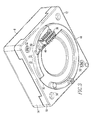
- FIG. 2 is an isometric view of a rotating display device including a display in accordance with an embodiment of the invention
- FIG. 3 is an isometric view of the connector side of the rotating display device of FIG. 2;
- FIGS. 4A and 4B are isometric views of one embodiment of the retention member of FIG. 3;
- FIG. 5 is an exploded isometric view of the rotating display device of FIG. 2;
- FIG. 6 is an isometric view of the second half of the rotating display device of FIG. 2.
- the invention is described in association with a display device for a low voltage circuit breaker, although the invention is applicable to a wide range of electrical apparatus, such as, for example, electrical switching apparatus.
- the phrase "slideably receives" or variations thereof shall mean that a part is adapted to receive another part which slides into it.
- number means one or an integer greater than one ( i.e., a plurality).
- wiring harness or variations thereof shall mean a number ports or connectors that are electrically connected by a number of conductors.
- lip or variations thereof shall mean a projecting edge.
- groove or variations thereof shall mean a channel or depression.
- mechanical fastener or variations thereof shall refer to any suitable fastening, connecting or tightening mechanism including, but not limited to, screws, bolts, and the combination of bolts and nuts.
- variable viewing orientation shall refer to the ability of the display for a rotating display device to be rotated, for example, to a variety of viewing orientations, in order to permit a user to accurately view and interpret the value displayed thereon even when the connector of the electrical apparatus to which it is coupled is disposed in a different or non-standard orientation.
- FIG. 2 depicts a rotating display device 6 that receives and displays a value (e.g., without limitation, operational parameter; setpoint; served value) of an electrical apparatus.
- the rotating display device 6 is mechanically coupled and electrically connected to the electrical apparatus by the connector 4 (FIG. 1) that is located on the electrical apparatus.
- the rotating display device 6 includes a housing 8 having a first side 10 and a second side 12.
- the rotating display device 6 further includes a first half 14 and a second half 16.
- Located on the first side 10 of the housing 8 is a first aperture 18 in which a display 20 is disposed.
- the display 20 displays (outputs) the value that is received from the electrical apparatus.
- the display 20 displays the value in a digital format. However, this is not meant to be limiting since any suitable alternative display format including, but not limited to, an analog display may also be employed.
- the first side 10 of the housing 8 further includes a first control button 22 and a second control button 24.
- the first control button 22 extends through a second aperture 26 while the second control button 24 extends through a third aperture 28.
- the control buttons 22,24 are an optional feature designed to permit the user to control the display 20.
- the control buttons 22,24 may permit the user to switch the value being displayed (e.g. current; voltage) or to change the units in which the value is displayed (e.g., amps; milliamps).
- the housing 8 may also include a Light Emitting Diode (LED) 30 that indicates, for example, whether the rotating display device 6 is electrically connected to the electrical apparatus.
- LED Light Emitting Diode
- the LED 30 is positioned within a fourth aperture 31 that is located on the first side 10 of the housing 8.
- the display 20, control buttons 22,24, and LED 30 are disposed and electrically connected to a printed circuit board 32 (shown in FIG. 5) that is located between the first and second housing halves 14,16.
- the printed circuit board 32 is electrically connected to the electrical apparatus by a wiring harness 34 (shown in FIG. 5) having first and second connectors 36,38 (shown in FIG. 5) that are electrically connected by a number of conductors 40 (shown in FIG. 5).
- the printed circuit board 32 is mechanically coupled and electrically connected to the second connector 38 of the wiring harness 34.
- the second side 12 of the housing 8 includes an aperture 42 in which a rotating member 44 is disposed.
- the rotating member 44 has an aperture 46 that is structured to receive the first connector 36 of the wiring harness 34.
- the first connector 36 extends from the second side 12 of the housing 8 when the first connector 36 is positioned within the aperture 46 of the rotating member 44.
- the first connector 36 is structured to be mechanically coupled and electrically connected to the connector 4 (FIG. 1) that is located on the electrical apparatus thereby electrically connecting the printed circuit board 32 to the electrical apparatus.
- the second side 12 of the housing 8 further includes a number of apertures 50 that are structured to receive mechanical fasteners 52 which secure the second housing half 16 to the first housing half 14.
- a retention member 54 (see FIGS. 4A, 4B, 5, and 6) is structured to be slideably received into the rotating member 44.
- the retention member 54 not only acts as a strain relief and a guide for the conductors 40 of the wiring harness 34, but also secures the first connector 36 to the rotating member 44.
- the retention member 54 includes a first flange 56 and a second flange 58.
- Each of the first and second flanges 56,58 has corresponding first, second, and third surfaces 60,62,64, as best shown with the first flange 56.
- Extending from the first surface 60 of the first flange 56 to the first surface 60 of the second flange is a first web 66.
- the first web 66 includes an aperture 68 that is located, for example, at about the center of the first web 66.
- Extending from the second surface 62 of the first flange 56 to the second surface 62 of the second flange 58 is a second web 70.
- the first web 66 is connected to the second web's inner surface 71.
- the second web 70 is substantially arcuate in shape and includes a substantially arcuate lip 72.
- the first web 66 extends from the first flange 56 to the second flange 58 in a direction substantially perpendicular to an axis 82 (FIG. 5) of the rotating member 44 (see FIG. 5).
- Each of the first and second flanges 56,58 also includes a protrusion 74 extending therefrom. It should be noted, however, that despite FIGS.
- protrusions 74 are structured to securely couple the retention member 54 to the rotating member 44 when the retention member 54 is slideably received into the rotating member 44.
- the printed circuit board 32, the wiring harness 34, and the rotating member 44 are all disposed between the first and second halves 14,16 of the housing 8.
- the display 20 is inserted through the first aperture 18 that is located on the first side 10 of the housing 8 while the first control button 22 and the second control button 24 as well as the LED 30 are inserted through the respective second, third, and fourth apertures 26,28,31, which are also located on the first housing side 10.
- the circuitry (not shown) of the printed circuit board 32 receives the value from a connector 76 that is located on the surface of the printed circuit board 32 that is adjacent to the rotating member 44.
- the connector 76 is mechanically coupled and electrically connected to the second connector 38 of the wiring harness 34 which, as stated above, is electrically connected to the first connector 36.
- the first connector 36 of the wiring harness 34 is structured to be received into the aperture 46 that is located on the rotating member 44.
- the first connector 36 of the wiring harness 34 is secured to the rotating member 44 by the retention member 54 that is slideably received into the rotating member 44.
- the first and second flanges 56,58 of the retention member 54 are structured to be slideably received into a first groove 78 and a second groove 80 that are located on the rotating member 44, respectively.
- the first and second grooves 78,80 extend in a direction substantially perpendicular to an axis 82 of the rotating member 44.
- each of the first and second flanges 56,58 of the retention member 54 includes a number of protrusions 74 that secure the retention member 54 to the rotating member 44.
- the combination of the rotating member 44, the retention member 54 and the first connector 36 of the wiring harness 34, is received into the aperture 42 that is located on the second half 16 of the housing 8.
- the second housing half 16 is secured to the first housing half 14 by a number of mechanical fasteners 52 (see FIG. 3) that are inserted through the apertures 50 that are located on the second side 12 of the housing 8.
- the printed circuit board 32 is secured between the first and second housing halves 14,16 by the mechanical fasteners 52 (FIG. 3).
- FIG. 6 shows the second housing half 16 having disposed therein the rotating member 44.
- the rotating member 44 includes the first connector 36 of the wiring harness 34 which is secured to the rotating member 44 by the retention member 54.
- the rotating member 44 has a lip 84 (as best shown in FIG. 5) that extends along a portion of the perimeter of the rotating member 44.
- the lip 72 of the second web 70 of the retention member 54 in addition to the lip 84 of the rotating member 44 form a complete lip 86 that extends along substantially the entire perimeter of the rotating member 44.
- the complete lip 86 has a first surface 88 (see FIG. 5) that is positioned adjacent to an edge 90 (see FIG. 5) of the rotating member 44 which secures the rotating member 44 to the second housing half 16 when the second housing half and the printed circuit board 32 are secured to the first housing half 14.
Landscapes
- Devices For Indicating Variable Information By Combining Individual Elements (AREA)
- Insertion, Bundling And Securing Of Wires For Electric Apparatuses (AREA)
Abstract
Description
- The invention relates generally to an electrical apparatus and, more particularly, to a display device for receiving and displaying a value from an electrical apparatus. The invention also relates to a retention member that secures a wiring harness that is disposed within a display device.
- Displaying operating parameters (e.g., without limitation, voltage; electrical current; frequency) provides one way for a user to ensure that an electrical apparatus is operating properly. Accordingly, electrical apparatus including, for example, electrical switching apparatus, such as circuit switching devices and circuit interrupters (e.g., without limitation, circuit breakers, contactors, motor starters, motor controllers and other load controllers), often include a connector for outputting a value. The value outputted on the connector is typically indicative of one or more operating parameters. Circuit breakers, such as the low voltage circuit breaker 2, shown in FIG. 1, exemplify one type of electrical apparatus that may include such a connector 4.
- However, electrical apparatus, including circuit breakers, are often mounted or disposed in a wide variety of orientations with the position of the display device display being dictated by such orientation and the corresponding orientation of the connector on the electrical apparatus. The varying orientations of the electrical apparatus make it difficult to read the value displayed on the display when the electrical apparatus is disposed in any orientation other than a vertical one. For example, circuit breakers can often be mounted sideways or in an inverted orientation, thereby requiring the display device's display to be oriented in a corresponding sideways or inverted orientation. This results in the displayed value being displayed in an improper orientation, thereby making it difficult to be accurately read or interpreted by a user.
- These needs and others are met by embodiments of the invention, which provide a rotating display device for viewing a value in a variable viewing orientation.
- In accordance with one aspect of the invention, a retention member is for use with a rotating display device. The rotating display device includes a rotating member disposed therein. The rotating member has a first groove and a second groove that are structured to slideably receive the retention member. The retention member includes: a first flange and a second flange, each of the first and second flanges has a first surface and a second surface, the first flange being structured to be slideably received into the first groove and the second flange being structured to be slideably received into the second groove; and a first web and a second web, the first web extends from the first surface of the first flange to the first surface of the second flange, the second web extends from the second surface of the first flange to the second surface of the second flange.
- In accordance with another aspect of the invention, a rotating display device includes: a housing having a first half and a second half; a display for displaying the value, the display being disposed within the first half; a rotating member disposed within the second half; a retention member slideably received into the rotating member; and a wiring harness secured to the rotating member by the retention member.
- In accordance with another aspect of the invention, an electrical apparatus includes: an enclosure having a surface; a port disposed on the surface of the enclosure, the port being structured to output a value; and a rotating display device coupled to the port. The rotating display device is structured to receive the value and display the value in a variable viewing orientation, the rotating display device includes: a housing having a first half and a second half; a display structured to display the value, the display being disposed within the first half; a rotating member disposed within the second half; a retention member, the retention member is slideably received into the rotating member; and a wiring harness secured to the rotating member by the retention member.
- A full understanding of the invention can be gained from the following description of the preferred embodiments when read in conjunction with the accompanying drawings in which:
- FIG. 1 is a top plan view of a low voltage circuit breaker;
- FIG. 2 is an isometric view of a rotating display device including a display in accordance with an embodiment of the invention;
- FIG. 3 is an isometric view of the connector side of the rotating display device of FIG. 2;
- FIGS. 4A and 4B are isometric views of one embodiment of the retention member of FIG. 3;
- FIG. 5 is an exploded isometric view of the rotating display device of FIG. 2; and
- FIG. 6 is an isometric view of the second half of the rotating display device of FIG. 2.
- The invention is described in association with a display device for a low voltage circuit breaker, although the invention is applicable to a wide range of electrical apparatus, such as, for example, electrical switching apparatus.
- Directional phrases used herein, such as, for example, upper, lower, left, right, vertical, horizontal, top, bottom, above, beneath, clockwise, counterclockwise and derivatives thereof, relate to the orientation of the elements shown in the drawings and are not limiting upon the claims unless expressly recited therein.
- As employed herein, the phrase "slideably receives" or variations thereof shall mean that a part is adapted to receive another part which slides into it.
- As employed herein, the statement that two or more parts are "coupled" together means that the parts are joined together either directly or joined through one or more intermediate parts.
- As employed herein, the term "number" means one or an integer greater than one (i.e., a plurality).
- As employed herein, the term "wiring harness" or variations thereof shall mean a number ports or connectors that are electrically connected by a number of conductors.
- As employed herein, the term "lip" or variations thereof shall mean a projecting edge.
- As employed herein, the term "groove" or variations thereof shall mean a channel or depression.
- As employed herein, the term "mechanical fastener" or variations thereof shall refer to any suitable fastening, connecting or tightening mechanism including, but not limited to, screws, bolts, and the combination of bolts and nuts.
- As employed herein, the term "variable viewing orientation" shall refer to the ability of the display for a rotating display device to be rotated, for example, to a variety of viewing orientations, in order to permit a user to accurately view and interpret the value displayed thereon even when the connector of the electrical apparatus to which it is coupled is disposed in a different or non-standard orientation.
- FIG. 2 depicts a rotating
display device 6 that receives and displays a value (e.g., without limitation, operational parameter; setpoint; served value) of an electrical apparatus. As will be discussed in further detail below, the rotatingdisplay device 6 is mechanically coupled and electrically connected to the electrical apparatus by the connector 4 (FIG. 1) that is located on the electrical apparatus. The rotatingdisplay device 6 includes ahousing 8 having afirst side 10 and asecond side 12. The rotatingdisplay device 6 further includes afirst half 14 and asecond half 16. Located on thefirst side 10 of thehousing 8 is afirst aperture 18 in which adisplay 20 is disposed. Thedisplay 20 displays (outputs) the value that is received from the electrical apparatus. In one embodiment, thedisplay 20 displays the value in a digital format. However, this is not meant to be limiting since any suitable alternative display format including, but not limited to, an analog display may also be employed. - As can be seen from FIG. 2, the
first side 10 of thehousing 8 further includes afirst control button 22 and asecond control button 24. Thefirst control button 22 extends through asecond aperture 26 while thesecond control button 24 extends through athird aperture 28. Thecontrol buttons display 20. For example, thecontrol buttons housing 8 may also include a Light Emitting Diode (LED) 30 that indicates, for example, whether the rotatingdisplay device 6 is electrically connected to the electrical apparatus. TheLED 30 is positioned within a fourth aperture 31 that is located on thefirst side 10 of thehousing 8. Thedisplay 20,control buttons LED 30 are disposed and electrically connected to a printed circuit board 32 (shown in FIG. 5) that is located between the first andsecond housing halves circuit board 32 is electrically connected to the electrical apparatus by a wiring harness 34 (shown in FIG. 5) having first andsecond connectors 36,38 (shown in FIG. 5) that are electrically connected by a number of conductors 40 (shown in FIG. 5). Specifically, the printedcircuit board 32 is mechanically coupled and electrically connected to thesecond connector 38 of thewiring harness 34. - Referring to FIG. 3, the
second side 12 of thehousing 8 includes anaperture 42 in which a rotatingmember 44 is disposed. The rotatingmember 44 has anaperture 46 that is structured to receive thefirst connector 36 of thewiring harness 34. As shown, thefirst connector 36 extends from thesecond side 12 of thehousing 8 when thefirst connector 36 is positioned within theaperture 46 of the rotatingmember 44. Thefirst connector 36 is structured to be mechanically coupled and electrically connected to the connector 4 (FIG. 1) that is located on the electrical apparatus thereby electrically connecting the printedcircuit board 32 to the electrical apparatus. Thesecond side 12 of thehousing 8 further includes a number ofapertures 50 that are structured to receivemechanical fasteners 52 which secure thesecond housing half 16 to thefirst housing half 14. - Referring to FIG. 5, in order to ensure that the
conductors 40 of thewiring harness 34 do not interfere with the various internal components of the rotatingdisplay device 6 and that thefirst connector 36 does not dislodged from the rotatingmember 44 when the rotatingdisplay device 6 is coupled to the electrical apparatus, a retention member 54 (see FIGS. 4A, 4B, 5, and 6) is structured to be slideably received into the rotatingmember 44. Theretention member 54 not only acts as a strain relief and a guide for theconductors 40 of thewiring harness 34, but also secures thefirst connector 36 to the rotatingmember 44. - As can be seen from FIGS. 4A and 4B, the
retention member 54 includes afirst flange 56 and asecond flange 58. Each of the first andsecond flanges third surfaces first flange 56. Extending from thefirst surface 60 of thefirst flange 56 to thefirst surface 60 of the second flange is afirst web 66. Thefirst web 66 includes anaperture 68 that is located, for example, at about the center of thefirst web 66. Extending from thesecond surface 62 of thefirst flange 56 to thesecond surface 62 of thesecond flange 58 is asecond web 70. Thefirst web 66 is connected to the second web'sinner surface 71. In the example embodiment depicted in FIGS. 4A and 4B, thesecond web 70 is substantially arcuate in shape and includes a substantiallyarcuate lip 72. Thefirst web 66 extends from thefirst flange 56 to thesecond flange 58 in a direction substantially perpendicular to an axis 82 (FIG. 5) of the rotating member 44 (see FIG. 5). Each of the first andsecond flanges protrusion 74 extending therefrom. It should be noted, however, that despite FIGS. 4A and 4B showing only oneprotrusion 74 extending from each of the first andsecond flanges second flange more protrusions 74 extending therefrom falls within the scope of this invention. Theprotrusions 74 are structured to securely couple theretention member 54 to the rotatingmember 44 when theretention member 54 is slideably received into the rotatingmember 44. - As can be seen from FIG. 5, the printed
circuit board 32, thewiring harness 34, and the rotatingmember 44 are all disposed between the first andsecond halves housing 8. Thedisplay 20 is inserted through thefirst aperture 18 that is located on thefirst side 10 of thehousing 8 while thefirst control button 22 and thesecond control button 24 as well as theLED 30 are inserted through the respective second, third, andfourth apertures first housing side 10. As employed, the circuitry (not shown) of the printedcircuit board 32 receives the value from aconnector 76 that is located on the surface of the printedcircuit board 32 that is adjacent to the rotatingmember 44. Theconnector 76 is mechanically coupled and electrically connected to thesecond connector 38 of thewiring harness 34 which, as stated above, is electrically connected to thefirst connector 36. - Continuing to refer to FIG. 5, the
first connector 36 of thewiring harness 34 is structured to be received into theaperture 46 that is located on the rotatingmember 44. When positioned within theaperture 46 of the rotatingmember 44, thefirst connector 36 of thewiring harness 34 is secured to the rotatingmember 44 by theretention member 54 that is slideably received into the rotatingmember 44. Specifically, the first andsecond flanges retention member 54 are structured to be slideably received into afirst groove 78 and asecond groove 80 that are located on the rotatingmember 44, respectively. The first andsecond grooves axis 82 of the rotatingmember 44. As stated above, each of the first andsecond flanges retention member 54 includes a number ofprotrusions 74 that secure theretention member 54 to the rotatingmember 44. The combination of the rotatingmember 44, theretention member 54 and thefirst connector 36 of thewiring harness 34, is received into theaperture 42 that is located on thesecond half 16 of thehousing 8. Thesecond housing half 16 is secured to thefirst housing half 14 by a number of mechanical fasteners 52 (see FIG. 3) that are inserted through theapertures 50 that are located on thesecond side 12 of thehousing 8. As can be seen from FIG. 5, the printedcircuit board 32 is secured between the first andsecond housing halves circuit board 32 to the first andsecond housing halves display 20 rotates with thehousing 8 thereby permitting a user to view thedisplay 20 in a variety of viewing orientations. - FIG. 6 shows the
second housing half 16 having disposed therein the rotatingmember 44. As can be seen, the rotatingmember 44 includes thefirst connector 36 of thewiring harness 34 which is secured to the rotatingmember 44 by theretention member 54. The rotatingmember 44 has a lip 84 (as best shown in FIG. 5) that extends along a portion of the perimeter of the rotatingmember 44. When theretention member 54 is secured to the rotatingmember 44, thelip 72 of thesecond web 70 of theretention member 54 in addition to thelip 84 of the rotatingmember 44 form acomplete lip 86 that extends along substantially the entire perimeter of the rotatingmember 44. Thecomplete lip 86 has a first surface 88 (see FIG. 5) that is positioned adjacent to an edge 90 (see FIG. 5) of the rotatingmember 44 which secures the rotatingmember 44 to thesecond housing half 16 when the second housing half and the printedcircuit board 32 are secured to thefirst housing half 14. - While specific embodiments of the invention have been described in detail, it will be appreciated by those skilled in the art that various modifications and alternatives to those details could be developed in light of the overall teachings of the disclosure. Accordingly, the particular arrangements disclosed are meant to be illustrative only and not limiting as to the scope of the invention which is to be given the full breadth of the claims appended and any and all equivalents thereof.
Claims (20)
- A retention member (54) for use with a rotating display device (6), said rotating display device (6) having a rotating member (44) disposed therein, said rotating member (44) having a first groove (78) and a second groove (80) that are structured to slideably receive said retention member (54), said retention member (54) comprising:a first flange (56) and a second flange (58), each of said first and second flanges (56, 58) has a first surface (60) and a second surface (62), said first flange (56) being structured to be slideably received into said first groove (78) and said second flange (58) being structured to be slideably received into said second groove (80); anda first web (66) and a second web (70), said first web (66) extends from said first surface (60) of said first flange (56) to said first surface (60) of said second flange (58), said second web (70) extends from said second surface (62) of said first flange (56) to said second surface (62) of said second flange (58).
- The retention member (54) according to claim 1, wherein each of said first and second flanges (56, 58) has a number of protrusions (74) extending therefrom, said protrusions (74) being structured to secure said retention member (54) to said rotating member (44).
- The retention member (54) according to claim 1, wherein said second web (70) is substantially arcuate.
- The retention member (54) according to claim 3, wherein said second web (70) further comprises an inner surface (71) and said first web (66) is connected to said inner surface (71).
- A rotating display device (6) for displaying a value in a variable viewing orientation, said rotating display device (6) comprising:a housing (8) having a first half and a second half (14, 16);a display (20) for displaying said value, said display (20) being disposed within said first half (14);a rotating member (44) disposed within said second half (16);a retention member (54) slideably received into said rotating member (44); anda wiring harness (34) secured to said rotating member (44) by said retention member (54).
- The rotating display device (6) according to claim 5, wherein said wiring harness (34) comprises a first connector (36) and a second connector (38) that are electrically connected by a number of conductors (40).
- The rotating display device (6) according to claim 6, wherein said first connector (36) of said wiring harness (34) is structured to engage a port (4) disposed on a surface of an electrical apparatus, said port (4) outputting said value; and wherein said second connector (38) of said wiring harness (34) is structured to engage and communicate said value to said display (20).
- The rotating display device (6) according to claim 6, wherein said first half (14) of said housing (8) has an aperture (18) that receives said display (20); wherein said display (20) is mechanically coupled and electrically connected to a printed circuit board (32) which is disposed between said first half (14) and said second half (16) of said housing (8); and wherein said printed circuit board (32) is electrically connected to said second connector (38).
- The rotating display device (6) according to claim 6, wherein said rotating member (44) comprises a first groove (78) and a second groove (80); and wherein said retention member (44) comprises a first flange (56) and a second flange (58), each of said first and second flanges (56, 58) has a first surface (60) and a second surface (62), said first flange (56) being slideably received into said first groove (78) and said second flange (58) being slideably received into said second groove (80), and a first web (66) and a second web (70), said first web (66) extends from said first surface (60) of said first flange (56) to said first surface (60) of said second flange (58), said second web (70) extends from said second surface (62) of said first flange (56) to said second surface (62) of said second flange (58).
- The rotating display device (6) according to claim 9, wherein each of said first and second flanges (56, 58) has a number of protrusions (74) extending therefrom, said protrusions (74) securing said retention member (54) to said rotating member (44).
- The rotating display device (6) according to claim 9, wherein said rotating member (44) has an axis (82); and wherein said first web (66) extends from said first flange (56) to said second flange (58) in a direction substantially perpendicular to said axis (82) of said rotating member (44).
- The rotating display device (6) according to claim 9, wherein said rotating member (44) has an aperture (42) that receives said first connector (36) of said wiring harness (34).
- The rotating display device (6) according to claim 12, wherein each of said first and second flanges (56, 58) has a third surface (64); and wherein said first connector (36) of said wiring harness (34) is positioned within said aperture (42) and substantially adjacent to said third surface (64) of each of said first and second flanges (56, 58).
- An electrical apparatus comprising:an enclosure including a surface;a port (4) disposed on said surface of said enclosure, said port being structured to output a value; anda rotating display device (6) coupled to said port (4), said rotating display device (6) structured to receive said value and display said value in a variable viewing orientation, said rotating display device (6) comprising:a housing (8) having a first half (14) and a second half (16);a display (20) structured to display said value, said display (20) being disposed within said first half (14);a rotating member (44) disposed within said second half (16);a retention member (54), said retention member (54) is slideably received into said rotating member (44); anda wiring harness (34) secured to said rotating member (44) by said retention member (54).
- The electrical apparatus according to claim 14, wherein said wiring harness (34) comprises a first connector (36) and a second connector (38) that are electrically connected by a number of conductors (40).
- The electrical apparatus according to claim 15, wherein said first connector (36) of said wiring harness (34) engages said port (4) disposed on said surface of said enclosure; and wherein said second connector (38) of said wiring harness (34) engages and communicates with said display (20).
- The electrical apparatus according to claim 15, wherein said rotating member (44) further comprises a first groove (78) and a second groove (80); and wherein said retention member (54) comprises a first flange (56) and a second flange (58), each of said first and second flanges (56, 58) has a first surface (60) and a second surface (62), said first flange (56) slideably received into said first groove (78) and said second flange (58) slideably received into said second groove (78), and a first web (66) and a second web (70), said first web (66) extends from said first surface (60) of said first flange (56) to said first surface (60) of said second flange (58), said second web (70) extends from said second surface (62) of said first flange (56) to said second surface (62) of said second flange (58).
- The electrical apparatus according to claim 17, wherein said rotating member (44) has an aperture (46) that receives said first connector (36) of said wiring harness (34).
- The electrical apparatus according to claim 18, wherein each of said first and second flanges (56, 58) has a third surface (64); and wherein said first connector (36) of said wiring harness (34) is positioned within said aperture (46) and substantially adjacent to said third surface (64) of each of said first and second flanges (56, 58).
- The electrical apparatus according to claim 17, wherein each of said first and second flanges (56, 58) has a number of protrusions (74) extending therefrom, said protrusions (74) securing said retention member (54) to said rotating member (44).
Applications Claiming Priority (1)
| Application Number | Priority Date | Filing Date | Title |
|---|---|---|---|
| US11/430,456 US7544063B2 (en) | 2006-05-09 | 2006-05-09 | Rotating display device having wiring harness retention member |
Publications (1)
| Publication Number | Publication Date |
|---|---|
| EP1855302A1 true EP1855302A1 (en) | 2007-11-14 |
Family
ID=38457569
Family Applications (1)
| Application Number | Title | Priority Date | Filing Date |
|---|---|---|---|
| EP07009327A Withdrawn EP1855302A1 (en) | 2006-05-09 | 2007-05-09 | Rotating display device having wiring harness retention member |
Country Status (4)
| Country | Link |
|---|---|
| US (1) | US7544063B2 (en) |
| EP (1) | EP1855302A1 (en) |
| CN (1) | CN101072479B (en) |
| CA (1) | CA2587851A1 (en) |
Families Citing this family (4)
| Publication number | Priority date | Publication date | Assignee | Title |
|---|---|---|---|---|
| TWI370595B (en) * | 2009-02-13 | 2012-08-11 | Primax Electronics Ltd | Rotatable receptacle |
| US9579806B2 (en) | 2012-08-23 | 2017-02-28 | Rethink Robotics, Inc. | Robotic power and signal distribution using laminated cable with separator webs |
| DE102013019562A1 (en) * | 2013-11-22 | 2015-05-28 | Valeo Schalter Und Sensoren Gmbh | Device for transmitting electrical signals to and / or from a rotatable component of a motor vehicle, steering column module and motor vehicle |
| US9530595B2 (en) * | 2013-11-22 | 2016-12-27 | Eaton Corporation | Circuit breaker with low-clearance connections |
Citations (4)
| Publication number | Priority date | Publication date | Assignee | Title |
|---|---|---|---|---|
| US20040225471A1 (en) * | 2003-02-03 | 2004-11-11 | Tate Ronald C. | Utility meter housing arrangement |
| US20050124178A1 (en) * | 2003-12-08 | 2005-06-09 | Lear Corporation | Dockable connection assembly |
| EP1600993A1 (en) | 2004-05-24 | 2005-11-30 | Eaton Corporation | Rotating display device and electrical apparatus employing the same |
| JP2006026203A (en) * | 2004-07-20 | 2006-02-02 | Sophia Co Ltd | Game machine |
Family Cites Families (7)
| Publication number | Priority date | Publication date | Assignee | Title |
|---|---|---|---|---|
| CA1174278A (en) * | 1982-09-16 | 1984-09-11 | Aurele Blain | Clamp-on ammeter |
| FR2562673B1 (en) * | 1984-04-09 | 1987-02-20 | Merlin Gerin | CURRENT MEASUREMENT DEVICE IN AN ELECTRICAL DISTRIBUTION BOARD OR BOX |
| US4731030A (en) * | 1987-01-09 | 1988-03-15 | Unisys Corporation | Tilt and swivel assembly for terminal monitor |
| JP4716541B2 (en) * | 2000-04-14 | 2011-07-06 | ナイルス株式会社 | Rotating connector device |
| US6488510B2 (en) * | 2001-03-21 | 2002-12-03 | Long-Beam Enterprise Co., Ltd. | Rotary-plug wall lamp |
| JP2002311845A (en) * | 2001-04-16 | 2002-10-25 | Fujitsu Ltd | Display device |
| TWI255978B (en) * | 2003-03-28 | 2006-06-01 | Quanta Comp Inc | Electronic device and its combination structure with rotation buckle and signal transmission |
-
2006
- 2006-05-09 US US11/430,456 patent/US7544063B2/en not_active Expired - Fee Related
-
2007
- 2007-05-08 CA CA002587851A patent/CA2587851A1/en not_active Abandoned
- 2007-05-09 CN CN200710126613XA patent/CN101072479B/en active Active
- 2007-05-09 EP EP07009327A patent/EP1855302A1/en not_active Withdrawn
Patent Citations (4)
| Publication number | Priority date | Publication date | Assignee | Title |
|---|---|---|---|---|
| US20040225471A1 (en) * | 2003-02-03 | 2004-11-11 | Tate Ronald C. | Utility meter housing arrangement |
| US20050124178A1 (en) * | 2003-12-08 | 2005-06-09 | Lear Corporation | Dockable connection assembly |
| EP1600993A1 (en) | 2004-05-24 | 2005-11-30 | Eaton Corporation | Rotating display device and electrical apparatus employing the same |
| JP2006026203A (en) * | 2004-07-20 | 2006-02-02 | Sophia Co Ltd | Game machine |
Also Published As
| Publication number | Publication date |
|---|---|
| US7544063B2 (en) | 2009-06-09 |
| CN101072479A (en) | 2007-11-14 |
| CN101072479B (en) | 2011-07-27 |
| US20080047179A1 (en) | 2008-02-28 |
| CA2587851A1 (en) | 2007-11-09 |
Similar Documents
| Publication | Publication Date | Title |
|---|---|---|
| US8693170B2 (en) | Control assembly comprising a variable speed drive and a circuit breaker | |
| US6496378B2 (en) | Housing suitable for interconnection to a junction box and a duplex housing | |
| US7095302B2 (en) | Rotating display device and electrical apparatus employing the same | |
| US7695313B2 (en) | Electrical enclosure, and panel assembly and mounting assembly therefor | |
| US6064289A (en) | Electromagnetic contactor with overload relay | |
| US5027091A (en) | Molded case circuit interrupter rating plug keying and interlock arrangement | |
| JPH02230629A (en) | Auxiliary switching element of circuit breaker | |
| EP1596471A1 (en) | Terminal arrangement of electrical apparatus | |
| US6504695B1 (en) | Combination current sensor and relay | |
| KR20080059503A (en) | Earth leakage breaker | |
| IE950037A1 (en) | A circuit breaker | |
| US7646271B2 (en) | Electrical switching apparatus and interlocking phase barrier therefor | |
| CA2587851A1 (en) | Rotating display device having wiring harness retention member | |
| EP3259769B1 (en) | Electrical switching apparatus, and interface assembly and display apparatus therefor | |
| US4989118A (en) | Off-set terminal configuration for electrically coupling the load side of adjacent circuit breakers | |
| US4680672A (en) | Molded case circuit breaker with front accessible control panel | |
| US20080084655A1 (en) | Electrical enclosure and interior assembly therefor | |
| US6064018A (en) | Molded case circuit breaker molded pole assembly | |
| EP0573254B1 (en) | Housing for control unit | |
| US20060209499A1 (en) | Horizontally mounted power circuit breaker bus assembly | |
| US12476064B2 (en) | Ground fault circuit interrupter incorporating circuit breaker, shunt module and ground fault detection device | |
| JP2001167682A (en) | Multipole switch terminal unit | |
| JP7233355B2 (en) | Mounting terminal block for circuit breaker | |
| JP2005071811A (en) | Circuit breaker | |
| JP2002025412A (en) | Circuit breaker for wiring |
Legal Events
| Date | Code | Title | Description |
|---|---|---|---|
| PUAI | Public reference made under article 153(3) epc to a published international application that has entered the european phase |
Free format text: ORIGINAL CODE: 0009012 |
|
| AK | Designated contracting states |
Kind code of ref document: A1 Designated state(s): AT BE BG CH CY CZ DE DK EE ES FI FR GB GR HU IE IS IT LI LT LU LV MC MT NL PL PT RO SE SI SK TR |
|
| AX | Request for extension of the european patent |
Extension state: AL BA HR MK YU |
|
| 17P | Request for examination filed |
Effective date: 20080513 |
|
| AKX | Designation fees paid |
Designated state(s): FR GB IT NL |
|
| 17Q | First examination report despatched |
Effective date: 20080627 |
|
| REG | Reference to a national code |
Ref country code: DE Ref legal event code: 8566 |
|
| STAA | Information on the status of an ep patent application or granted ep patent |
Free format text: STATUS: THE APPLICATION IS DEEMED TO BE WITHDRAWN |
|
| 18D | Application deemed to be withdrawn |
Effective date: 20091201 |