EP1855134A2 - A cable assembly as well as a method for installing such a cable assembly - Google Patents
A cable assembly as well as a method for installing such a cable assembly Download PDFInfo
- Publication number
- EP1855134A2 EP1855134A2 EP07009425A EP07009425A EP1855134A2 EP 1855134 A2 EP1855134 A2 EP 1855134A2 EP 07009425 A EP07009425 A EP 07009425A EP 07009425 A EP07009425 A EP 07009425A EP 1855134 A2 EP1855134 A2 EP 1855134A2
- Authority
- EP
- European Patent Office
- Prior art keywords
- cable
- cable assembly
- communication
- connecting element
- assembly according
- Prior art date
- Legal status (The legal status is an assumption and is not a legal conclusion. Google has not performed a legal analysis and makes no representation as to the accuracy of the status listed.)
- Granted
Links
Images





Classifications
-
- G—PHYSICS
- G02—OPTICS
- G02B—OPTICAL ELEMENTS, SYSTEMS OR APPARATUS
- G02B6/00—Light guides; Structural details of arrangements comprising light guides and other optical elements, e.g. couplings
- G02B6/46—Processes or apparatus adapted for installing or repairing optical fibres or optical cables
- G02B6/50—Underground or underwater installation; Installation through tubing, conduits or ducts
- G02B6/52—Underground or underwater installation; Installation through tubing, conduits or ducts using fluid, e.g. air
-
- G—PHYSICS
- G02—OPTICS
- G02B—OPTICAL ELEMENTS, SYSTEMS OR APPARATUS
- G02B6/00—Light guides; Structural details of arrangements comprising light guides and other optical elements, e.g. couplings
- G02B6/24—Coupling light guides
- G02B6/36—Mechanical coupling means
- G02B6/38—Mechanical coupling means having fibre to fibre mating means
- G02B6/3807—Dismountable connectors, i.e. comprising plugs
- G02B6/3887—Anchoring optical cables to connector housings, e.g. strain relief features
- G02B6/38875—Protection from bending or twisting
-
- G—PHYSICS
- G02—OPTICS
- G02B—OPTICAL ELEMENTS, SYSTEMS OR APPARATUS
- G02B6/00—Light guides; Structural details of arrangements comprising light guides and other optical elements, e.g. couplings
- G02B6/24—Coupling light guides
- G02B6/36—Mechanical coupling means
- G02B6/38—Mechanical coupling means having fibre to fibre mating means
- G02B6/3807—Dismountable connectors, i.e. comprising plugs
- G02B6/3887—Anchoring optical cables to connector housings, e.g. strain relief features
- G02B6/3888—Protection from over-extension or over-compression
-
- G—PHYSICS
- G02—OPTICS
- G02B—OPTICAL ELEMENTS, SYSTEMS OR APPARATUS
- G02B6/00—Light guides; Structural details of arrangements comprising light guides and other optical elements, e.g. couplings
- G02B6/24—Coupling light guides
- G02B6/36—Mechanical coupling means
- G02B6/38—Mechanical coupling means having fibre to fibre mating means
- G02B6/3807—Dismountable connectors, i.e. comprising plugs
- G02B6/3887—Anchoring optical cables to connector housings, e.g. strain relief features
- G02B6/3889—Anchoring optical cables to connector housings, e.g. strain relief features using encapsulation for protection, e.g. adhesive, molding or casting resin
Definitions
- the invention relates to a cable assembly for communication purposes, comprising
- the network When optical fibre networks are installed, the network comprises several connections for connecting the various end users. Various techniques are used for connecting the optical fibre from the main network to the end user's house.
- the cable assembly consisting of a communication cable provided with a communication connector is passed through the cable guide to the end position as a pre-prepared assembly.
- the connector on the other hand, which is likewise passed through the cable guide, has considerable diameter dimensions in comparison with the communication cable, making it necessary to install comparatively wide cable guides in the ground.
- said cable assembly must be passed through the cable guide from the end position to its end position. This makes it necessary carry out operations at the end position at the end user's location, which is undesirable in view of the extent of planning and the man-hours involved.
- the cable assembly is to that end characterised in that in order to make it possible to pass the communication cable through the cable guide, the optical fibre is exposed at the free, front end of the cable, which end is fixedly surrounded by a connecting element, which can be mechanically connected to the communication connector after the communication cable has been passed through the cable guide.
- the communication connector can be connected in communicative contact to the optical fibre by means of a simple mechanical operation after the cable assembly has been led to the end position, whilst on the other hand no complex and costly finishing operations, such as polishing, need to be carried out at the end user's location.
- the cable assembly is to that end characterised in that a spring element may be provided round the optical fibre between the connecting element and the cable sheath(s). Said spring element may be retained by the connecting element and a retaining sleeve arranged around the optical fibre. In this way any loads exerted on the end faces of an optical fibre end and the connecting element can be absorbed by the compression of the spring element, thus preventing damage to the connecting element and/or the optical fibre.
- the connecting element may be provided with at least one recess in its circumferential surface, which recess may be configured as a circular recess formed in the circumferential surface in a special embodiment.
- the connecting element and the spring element may be protected by a removable protective element to be provided round the free end of the communication cable.
- the communication connector may comprise at least one sleeve to be provided around the connecting element for use in the final assembly of the cable assembly.
- said sleeve may be made up of two or more sleeve elements to be provided around the connecting element.
- the sleeve may be provided with spaced-apart first and second cams extending towards the connecting element, with the first cam engaging in the recess formed in the connecting element and the second cam engaging the spring element.
- the second cam mates with a cam present on the retaining sleeve.
- the length dimension of the recess is according to the invention larger than the length dimension of the first cam, seen in the longitudinal direction of the cable.
- the communication connector comprises a connector housing to be provided round the sleeve to facilitate further assembly operations.
- the connector housing comprises a cam extending towards the sleeve, which cam engages in a recess formed in the outer circumference of the sleeve.
- the maximum diameter of the cable assembly provided with the connecting element lies between 60%-95% of the inner diameter of the cable guide and more in particular the maximum diameter of the cable assembly provided with the connecting element lies between 70%-85% of the inner diameter of the cable guide.
- the maximum diameter of the cable assembly provided with the connecting element is less than 200% the diameter of the communication cable or less than 150% the diameter of the communication cable or less than 120% the diameter of the communication cable.
- the maximum diameter of the cable assembly provided with the connecting element is less than the diameter of the communication cable.
- the length of the connecting element is less than 10 times its maximum diameter or less than 8 times its maximum diameter or less than 6 times its maximum diameter.
- the invention also relates to a device for collecting the front end of a cable assembly for communication purposes, which cable assembly comprises a communication cable having a first free end and which cable is be passed through a cable guide from a starting position to an end position with its front end.
- said device comprises an enclosure to be positioned around said end position of said cable guide, said enclosure being provided with one or more ventilation openings.
- said enclosure is configured as a tube-shaped element having a first and a second open end, wherein said first open end is provided with connecting means for coupling with the end position of said cable guide.
- said second open end is provided with a closure cap, which functions as an end stop for the front end of the cable assembly upon leaving the cable guide.
- said device comprising a collecting chamber accommodating said enclosure, said collecting chamber serving for collecting transfer liquid used for passing said cable assembly through said cable guide.
- the method for installing a cable assembly for communication purposes comprising a communication cable having a first free end and wherein the cable is built up of at least an optical fibre, which is coaxially surrounded by at least one cable sheath, comprises the steps of:
- numeral 1 indicates a first embodiment of the cable assembly for communication purposes according to the invention.
- the cable assembly 1 is built up of a communication cable 6 having a front free end 4, which cable can be passed through a cable guide (not shown) to an end position with its front end 4.
- the communication cable 6 is at least made up of an optical fibre 12, which is coaxially surrounded by at least one cable sheath 6a as well as a strain relieving sheath 10.
- a buffer sheath 8 is furthermore provided round the optical fibre 12.
- the connecting element 16 has a front end face 16a and a back face 16b, which is in contact with the optical fibre 12.
- the front end face 16a is configured as a surface which is centrally provided with a polished glass fibre surface, which can be placed into communication with a similar polished surface of a counter connector (not shown).
- the connecting element 16 is provided with at least one recess 18, which is configured as a circular recess formed in the circumferential surface.
- the function of said recess 18 will be explained in more detail further on in the description of the figures.
- a spring element 14 is arranged round the optical fibre 12 between the connecting element 16 and the cable sheaths 8-10-6a. In the fully assembled condition of the connector, the spring element 14 functions to press the polished glass fibre surfaces together with a sufficient force (not too much force, since mechanical stresses may lead to cracking of the glass material) upon connection with a counter connector so as to effect a physical contact with a minimal optical signal attenuation of the connector connection.
- the connecting element 16 and the spring element 14 form part of a semi-finished communication connector 2.
- the embodiment of the cable assembly that is shown in figure 1 is passed through a cable guide in the direction of an end position from a central distribution point. At the end position, final assembly of the semi-finished communication connector 2 takes place, so that the cable assembly 1 can be used for communication applications.
- FIG 2 This embodiment is shown in figure 2, in which the cable assembly 1 is passed through an underground cable guide 22 (for example a cable conduit).
- an underground cable guide 22 for example a cable conduit.
- a protective element 20 is used in passing the cable assembly through the cable guide 22, which protective element 20 protects the free end 4 of the cable assembly and more in particular the connecting element 16 and the spring element 14.
- the protective element 20 is removable in this embodiment. Once the cable assembly 1 has been passed through the cable guide 22 to the end position (for example an end user's meter cupboard), the protective element 20 must be removed, whereupon the final assembly of the semi-finished communication connector 2 (made up of the connecting element 16 and the spring element 14 at this stage) is to take place.
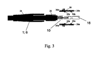
- a kink protector 24 is first slipped over the cable assembly 1. Then a shrink sleeve 26 is fitted round the outer cable sheath 6, after which the connecting element 16 and the spring element 14 are protected by a connector housing.
- the connector sleeve 28 is built up of two sleeve elements 28a-28b, which can be fitted together and over the connecting element 16 and the spring element 14, respectively, by means of a clamped connection or a snap connection.
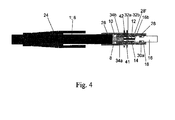
- each housing element 28a-28b is provided with a first inwardly oriented cam 30a-30b, which, upon placement around the connecting element 16, extends into the recess 18 of the connecting element 16.
- the length dimension of the recess 18 is greater than the length dimension of the first cam 30a-30b, seen in the longitudinal direction of the cable 1.
- the sleeve 28, and more in particular the two housing elements 28a- 28b is (are each) provided with a second inwardly oriented cam 32a-32b spaced from the first inwardly oriented cam 30a-30b, which second cam 32a-32b engages the spring element.
- the spring element 14 is thus retained between the second cam 32a-32b and the end face 16b of the connecting element 16.
- This manner of retainment of the spring element 14, in conjunction with the larger dimension of the recess 18 in comparison with the first cam 30a-30b extending into said recess 18, enables a slight degree of compression of the connecting element as a result of the action of the spring element when longitudinal forces are exerted thereon. In this way the optical fibre 12 is not subjected to loads that may affect the fibre adversely.
- the strain relieving sheath/element 10 which may for example be made of aramid fibres formed around the surfaces 34a-34b, is provided with a screw or a knurled edge or other friction-increasing surface.
- the strain relieving sheath 10 is thus clamped onto the surfaces 34a-34b of the two sleeve elements 28a-28b by the shrink sleeve 26.
- the kink protector 24 can be slid in the direction of the communication connector 2, so that it protects the shrink sleeve 26 and comes to abut against a first upwardly oriented cam 42 provided on each housing element 28a-28b.
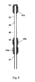
- the free end of the connecting elements 16 projecting from the sleeve 28 is further protected by means of a protective sleeve 36, which is provided with an inwardly oriented cam 36a, which precisely fits in the circular recess 28' formed in the external surface of the sleeve 28.
- the protective sleeve 36 thus comes to abut against a further outwardly oriented cam 41, which forms part of each sleeve element 28a-28b.
- the final assembly of the communication connector 2 is completed by the provision of a connector envelope 37, which can be slid over the protective sleeve 36, the upright cams 41-42 and the kink protector 24.
- Figure 6 discloses yet another embodiment of a cable assembly 1, in which the spring element 14 is not arranged around the optical fibre 12, as in the embodiments that are shown in Figures 1-5, but around an element portion 43a of a coupling element 43 provided around the optical fibre 12 between the connecting element 16 and the cable sheath 6a.
- said intermediate element 43 has a hexagonal outer circumference, around which the sleeve elements 28a-28b (not shown) can be clamped. Because of this surface configuration, sliding or rotating movement is not possible, so that there is no need for a cam-recess configuration.
- the connecting element 16 is protected by a protective element 20, whilst the spring element 14 and the ring 38 are protected by a protective sleeve 20a.
- the ring 38 is disposed between the spring element 14 and the sheaths 6a, 8, 10 and is provided with internal screw thread for being fitted around the sheath 6a.
- the ring 38 functions to hold the protective sleeve 20a in place.
- the protective sleeve 20a and the protective element 20 may be configured as one unit, which may have a slightly larger external diameter, however.
- a ring 38 may be provided between the spring element 14 and the sheaths 6a, 8, 10. After the cable assembly 1 has been moved to the end position and the kink protector 24 and the shrink sleeve 26 have been provided, said ring 38 is pressed down in the connector sleeve 28 (which need not be divisible in this embodiment). As a result, the spring element 14 is biased.
- the ring 38 is provided with an upright, circular edge 14, which fits in a recess 28d formed in the inner circumference of the sleeve elements 28a-28b. This principle is shown in yet another embodiment in Figure 7.
- a semi-finished communication connector can be passed through a cable guide together with the communication cable in an effective manner by exerting a pulling or pushing force, which force may or may not be provided by a gas medium under pressure. In this way no complex assembly operations need to be carried out at the end position.
- Figures 8 and 9 disclose a device (46) for collecting the front end of a cable assembly (1; 6) according to the invention.
- the cable assembly is passed through a cable guide (54), which ends or terminates for example at home of an end user.
- the cable assembly is passed through said cable guide (54) using a transfer medium, for example pressurized air or a liquid, from a starting position to an end position (54a), which is located inside the end user's home.
- a transfer medium for example pressurized air or a liquid
- said device (46) comprises an enclosure (48), which is to be positioned around the end position (54a) of the cable guide 54).
- said enclosure (46) is provided with one or more ventilation openings (50) allowing the passage of said transfer medium (pressurized air or liquid) out of said enclosure when passing the cable assmbly through said cable guide (54).
- said enclosure (46) is configured as a tube-shaped element (48) having a first (48a) and a second open end (48b), wherein said first open end (48a) is provided with connecting means (56) for coupling with the end position (54a) of said cable guide (54).
- the second open end (48b) is provided with a closure cap (52).
- said device (46) comprising a collecting chamber (58), in which said enclosure (48) is accommodated.
- the collecting chamber (58) serves for collecting transfer liquid (60) used for passing said cable assembly (1-6) through said cable guide (54).
- the cable assembly according to the invention has preferred dimensions allowing a proper and unhampered displacement of the cable assembly through the cable guide is possible even passing sharp bends in the cable guide.
- the embodiments of the cable assembly shown in Figures 1-5 are provided with a connector element 16 of 1.25 mm diameter.
- the cable 6 has a 1.8 mm diameter, whereas the protective element 20 is 13 mm long and has a maximum diameter of 2.2 mm.
- the complete cable assembly as shown in Figure 2 can be blown through a cable guide 22 with diameter of 4/3 mm having bends of radius down to 5 cm.
- yet another preferred embodiment consists of a cable 6 of 1.8 mm diameter with connector element and a protective element 20 of 20.5 mm long and a maximum diameter of 2.85 mm.
- This cable assembly can be blown through a 5/3.5 mm cable guide 22.
- the embodiment of Figure 7 has a reduced diameter as it uses two protetective elements, that is element 20 placed over the connector element 16 and protective sleeve 20a placed over the rear assembly.
- the protective sleeve 20b can be made of soft material, e.g. a heat shrinkable plastic tube which can later be removed (cut away) easily.
- the cable 6 has a diameter of 1.8 mm and protective element 20 is 20.5 mm long and has a maximum diameter of 2.65 mm.
- the cable assembly can be blown through a 4/3 mm cable guide 22.
- the embodiment of Figure 8 consists of a cable 6 having a 1.8 mm diameter with a protective element 20 of 18.5 mm long and a maximum diameter of 3.25 mm.
- This embodiment of the cable assembly can be blown through a 5/3.5 mm cable guide, although it is preferable to use a larger cable guide having a diameter of e.g. 7/5.5 mm.
Landscapes
- Physics & Mathematics (AREA)
- General Physics & Mathematics (AREA)
- Optics & Photonics (AREA)
- Mechanical Coupling Of Light Guides (AREA)
Abstract
Description
- The invention relates to a cable assembly for communication purposes, comprising
- a communication cable having a first free end, which cable can be passed through a cable guide from a starting position to an end position with its front end, and
- a communication connector,
- When optical fibre networks are installed, the network comprises several connections for connecting the various end users. Various techniques are used for connecting the optical fibre from the main network to the end user's house.
- One such technique is leading the communication cable through to the end user's location, after which a so-called communication connector is fitted to the free end in situ. This is not an advisable technique, since it is necessary to expose the optical fibre by removing the cable sheath, to mount the exposed optical fibre end in the connector and to polish the end face of the optical fibre so as to enable a good signal transmission.
- In another embodiment, the cable assembly consisting of a communication cable provided with a communication connector is passed through the cable guide to the end position as a pre-prepared assembly. The connector, on the other hand, which is likewise passed through the cable guide, has considerable diameter dimensions in comparison with the communication cable, making it necessary to install comparatively wide cable guides in the ground. In addition to that it is difficult to pass such a cable assembly, with a complete connector mounted to the free front end of the communication cable, through the cable guide. More specifically, said cable assembly must be passed through the cable guide from the end position to its end position. This makes it necessary carry out operations at the end position at the end user's location, which is undesirable in view of the extent of planning and the man-hours involved. It is the object of the invention to obviate the above drawbacks of the existing installation techniques and to provide a cable assembly that does not have these drawbacks. More specifically it is an object of the invention to provide a cable assembly as mentioned in the introduction which makes it possible to lead individual cable assemblies from a central point to the various end users, where the connector can be mounted by means of a simple mounting operation.
- According to the invention, the cable assembly is to that end characterised in that in order to make it possible to pass the communication cable through the cable guide, the optical fibre is exposed at the free, front end of the cable, which end is fixedly surrounded by a connecting element, which can be mechanically connected to the communication connector after the communication cable has been passed through the cable guide.
- Thus, the communication connector can be connected in communicative contact to the optical fibre by means of a simple mechanical operation after the cable assembly has been led to the end position, whilst on the other hand no complex and costly finishing operations, such as polishing, need to be carried out at the end user's location.
- According to a further aspect of the invention, the cable assembly is to that end characterised in that a spring element may be provided round the optical fibre between the connecting element and the cable sheath(s). Said spring element may be retained by the connecting element and a retaining sleeve arranged around the optical fibre. In this way any loads exerted on the end faces of an optical fibre end and the connecting element can be absorbed by the compression of the spring element, thus preventing damage to the connecting element and/or the optical fibre.
- The connecting element may be provided with at least one recess in its circumferential surface, which recess may be configured as a circular recess formed in the circumferential surface in a special embodiment.
- According to the invention, in order to make it easier to pass the cable assembly through the cable guide, the connecting element and the spring element may be protected by a removable protective element to be provided round the free end of the communication cable.
- According to the invention, the communication connector may comprise at least one sleeve to be provided around the connecting element for use in the final assembly of the cable assembly.
- To facilitate the final assembly at the end position, said sleeve may be made up of two or more sleeve elements to be provided around the connecting element.
- More specifically, in a specific embodiment the sleeve may be provided with spaced-apart first and second cams extending towards the connecting element, with the first cam engaging in the recess formed in the connecting element and the second cam engaging the spring element.
- On the one hand a good mechanical connection of the connecting element to the sleeve or sleeve elements is obtained in this way, whilst on the other hand any compression of the connecting element as a result of a force being exerted on the end face thereof can be absorbed by the compression of the spring element.
- More specifically, the second cam mates with a cam present on the retaining sleeve.
- In order to absorb any forces being exerted on the end face of the connecting element through compression of the spring element and movement of the sleeve along therewith, as already explained in the foregoing, the length dimension of the recess is according to the invention larger than the length dimension of the first cam, seen in the longitudinal direction of the cable.
- The communication connector comprises a connector housing to be provided round the sleeve to facilitate further assembly operations.
- According to the invention, in order realise a proper retainment and prevent the connector housing from undesirably becoming detached from the sleeve, the connector housing comprises a cam extending towards the sleeve, which cam engages in a recess formed in the outer circumference of the sleeve.
- Preferably the maximum diameter of the cable assembly provided with the connecting element lies between 60%-95% of the inner diameter of the cable guide and more in particular the maximum diameter of the cable assembly provided with the connecting element lies between 70%-85% of the inner diameter of the cable guide.
- In a further preferred embodiment the maximum diameter of the cable assembly provided with the connecting element is less than 200% the diameter of the communication cable or less than 150% the diameter of the communication cable or less than 120% the diameter of the communication cable.
- However it is preferred that the maximum diameter of the cable assembly provided with the connecting element is less than the diameter of the communication cable.
- Furthermore in yet another embodiments the length of the connecting element is less than 10 times its maximum diameter or less than 8 times its maximum diameter or less than 6 times its maximum diameter.
- With the above constructional dimensions a proper and unhampered displacement of the cable assembly through the cable guide is possible even passing sharp bends in the cable guide.
- The invention also relates to a device for collecting the front end of a cable assembly for communication purposes, which cable assembly comprises a communication cable having a first free end and which cable is be passed through a cable guide from a starting position to an end position with its front end. According to the invention said device comprises an enclosure to be positioned around said end position of said cable guide, said enclosure being provided with one or more ventilation openings.
- This allows a versatile collection of the front end of the cable assembly when being guided through the cable guide with the aid of a transfer medium, such as air or liquid,
- More in particular said enclosure is configured as a tube-shaped element having a first and a second open end, wherein said first open end is provided with connecting means for coupling with the end position of said cable guide. This allows a quick and secure coupling and uncoupling of the device to the cable guide at the premises of the end user, where the cable assembly is to be installed.
- In a further embodiment said second open end is provided with a closure cap, which functions as an end stop for the front end of the cable assembly upon leaving the cable guide.
- In a further improved embodiment said device comprising a collecting chamber accommodating said enclosure, said collecting chamber serving for collecting transfer liquid used for passing said cable assembly through said cable guide.
- According to the invention the method for installing a cable assembly for communication purposes, said cable assembly comprising a communication cable having a first free end and wherein the cable is built up of at least an optical fibre, which is coaxially surrounded by at least one cable sheath, comprises the steps of:
- i) providing a cable guide having a starting point and an end point located at an end users home;
- ii) guiding said cable assembly with the optical fibre being exposed at the free, front end of the cable, which end is fixedly surrounded by a connecting element from said starting point towards said end point using a transfer medium;
- iii) collecting the free, front end of the cable assembly at the end point;
- iv) mechanically connecting the free, front end of the cable assembly to a communication connector.
In a further improvement step iii) comprises further the step of - v) collecting the transfer fluid at the end point during the guiding of the cable assembly through the cable guide according to step ii).
- The invention will now be explained in more detail with reference to a drawing, in which:
- Figure 1 shows a first embodiment of a cable assembly according to the invention;
- Figure 2 shows the cable assembly of figure 1 while being passed through a cable guide;
- Figure 3 shows a first final assembly situation of the cable assembly in the end position;
- Figure 4 shows a second final assembly situation of the cable assembly;
- Figure 5 shows a third final assembly situation of the cable assembly;
- Figures 6 shows another embodiment of a cable assembly according to the invention; and
- Figures 7 shows yet another embodiment of a cable assembly according to the invention.
- For a better understanding of the invention, like parts will be indicated by the same numerals in the following description of the figures of the appended drawings.
- In figure 1,
numeral 1 indicates a first embodiment of the cable assembly for communication purposes according to the invention. Thecable assembly 1 is built up of acommunication cable 6 having a frontfree end 4, which cable can be passed through a cable guide (not shown) to an end position with itsfront end 4. - The
communication cable 6 is at least made up of anoptical fibre 12, which is coaxially surrounded by at least onecable sheath 6a as well as astrain relieving sheath 10. In this embodiment abuffer sheath 8 is furthermore provided round theoptical fibre 12. - To make it easier to pass the
communication cable 6 through the cable guide (not shown), theoptical cable 12 has been exposed at the free,front end 4 of thecable 6, which end is fixedly surrounded by a connectingelement 16. The connectingelement 16 has afront end face 16a and aback face 16b, which is in contact with theoptical fibre 12. Thefront end face 16a is configured as a surface which is centrally provided with a polished glass fibre surface, which can be placed into communication with a similar polished surface of a counter connector (not shown). - The connecting
element 16 is provided with at least onerecess 18, which is configured as a circular recess formed in the circumferential surface. The function of saidrecess 18 will be explained in more detail further on in the description of the figures. As is also shown clearly in figure 1, aspring element 14 is arranged round theoptical fibre 12 between the connectingelement 16 and the cable sheaths 8-10-6a. In the fully assembled condition of the connector, thespring element 14 functions to press the polished glass fibre surfaces together with a sufficient force (not too much force, since mechanical stresses may lead to cracking of the glass material) upon connection with a counter connector so as to effect a physical contact with a minimal optical signal attenuation of the connector connection. - The connecting
element 16 and thespring element 14 form part of asemi-finished communication connector 2. - According to the invention, the embodiment of the cable assembly that is shown in figure 1 is passed through a cable guide in the direction of an end position from a central distribution point. At the end position, final assembly of the
semi-finished communication connector 2 takes place, so that thecable assembly 1 can be used for communication applications. - This embodiment is shown in figure 2, in which the
cable assembly 1 is passed through an underground cable guide 22 (for example a cable conduit). To protect the components of thesemi-finished communication connector 2, in this case the connectingelement 16 and thespring element 14, aprotective element 20 is used in passing the cable assembly through thecable guide 22, whichprotective element 20 protects thefree end 4 of the cable assembly and more in particular the connectingelement 16 and thespring element 14. - The
protective element 20 is removable in this embodiment. Once thecable assembly 1 has been passed through thecable guide 22 to the end position (for example an end user's meter cupboard), theprotective element 20 must be removed, whereupon the final assembly of the semi-finished communication connector 2 (made up of the connectingelement 16 and thespring element 14 at this stage) is to take place. - Upon final assembly and mounting of the
complete communication connector 2, akink protector 24 is first slipped over thecable assembly 1. Then ashrink sleeve 26 is fitted round theouter cable sheath 6, after which the connectingelement 16 and thespring element 14 are protected by a connector housing. In this embodiment shown in figure 3, theconnector sleeve 28 is built up of two sleeve elements 28a-28b, which can be fitted together and over the connectingelement 16 and thespring element 14, respectively, by means of a clamped connection or a snap connection. - As figure 3 and also figure 4 clearly show, each housing element 28a-28b is provided with a first inwardly oriented
cam 30a-30b, which, upon placement around the connectingelement 16, extends into therecess 18 of the connectingelement 16. As is clearly shown in figure 4 as well as in figure 5, the length dimension of therecess 18 is greater than the length dimension of thefirst cam 30a-30b, seen in the longitudinal direction of thecable 1. - Furthermore, the
sleeve 28, and more in particular the two housing elements 28a- 28b, is (are each) provided with a second inwardly orientedcam 32a-32b spaced from the first inwardly orientedcam 30a-30b, whichsecond cam 32a-32b engages the spring element. Thespring element 14 is thus retained between thesecond cam 32a-32b and theend face 16b of the connectingelement 16. This manner of retainment of thespring element 14, in conjunction with the larger dimension of therecess 18 in comparison with thefirst cam 30a-30b extending into saidrecess 18, enables a slight degree of compression of the connecting element as a result of the action of the spring element when longitudinal forces are exerted thereon. In this way theoptical fibre 12 is not subjected to loads that may affect the fibre adversely. - As is clearly shown in Figure 4, the strain relieving sheath/
element 10, which may for example be made of aramid fibres formed around thesurfaces 34a-34b, is provided with a screw or a knurled edge or other friction-increasing surface. Thestrain relieving sheath 10 is thus clamped onto thesurfaces 34a-34b of the two sleeve elements 28a-28b by theshrink sleeve 26. In this way a good strain relieving connection between thecommunication connector 2 and theouter sheath 6a is realised. Thekink protector 24 can be slid in the direction of thecommunication connector 2, so that it protects theshrink sleeve 26 and comes to abut against a first upwardly oriented cam 42 provided on each housing element 28a-28b. - As is clearly shown in Figure 5, the free end of the connecting
elements 16 projecting from thesleeve 28 is further protected by means of aprotective sleeve 36, which is provided with an inwardly orientedcam 36a, which precisely fits in the circular recess 28' formed in the external surface of thesleeve 28. Theprotective sleeve 36 thus comes to abut against a further outwardly orientedcam 41, which forms part of each sleeve element 28a-28b. The final assembly of thecommunication connector 2 is completed by the provision of aconnector envelope 37, which can be slid over theprotective sleeve 36, the upright cams 41-42 and thekink protector 24. - Figure 6 discloses yet another embodiment of a
cable assembly 1, in which thespring element 14 is not arranged around theoptical fibre 12, as in the embodiments that are shown in Figures 1-5, but around anelement portion 43a of acoupling element 43 provided around theoptical fibre 12 between the connectingelement 16 and thecable sheath 6a. As is clearly shown in the cross-sectional view of figure 6, saidintermediate element 43 has a hexagonal outer circumference, around which the sleeve elements 28a-28b (not shown) can be clamped. Because of this surface configuration, sliding or rotating movement is not possible, so that there is no need for a cam-recess configuration. - In the embodiment of Figure 6, too, the connecting
element 16 is protected by aprotective element 20, whilst thespring element 14 and thering 38 are protected by aprotective sleeve 20a. Thering 38 is disposed between thespring element 14 and thesheaths sheath 6a. Thering 38 functions to hold theprotective sleeve 20a in place. This construction results in a cable assembly having a reduced external diameter which makes it easier to pass the assembly through acable guide 22. - In another embodiment, the
protective sleeve 20a and theprotective element 20 may be configured as one unit, which may have a slightly larger external diameter, however. Aring 38 may be provided between thespring element 14 and thesheaths cable assembly 1 has been moved to the end position and thekink protector 24 and theshrink sleeve 26 have been provided, saidring 38 is pressed down in the connector sleeve 28 (which need not be divisible in this embodiment). As a result, thespring element 14 is biased. Thering 38 is provided with an upright,circular edge 14, which fits in arecess 28d formed in the inner circumference of the sleeve elements 28a-28b. This principle is shown in yet another embodiment in Figure 7. - Using the cable assembly according to the invention, a semi-finished communication connector can be passed through a cable guide together with the communication cable in an effective manner by exerting a pulling or pushing force, which force may or may not be provided by a gas medium under pressure. In this way no complex assembly operations need to be carried out at the end position.
- Figures 8 and 9 disclose a device (46) for collecting the front end of a cable assembly (1; 6) according to the invention. The cable assembly is passed through a cable guide (54), which ends or terminates for example at home of an end user. The cable assembly is passed through said cable guide (54) using a transfer medium, for example pressurized air or a liquid, from a starting position to an end position (54a), which is located inside the end user's home.
- According to the invention said device (46) comprises an enclosure (48), which is to be positioned around the end position (54a) of the cable guide 54).
- Moreover said enclosure (46) is provided with one or more ventilation openings (50) allowing the passage of said transfer medium (pressurized air or liquid) out of said enclosure when passing the cable assmbly through said cable guide (54).
- Preferably said enclosure (46) is configured as a tube-shaped element (48) having a first (48a) and a second open end (48b), wherein said first open end (48a) is provided with connecting means (56) for coupling with the end position (54a) of said cable guide (54). The second open end (48b) is provided with a closure cap (52).
- In the embodiment shown in Figure 9 said device (46) comprising a collecting chamber (58), in which said enclosure (48) is accommodated. The collecting chamber (58) serves for collecting transfer liquid (60) used for passing said cable assembly (1-6) through said cable guide (54).
- The cable assembly according to the invention has preferred dimensions allowing a proper and unhampered displacement of the cable assembly through the cable guide is possible even passing sharp bends in the cable guide.
- The embodiments of the cable assembly shown in Figures 1-5 are provided with a
connector element 16 of 1.25 mm diameter. Thecable 6 has a 1.8 mm diameter, whereas theprotective element 20 is 13 mm long and has a maximum diameter of 2.2 mm. The complete cable assembly as shown in Figure 2 can be blown through acable guide 22 with diameter of 4/3 mm having bends of radius down to 5 cm. - However yet another preferred embodiment consists of a
cable 6 of 1.8 mm diameter with connector element and aprotective element 20 of 20.5 mm long and a maximum diameter of 2.85 mm. This cable assembly can be blown through a 5/3.5mm cable guide 22. - The embodiment of Figure 7 has a reduced diameter as it uses two protetective elements, that is
element 20 placed over theconnector element 16 andprotective sleeve 20a placed over the rear assembly. The protective sleeve 20b can be made of soft material, e.g. a heat shrinkable plastic tube which can later be removed (cut away) easily. Thecable 6 has a diameter of 1.8 mm andprotective element 20 is 20.5 mm long and has a maximum diameter of 2.65 mm. The cable assembly can be blown through a 4/3mm cable guide 22. - This configuration, without the protective sleeve 20b, has been tested by blowing in a 1030 m trajectory with 180° bends with radius of 15 cm placed every 100 m. With a blowing pressure of 10 bar the speed at the end was still 14 m/min, reducing to 13 m/min when the connecting
element 16 left thecable guide 22. This indicates that no negative blowing effects (in fact there was a little positive effect) were found when installing with semi-finished connector. - The embodiment of Figure 8 consists of a
cable 6 having a 1.8 mm diameter with aprotective element 20 of 18.5 mm long and a maximum diameter of 3.25 mm. This embodiment of the cable assembly can be blown through a 5/3.5 mm cable guide, although it is preferable to use a larger cable guide having a diameter of e.g. 7/5.5 mm.
Claims (28)
- A cable assembly for communication purposes, comprising- a communication cable having a first free end, which cable can be passed through a cable guide from a starting position to an end position with its front end, and- a communication connector,wherein the cable is built up of at least an optical fibre, which is coaxially surrounded by at least one cable sheath, within which at least one strain relieving element is present, and wherein the communication connector can be mounted to the first end of the communication cable in communicative contact with the optical fibre, characterised in that in order to make it possible to pass the communication cable through the cable guide, the optical fibre is exposed at the free, front end of the cable, which end is fixedly surrounded by a connecting element, which can be mechanically connected to the communication connector after the communication cable has been passed through the cable guide.
- A cable assembly according to claim 1, characterised in that a spring element can be provided round the optical fibre between the connecting element and the cable sheath(s).
- A cable assembly according to claim 2, characterised in that said spring element is retained by the connecting element and a retaining sleeve provided around the optical fibre.
- A cable assembly according to any one or more of the preceding claims, characterised in that the connecting element is provided with at least one recess in its circumferential surface.
- A cable assembly according to claim 4, characterised in that said recess is configured as a circular recess formed in the circumferential surface.
- A cable assembly according to any one or more of the preceding claims, characterised in that the connecting element and the spring element are protected by a removable protective element to be provided round the free end of the communication cable.
- A cable assembly according to any one or more of the preceding claims, characterised in that the communication connector comprises at least one sleeve to be provided around the connecting element.
- A cable assembly according to claim 7, characterised in that said sleeve may be made up of two or more sleeve elements to be provided around the connecting element.
- A cable assembly according to claim 7 or 8, characterised in that the sleeve is provided with spaced-apart first and second cams extending towards the connecting element, with the first cam engaging in the recess formed in the connecting element and the second cam engaging the spring element.
- A cable assembly according to claim 9, characterised in that the second cam mates with a cam present on the retaining sleeve.
- A cable assembly according to claim 9 or 10, characterised in that the length dimension of the recess is larger than the length dimension of the first cam, seen in the longitudinal direction of the cable.
- A cable assembly according to any one of the claims 7-11, characterised in that the communication connector comprises a connector housing to be provided round the sleeve.
- A cable assembly according to claim 12, characterised in that the connector housing comprises a cam extending towards the sleeve, which cam engages in a recess formed in the outer circumference of the sleeve.
- A cable assembly according to anyone of the preceding claims, characterised In that the maximum diameter of the cable assembly provided with the connecting element lies between 60%-95% of the inner diameter of the cable guide.
- A cable assembly according to claim 14, characterised in that the maximum diameter of the cable assembly provided with the connecting element lies between 70%-85% of the inner diameter of the cable guide.
- A cable assembly according to anyone of the preceding claims, characterised in that the maximum diameter of the cable assembly provided with the connecting element is less than 200% the diameter of the communication cable.
- A cable assembly according to claim 16, characterised in that the maximum diameter of the cable assembly provided with the connecting element is less than 150% the diameter of the communication cable.
- A cable assembly according to claim 16, characterised in that the maximum diameter of the cable assembly provided with the connecting element is less than 120% the diameter of the communication cable.
- A cable assembly according to claim 16, characterised in that the maximum diameter of the cable assembly provided with the connecting element is less than the diameter of the communication cable.
- A cable assembly according to anyone of the preceding claims, characterised in that the length of the connecting element is less than 10 times its maximum diameter.
- A cable assembly according to claim 20, characterised in that the length of the connecting element is less than 8 times its maximum diameter.
- A cable assembly according to claim 20, characterised in that the length of the connecting element is less than 6 times its maximum diameter.
- Device for collecting the front end of a cable assembly for communication purposes, which cable assembly comprises a communication cable having a first free end and which cable is be passed through a cable guide from a starting position to an end position with its front end, characterized in that said device comprises an enclosure to be positioned around said end position of said cable guide, said enclosure being provided with one or more ventilation openings.
- Device according to claim 23, characterised in that said enclosure is configured as a tube-shaped element having a first and a second open end, wherein said first open end is provided with connecting means for coupling with the end position of said cable guide.
- Device according to claim 24, characterised in that said second open end is provided with a closure cap.
- Device according to anyone of the claims 23-25, characterised in that said device comprising a collecting chamber accommodating said enclosure, said collecting chamber serving for collecting transfer liquid used for passing said cable assembly through said cable guide.
- Method for installing a cable assembly for communication purposes, said cable assembly comprising a communication cable having a first free end and wherein the cable is built up of at least an optical fibre, which is coaxially surrounded by at least one cable sheath, said method comprising the steps of:i) providing a cable guide having a starting point and an end point located at an end users home;ii) guiding said cable assembly with the optical fibre being exposed at the free, front end of the cable, which end is fixedly surrounded by a connecting element from said starting point towards said end point using a transfer medium;iii) collecting the free, front end of the cable assembly at the end point;iv) mechanically connecting the free, front end of the cable assembly to a communication connector.
- Method according to claim 27, characterised in that step iii) comprises further the step ofv) collecting the transfer fluid at the end point during the guiding of the cable assembly through the cable guide according to step ii).
Applications Claiming Priority (1)
| Application Number | Priority Date | Filing Date | Title |
|---|---|---|---|
| NL1031792A NL1031792C2 (en) | 2006-05-11 | 2006-05-11 | Cable assembly and method for installing such a cable assembly. |
Publications (3)
| Publication Number | Publication Date |
|---|---|
| EP1855134A2 true EP1855134A2 (en) | 2007-11-14 |
| EP1855134A3 EP1855134A3 (en) | 2009-03-04 |
| EP1855134B1 EP1855134B1 (en) | 2016-10-26 |
Family
ID=37667222
Family Applications (1)
| Application Number | Title | Priority Date | Filing Date |
|---|---|---|---|
| EP07009425.5A Active EP1855134B1 (en) | 2006-05-11 | 2007-05-10 | A cable assembly as well as a method for installing such a cable assembly |
Country Status (5)
| Country | Link |
|---|---|
| US (1) | US7574095B2 (en) |
| EP (1) | EP1855134B1 (en) |
| DK (1) | DK1855134T3 (en) |
| ES (1) | ES2609424T3 (en) |
| NL (1) | NL1031792C2 (en) |
Cited By (9)
| Publication number | Priority date | Publication date | Assignee | Title |
|---|---|---|---|---|
| WO2008059188A1 (en) | 2006-11-17 | 2008-05-22 | Prysmian Cables & Systems Limited | A method of installing an optical fibre unit |
| US7574095B2 (en) | 2006-05-11 | 2009-08-11 | Draka Comteq B.V. | Communication cable assembly and installation method |
| WO2009114771A1 (en) * | 2008-03-13 | 2009-09-17 | Adc Telecommunications, Inc. | Method of attachment of a connector to a fiber optic cable |
| US7665902B2 (en) | 2006-05-11 | 2010-02-23 | Draka Comteq, B.V. | Modified pre-ferrulized communication cable assembly and installation method |
| EP2202552A1 (en) * | 2008-12-23 | 2010-06-30 | Draka comteq B.V. | Optical fiber cable storage device and installation method |
| WO2010124849A3 (en) * | 2009-04-29 | 2011-02-24 | Mestech Gmbh | Plug for connecting fiber-optic cable connectors |
| US8870473B2 (en) | 2010-09-14 | 2014-10-28 | Adc Telecommunications, Inc. | Method of terminating a fiber optic cable |
| CN107884878A (en) * | 2017-11-10 | 2018-04-06 | 中航光电科技股份有限公司 | A kind of curved formula tail accessory of optical fiber connector plug |
| US10832536B2 (en) | 2018-12-07 | 2020-11-10 | International Business Machines Corporation | Guided cable management |
Families Citing this family (55)
| Publication number | Priority date | Publication date | Assignee | Title |
|---|---|---|---|---|
| DK1982222T3 (en) * | 2006-02-08 | 2012-08-27 | Draka Comteq Bv | OPTICAL FIBER CABLE SELECTED FOR Blow INSTALLATION OR PUSH INSTALLATION IN MICRO CHANNELS WITH LITTLE DIAMETERS |
| NL1032917C2 (en) * | 2006-11-22 | 2008-05-26 | Draka Comteq Bv | Method for arranging a cable in a cable guide tube, as well as a suitable device. |
| EP2031719B1 (en) | 2007-08-31 | 2013-01-23 | Draka Comteq B.V. | Modified pre-ferrulized communication cable assembly and installation method |
| US8081853B2 (en) * | 2007-11-09 | 2011-12-20 | Draka Comteq, B.V. | Single-fiber drop cables for MDU deployments |
| US8165439B2 (en) * | 2007-11-09 | 2012-04-24 | Draka Comteq, B.V. | ADSS cables with high-performance optical fiber |
| US8041168B2 (en) * | 2007-11-09 | 2011-10-18 | Draka Comteq, B.V. | Reduced-diameter ribbon cables with high-performance optical fiber |
| DK2206001T3 (en) * | 2007-11-09 | 2014-07-07 | Draka Comteq Bv | Optical fiber resistant to microbending |
| US8031997B2 (en) * | 2007-11-09 | 2011-10-04 | Draka Comteq, B.V. | Reduced-diameter, easy-access loose tube cable |
| US8041167B2 (en) | 2007-11-09 | 2011-10-18 | Draka Comteq, B.V. | Optical-fiber loose tube cables |
| US8600206B2 (en) * | 2008-11-07 | 2013-12-03 | Draka Comteq, B.V. | Reduced-diameter optical fiber |
| US8145026B2 (en) * | 2007-11-09 | 2012-03-27 | Draka Comteq, B.V. | Reduced-size flat drop cable |
| FR2929716B1 (en) * | 2008-04-04 | 2011-09-16 | Draka Comteq France Sa | OPTICAL FIBER WITH DISPERSION OFFSET. |
| FR2930997B1 (en) | 2008-05-06 | 2010-08-13 | Draka Comteq France Sa | OPTICAL FIBER MONOMODE |
| US7974507B2 (en) * | 2008-09-12 | 2011-07-05 | Draka Comteq, B.V. | High-fiber-density optical fiber cable |
| US7970247B2 (en) * | 2008-09-12 | 2011-06-28 | Draka Comteq B.V. | Buffer tubes for mid-span storage |
| EP2204681B1 (en) | 2008-12-30 | 2016-03-09 | Draka Comteq B.V. | Optical fibre cable comprising a perforated water-blocking element |
| FR2941540B1 (en) * | 2009-01-27 | 2011-05-06 | Draka Comteq France | MONOMODE OPTICAL FIBER HAVING ENHANCED EFFECTIVE SURFACE |
| FR2941541B1 (en) * | 2009-01-27 | 2011-02-25 | Draka Comteq France | OPTICAL FIBER MONOMODE |
| US8625945B1 (en) | 2009-05-13 | 2014-01-07 | Draka Comteq, B.V. | Low-shrink reduced-diameter dry buffer tubes |
| US8625944B1 (en) | 2009-05-13 | 2014-01-07 | Draka Comteq, B.V. | Low-shrink reduced-diameter buffer tubes |
| US20110026889A1 (en) * | 2009-07-31 | 2011-02-03 | Draka Comteq B.V. | Tight-Buffered Optical Fiber Unit Having Improved Accessibility |
| FR2957153B1 (en) | 2010-03-02 | 2012-08-10 | Draka Comteq France | MULTIMODE OPTICAL FIBER WITH BROAD BANDWIDTH AND LOW BENDBACK LOSSES |
| US9014525B2 (en) | 2009-09-09 | 2015-04-21 | Draka Comteq, B.V. | Trench-assisted multimode optical fiber |
| FR2953606B1 (en) | 2009-12-03 | 2012-04-27 | Draka Comteq France | MULTIMODE OPTICAL FIBER WITH BROAD BANDWIDTH AND LOW BENDBACK LOSSES |
| FR2953029B1 (en) * | 2009-11-25 | 2011-11-18 | Draka Comteq France | MULTIMODE OPTICAL FIBER WITH LARGE BANDWIDTH WITH AN OPTIMIZED HEAT-SLEEVE INTERFACE |
| FR2949870B1 (en) * | 2009-09-09 | 2011-12-16 | Draka Compteq France | MULTIMODE OPTICAL FIBER HAVING IMPROVED BENDING LOSSES |
| FR2953030B1 (en) | 2009-11-25 | 2011-11-18 | Draka Comteq France | MULTIMODE OPTICAL FIBER WITH LARGE BANDWIDTH WITH AN OPTIMIZED HEAT-SLEEVE INTERFACE |
| FR2953605B1 (en) | 2009-12-03 | 2011-12-16 | Draka Comteq France | MULTIMODE OPTICAL FIBER WITH BROAD BANDWIDTH AND LOW BENDBACK LOSSES |
| FR2950156B1 (en) | 2009-09-17 | 2011-11-18 | Draka Comteq France | MULTIMODE OPTIC FIBER |
| US9042693B2 (en) * | 2010-01-20 | 2015-05-26 | Draka Comteq, B.V. | Water-soluble water-blocking element |
| EP3399357B1 (en) * | 2010-02-01 | 2024-12-11 | Draka Comteq B.V. | Non-zero dispersion shifted optical fiber having a short cutoff wavelength |
| DK2352047T3 (en) * | 2010-02-01 | 2019-11-11 | Draka Comteq Bv | Non-zero dispersion-switched optical fiber with a large effective area |
| EP2369379B1 (en) * | 2010-03-17 | 2015-05-06 | Draka Comteq B.V. | Fibre optique monomode ayant des pertes par courbures réduites |
| FR2962230B1 (en) | 2010-07-02 | 2012-07-27 | Draka Comteq France | OPTICAL FIBER MONOMODE |
| US8682123B2 (en) | 2010-07-15 | 2014-03-25 | Draka Comteq, B.V. | Adhesively coupled optical fibers and enclosing tape |
| FR2966256B1 (en) | 2010-10-18 | 2012-11-16 | Draka Comteq France | MULTIMODE OPTICAL FIBER INSENSITIVE TO LOSSES BY |
| FR2971061B1 (en) | 2011-01-31 | 2013-02-08 | Draka Comteq France | BROAD BANDWIDTH OPTICAL FIBER WITH LOW CURB LOSSES |
| DK2482106T5 (en) | 2011-01-31 | 2014-09-22 | Draka Comteq Bv | Multi-mode fiber |
| EP2503368A1 (en) | 2011-03-24 | 2012-09-26 | Draka Comteq B.V. | Multimode optical fiber with improved bend resistance |
| EP2506044A1 (en) | 2011-03-29 | 2012-10-03 | Draka Comteq B.V. | Multimode optical fiber |
| EP2518546B1 (en) | 2011-04-27 | 2018-06-20 | Draka Comteq B.V. | High-bandwidth, radiation-resistant multimode optical fiber |
| ES2438173T3 (en) | 2011-05-27 | 2014-01-16 | Draka Comteq Bv | Single mode fiber optic |
| EP2533082B1 (en) | 2011-06-09 | 2013-12-25 | Draka Comteq BV | Single mode optical fiber |
| DK2541292T3 (en) | 2011-07-01 | 2014-12-01 | Draka Comteq Bv | A multimode optical fiber |
| WO2013160714A1 (en) | 2012-04-27 | 2013-10-31 | Draka Comteq Bv | Hybrid single and multimode optical fiber for a home network |
| EP2711754A1 (en) | 2012-09-20 | 2014-03-26 | Draka Comteq B.V. | Water-swellable element for optical-fiber cables |
| US9310572B2 (en) | 2012-10-18 | 2016-04-12 | Corning Cable Systems Llc | Cable bend relief for fiber optic sub-assemblies and methods of assembling |
| WO2014085462A1 (en) | 2012-11-30 | 2014-06-05 | Tyco Electronics Corporation | Fiber optic connector with field installable outer connector housing |
| US9188754B1 (en) | 2013-03-15 | 2015-11-17 | Draka Comteq, B.V. | Method for manufacturing an optical-fiber buffer tube |
| CN104849815B (en) | 2014-02-14 | 2017-01-18 | 泰科电子(上海)有限公司 | Optical fiber connector and assembly method therefor |
| CN104849816B (en) | 2014-02-14 | 2017-01-11 | 泰科电子(上海)有限公司 | Optical fiber connector and assembly method therefor |
| CN105445862B (en) | 2014-07-09 | 2018-01-19 | 泰科电子(上海)有限公司 | The joints of optical fibre and its on-site assembly method |
| US10620385B2 (en) | 2015-11-30 | 2020-04-14 | Commscope Technologies Llc | Fiber optic connector and assembly thereof |
| WO2017106514A1 (en) | 2015-12-16 | 2017-06-22 | Commscope Technologies Llc | Field installed fiber optic connector |
| ES3026708T3 (en) | 2018-03-20 | 2025-06-12 | Commscope Technologies Llc | Fiber optic cable terminal with a pushable stub cable |
Family Cites Families (19)
| Publication number | Priority date | Publication date | Assignee | Title |
|---|---|---|---|---|
| US4684211A (en) * | 1985-03-01 | 1987-08-04 | Amp Incorporated | Fiber optic cable puller |
| US4684161A (en) * | 1985-08-09 | 1987-08-04 | Amp Incorporated | Frangible pulling bullet |
| JPH0440169Y2 (en) * | 1986-02-03 | 1992-09-21 | ||
| DE3605389A1 (en) | 1986-02-20 | 1987-08-27 | Philips Patentverwaltung | End, which is provided with pull-in capping, of, in particular, an optical cable |
| US5474277A (en) * | 1990-02-27 | 1995-12-12 | Koninklijke Ptt Nederland N.V. | Pulling plug aided by drag forces of a fluid medium for a portion of which the plug has a leaking aperture |
| FR2677820B1 (en) | 1991-06-13 | 1993-10-08 | Alain Pecot | DEVICE FOR SEPARATING THE HEAD FROM A CABLE, ESPECIALLY TELECOMMUNICATIONS, AND A DRAFTING FURET IN A PIPELINE. |
| US5480203A (en) * | 1994-01-18 | 1996-01-02 | Hubbell Incorporated | Pulling tool for pulling connectorized cable |
| GB9410340D0 (en) * | 1994-05-24 | 1994-07-13 | Bicc Plc | Blowing an optical fibre element |
| DE9409660U1 (en) * | 1994-06-15 | 1995-03-30 | RATIONAL Beratungsgesellschaft für Technologie, Technik, Organisation und Innovation mbH, 18119 Rostock | Pulling device for assembled fiber optic cables |
| DE29505241U1 (en) | 1995-03-28 | 1996-07-25 | Spindler, René, 72535 Heroldstatt | Cable blowing machine |
| US6100470A (en) * | 1999-02-26 | 2000-08-08 | Arlington Industries, Inc. | Separatable snap in connectors for pre-connectorized cable |
| EP1115014A1 (en) * | 2000-01-06 | 2001-07-11 | Diamond SA | Plug portion for an optical connection and its assembly method |
| US6396993B1 (en) * | 1999-12-30 | 2002-05-28 | Corning Cable Systems Llc | Optical fiber breakaway apparatus and method |
| US20030063868A1 (en) * | 2000-02-17 | 2003-04-03 | Vernon Fentress | Fiber optic cable termination devices and methods |
| US20010033730A1 (en) * | 2000-02-17 | 2001-10-25 | Vernon Fentress | Adapter retaining method and pull-protector for fiber optic cable |
| US7113679B2 (en) * | 2000-05-26 | 2006-09-26 | Corning Cable Systems, Llc | Fiber optic drop cables and preconnectorized assemblies having toning portions |
| DE102004019805B4 (en) * | 2004-04-24 | 2006-08-17 | Telegärtner Gerätebau GmbH | Sleeve for use with optical fibre cables is in form of helical wound tube that protects during installation |
| US7665902B2 (en) * | 2006-05-11 | 2010-02-23 | Draka Comteq, B.V. | Modified pre-ferrulized communication cable assembly and installation method |
| NL1031792C2 (en) | 2006-05-11 | 2007-11-13 | Draka Comteq Bv | Cable assembly and method for installing such a cable assembly. |
-
2006
- 2006-05-11 NL NL1031792A patent/NL1031792C2/en active Search and Examination
-
2007
- 2007-05-10 EP EP07009425.5A patent/EP1855134B1/en active Active
- 2007-05-10 ES ES07009425.5T patent/ES2609424T3/en active Active
- 2007-05-10 DK DK07009425.5T patent/DK1855134T3/en active
- 2007-05-11 US US11/747,573 patent/US7574095B2/en active Active
Cited By (16)
| Publication number | Priority date | Publication date | Assignee | Title |
|---|---|---|---|---|
| US8454244B2 (en) | 2006-05-11 | 2013-06-04 | Draka Comteq B.V. | Method for installing a communication cable assembly |
| US7574095B2 (en) | 2006-05-11 | 2009-08-11 | Draka Comteq B.V. | Communication cable assembly and installation method |
| US7665902B2 (en) | 2006-05-11 | 2010-02-23 | Draka Comteq, B.V. | Modified pre-ferrulized communication cable assembly and installation method |
| US8192092B2 (en) | 2006-05-11 | 2012-06-05 | Draka Comteq, B.V. | Modified pre-ferrulized communication cable assembly and installation method |
| WO2008059188A1 (en) | 2006-11-17 | 2008-05-22 | Prysmian Cables & Systems Limited | A method of installing an optical fibre unit |
| AU2006350893B2 (en) * | 2006-11-17 | 2013-03-21 | Prysmian Cables & Systems Limited | A method of installing an optical fibre unit |
| WO2009114771A1 (en) * | 2008-03-13 | 2009-09-17 | Adc Telecommunications, Inc. | Method of attachment of a connector to a fiber optic cable |
| US7837396B2 (en) | 2008-03-13 | 2010-11-23 | Adc Telecommunications, Inc. | Attachment of a connector to a fiber optic cable |
| AU2009223230B2 (en) * | 2008-03-13 | 2013-11-14 | Adc Telecommunications, Inc. | Method of attachment of a connector to a fiber optic cable |
| US8317410B2 (en) | 2008-03-13 | 2012-11-27 | Adc Telecommunications, Inc. | Attachment of a connector to a fiber optic cable |
| EP2202552A1 (en) * | 2008-12-23 | 2010-06-30 | Draka comteq B.V. | Optical fiber cable storage device and installation method |
| WO2010124849A3 (en) * | 2009-04-29 | 2011-02-24 | Mestech Gmbh | Plug for connecting fiber-optic cable connectors |
| US8870473B2 (en) | 2010-09-14 | 2014-10-28 | Adc Telecommunications, Inc. | Method of terminating a fiber optic cable |
| CN107884878A (en) * | 2017-11-10 | 2018-04-06 | 中航光电科技股份有限公司 | A kind of curved formula tail accessory of optical fiber connector plug |
| CN107884878B (en) * | 2017-11-10 | 2019-10-18 | 中航光电科技股份有限公司 | A bent tail attachment of an optical fiber connector plug |
| US10832536B2 (en) | 2018-12-07 | 2020-11-10 | International Business Machines Corporation | Guided cable management |
Also Published As
| Publication number | Publication date |
|---|---|
| ES2609424T3 (en) | 2017-04-20 |
| DK1855134T3 (en) | 2017-01-09 |
| US7574095B2 (en) | 2009-08-11 |
| NL1031792C2 (en) | 2007-11-13 |
| US20070263960A1 (en) | 2007-11-15 |
| EP1855134A3 (en) | 2009-03-04 |
| EP1855134B1 (en) | 2016-10-26 |
Similar Documents
| Publication | Publication Date | Title |
|---|---|---|
| EP1855134B1 (en) | A cable assembly as well as a method for installing such a cable assembly | |
| EP2031719B1 (en) | Modified pre-ferrulized communication cable assembly and installation method | |
| US7665902B2 (en) | Modified pre-ferrulized communication cable assembly and installation method | |
| EP2703860B1 (en) | Female hardened optical connectors for use with hybrid receptacle | |
| EP2962143B1 (en) | Female hardened optical connectors for use with male plug connectors | |
| US9983366B2 (en) | Field installed optical fiber connector for jacketed fiber cable and termination method | |
| WO2012121955A1 (en) | Cable strain relief clamping devices and methods for using the same | |
| CN104508930A (en) | Fiber Optic Housing and Related Assemblies and Methods Using Clamping Assemblies for Cable Strain Relief | |
| WO2013188719A1 (en) | Universal remote radio unit fiber optic cable assembly | |
| KR20110022733A (en) | Fiber optic plug | |
| US8317410B2 (en) | Attachment of a connector to a fiber optic cable | |
| CN100550548C (en) | Systems and devices for pulling optical fibers along ducts | |
| CN202649552U (en) | Cold-connection branching integrated protector for two-core rubber-covered wire cable | |
| CN206133069U (en) | LC type optic fibre quick connector | |
| US20210271029A1 (en) | Sealed optical cable assemblies and methods of fabricating the same | |
| CN219392343U (en) | Prefabricated end butterfly-shaped lead-in optical cable with visible connector inner core optical fiber state | |
| CN220730475U (en) | Connection structure of optical fiber pigtail | |
| CN220085118U (en) | Tail handle of optical fiber connector | |
| KR101024078B1 (en) | Optical drop cable connection method, optical drop cable connected through such connection method, and connection set for optical drop cable connection | |
| CN120294933A (en) | A port connection device integrating multi-channel communication | |
| CN201654274U (en) | A fiber optic connector | |
| KR20110090658A (en) | Drop fiber optic cable protection structure | |
| AU2005276963B2 (en) | System and device for hauling fibre optic cable along a conduit |
Legal Events
| Date | Code | Title | Description |
|---|---|---|---|
| PUAI | Public reference made under article 153(3) epc to a published international application that has entered the european phase |
Free format text: ORIGINAL CODE: 0009012 |
|
| AK | Designated contracting states |
Kind code of ref document: A2 Designated state(s): AT BE BG CH CY CZ DE DK EE ES FI FR GB GR HU IE IS IT LI LT LU LV MC MT NL PL PT RO SE SI SK TR |
|
| AX | Request for extension of the european patent |
Extension state: AL BA HR MK YU |
|
| PUAL | Search report despatched |
Free format text: ORIGINAL CODE: 0009013 |
|
| AK | Designated contracting states |
Kind code of ref document: A3 Designated state(s): AT BE BG CH CY CZ DE DK EE ES FI FR GB GR HU IE IS IT LI LT LU LV MC MT NL PL PT RO SE SI SK TR |
|
| AX | Request for extension of the european patent |
Extension state: AL BA HR MK RS |
|
| 17P | Request for examination filed |
Effective date: 20090707 |
|
| 17Q | First examination report despatched |
Effective date: 20090814 |
|
| AKX | Designation fees paid |
Designated state(s): AT BE BG CH CY CZ DE DK EE ES FI FR GB GR HU IE IS IT LI LT LU LV MC MT NL PL PT RO SE SI SK TR |
|
| GRAP | Despatch of communication of intention to grant a patent |
Free format text: ORIGINAL CODE: EPIDOSNIGR1 |
|
| RIC1 | Information provided on ipc code assigned before grant |
Ipc: G02B 6/38 20060101ALI20160422BHEP Ipc: G02B 6/44 20060101AFI20160422BHEP |
|
| INTG | Intention to grant announced |
Effective date: 20160527 |
|
| RIN1 | Information on inventor provided before grant (corrected) |
Inventor name: GRIFFIOEN, WILLEM Inventor name: LOCK, PIETER |
|
| GRAS | Grant fee paid |
Free format text: ORIGINAL CODE: EPIDOSNIGR3 |
|
| GRAA | (expected) grant |
Free format text: ORIGINAL CODE: 0009210 |
|
| AK | Designated contracting states |
Kind code of ref document: B1 Designated state(s): AT BE BG CH CY CZ DE DK EE ES FI FR GB GR HU IE IS IT LI LT LU LV MC MT NL PL PT RO SE SI SK TR |
|
| REG | Reference to a national code |
Ref country code: GB Ref legal event code: FG4D |
|
| REG | Reference to a national code |
Ref country code: CH Ref legal event code: EP |
|
| REG | Reference to a national code |
Ref country code: AT Ref legal event code: REF Ref document number: 840428 Country of ref document: AT Kind code of ref document: T Effective date: 20161115 |
|
| REG | Reference to a national code |
Ref country code: IE Ref legal event code: FG4D |
|
| REG | Reference to a national code |
Ref country code: DE Ref legal event code: R096 Ref document number: 602007048439 Country of ref document: DE |
|
| REG | Reference to a national code |
Ref country code: DK Ref legal event code: T3 Effective date: 20170102 |
|
| REG | Reference to a national code |
Ref country code: SE Ref legal event code: TRGR |
|
| REG | Reference to a national code |
Ref country code: LT Ref legal event code: MG4D |
|
| PG25 | Lapsed in a contracting state [announced via postgrant information from national office to epo] |
Ref country code: LV Free format text: LAPSE BECAUSE OF FAILURE TO SUBMIT A TRANSLATION OF THE DESCRIPTION OR TO PAY THE FEE WITHIN THE PRESCRIBED TIME-LIMIT Effective date: 20161026 |
|
| REG | Reference to a national code |
Ref country code: NL Ref legal event code: MP Effective date: 20161026 |
|
| REG | Reference to a national code |
Ref country code: AT Ref legal event code: MK05 Ref document number: 840428 Country of ref document: AT Kind code of ref document: T Effective date: 20161026 |
|
| REG | Reference to a national code |
Ref country code: ES Ref legal event code: FG2A Ref document number: 2609424 Country of ref document: ES Kind code of ref document: T3 Effective date: 20170420 |
|
| PG25 | Lapsed in a contracting state [announced via postgrant information from national office to epo] |
Ref country code: GR Free format text: LAPSE BECAUSE OF FAILURE TO SUBMIT A TRANSLATION OF THE DESCRIPTION OR TO PAY THE FEE WITHIN THE PRESCRIBED TIME-LIMIT Effective date: 20170127 Ref country code: LT Free format text: LAPSE BECAUSE OF FAILURE TO SUBMIT A TRANSLATION OF THE DESCRIPTION OR TO PAY THE FEE WITHIN THE PRESCRIBED TIME-LIMIT Effective date: 20161026 |
|
| REG | Reference to a national code |
Ref country code: FR Ref legal event code: PLFP Year of fee payment: 11 |
|
| PG25 | Lapsed in a contracting state [announced via postgrant information from national office to epo] |
Ref country code: BE Free format text: LAPSE BECAUSE OF FAILURE TO SUBMIT A TRANSLATION OF THE DESCRIPTION OR TO PAY THE FEE WITHIN THE PRESCRIBED TIME-LIMIT Effective date: 20161026 Ref country code: FI Free format text: LAPSE BECAUSE OF FAILURE TO SUBMIT A TRANSLATION OF THE DESCRIPTION OR TO PAY THE FEE WITHIN THE PRESCRIBED TIME-LIMIT Effective date: 20161026 Ref country code: PT Free format text: LAPSE BECAUSE OF FAILURE TO SUBMIT A TRANSLATION OF THE DESCRIPTION OR TO PAY THE FEE WITHIN THE PRESCRIBED TIME-LIMIT Effective date: 20170227 Ref country code: PL Free format text: LAPSE BECAUSE OF FAILURE TO SUBMIT A TRANSLATION OF THE DESCRIPTION OR TO PAY THE FEE WITHIN THE PRESCRIBED TIME-LIMIT Effective date: 20161026 Ref country code: NL Free format text: LAPSE BECAUSE OF FAILURE TO SUBMIT A TRANSLATION OF THE DESCRIPTION OR TO PAY THE FEE WITHIN THE PRESCRIBED TIME-LIMIT Effective date: 20161026 Ref country code: IS Free format text: LAPSE BECAUSE OF FAILURE TO SUBMIT A TRANSLATION OF THE DESCRIPTION OR TO PAY THE FEE WITHIN THE PRESCRIBED TIME-LIMIT Effective date: 20170226 Ref country code: AT Free format text: LAPSE BECAUSE OF FAILURE TO SUBMIT A TRANSLATION OF THE DESCRIPTION OR TO PAY THE FEE WITHIN THE PRESCRIBED TIME-LIMIT Effective date: 20161026 |
|
| REG | Reference to a national code |
Ref country code: DE Ref legal event code: R097 Ref document number: 602007048439 Country of ref document: DE |
|
| PG25 | Lapsed in a contracting state [announced via postgrant information from national office to epo] |
Ref country code: SK Free format text: LAPSE BECAUSE OF FAILURE TO SUBMIT A TRANSLATION OF THE DESCRIPTION OR TO PAY THE FEE WITHIN THE PRESCRIBED TIME-LIMIT Effective date: 20161026 Ref country code: EE Free format text: LAPSE BECAUSE OF FAILURE TO SUBMIT A TRANSLATION OF THE DESCRIPTION OR TO PAY THE FEE WITHIN THE PRESCRIBED TIME-LIMIT Effective date: 20161026 Ref country code: CZ Free format text: LAPSE BECAUSE OF FAILURE TO SUBMIT A TRANSLATION OF THE DESCRIPTION OR TO PAY THE FEE WITHIN THE PRESCRIBED TIME-LIMIT Effective date: 20161026 Ref country code: RO Free format text: LAPSE BECAUSE OF FAILURE TO SUBMIT A TRANSLATION OF THE DESCRIPTION OR TO PAY THE FEE WITHIN THE PRESCRIBED TIME-LIMIT Effective date: 20161026 |
|
| PG25 | Lapsed in a contracting state [announced via postgrant information from national office to epo] |
Ref country code: BG Free format text: LAPSE BECAUSE OF FAILURE TO SUBMIT A TRANSLATION OF THE DESCRIPTION OR TO PAY THE FEE WITHIN THE PRESCRIBED TIME-LIMIT Effective date: 20170126 Ref country code: LU Free format text: LAPSE BECAUSE OF NON-PAYMENT OF DUE FEES Effective date: 20170531 |
|
| PLBE | No opposition filed within time limit |
Free format text: ORIGINAL CODE: 0009261 |
|
| STAA | Information on the status of an ep patent application or granted ep patent |
Free format text: STATUS: NO OPPOSITION FILED WITHIN TIME LIMIT |
|
| 26N | No opposition filed |
Effective date: 20170727 |
|
| PG25 | Lapsed in a contracting state [announced via postgrant information from national office to epo] |
Ref country code: SI Free format text: LAPSE BECAUSE OF FAILURE TO SUBMIT A TRANSLATION OF THE DESCRIPTION OR TO PAY THE FEE WITHIN THE PRESCRIBED TIME-LIMIT Effective date: 20161026 |
|
| REG | Reference to a national code |
Ref country code: CH Ref legal event code: PL |
|
| PG25 | Lapsed in a contracting state [announced via postgrant information from national office to epo] |
Ref country code: MC Free format text: LAPSE BECAUSE OF FAILURE TO SUBMIT A TRANSLATION OF THE DESCRIPTION OR TO PAY THE FEE WITHIN THE PRESCRIBED TIME-LIMIT Effective date: 20161026 |
|
| REG | Reference to a national code |
Ref country code: IE Ref legal event code: MM4A |
|
| PG25 | Lapsed in a contracting state [announced via postgrant information from national office to epo] |
Ref country code: LI Free format text: LAPSE BECAUSE OF NON-PAYMENT OF DUE FEES Effective date: 20170531 Ref country code: CH Free format text: LAPSE BECAUSE OF NON-PAYMENT OF DUE FEES Effective date: 20170531 |
|
| PG25 | Lapsed in a contracting state [announced via postgrant information from national office to epo] |
Ref country code: LU Free format text: LAPSE BECAUSE OF NON-PAYMENT OF DUE FEES Effective date: 20170510 |
|
| PG25 | Lapsed in a contracting state [announced via postgrant information from national office to epo] |
Ref country code: IE Free format text: LAPSE BECAUSE OF NON-PAYMENT OF DUE FEES Effective date: 20170510 |
|
| REG | Reference to a national code |
Ref country code: FR Ref legal event code: PLFP Year of fee payment: 12 |
|
| PG25 | Lapsed in a contracting state [announced via postgrant information from national office to epo] |
Ref country code: MT Free format text: LAPSE BECAUSE OF NON-PAYMENT OF DUE FEES Effective date: 20170510 |
|
| PG25 | Lapsed in a contracting state [announced via postgrant information from national office to epo] |
Ref country code: HU Free format text: LAPSE BECAUSE OF FAILURE TO SUBMIT A TRANSLATION OF THE DESCRIPTION OR TO PAY THE FEE WITHIN THE PRESCRIBED TIME-LIMIT; INVALID AB INITIO Effective date: 20070510 |
|
| PG25 | Lapsed in a contracting state [announced via postgrant information from national office to epo] |
Ref country code: CY Free format text: LAPSE BECAUSE OF NON-PAYMENT OF DUE FEES Effective date: 20161026 |
|
| PG25 | Lapsed in a contracting state [announced via postgrant information from national office to epo] |
Ref country code: TR Free format text: LAPSE BECAUSE OF FAILURE TO SUBMIT A TRANSLATION OF THE DESCRIPTION OR TO PAY THE FEE WITHIN THE PRESCRIBED TIME-LIMIT Effective date: 20161026 |
|
| REG | Reference to a national code |
Ref country code: GB Ref legal event code: 732E Free format text: REGISTERED BETWEEN 20200625 AND 20200701 |
|
| PGFP | Annual fee paid to national office [announced via postgrant information from national office to epo] |
Ref country code: DE Payment date: 20250529 Year of fee payment: 19 |
|
| PGFP | Annual fee paid to national office [announced via postgrant information from national office to epo] |
Ref country code: GB Payment date: 20250527 Year of fee payment: 19 Ref country code: ES Payment date: 20250602 Year of fee payment: 19 Ref country code: DK Payment date: 20250526 Year of fee payment: 19 |
|
| PGFP | Annual fee paid to national office [announced via postgrant information from national office to epo] |
Ref country code: IT Payment date: 20250521 Year of fee payment: 19 |
|
| PGFP | Annual fee paid to national office [announced via postgrant information from national office to epo] |
Ref country code: FR Payment date: 20250526 Year of fee payment: 19 |
|
| PGFP | Annual fee paid to national office [announced via postgrant information from national office to epo] |
Ref country code: SE Payment date: 20250527 Year of fee payment: 19 |