EP1855105A1 - Gas sensor, and internal combustion engine and transportation apparatus incorporating the same - Google Patents
Gas sensor, and internal combustion engine and transportation apparatus incorporating the same Download PDFInfo
- Publication number
- EP1855105A1 EP1855105A1 EP07008568A EP07008568A EP1855105A1 EP 1855105 A1 EP1855105 A1 EP 1855105A1 EP 07008568 A EP07008568 A EP 07008568A EP 07008568 A EP07008568 A EP 07008568A EP 1855105 A1 EP1855105 A1 EP 1855105A1
- Authority
- EP
- European Patent Office
- Prior art keywords
- oxide semiconductor
- alumina
- semiconductor layer
- gas sensor
- oxide
- Prior art date
- Legal status (The legal status is an assumption and is not a legal conclusion. Google has not performed a legal analysis and makes no representation as to the accuracy of the status listed.)
- Withdrawn
Links
- 238000002485 combustion reaction Methods 0.000 title claims description 18
- PNEYBMLMFCGWSK-UHFFFAOYSA-N aluminium oxide Inorganic materials [O-2].[O-2].[O-2].[Al+3].[Al+3] PNEYBMLMFCGWSK-UHFFFAOYSA-N 0.000 claims abstract description 117
- 239000004065 semiconductor Substances 0.000 claims abstract description 117
- 238000001514 detection method Methods 0.000 claims abstract description 48
- 229910052684 Cerium Inorganic materials 0.000 claims abstract description 14
- GWXLDORMOJMVQZ-UHFFFAOYSA-N cerium Chemical compound [Ce] GWXLDORMOJMVQZ-UHFFFAOYSA-N 0.000 claims abstract description 14
- 239000007789 gas Substances 0.000 claims description 87
- QVGXLLKOCUKJST-UHFFFAOYSA-N atomic oxygen Chemical group [O] QVGXLLKOCUKJST-UHFFFAOYSA-N 0.000 claims description 47
- 239000001301 oxygen Substances 0.000 claims description 47
- 229910052760 oxygen Inorganic materials 0.000 claims description 47
- 239000002245 particle Substances 0.000 claims description 31
- QCWXUUIWCKQGHC-UHFFFAOYSA-N Zirconium Chemical compound [Zr] QCWXUUIWCKQGHC-UHFFFAOYSA-N 0.000 claims description 5
- 229910052726 zirconium Inorganic materials 0.000 claims description 5
- 239000000446 fuel Substances 0.000 description 44
- VYPSYNLAJGMNEJ-UHFFFAOYSA-N Silicium dioxide Chemical compound O=[Si]=O VYPSYNLAJGMNEJ-UHFFFAOYSA-N 0.000 description 36
- 239000000377 silicon dioxide Substances 0.000 description 18
- 239000000758 substrate Substances 0.000 description 14
- 238000010276 construction Methods 0.000 description 9
- 239000002002 slurry Substances 0.000 description 9
- QVQLCTNNEUAWMS-UHFFFAOYSA-N barium oxide Chemical compound [Ba]=O QVQLCTNNEUAWMS-UHFFFAOYSA-N 0.000 description 8
- 229910000420 cerium oxide Inorganic materials 0.000 description 7
- 230000008859 change Effects 0.000 description 7
- 238000010438 heat treatment Methods 0.000 description 7
- 238000000034 method Methods 0.000 description 7
- BMMGVYCKOGBVEV-UHFFFAOYSA-N oxo(oxoceriooxy)cerium Chemical compound [Ce]=O.O=[Ce]=O BMMGVYCKOGBVEV-UHFFFAOYSA-N 0.000 description 7
- 229910052681 coesite Inorganic materials 0.000 description 6
- 229910052906 cristobalite Inorganic materials 0.000 description 6
- BASFCYQUMIYNBI-UHFFFAOYSA-N platinum Chemical compound [Pt] BASFCYQUMIYNBI-UHFFFAOYSA-N 0.000 description 6
- 229910052682 stishovite Inorganic materials 0.000 description 6
- 229910052905 tridymite Inorganic materials 0.000 description 6
- 239000000292 calcium oxide Substances 0.000 description 5
- ODINCKMPIJJUCX-UHFFFAOYSA-N calcium oxide Inorganic materials [Ca]=O ODINCKMPIJJUCX-UHFFFAOYSA-N 0.000 description 5
- 239000000463 material Substances 0.000 description 4
- 230000004044 response Effects 0.000 description 4
- XLYOFNOQVPJJNP-UHFFFAOYSA-N water Substances O XLYOFNOQVPJJNP-UHFFFAOYSA-N 0.000 description 4
- BRPQOXSCLDDYGP-UHFFFAOYSA-N calcium oxide Chemical compound [O-2].[Ca+2] BRPQOXSCLDDYGP-UHFFFAOYSA-N 0.000 description 3
- 239000002131 composite material Substances 0.000 description 3
- 239000007769 metal material Substances 0.000 description 3
- 229910052697 platinum Inorganic materials 0.000 description 3
- 238000007650 screen-printing Methods 0.000 description 3
- 239000000126 substance Substances 0.000 description 3
- CPLXHLVBOLITMK-UHFFFAOYSA-N Magnesium oxide Chemical compound [Mg]=O CPLXHLVBOLITMK-UHFFFAOYSA-N 0.000 description 2
- 230000005540 biological transmission Effects 0.000 description 2
- 239000003054 catalyst Substances 0.000 description 2
- 239000004020 conductor Substances 0.000 description 2
- 229910052593 corundum Inorganic materials 0.000 description 2
- 230000007423 decrease Effects 0.000 description 2
- 238000010586 diagram Methods 0.000 description 2
- 230000003028 elevating effect Effects 0.000 description 2
- 230000007613 environmental effect Effects 0.000 description 2
- 239000000203 mixture Substances 0.000 description 2
- 239000012466 permeate Substances 0.000 description 2
- 230000008569 process Effects 0.000 description 2
- 230000001105 regulatory effect Effects 0.000 description 2
- 239000007784 solid electrolyte Substances 0.000 description 2
- 229910001845 yogo sapphire Inorganic materials 0.000 description 2
- 229910000629 Rh alloy Inorganic materials 0.000 description 1
- 230000004913 activation Effects 0.000 description 1
- 230000001174 ascending effect Effects 0.000 description 1
- 239000000919 ceramic Substances 0.000 description 1
- 229910010293 ceramic material Inorganic materials 0.000 description 1
- 239000000498 cooling water Substances 0.000 description 1
- FPAFDBFIGPHWGO-UHFFFAOYSA-N dioxosilane;oxomagnesium;hydrate Chemical compound O.[Mg]=O.[Mg]=O.[Mg]=O.O=[Si]=O.O=[Si]=O.O=[Si]=O.O=[Si]=O FPAFDBFIGPHWGO-UHFFFAOYSA-N 0.000 description 1
- 230000000694 effects Effects 0.000 description 1
- 238000010292 electrical insulation Methods 0.000 description 1
- 239000000945 filler Substances 0.000 description 1
- 239000002828 fuel tank Substances 0.000 description 1
- 239000003502 gasoline Substances 0.000 description 1
- PCHJSUWPFVWCPO-UHFFFAOYSA-N gold Chemical compound [Au] PCHJSUWPFVWCPO-UHFFFAOYSA-N 0.000 description 1
- 239000010931 gold Substances 0.000 description 1
- 229910052737 gold Inorganic materials 0.000 description 1
- 239000012212 insulator Substances 0.000 description 1
- 239000000395 magnesium oxide Substances 0.000 description 1
- 238000004519 manufacturing process Methods 0.000 description 1
- 238000005259 measurement Methods 0.000 description 1
- 230000007246 mechanism Effects 0.000 description 1
- 229910052751 metal Inorganic materials 0.000 description 1
- 239000002184 metal Substances 0.000 description 1
- 239000011859 microparticle Substances 0.000 description 1
- 230000004048 modification Effects 0.000 description 1
- 238000012986 modification Methods 0.000 description 1
- 229910052755 nonmetal Inorganic materials 0.000 description 1
- DYIZHKNUQPHNJY-UHFFFAOYSA-N oxorhenium Chemical compound [Re]=O DYIZHKNUQPHNJY-UHFFFAOYSA-N 0.000 description 1
- RVTZCBVAJQQJTK-UHFFFAOYSA-N oxygen(2-);zirconium(4+) Chemical compound [O-2].[O-2].[Zr+4] RVTZCBVAJQQJTK-UHFFFAOYSA-N 0.000 description 1
- PXXKQOPKNFECSZ-UHFFFAOYSA-N platinum rhodium Chemical compound [Rh].[Pt] PXXKQOPKNFECSZ-UHFFFAOYSA-N 0.000 description 1
- 229910003449 rhenium oxide Inorganic materials 0.000 description 1
- 230000035945 sensitivity Effects 0.000 description 1
- 239000010935 stainless steel Substances 0.000 description 1
- 229910001220 stainless steel Inorganic materials 0.000 description 1
- WFKWXMTUELFFGS-UHFFFAOYSA-N tungsten Chemical compound [W] WFKWXMTUELFFGS-UHFFFAOYSA-N 0.000 description 1
- 229910052721 tungsten Inorganic materials 0.000 description 1
- 239000010937 tungsten Substances 0.000 description 1
- 229910001928 zirconium oxide Inorganic materials 0.000 description 1
Images




Classifications
-
- G—PHYSICS
- G01—MEASURING; TESTING
- G01N—INVESTIGATING OR ANALYSING MATERIALS BY DETERMINING THEIR CHEMICAL OR PHYSICAL PROPERTIES
- G01N27/00—Investigating or analysing materials by the use of electric, electrochemical, or magnetic means
- G01N27/02—Investigating or analysing materials by the use of electric, electrochemical, or magnetic means by investigating impedance
- G01N27/04—Investigating or analysing materials by the use of electric, electrochemical, or magnetic means by investigating impedance by investigating resistance
- G01N27/12—Investigating or analysing materials by the use of electric, electrochemical, or magnetic means by investigating impedance by investigating resistance of a solid body in dependence upon absorption of a fluid; of a solid body in dependence upon reaction with a fluid, for detecting components in the fluid
Definitions
- the present invention relates to a gas sensor, and in particular to a resistance-type gas sensor having an oxide semiconductor layer. Moreover, the present invention also relates to an internal combustion engine and a transportation apparatus incorporating such a gas sensor.
- the ratio of air to fuel is called an "air-fuel ratio" (A/F).
- A/F air-fuel ratio
- the optimum air-fuel ratio would be the stoichiometric air-fuel ratio.
- the "stoichiometric air-fuel ratio” is an air-fuel ratio at which air and fuel will combust just sufficiently.
- oxygen sensors for measuring the oxygen concentration in exhaust gas oxygen sensors comprising a solid electrolyte as disclosed in Japanese Laid-Open Patent Publication No. 8-114571 and resistance-type oxygen sensors as disclosed in Japanese Laid-Open Patent Publication No. 5-18921 are known.
- An oxygen sensor comprising a solid electrolyte measures oxygen concentration by measuring a difference in oxygen partial pressure between a reference electrode and a measuring electrode as an electromotive force. Therefore, in this type of oxygen sensor, it is necessary to expose the measuring electrode and the reference electrode to exhaust gas and air, respectively. This complicates the structure of the oxygen sensor itself, and also complicates any structure which may be employed for attaching the oxygen sensor to an exhaust pipe. The complicated structure also makes it difficult to downsize the oxygen sensor.
- a resistance-type oxygen sensor detects changes in the resistivity of an oxide semiconductor layer which is provided so as to be in contact with exhaust gas.
- the oxygen partial pressure within the exhaust gas changes, the oxygen vacancy concentration in the oxide semiconductor layer fluctuates, thus causing a change in the resistivity of the oxide semiconductor layer. Therefore, by detecting such a change in resistivity, the oxygen concentration can be measured. Since a resistance-type oxygen sensor does not require a reference electrode, the structure of the oxygen sensor itself can be simplified. Moreover, the structure which may be employed for attaching the oxygen sensor to an exhaust pipe can also be simplified.
- cerium oxide is considered as promising in terms of durability and stability.
- Japanese Laid-Open Patent Publication No. 2003-149189 by ensuring that the cerium oxide microparticles contained in the oxide semiconductor layer have an average grain size of 200 nm or less, the response of the resistance-type oxygen sensor employing cerium oxide can be improved.
- zirconium may be added to an oxide that contains cerium, whereby the rate of electron conduction of the oxide semiconductor layer is improved. This increases the oxygen partial pressure dependence of the output of the oxygen sensor, thus leading to an improved detection accuracy.
- the present invention has been made in view of the above problems, and an objective thereof is to improve the detection accuracy of a resistance-type gas sensor comprising an oxide semiconductor layer which is composed of an oxide containing cerium.
- a gas sensor according to the present invention is a gas sensor of a resistance-type, comprising: an oxide semiconductor layer composed of an oxide containing cerium; and detection electrodes for detecting a resistivity of the oxide semiconductor layer, wherein, the oxide semiconductor layer includes an alumina-containing layer in which alumina is contained; and the detection electrodes are disposed in contact with the alumina-containing layer.
- the alumina-containing layer contains alumina to an amount of no less than 4.5 wt% and no more than 12 wt%.
- only a portion of the oxide semiconductor layer is the alumina-containing layer.
- the entire oxide semiconductor layer is the alumina-containing layer.
- the oxide semiconductor layer has a porous structure containing oxide semiconductor particles, the oxide semiconductor particles having an average grain size of 200 nm or less.
- the alumina-containing layer has a porous structure containing oxide semiconductor particles and alumina particles, the alumina particles having an average grain size which is greater than an average grain size of the oxide semiconductor particles.
- the oxide composing the oxide semiconductor layer further contains zirconium.
- a gas sensor according to the present invention is a gas sensor of a resistance-type, comprising: an oxide semiconductor layer composed of an oxide containing cerium; and detection electrodes for detecting a resistivity of the oxide semiconductor layer, wherein, the oxide semiconductor layer contains alumina; and the alumina contained in the oxide semiconductor layer has a concentration distribution such that the alumina has a relatively high concentration near the detection electrode.
- the gas sensor according to the present invention is an oxygen sensor.
- An internal combustion engine according to the present invention comprises a gas sensor having the above construction.
- a transportation apparatus comprises an internal combustion engine having the above construction.
- a gas sensor according to the present invention is a resistance-type gas sensor having an oxide semiconductor layer which is composed of an oxide containing cerium.
- the oxide semiconductor layer includes an alumina-containing layer in which alumina is contained, and detection electrodes are disposed in contact with the alumina-containing layer.
- FIG. 1 is an exploded perspective view schematically showing a gas sensor 10 according to a preferred embodiment of the present invention.
- FIG. 2 is a cross-sectional view schematically showing a gas sensor 10 according to a preferred embodiment of the present invention.
- FIG. 3 is a graph showing a relationship between lambda ( ⁇ ) and sensor output (resistivity of an oxide semiconductor layer) when a varying amount of alumina is added, where the vertical axis is in logarithm.
- FIG. 4 is a graph showing a relationship between resistivity and added amounts of alumina, on the rich side, of an oxide semiconductor layer.
- FIG. 5 is a cross-sectional view schematically showing a gas sensor 10 according to a preferred embodiment of the present invention.
- FIG. 6 is a graph showing a relationship between lambda ( ⁇ ) and sensor output (resistivity of an oxide semiconductor layer), where the vertical axis is in logarithm, with respect to: the case where only a portion of the oxide semiconductor layer is an alumina-containing layer; and the case where the entire oxide semiconductor layer is an alumina-containing layer.
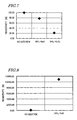
- FIG. 7 is a graph showing the resistivity of an oxide semiconductor layer, with respect to: the case where silica/barium oxide (SiO 2 ⁇ BaO) is added to 5 wt%; the case where silica/alumina (SiO 2 ⁇ Al 2 O 3 ) is added to 5 wt%; and the case where it is not added at all.
- silica/barium oxide SiO 2 ⁇ BaO
- silica/alumina SiO 2 ⁇ Al 2 O 3
- FIG. 8 is a graph showing the resistivity of an oxide semiconductor layer, with respect to: the case where silica/calcium oxide (SiO 2 ⁇ CaO) is added to 5 wt%; and the case where it is not added at all.
- FIGS. 9A and 9B are perspective views schematically showing a construction for affixing a gas sensor 10 to an exhaust pipe, where FIG. 9A shows a protection cap being unattached, and FIG. 9B shows a protection cap being attached.
- FIG. 10 is a cross-sectional view schematically showing a construction for affixing a gas sensor 10 to an exhaust pipe.
- FIG. 11 is a diagram schematically showing an exemplary motorcycle incorporating the gas sensor 10.
- FIG. 12 is a diagram schematically showing a control system of an engine in the motorcycle shown in FIG. 11.
- FIG. 13 is a flowchart showing an exemplary flow of control for the gas sensor 10.
- FIGS. 1 and 2 are an exploded perspective view and a cross-sectional view, respectively, schematically showing the gas sensor 10.
- the gas sensor 10 is a resistance-type oxygen sensor having an oxide semiconductor layer 11 which is composed of an oxide containing cerium and detection electrodes 12 for detecting the resistivity of the oxide semiconductor layer 11.
- the oxide semiconductor layer 11 and the detection electrodes 12 are supported by a substrate 13.
- the substrate 13 is formed of an insulator such as alumina or magnesia.
- the substrate 13 has a principal face 13a and a rear face 13b opposing each other, such that the oxide semiconductor layer 11 and the detection electrodes 12 are disposed on the principal face 13a.
- the oxide semiconductor layer 11 has a porous structure, and releases or absorbs oxygen in accordance with the oxygen partial pressure in the atmosphere. This causes a change in the oxygen vacancy concentration in the oxide semiconductor layer 11, which in turn causes a change in the resistivity of the oxide semiconductor layer 11. By measuring this change in resistivity with the detection electrodes 12, the oxygen concentration can be detected.
- cerium oxide or a composite of cerium oxide and zirconium oxide can be used, for example.
- an oxide which contains zirconium in addition to cerium an improved detection accuracy is obtained as described in Japanese Laid-open Patent Publication No. 2004-93547 , supra.
- the typical oxide semiconductor layer 11 dominantly includes cerium oxide (i.e., no less than 50 mol% of cerium oxide).
- the detection electrodes 12 is formed of an electrically conductive material, e.g., a metal material such as platinum, platinum-rhodium alloy, or gold.
- the detection electrodes 12 are shaped in the form of combteeth in order to enable efficiently measurement of changes in the resistivity of the oxide semiconductor layer 11.
- the heater 14 is a heating device of a resistance heating type, which performs heating by utilizing resistance loss.
- a voltage is applied to electrodes 14a which extend from the heater 14, an electric current flows in the heating element that is formed in a predetermined shape, whereby the heating element generates heat.
- the heat is conducted to the oxide semiconductor layer 11 via the substrate 13.
- the heating element is often formed of a metal material.
- the oxide semiconductor layer 11 of the gas sensor 10 of the present embodiment is composed by stacking: an alumina-containing layer 11a to which alumina is added; and a non-alumina-containing layer 11b to which no alumina is added.
- the oxide semiconductor layer 11 includes the alumina-containing layer 11a in which alumina is contained.
- the detection electrodes 12 are in contact with the alumina-containing layer 11a. Stated otherwise, along the thickness direction of the gas sensor 10 (i.e., a direction perpendicular to the principal face 13a of the substrate 13), there are the detection electrodes 12, the alumina-containing layer 11a, and the non-alumina-containing layer 11b, which are stacked in this order. Thus, the alumina-containing layer 11a is disposed on the side of the oxide semiconductor layer 11 facing the detection electrodes 12.
- the detection accuracy of the gas sensor 10 is improved when the oxide semiconductor layer 11 includes the alumina-containing layer 11a as such. The reason thereof will be described below.
- the inventor has conducted various studies for improving the detection accuracy of resistance-type gas sensors, and discovered a surprising phenomenon that adding alumina to an oxide containing cerium actually reduces the resistivity of the oxide semiconductor layer.
- Alumina is known to have a high electrical insulation ability, and conventionally, alumina has never been used for the purpose of reducing the electrical resistance of any material. Needless to say, no instances have been reported of an oxide semiconductor for a gas sensor where alumina is added for the purpose of reducing its resistivity.
- FIG. 3 shows results of prototyping the gas sensor 10 according to the present embodiment and measuring the resistivity (i.e., sensor output) of the oxide semiconductor layer 11 while varying the added amount of alumina (i.e., weight fraction of alumina in the alumina-containing layer 11a) .
- alumina i.e., weight fraction of alumina in the alumina-containing layer 11a
- ⁇ is shown on the horizontal axis
- sensor output is shown in logarithm on the vertical axis.
- resistivity is greatly reduced on the rich side because of the addition of alumina.
- the sensor output has a large oxygen partial pressure dependence, whereby the detection accuracy is improved.
- FIG. 4 shows a relationship between the resistivity of the oxide semiconductor layer 11 on the rich side and the added amount of alumina.
- resistivity is shown by relative values, defining the resistivity when the added amount of alumina is 0 wt% to be 100%.
- the resistivity of the oxide semiconductor layer 11 can be made sufficiently low, i.e., 20% or less.
- the gas sensor 10 of the present embodiment can be produced as follows, for example.
- the substrate 13 has an insulative surface, and preferably has a heat resistance such that it experiences substantially no deformation or the like at the temperature of a heat treatment which is performed in the following process or at the temperature at which the gas sensor 10 is to be used.
- alumina substrate having a thickness of 0.635 mm, a width of 5 mm, and a length of 15 mm was used.
- the detection electrodes 12 are formed on the principal face 13a of the substrate 13.
- the detection electrodes 12 are made of a material which is electrically conductive and which has a heat resistance similar to that of the substrate 13.
- a screen printing technique can be employed, for example.
- the detection electrodes 12 were formed so as to have a thickness of 8 ⁇ m, a width of 100 ⁇ m and a distance of 100 ⁇ m in between adjacent combteeth of the electrodes.
- the oxide semiconductor layer 11 is formed so as to cover the detection electrodes 12.
- two kinds of slurries containing particles of oxide semiconductor are prepared first: one of the slurries includes alumina particles added thereto, whereas the other slurry includes no alumina particles added thereto.
- the slurry including alumina particles added thereto is applied on the principal face 13a of the substrate 13 so as to cover the detection electrodes 12, and thereafter subjected to baking, thereby forming the alumina-containing layer 11a having a porous structure.
- the slurry including no alumina particles added thereto is applied on the alumina-containing layer 11a, and thereafter subjected to baking, thereby forming the non-alumina-containing layer 11b having a porous structure.
- the oxide semiconductor layer 11 is formed.
- a slurry including particles (average grain size: 10 nm to 50 nm) of a composite oxide whose main component is cerium and which has 20 mol% zirconium added thereto (expressed by the chemical formula Ce 0.8 Zr 0.2 O 2- ⁇ ) was used to form the non-alumina-containing layer 11b so as to have a thickness of 5 ⁇ m after baking.
- a slurry obtained by further adding 5 mol% alumina (average grain size: 200 nm to 800 nm) to the aforementioned slurry for the non-alumina-containing layer 11b was used to form the alumina-containing layer 11a so as to have a thickness of 5 ⁇ m after baking.
- the heater 14 is formed on the rear face 13b of the substrate 13.
- a metal material such as platinum or tungsten can also be used.
- a nonmetal material can also be used, e.g., an oxide conductor such as rhenium oxide can be used.
- a screen printing technique is suitably used.
- the gas sensor 10 can be produced in the above-described manner. Although the present embodiment illustrates a construction (as shown in FIG. 2) in which only a portion of the oxide semiconductor layer 11 is the alumina-containing layer 11a, it must be noted that the entire oxide semiconductor layer 11 may be the alumina-containing layer 11a (as shown in FIG. 5 ).
- FIG. 6 shows the resistivity of the oxide semiconductor layer 11 (where the vertical axis is in logarithm) with respect to: the case where only a portion of the oxide semiconductor layer 11 is the alumina-containing layer 11a (i.e., alumina is only present near the detection electrodes 12); and the case where the entire oxide semiconductor layer 11 is the alumina-containing layer 11a (i.e., alumina permeates the entire oxide semiconductor layer 11 ).
- the construction in which only a portion (i.e., a portion near the detection electrodes 12) of the oxide semiconductor layer 11 is the alumina-containing layer 11a provides a lower resistivity. This is presumably because, when the alumina particles permeate the entire oxide semiconductor layer 11, the oxygen within exhaust gas is prevented from being taken into oxygen vacancies. As shown in FIG. 2, by ensuring that only a portion of the oxide semiconductor layer 11 is the alumina-containing layer 11a while any other portion that is in contact with the exhaust gas is the non-alumina-containing layer 11b, oxygen is advantageously taken into the oxygen vacancies, whereby the resistance of the oxide semiconductor layer 11 can be further lowered.
- the above description is directed to an exemplary case where the alumina concentration within the oxide semiconductor layer 11 changes between two levels along the thickness direction of the gas sensor 10 (construction shown in FIG. 2) or an exemplary case where it is substantially constant (construction shown in FIG. 5).
- the alumina concentration within the oxide semiconductor layer 11 may change in three or more levels along the thickness direction of the gas sensor 10, or may vary linearly (gradually).
- the alumina concentration in the oxide semiconductor layer 11 is higher near the detection electrodes 12 than near the surface of the gas sensor 10.
- the oxide semiconductor layer 11 has a porous structure including particles of an oxide semiconductor.
- the response of the gas sensor 10 can be improved by ensuring that the particles of an oxide semiconductor containing cerium have a small average grain size, specifically 200 nm or less, because this reduces the travel distance of oxygen vacancies within the particles and increases the surface area of the oxide semiconductor, whereby the response time of an output which is made in response to a change in oxygen concentration is reduced.
- the oxide semiconductor particles will bind to one another at an increased number of sites, thus producing the effect of improving the mechanical strength of the porous structure.
- the average grain size of alumina particles is preferably larger than the average grain size of oxide semiconductor particles.
- the relatively small oxide semiconductor particles will be positioned so as to surround the relatively large alumina particles, whereby the oxide semiconductor particles are prevented from taking an overly dense positioning.
- the porous structure has an increased porosity.
- FIG. 7 shows resistivity (relative values) in the case where silica/barium oxide (SiO 2 ⁇ BaO) is added to 5 wt%, instead of alumina.
- SiO 2 ⁇ BaO silica/barium oxide
- FIG. 7 also shows resistivity in the case where silica/alumina (SiO 2 ⁇ Al 2 O 3 ) is added to 5 wt%, instead of alumina.
- silica/alumina SiO 2 ⁇ Al 2 O 3
- the resistivity is greatly reduced by adding silica/alumina than when it is not added at all.
- alumina may be added in the form of a composite such as silica/alumina to the oxide semiconductor layer 11. In other words, it suffices if a whole or part of the oxide semiconductor layer 11 contains alumina as a component. Note that, in the example shown in FIG. 7, alumina accounts for 1/4 of the entire silica/alumina that has been added, which means that this addition of silica/alumina is equivalent to alumina being added to an amount of 1.25 wt%.
- FIG. 8 shows resistivity (relative values) in the case where silica/calcium oxide (SiO 2 ⁇ CaO) is added to 5 wt%, instead of alumina.
- the resistivity is increased by 100 times or more by adding silica/calcium oxide than when it is not added at all. This also indicates that alumina is preferable for reducing the resistivity of the oxide semiconductor layer 11.
- the gas sensor 10 is held by a first housing 20, as shown in FIGS. 9A and 10.
- the first housing 20 is a ceramic guide which is made of a ceramic material, for example.
- the first housing 20 carrying the gas sensor 10 is held in place by a second housing 21.
- the second housing 21 is a metal case which is made of stainless steel, for example.
- the surface of the second housing 21 is threaded, and the second housing 21 is affixed to an exhaust pipe with a nut 22 which engages with the threading.
- a protection cap 25 is provided so as to cover the gas sensor 10.
- the result of detection by the gas sensor 10 is output to a control device via a detection line 24.
- the inside of the first housing 20 is sealed in an airtight manner by using a filler (e.g., talc powder) 23.
- FIG. 11 schematically shows a motorcycle 300 incorporating the gas sensor 10.
- the motorcycle 300 includes a body frame 301 and an engine (internal combustion engine) 100.
- a head pipe 302 is provided at the front end of the body frame 301.
- a front fork 303 is attached so as to be capable of swinging in the right-left direction.
- a front wheel 304 is supported so as to be capable of rotating.
- Handle bars 305 are attached to the upper end of the head pipe 302.
- a seat rail 306 is attached at an upper portion of the rear end of the body frame 301 so as to extend in the rear direction.
- a fuel tank 307 is provided above the body frame 301, and a main seat 308a and a tandem seat 308b are provided on the seat rail 306.
- rear arms 309 extending in the rear direction are attached to the rear end of the body frame 301. At the rear end of the rear arms 309, a rear wheel 310 is supported so as to be capable of rotating.
- the engine 100 is held at the central portion of the body frame 301.
- a radiator 311 is provided in front of the engine 100.
- An exhaust pipe 312 is connected to an exhaust port of the engine 100.
- a gas sensor 10, a ternary-type catalyst 104, and a muffler 106 are provided on the exhaust pipe (in an ascending order of distance from the engine 100).
- the top end of the gas sensor 10 is exposed in a passage within the exhaust pipe 312 in which exhaust gas travels.
- the gas sensor 10 detects oxygen within the exhaust gas.
- the gas sensor 10 has the heater 14 as shown in FIG. 1, etc., attached thereto. As the temperature of the oxide semiconductor layer 11 is elevated by the heater 14 at the start of the engine 100 (e.g., elevated to 700 °C in 5 seconds), the detection sensitivity of the oxide semiconductor layer 11 is enhanced.
- a transmission 315 is linked to the engine 100.
- Driving sprockets 317 are attached on an output axis 316 of the transmission 315. Via a chain 318, the driving sprockets 317 are linked to rear wheel sprockets 319 of the rear wheel 310.
- FIG. 12 shows main component elements of a control system of the engine 100.
- an intake valve 110 On a cylinder 101 of the engine 100, an intake valve 110, an exhaust valve 106, and a spark plug 108 are provided.
- a water temperature sensor 116 for measuring the water temperature of the cooling water with which to cool the engine.
- the intake valve 110 is connected to an intake manifold 122, which has an air intake.
- an airflow meter 112 On the intake manifold 122, an airflow meter 112, a throttle sensor 114 for a throttle valve, and a fuel injector 111 are provided.
- the airflow meter 112, the throttle sensor 114, the fuel injector 111, the water temperature sensor 116, the spark plug 108, and the gas sensor 10 are connected to a computer 118, which is the control section.
- a vehicle velocity signal 120, which represents the velocity of the motorcycle 300, is also input to the computer 118.
- the computer 118 calculates an optimum fuel amount based on detection signals and the vehicle velocity signal 120 obtained from the airflow meter 112, the throttle sensor 114, and the water temperature sensor 116, and based on the result of calculation, outputs a control signal to the fuel injector 111.
- the fuel which is injected from the fuel injector 111 is mixed with the air which is supplied from the intake manifold 122, and injected into the cylinder 101 via the intake valve 110, which is opened or closed with appropriate timing.
- the fuel which is injected in the cylinder 101 combusts to become exhaust gas, which is led to the exhaust pipe 312 via the exhaust valve 106.
- the gas sensor 10 detects the oxygen in the exhaust gas, and outputs a detection signal to the computer 118. Based on the signal from the gas sensor 10, the computer 118 determines the amount of deviation of the air-fuel ratio from an ideal air-fuel ratio. Then, the amount of fuel which is injected from the fuel injector 111 is controlled so as to attain the ideal air-fuel ratio relative to the air amount which is known from the signals obtained from the flowmeter 112 and the throttle sensor 114.
- an air-fuel ratio controller which includes the gas sensor 10 and the computer (control section) 118 connected to the gas sensor 10 appropriately controls the air-fuel ratio of the internal combustion engine.
- FIG. 13 shows a flow of control for the heater 14 of the gas sensor 10.
- the heater 14 begins to be powered (step S2).
- the temperature of the heater 14 is detected (step S3), and it is determined whether the temperature of the heater 14 is lower than a set temperature or not (step S4). Detection of the temperature of the heater 14 can be performed by, utilizing the fact that the resistance value of the heater 14 changes depending on temperature, detecting the electric current which flows in the heater 14. If the temperature of the heater 14 is lower than the set temperature, the heater 14 continues to be powered (step S2 ).
- step S5 if the temperature of the heater 14 is equal to or greater than the set temperature, powering of the heater 14 is stopped for a certain period of time (step S5), and after resuming powering of the heater 14 (step S2) , the temperature of the heater 14 is detected (step S3). Through such a flow of control, the temperature of the heater 14 is kept constant.
- the oxygen concentration within the exhaust gas and changes therein can be detected with a good detection accuracy. This ensures that, even at the start, fuel and air are mixed at an appropriate air-fuel ratio, and allow the fuel to combust under optimum conditions, whereby the concentration of regulated substances (e.g., NO x ) within the exhaust gas can be reduced. It is also possible to obtain improved mileage.
- regulated substances e.g., NO x
- the present invention can also be suitably used for any other transportation apparatus, e.g., a four-wheeled automobile.
- the internal combustion engine is not limited to a gasoline engine, but may alternatively be a diesel engine.
- the detection accuracy of a resistance-type gas sensor having an oxide semiconductor layer which is composed of an oxide containing cerium can be improved.
- the gas sensor according to the present invention has an excellent detection accuracy, and therefore is suitably used in an internal combustion engine for various transportation apparatuses, e.g., a car, a bus, a truck, a motorbike, a tractor, an airplane, a motorboat, a vehicle for civil engineering use, or the like.
Landscapes
- Chemical & Material Sciences (AREA)
- Chemical Kinetics & Catalysis (AREA)
- Electrochemistry (AREA)
- Physics & Mathematics (AREA)
- Health & Medical Sciences (AREA)
- Life Sciences & Earth Sciences (AREA)
- Analytical Chemistry (AREA)
- Biochemistry (AREA)
- General Health & Medical Sciences (AREA)
- General Physics & Mathematics (AREA)
- Immunology (AREA)
- Pathology (AREA)
- Investigating Or Analyzing Materials By The Use Of Fluid Adsorption Or Reactions (AREA)
Abstract
Description
- The present invention relates to a gas sensor, and in particular to a resistance-type gas sensor having an oxide semiconductor layer. Moreover, the present invention also relates to an internal combustion engine and a transportation apparatus incorporating such a gas sensor.
- From the standpoint of environmental issues and energy issues, it has been desired to improve the mileage of internal combustion engines, and reduce the emission amount of regulated substances (e.g., NOx) that are contained within exhaust gas from internal combustion engines. In order to meet these needs, it is necessary to appropriately control the ratio between fuel and air in accordance with the state of combustion, so that fuel combustion will occur always under optimum conditions. The ratio of air to fuel is called an "air-fuel ratio" (A/F). In the case where a ternary catalyst is employed, the optimum air-fuel ratio would be the stoichiometric air-fuel ratio. The "stoichiometric air-fuel ratio" is an air-fuel ratio at which air and fuel will combust just sufficiently.
- When fuel is combusting at the stoichiometric air-fuel ratio, a certain amount of oxygen is contained within the exhaust gas. When the air-fuel ratio is smaller than the stoichiometric air-fuel ratio (i.e., the fuel concentration is high), the oxygen amount in the exhaust gas decreases relative to that under the stoichiometric air-fuel ratio. On the other hand, when the air-fuel ratio is greater than the stoichiometric air-fuel ratio (i.e., the fuel concentration is low), the oxygen amount in the exhaust gas increases. Therefore, by measuring the oxygen amount or oxygen concentration in the exhaust gas, it is possible to estimate how much deviation the air-fuel ratio has relative to the stoichiometric air-fuel ratio. This makes it possible to adjust the air-fuel ratio and control the fuel combustion so as to occur under the optimum conditions.
- As oxygen sensors for measuring the oxygen concentration in exhaust gas, oxygen sensors comprising a solid electrolyte as disclosed in
Japanese Laid-Open Patent Publication No. 8-114571 Japanese Laid-Open Patent Publication No. 5-18921 - An oxygen sensor comprising a solid electrolyte measures oxygen concentration by measuring a difference in oxygen partial pressure between a reference electrode and a measuring electrode as an electromotive force. Therefore, in this type of oxygen sensor, it is necessary to expose the measuring electrode and the reference electrode to exhaust gas and air, respectively. This complicates the structure of the oxygen sensor itself, and also complicates any structure which may be employed for attaching the oxygen sensor to an exhaust pipe. The complicated structure also makes it difficult to downsize the oxygen sensor.
- On the other hand, a resistance-type oxygen sensor detects changes in the resistivity of an oxide semiconductor layer which is provided so as to be in contact with exhaust gas. When the oxygen partial pressure within the exhaust gas changes, the oxygen vacancy concentration in the oxide semiconductor layer fluctuates, thus causing a change in the resistivity of the oxide semiconductor layer. Therefore, by detecting such a change in resistivity, the oxygen concentration can be measured. Since a resistance-type oxygen sensor does not require a reference electrode, the structure of the oxygen sensor itself can be simplified. Moreover, the structure which may be employed for attaching the oxygen sensor to an exhaust pipe can also be simplified.
- As the oxide semiconductor to be employed for a resistance-type oxygen sensor, cerium oxide is considered as promising in terms of durability and stability. As disclosed in
Japanese Laid-Open Patent Publication No. 2003-149189 - As is disclosed in
Japanese Laid-open Patent Publication No. 2004-93547 - However, due to the increased concerns on environmental issues in the recent years, there has been a desire to detect oxygen concentration with an even higher accuracy.
- The present invention has been made in view of the above problems, and an objective thereof is to improve the detection accuracy of a resistance-type gas sensor comprising an oxide semiconductor layer which is composed of an oxide containing cerium.
- A gas sensor according to the present invention is a gas sensor of a resistance-type, comprising: an oxide semiconductor layer composed of an oxide containing cerium; and detection electrodes for detecting a resistivity of the oxide semiconductor layer, wherein, the oxide semiconductor layer includes an alumina-containing layer in which alumina is contained; and the detection electrodes are disposed in contact with the alumina-containing layer. Thus, the aforementioned objective is met.
- In a preferred embodiment, the alumina-containing layer contains alumina to an amount of no less than 4.5 wt% and no more than 12 wt%.
- In a preferred embodiment, only a portion of the oxide semiconductor layer is the alumina-containing layer.
- In a preferred embodiment, the entire oxide semiconductor layer is the alumina-containing layer.
- In a preferred embodiment, the oxide semiconductor layer has a porous structure containing oxide semiconductor particles, the oxide semiconductor particles having an average grain size of 200 nm or less.
- In a preferred embodiment, the alumina-containing layer has a porous structure containing oxide semiconductor particles and alumina particles, the alumina particles having an average grain size which is greater than an average grain size of the oxide semiconductor particles.
- In a preferred embodiment, the oxide composing the oxide semiconductor layer further contains zirconium.
- Alternatively, a gas sensor according to the present invention is a gas sensor of a resistance-type, comprising: an oxide semiconductor layer composed of an oxide containing cerium; and detection electrodes for detecting a resistivity of the oxide semiconductor layer, wherein, the oxide semiconductor layer contains alumina; and the alumina contained in the oxide semiconductor layer has a concentration distribution such that the alumina has a relatively high concentration near the detection electrode. Thus, the aforementioned objective is met.
- In a preferred embodiment, the gas sensor according to the present invention is an oxygen sensor.
- An internal combustion engine according to the present invention comprises a gas sensor having the above construction.
- A transportation apparatus according to the present invention comprises an internal combustion engine having the above construction.
- A gas sensor according to the present invention is a resistance-type gas sensor having an oxide semiconductor layer which is composed of an oxide containing cerium. In the gas sensor according to the present invention, the oxide semiconductor layer includes an alumina-containing layer in which alumina is contained, and detection electrodes are disposed in contact with the alumina-containing layer. As a result, the resistivity of the oxide semiconductor layer when in an atmosphere with a low oxygen partial pressure (i.e., fuel-rich side) is reduced, so that the sensor output has a greater oxygen partial pressure dependence. Thus, the detection accuracy is improved.
- Other features, elements, processes, steps, characteristics and advantages of the present invention will become more apparent from the following detailed description of preferred embodiments of the present invention with reference to the attached drawings.
- FIG. 1 is an exploded perspective view schematically showing a
gas sensor 10 according to a preferred embodiment of the present invention. - FIG. 2 is a cross-sectional view schematically showing a
gas sensor 10 according to a preferred embodiment of the present invention. - FIG. 3 is a graph showing a relationship between lambda (λ) and sensor output (resistivity of an oxide semiconductor layer) when a varying amount of alumina is added, where the vertical axis is in logarithm.
- FIG. 4 is a graph showing a relationship between resistivity and added amounts of alumina, on the rich side, of an oxide semiconductor layer.
- FIG. 5 is a cross-sectional view schematically showing a
gas sensor 10 according to a preferred embodiment of the present invention. - FIG. 6 is a graph showing a relationship between lambda (λ) and sensor output (resistivity of an oxide semiconductor layer), where the vertical axis is in logarithm, with respect to: the case where only a portion of the oxide semiconductor layer is an alumina-containing layer; and the case where the entire oxide semiconductor layer is an alumina-containing layer.
- FIG. 7 is a graph showing the resistivity of an oxide semiconductor layer, with respect to: the case where silica/barium oxide (SiO2·BaO) is added to 5 wt%; the case where silica/alumina (SiO2·Al2O3) is added to 5 wt%; and the case where it is not added at all.
- FIG. 8 is a graph showing the resistivity of an oxide semiconductor layer, with respect to: the case where silica/calcium oxide (SiO2·CaO) is added to 5 wt%; and the case where it is not added at all.
- FIGS. 9A and 9B are perspective views schematically showing a construction for affixing a
gas sensor 10 to an exhaust pipe, where FIG. 9A shows a protection cap being unattached, and FIG. 9B shows a protection cap being attached. - FIG. 10 is a cross-sectional view schematically showing a construction for affixing a
gas sensor 10 to an exhaust pipe. - FIG. 11 is a diagram schematically showing an exemplary motorcycle incorporating the
gas sensor 10. - FIG. 12 is a diagram schematically showing a control system of an engine in the motorcycle shown in FIG. 11.
- FIG. 13 is a flowchart showing an exemplary flow of control for the
gas sensor 10. - Hereinafter, a preferred embodiment of the present invention will be described with reference to the accompanying drawings. Note that the present invention is not to be limited to the following embodiment.
- First, with reference to FIGS. 1 and 2, the structure of a
gas sensor 10 according to the present embodiment will be described. FIGS. 1 and 2 are an exploded perspective view and a cross-sectional view, respectively, schematically showing thegas sensor 10. As shown in FIGS. 1 and 2, thegas sensor 10 is a resistance-type oxygen sensor having anoxide semiconductor layer 11 which is composed of an oxide containing cerium anddetection electrodes 12 for detecting the resistivity of theoxide semiconductor layer 11. - The
oxide semiconductor layer 11 and thedetection electrodes 12 are supported by asubstrate 13. Thesubstrate 13 is formed of an insulator such as alumina or magnesia. Thesubstrate 13 has aprincipal face 13a and arear face 13b opposing each other, such that theoxide semiconductor layer 11 and thedetection electrodes 12 are disposed on theprincipal face 13a. - The
oxide semiconductor layer 11 has a porous structure, and releases or absorbs oxygen in accordance with the oxygen partial pressure in the atmosphere. This causes a change in the oxygen vacancy concentration in theoxide semiconductor layer 11, which in turn causes a change in the resistivity of theoxide semiconductor layer 11. By measuring this change in resistivity with thedetection electrodes 12, the oxygen concentration can be detected. - As an oxide composing the
oxide semiconductor layer 11, cerium oxide or a composite of cerium oxide and zirconium oxide can be used, for example. By using an oxide which contains zirconium in addition to cerium, an improved detection accuracy is obtained as described inJapanese Laid-open Patent Publication No. 2004-93547 oxide semiconductor layer 11 dominantly includes cerium oxide (i.e., no less than 50 mol% of cerium oxide). - The
detection electrodes 12 is formed of an electrically conductive material, e.g., a metal material such as platinum, platinum-rhodium alloy, or gold. Preferably, thedetection electrodes 12 are shaped in the form of combteeth in order to enable efficiently measurement of changes in the resistivity of theoxide semiconductor layer 11. - On the
rear face 13b side of thesubstrate 13, aheater 14 for elevating the temperature of theoxide semiconductor layer 11 is provided. In the present embodiment, theheater 14 is a heating device of a resistance heating type, which performs heating by utilizing resistance loss. When a voltage is applied toelectrodes 14a which extend from theheater 14, an electric current flows in the heating element that is formed in a predetermined shape, whereby the heating element generates heat. The heat is conducted to theoxide semiconductor layer 11 via thesubstrate 13. The heating element is often formed of a metal material. By elevating the temperature of theoxide semiconductor layer 11 with theheater 14 to enable quick activation, the detection accuracy at the start of the internal combustion engine can be improved. - As shown in FIG. 2, the
oxide semiconductor layer 11 of thegas sensor 10 of the present embodiment is composed by stacking: an alumina-containinglayer 11a to which alumina is added; and a non-alumina-containinglayer 11b to which no alumina is added. In other words, theoxide semiconductor layer 11 includes the alumina-containinglayer 11a in which alumina is contained. Thedetection electrodes 12 are in contact with the alumina-containinglayer 11a. Stated otherwise, along the thickness direction of the gas sensor 10 (i.e., a direction perpendicular to theprincipal face 13a of the substrate 13), there are thedetection electrodes 12, the alumina-containinglayer 11a, and the non-alumina-containinglayer 11b, which are stacked in this order. Thus, the alumina-containinglayer 11a is disposed on the side of theoxide semiconductor layer 11 facing thedetection electrodes 12. - The detection accuracy of the
gas sensor 10 is improved when theoxide semiconductor layer 11 includes the alumina-containinglayer 11a as such. The reason thereof will be described below. - The inventor has conducted various studies for improving the detection accuracy of resistance-type gas sensors, and discovered a surprising phenomenon that adding alumina to an oxide containing cerium actually reduces the resistivity of the oxide semiconductor layer. Alumina is known to have a high electrical insulation ability, and conventionally, alumina has never been used for the purpose of reducing the electrical resistance of any material. Needless to say, no instances have been reported of an oxide semiconductor for a gas sensor where alumina is added for the purpose of reducing its resistivity.
- FIG. 3 shows results of prototyping the
gas sensor 10 according to the present embodiment and measuring the resistivity (i.e., sensor output) of theoxide semiconductor layer 11 while varying the added amount of alumina (i.e., weight fraction of alumina in the alumina-containinglayer 11a) . In the graph of FIG. 3, lambda (λ) is shown on the horizontal axis, whereas sensor output is shown in logarithm on the vertical axis. Lambda (λ) is a value indicating how deviated an actual air-fuel ratio is from a stoichiometric air-fuel ratio, as expressed by the formula: λ=(supplied air amount)/(theoretically required air amount). When λ =1 (i.e., center of the graph), the air-fuel ratio is equal to the stoichiometric air-fuel ratio. On the other hand, when λ<1 (i.e., left-hand side of the graph), the supplied air amount is insufficient, so that the mixture is dense ("rich" side). When λ>1 (i.e., right-hand side of the graph), the supplied air amount is excessive, so that the mixture is thin ("lean" side). - As can be seen from FIG. 3, resistivity is greatly reduced on the rich side because of the addition of alumina. As a result, the sensor output has a large oxygen partial pressure dependence, whereby the detection accuracy is improved. Although the mechanism by which the addition of alumina reduces the resistivity of the
oxide semiconductor layer 11 is not clear, it has been experimentally confirmed that the resistivity does lower on the rich side. - FIG. 4 shows a relationship between the resistivity of the
oxide semiconductor layer 11 on the rich side and the added amount of alumina. In FIG. 4, resistivity is shown by relative values, defining the resistivity when the added amount of alumina is 0 wt% to be 100%. - As shown in FIG. 4, when the added amount of alumina is between 0 wt% and about 5 wt%, the resistivity greatly decreases as the amount of alumina increases. When the added amount of alumina exceeds about 5 wt%, the resistivity slightly increases as the amount of alumina increases. As can be seen from FIG. 4, by ensuring that the alumina content in the alumina-containing
layer 11a is no less than 4.5 wt% and no more than 12 wt%, the resistivity of theoxide semiconductor layer 11 can be made sufficiently low, i.e., 20% or less. - The
gas sensor 10 of the present embodiment can be produced as follows, for example. - First, the
substrate 13 is provided. Thesubstrate 13 has an insulative surface, and preferably has a heat resistance such that it experiences substantially no deformation or the like at the temperature of a heat treatment which is performed in the following process or at the temperature at which thegas sensor 10 is to be used. For the prototype gas sensor whose data is shown in FIGS. 3 and 4, an alumina substrate having a thickness of 0.635 mm, a width of 5 mm, and a length of 15 mm was used. - Next, the
detection electrodes 12 are formed on theprincipal face 13a of thesubstrate 13. Thedetection electrodes 12 are made of a material which is electrically conductive and which has a heat resistance similar to that of thesubstrate 13. As a method for forming theelectrodes 12, a screen printing technique can be employed, for example. In the prototype, after a platinum paste was applied on theprincipal face 13a by a screen printing technique, baking was performed, whereby thedetection electrodes 12 were formed so as to have a thickness of 8 µm, a width of 100 µm and a distance of 100 µm in between adjacent combteeth of the electrodes. - Next, the
oxide semiconductor layer 11 is formed so as to cover thedetection electrodes 12. Specifically, two kinds of slurries containing particles of oxide semiconductor are prepared first: one of the slurries includes alumina particles added thereto, whereas the other slurry includes no alumina particles added thereto. - Next, the slurry including alumina particles added thereto is applied on the
principal face 13a of thesubstrate 13 so as to cover thedetection electrodes 12, and thereafter subjected to baking, thereby forming the alumina-containinglayer 11a having a porous structure. - Then, the slurry including no alumina particles added thereto is applied on the alumina-containing
layer 11a, and thereafter subjected to baking, thereby forming the non-alumina-containinglayer 11b having a porous structure. Thus, theoxide semiconductor layer 11 is formed. - In the prototype, a slurry including particles (average grain size: 10 nm to 50 nm) of a composite oxide whose main component is cerium and which has 20 mol% zirconium added thereto (expressed by the chemical formula Ce0.8Zr0.2O2-δ) was used to form the non-alumina-containing
layer 11b so as to have a thickness of 5 µm after baking. Moreover, a slurry obtained by further adding 5 mol% alumina (average grain size: 200 nm to 800 nm) to the aforementioned slurry for the non-alumina-containinglayer 11b was used to form the alumina-containinglayer 11a so as to have a thickness of 5µm after baking. - In addition to forming the
detection electrodes 12 and theoxide semiconductor layer 11 on theprincipal face 13a of thesubstrate 13 as described above, theheater 14 is formed on therear face 13b of thesubstrate 13. As the material of theheater 14, a metal material such as platinum or tungsten can also be used. Moreover, a nonmetal material can also be used, e.g., an oxide conductor such as rhenium oxide can be used. As a method for forming theheater 14, a screen printing technique is suitably used. - The
gas sensor 10 can be produced in the above-described manner. Although the present embodiment illustrates a construction (as shown in FIG. 2) in which only a portion of theoxide semiconductor layer 11 is the alumina-containinglayer 11a, it must be noted that the entireoxide semiconductor layer 11 may be the alumina-containinglayer 11a (as shown in FIG. 5). - From the standpoint of lowering the resistance of the
oxide semiconductor layer 11, it is preferable that alumina is only present near thedetection electrodes 12. In other words, it is preferable that only a portion of theoxide semiconductor layer 11 is the alumina-containinglayer 11a. FIG. 6 shows the resistivity of the oxide semiconductor layer 11 (where the vertical axis is in logarithm) with respect to: the case where only a portion of theoxide semiconductor layer 11 is the alumina-containinglayer 11a (i.e., alumina is only present near the detection electrodes 12); and the case where the entireoxide semiconductor layer 11 is the alumina-containinglayer 11a (i.e., alumina permeates the entire oxide semiconductor layer 11). - As can be seen from FIG. 6, the construction in which only a portion (i.e., a portion near the detection electrodes 12) of the
oxide semiconductor layer 11 is the alumina-containinglayer 11a provides a lower resistivity. This is presumably because, when the alumina particles permeate the entireoxide semiconductor layer 11, the oxygen within exhaust gas is prevented from being taken into oxygen vacancies. As shown in FIG. 2, by ensuring that only a portion of theoxide semiconductor layer 11 is the alumina-containinglayer 11a while any other portion that is in contact with the exhaust gas is the non-alumina-containinglayer 11b, oxygen is advantageously taken into the oxygen vacancies, whereby the resistance of theoxide semiconductor layer 11 can be further lowered. - On the other hand, as shown in FIG. 5, by ensuring that the entire
oxide semiconductor layer 11 is the alumina-containinglayer 11a, production of thegas sensor 10 can be simplified and the costs thereof can be lowered because it is unnecessary to prepare two kinds of slurries and perform two application steps/two baking steps when forming theoxide semiconductor layer 11. - Note that the above description is directed to an exemplary case where the alumina concentration within the
oxide semiconductor layer 11 changes between two levels along the thickness direction of the gas sensor 10 (construction shown in FIG. 2) or an exemplary case where it is substantially constant (construction shown in FIG. 5). However, the alumina concentration within theoxide semiconductor layer 11 may change in three or more levels along the thickness direction of thegas sensor 10, or may vary linearly (gradually). However, from the standpoint of lowering the resistance of theoxide semiconductor layer 11, it is preferable to create a concentration distribution such that the alumina concentration is relatively low in a region of theoxide semiconductor layer 11 where it comes in contact with the exhaust gas (even if alumina is to be contained in the entire oxide semiconductor layer 11); that is, the alumina contained in theoxide semiconductor layer 11 preferably has a relatively high concentration near thedetection electrodes 12. Stated otherwise, it is preferable that the alumina concentration in theoxide semiconductor layer 11 is higher near thedetection electrodes 12 than near the surface of thegas sensor 10. - As has already been described, the
oxide semiconductor layer 11 has a porous structure including particles of an oxide semiconductor. The response of thegas sensor 10 can be improved by ensuring that the particles of an oxide semiconductor containing cerium have a small average grain size, specifically 200 nm or less, because this reduces the travel distance of oxygen vacancies within the particles and increases the surface area of the oxide semiconductor, whereby the response time of an output which is made in response to a change in oxygen concentration is reduced. Moreover, when the average grain size of oxide semiconductor particles is reduced, the oxide semiconductor particles will bind to one another at an increased number of sites, thus producing the effect of improving the mechanical strength of the porous structure. - Moreover, the average grain size of alumina particles is preferably larger than the average grain size of oxide semiconductor particles. When the average grain size of alumina particles is larger than the average grain size of oxide semiconductor particles, the relatively small oxide semiconductor particles will be positioned so as to surround the relatively large alumina particles, whereby the oxide semiconductor particles are prevented from taking an overly dense positioning. As a result, the porous structure has an increased porosity.
- The above descriptions are directed to the case where alumina is added to the
oxide semiconductor layer 11. FIG. 7 shows resistivity (relative values) in the case where silica/barium oxide (SiO2·BaO) is added to 5 wt%, instead of alumina. As can be seen from FIG. 7, the resistivity is not much reduced by adding silica/barium oxide than when it is not added at all. This indicates that alumina is particularly suitable for reducing the resistivity of theoxide semiconductor layer 11. - FIG. 7 also shows resistivity in the case where silica/alumina (SiO2·Al2O3) is added to 5 wt%, instead of alumina. As can be seen from FIG. 7, the resistivity is greatly reduced by adding silica/alumina than when it is not added at all. Thus, rather than being added alone, alumina may be added in the form of a composite such as silica/alumina to the
oxide semiconductor layer 11. In other words, it suffices if a whole or part of theoxide semiconductor layer 11 contains alumina as a component. Note that, in the example shown in FIG. 7, alumina accounts for 1/4 of the entire silica/alumina that has been added, which means that this addition of silica/alumina is equivalent to alumina being added to an amount of 1.25 wt%. - For reference, FIG. 8 shows resistivity (relative values) in the case where silica/calcium oxide (SiO2·CaO) is added to 5 wt%, instead of alumina. As can be seen from FIG. 8, the resistivity is increased by 100 times or more by adding silica/calcium oxide than when it is not added at all. This also indicates that alumina is preferable for reducing the resistivity of the
oxide semiconductor layer 11. - Next, with reference to FIGS. 9A and 9B and FIG. 10, a construction for actually attaching the
gas sensor 10 to an exhaust pipe of an internal combustion engine will be described. - At its base end, the
gas sensor 10 is held by afirst housing 20, as shown in FIGS. 9A and 10. Thefirst housing 20 is a ceramic guide which is made of a ceramic material, for example. Furthermore, thefirst housing 20 carrying thegas sensor 10 is held in place by asecond housing 21. Thesecond housing 21 is a metal case which is made of stainless steel, for example. The surface of thesecond housing 21 is threaded, and thesecond housing 21 is affixed to an exhaust pipe with anut 22 which engages with the threading. - In actual use, as shown in FIG. 9B, a
protection cap 25 is provided so as to cover thegas sensor 10. The result of detection by thegas sensor 10 is output to a control device via adetection line 24. The inside of thefirst housing 20 is sealed in an airtight manner by using a filler (e.g., talc powder) 23. - Next, a vehicle which incorporates the
gas sensor 10 according to the present embodiment and which employs an internal combustion engine as a driving source will be described. FIG. 11 schematically shows amotorcycle 300 incorporating thegas sensor 10. - As shown in FIG. 11, the
motorcycle 300 includes abody frame 301 and an engine (internal combustion engine) 100. Ahead pipe 302 is provided at the front end of thebody frame 301. To thehead pipe 302, afront fork 303 is attached so as to be capable of swinging in the right-left direction. At the lower end of thefront fork 303, afront wheel 304 is supported so as to be capable of rotating. Handle bars 305 are attached to the upper end of thehead pipe 302. - A
seat rail 306 is attached at an upper portion of the rear end of thebody frame 301 so as to extend in the rear direction. Afuel tank 307 is provided above thebody frame 301, and amain seat 308a and atandem seat 308b are provided on theseat rail 306. Moreover,rear arms 309 extending in the rear direction are attached to the rear end of thebody frame 301. At the rear end of therear arms 309, arear wheel 310 is supported so as to be capable of rotating. - The
engine 100 is held at the central portion of thebody frame 301. Aradiator 311 is provided in front of theengine 100. Anexhaust pipe 312 is connected to an exhaust port of theengine 100. As will be specifically described below, agas sensor 10, a ternary-type catalyst 104, and amuffler 106 are provided on the exhaust pipe (in an ascending order of distance from the engine 100). The top end of thegas sensor 10 is exposed in a passage within theexhaust pipe 312 in which exhaust gas travels. Thus, thegas sensor 10 detects oxygen within the exhaust gas. Thegas sensor 10 has theheater 14 as shown in FIG. 1, etc., attached thereto. As the temperature of theoxide semiconductor layer 11 is elevated by theheater 14 at the start of the engine 100 (e.g., elevated to 700 °C in 5 seconds), the detection sensitivity of theoxide semiconductor layer 11 is enhanced. - A
transmission 315 is linked to theengine 100. Drivingsprockets 317 are attached on anoutput axis 316 of thetransmission 315. Via achain 318, the drivingsprockets 317 are linked torear wheel sprockets 319 of therear wheel 310. - FIG. 12 shows main component elements of a control system of the
engine 100. On acylinder 101 of theengine 100, anintake valve 110, anexhaust valve 106, and aspark plug 108 are provided. There is also provided awater temperature sensor 116 for measuring the water temperature of the cooling water with which to cool the engine. Theintake valve 110 is connected to anintake manifold 122, which has an air intake. On theintake manifold 122, anairflow meter 112, athrottle sensor 114 for a throttle valve, and afuel injector 111 are provided. - The
airflow meter 112, thethrottle sensor 114, thefuel injector 111, thewater temperature sensor 116, thespark plug 108, and thegas sensor 10 are connected to acomputer 118, which is the control section. Avehicle velocity signal 120, which represents the velocity of themotorcycle 300, is also input to thecomputer 118. - When a rider starts the
engine 100 by using a self-starting motor (not shown), thecomputer 118 calculates an optimum fuel amount based on detection signals and thevehicle velocity signal 120 obtained from theairflow meter 112, thethrottle sensor 114, and thewater temperature sensor 116, and based on the result of calculation, outputs a control signal to thefuel injector 111. The fuel which is injected from thefuel injector 111 is mixed with the air which is supplied from theintake manifold 122, and injected into thecylinder 101 via theintake valve 110, which is opened or closed with appropriate timing. The fuel which is injected in thecylinder 101 combusts to become exhaust gas, which is led to theexhaust pipe 312 via theexhaust valve 106. - The
gas sensor 10 detects the oxygen in the exhaust gas, and outputs a detection signal to thecomputer 118. Based on the signal from thegas sensor 10, thecomputer 118 determines the amount of deviation of the air-fuel ratio from an ideal air-fuel ratio. Then, the amount of fuel which is injected from thefuel injector 111 is controlled so as to attain the ideal air-fuel ratio relative to the air amount which is known from the signals obtained from theflowmeter 112 and thethrottle sensor 114. Thus, an air-fuel ratio controller which includes thegas sensor 10 and the computer (control section) 118 connected to thegas sensor 10 appropriately controls the air-fuel ratio of the internal combustion engine. - FIG. 13 shows a flow of control for the
heater 14 of thegas sensor 10. When theengine 100 is started and the main switch is placed in an ON state (step S1), theheater 14 begins to be powered (step S2). Next, the temperature of theheater 14 is detected (step S3), and it is determined whether the temperature of theheater 14 is lower than a set temperature or not (step S4). Detection of the temperature of theheater 14 can be performed by, utilizing the fact that the resistance value of theheater 14 changes depending on temperature, detecting the electric current which flows in theheater 14. If the temperature of theheater 14 is lower than the set temperature, theheater 14 continues to be powered (step S2). On the other hand, if the temperature of theheater 14 is equal to or greater than the set temperature, powering of theheater 14 is stopped for a certain period of time (step S5), and after resuming powering of the heater 14 (step S2), the temperature of theheater 14 is detected (step S3). Through such a flow of control, the temperature of theheater 14 is kept constant. - In the
motorcycle 300 incorporating thegas sensor 10 of the present embodiment, after the start of theengine 100, the oxygen concentration within the exhaust gas and changes therein can be detected with a good detection accuracy. This ensures that, even at the start, fuel and air are mixed at an appropriate air-fuel ratio, and allow the fuel to combust under optimum conditions, whereby the concentration of regulated substances (e.g., NOx) within the exhaust gas can be reduced. It is also possible to obtain improved mileage. - Although a motorcycle has been illustrated for instance, the present invention can also be suitably used for any other transportation apparatus, e.g., a four-wheeled automobile. Moreover, the internal combustion engine is not limited to a gasoline engine, but may alternatively be a diesel engine.
- According to the present invention, the detection accuracy of a resistance-type gas sensor having an oxide semiconductor layer which is composed of an oxide containing cerium can be improved. The gas sensor according to the present invention has an excellent detection accuracy, and therefore is suitably used in an internal combustion engine for various transportation apparatuses, e.g., a car, a bus, a truck, a motorbike, a tractor, an airplane, a motorboat, a vehicle for civil engineering use, or the like.
- While the present invention has been described with respect to preferred embodiments thereof, it will be apparent to those skilled in the art that the disclosed invention may be modified in numerous ways and may assume many embodiments other than those specifically described above. Accordingly, it is intended by the appended claims to cover all modifications of the invention that fall within the true spirit and scope of the invention.
Claims (11)
- A gas sensor of a resistance-type comprising:an oxide semiconductor layer composed of an oxide containing cerium; anddetection electrodes for detecting a resistivity of the oxide semiconductor layer, wherein,the oxide semiconductor layer includes an alumina-containing layer in which alumina is contained; andthe detection electrodes are disposed in contact with the alumina-containing layer.
- The gas sensor of claim 1, wherein the alumina-containing layer contains alumina to an amount of no less than 4.5 wt% and no more than 12 wt%.
- The gas sensor of claim 1 or 2, wherein only a portion of the oxide semiconductor layer is the alumina-containing layer.
- The gas sensor of claim 1 or 2, wherein the entire oxide semiconductor layer is the alumina-containing layer.
- The gas sensor of any of claims 1 to 4, wherein the oxide semiconductor layer has a porous structure containing oxide semiconductor particles, the oxide semiconductor particles having an average grain size of 200 nm or less.
- The gas sensor of any of claims 1 to 5, wherein the alumina-containing layer has a porous structure containing oxide semiconductor particles and alumina particles, the alumina particles having an average grain size which is greater than an average grain size of the oxide semiconductor particles.
- The gas sensor of any of claims 1 to 6, wherein the oxide composing the oxide semiconductor layer further contains zirconium.
- A gas sensor of a resistance-type comprising:an oxide semiconductor layer composed of an oxide containing cerium; anddetection electrodes for detecting a resistivity of the oxide semiconductor layer, wherein,the oxide semiconductor layer contains alumina; andthe alumina contained in the oxide semiconductor layer has a concentration distribution such that the alumina has a relatively high concentration near the detection electrode.
- The gas sensor of any of claims 1 to 8, wherein the gas sensor is an oxygen sensor.
- An internal combustion engine comprising the gas sensor of claim 9.
- A transportation apparatus comprising the internal combustion engine of claim 10.
Applications Claiming Priority (1)
| Application Number | Priority Date | Filing Date | Title |
|---|---|---|---|
| JP2006133911 | 2006-05-12 |
Publications (1)
| Publication Number | Publication Date |
|---|---|
| EP1855105A1 true EP1855105A1 (en) | 2007-11-14 |
Family
ID=38432851
Family Applications (1)
| Application Number | Title | Priority Date | Filing Date |
|---|---|---|---|
| EP07008568A Withdrawn EP1855105A1 (en) | 2006-05-12 | 2007-04-26 | Gas sensor, and internal combustion engine and transportation apparatus incorporating the same |
Country Status (3)
| Country | Link |
|---|---|
| EP (1) | EP1855105A1 (en) |
| CN (1) | CN101071116A (en) |
| TW (1) | TW200817672A (en) |
Cited By (3)
| Publication number | Priority date | Publication date | Assignee | Title |
|---|---|---|---|---|
| EP2037267A3 (en) * | 2007-09-11 | 2009-07-01 | Yamaha Hatsudoki Kabushiki Kaisha | Gas sensor, air- fuel ratio controller, and transportation apparatus |
| EP3640464A4 (en) * | 2017-07-18 | 2020-08-12 | Yamaha Hatsudoki Kabushiki Kaisha | SEMITRAILER WITH INDEPENDENT THROTTLE FLAP MOTOR ATTACHED TO IT |
| US10914246B2 (en) | 2017-03-14 | 2021-02-09 | General Electric Company | Air-fuel ratio regulation for internal combustion engines |
Families Citing this family (2)
| Publication number | Priority date | Publication date | Assignee | Title |
|---|---|---|---|---|
| CN102980916A (en) * | 2012-11-19 | 2013-03-20 | 中国科学院上海硅酸盐研究所 | Zirconia-based NOx sensor and preparation method thereof |
| CN110940859A (en) * | 2019-11-22 | 2020-03-31 | 西南大学 | A device for online measurement of high temperature electrical conductivity and oxygen partial pressure |
Citations (5)
| Publication number | Priority date | Publication date | Assignee | Title |
|---|---|---|---|---|
| DE3024449A1 (en) | 1976-10-26 | 1982-01-28 | Robert Bosch Gmbh, 7000 Stuttgart | Semiconductor sensor for determn. of oxygen in exhaust gas - consists cerium di:oxide doped with other oxide, esp. magnesia or alumina |
| GB2158585A (en) * | 1984-05-10 | 1985-11-13 | Atomic Energy Authority Uk | Electrical moisture sensors |
| DE4027905A1 (en) * | 1990-09-03 | 1991-03-28 | Siemens Ag | Oxygen gas sensor sensitive at low and high oxygen partial pressure - consists of high purity cerium-oxide to which noble metal electrodes are attached |
| DE19756894A1 (en) * | 1997-12-19 | 1999-07-01 | Siemens Ag | High temperature cerium oxide semiconductor-based oxygen gas sensor |
| JP2004093547A (en) | 2002-07-08 | 2004-03-25 | National Institute Of Advanced Industrial & Technology | Resistance type oxygen sensor, oxygen sensor device and air-fuel ratio control system using the same |
-
2007
- 2007-04-24 TW TW96114449A patent/TW200817672A/en unknown
- 2007-04-26 EP EP07008568A patent/EP1855105A1/en not_active Withdrawn
- 2007-05-14 CN CN 200710107471 patent/CN101071116A/en active Pending
Patent Citations (5)
| Publication number | Priority date | Publication date | Assignee | Title |
|---|---|---|---|---|
| DE3024449A1 (en) | 1976-10-26 | 1982-01-28 | Robert Bosch Gmbh, 7000 Stuttgart | Semiconductor sensor for determn. of oxygen in exhaust gas - consists cerium di:oxide doped with other oxide, esp. magnesia or alumina |
| GB2158585A (en) * | 1984-05-10 | 1985-11-13 | Atomic Energy Authority Uk | Electrical moisture sensors |
| DE4027905A1 (en) * | 1990-09-03 | 1991-03-28 | Siemens Ag | Oxygen gas sensor sensitive at low and high oxygen partial pressure - consists of high purity cerium-oxide to which noble metal electrodes are attached |
| DE19756894A1 (en) * | 1997-12-19 | 1999-07-01 | Siemens Ag | High temperature cerium oxide semiconductor-based oxygen gas sensor |
| JP2004093547A (en) | 2002-07-08 | 2004-03-25 | National Institute Of Advanced Industrial & Technology | Resistance type oxygen sensor, oxygen sensor device and air-fuel ratio control system using the same |
Non-Patent Citations (2)
| Title |
|---|
| IZU N ET AL: "Resistive oxygen gas sensors based on Ce1-xZrxO2 nano powder prepared using new precipitation method", SENSORS AND ACTUATORS B, ELSEVIER SEQUOIA S.A., LAUSANNE, CH, vol. 108, no. 1-2, 22 July 2005 (2005-07-22), pages 238 - 243, XP004928460, ISSN: 0925-4005 * |
| SUPRA |
Cited By (3)
| Publication number | Priority date | Publication date | Assignee | Title |
|---|---|---|---|---|
| EP2037267A3 (en) * | 2007-09-11 | 2009-07-01 | Yamaha Hatsudoki Kabushiki Kaisha | Gas sensor, air- fuel ratio controller, and transportation apparatus |
| US10914246B2 (en) | 2017-03-14 | 2021-02-09 | General Electric Company | Air-fuel ratio regulation for internal combustion engines |
| EP3640464A4 (en) * | 2017-07-18 | 2020-08-12 | Yamaha Hatsudoki Kabushiki Kaisha | SEMITRAILER WITH INDEPENDENT THROTTLE FLAP MOTOR ATTACHED TO IT |
Also Published As
| Publication number | Publication date |
|---|---|
| TW200817672A (en) | 2008-04-16 |
| CN101071116A (en) | 2007-11-14 |
Similar Documents
| Publication | Publication Date | Title |
|---|---|---|
| EP1074834B1 (en) | Method and apparatus for measuring NOx gas concentration | |
| JP4262743B2 (en) | NOx decomposition electrode and method of manufacturing NOx sensor | |
| CN108343496A (en) | Catalyst converter deterioration diagnosis method and catalyst converter deteriorate diagnostic system | |
| EP2037267A2 (en) | Gas sensor, air- fuel ratio controller, and transportation apparatus | |
| US9964507B2 (en) | NOx gas sensor including nickel oxide | |
| US20070095662A1 (en) | Structure of gas element ensuring high catalytic activity and conductivity and production method thereof | |
| US12345675B2 (en) | Gas sensor element | |
| JP3631582B2 (en) | Gas sensor | |
| JP4800853B2 (en) | Gas sensor element | |
| US10444181B2 (en) | Sulfur oxide detection system | |
| CN1299110C (en) | Resistance type oxygen sensor, oxygen sensor device using it, and air-fuel ratio control system | |
| JPH11211691A (en) | Oxygen sensor | |
| EP2075575A1 (en) | Gas sensor, and air-fuel ratio controller and transportation apparatus incorporating the same | |
| US11174807B2 (en) | Operation control method of vehicle engine and vehicle system | |
| CN101071116A (en) | Gas sensor, and internal combustion engine and transportation apparatus incorporating the same | |
| CN102346166B (en) | Chip-type oxygen sensor | |
| CN106770538A (en) | Oxysulfide detection means | |
| JP4051725B2 (en) | Air-fuel ratio control method | |
| EP1870700B1 (en) | Oxygen sensor, and internal combustion engine and transportation apparatus incorporating the same | |
| JP2007327941A (en) | Gas sensor, internal combustion engine equipped with the same, and transportation equipment | |
| JP2006194793A (en) | Gas sensor, drive device including the same, and motor vehicle | |
| JP2008026307A (en) | Oxygen sensor, internal combustion engine equipped with the same, and transportation equipment | |
| KR102138987B1 (en) | Gas sensor for measuring different gases, and corresponding production method | |
| JP2007171118A (en) | Gas sensor and motor vehicle equipped with the same | |
| JP2010091486A (en) | Gas sensor and method for manufacturing the same |
Legal Events
| Date | Code | Title | Description |
|---|---|---|---|
| PUAI | Public reference made under article 153(3) epc to a published international application that has entered the european phase |
Free format text: ORIGINAL CODE: 0009012 |
|
| AK | Designated contracting states |
Kind code of ref document: A1 Designated state(s): AT BE BG CH CY CZ DE DK EE ES FI FR GB GR HU IE IS IT LI LT LU LV MC MT NL PL PT RO SE SI SK TR |
|
| AX | Request for extension of the european patent |
Extension state: AL BA HR MK YU |
|
| 17P | Request for examination filed |
Effective date: 20080212 |
|
| AKX | Designation fees paid |
Designated state(s): AT BE BG CH CY CZ DE DK EE ES FI FR GB GR HU IE IS IT LI LT LU LV MC MT NL PL PT RO SE SI SK TR |
|
| STAA | Information on the status of an ep patent application or granted ep patent |
Free format text: STATUS: THE APPLICATION HAS BEEN WITHDRAWN |
|
| 18W | Application withdrawn |
Effective date: 20090923 |