EP1855007A1 - Gear pump - Google Patents
Gear pump Download PDFInfo
- Publication number
- EP1855007A1 EP1855007A1 EP06113845A EP06113845A EP1855007A1 EP 1855007 A1 EP1855007 A1 EP 1855007A1 EP 06113845 A EP06113845 A EP 06113845A EP 06113845 A EP06113845 A EP 06113845A EP 1855007 A1 EP1855007 A1 EP 1855007A1
- Authority
- EP
- European Patent Office
- Prior art keywords
- valve
- gear pump
- pump according
- pressure
- movable part
- Prior art date
- Legal status (The legal status is an assumption and is not a legal conclusion. Google has not performed a legal analysis and makes no representation as to the accuracy of the status listed.)
- Withdrawn
Links
Images


Classifications
-
- F—MECHANICAL ENGINEERING; LIGHTING; HEATING; WEAPONS; BLASTING
- F04—POSITIVE - DISPLACEMENT MACHINES FOR LIQUIDS; PUMPS FOR LIQUIDS OR ELASTIC FLUIDS
- F04C—ROTARY-PISTON, OR OSCILLATING-PISTON, POSITIVE-DISPLACEMENT MACHINES FOR LIQUIDS; ROTARY-PISTON, OR OSCILLATING-PISTON, POSITIVE-DISPLACEMENT PUMPS
- F04C13/00—Adaptations of machines or pumps for special use, e.g. for extremely high pressures
- F04C13/001—Pumps for particular liquids
- F04C13/002—Pumps for particular liquids for homogeneous viscous liquids
-
- F—MECHANICAL ENGINEERING; LIGHTING; HEATING; WEAPONS; BLASTING
- F04—POSITIVE - DISPLACEMENT MACHINES FOR LIQUIDS; PUMPS FOR LIQUIDS OR ELASTIC FLUIDS
- F04C—ROTARY-PISTON, OR OSCILLATING-PISTON, POSITIVE-DISPLACEMENT MACHINES FOR LIQUIDS; ROTARY-PISTON, OR OSCILLATING-PISTON, POSITIVE-DISPLACEMENT PUMPS
- F04C15/00—Component parts, details or accessories of machines, pumps or pumping installations, not provided for in groups F04C2/00 - F04C14/00
- F04C15/0003—Sealing arrangements in rotary-piston machines or pumps
- F04C15/0034—Sealing arrangements in rotary-piston machines or pumps for other than the working fluid, i.e. the sealing arrangements are not between working chambers of the machine
- F04C15/0038—Shaft sealings specially adapted for rotary-piston machines or pumps
-
- F—MECHANICAL ENGINEERING; LIGHTING; HEATING; WEAPONS; BLASTING
- F04—POSITIVE - DISPLACEMENT MACHINES FOR LIQUIDS; PUMPS FOR LIQUIDS OR ELASTIC FLUIDS
- F04C—ROTARY-PISTON, OR OSCILLATING-PISTON, POSITIVE-DISPLACEMENT MACHINES FOR LIQUIDS; ROTARY-PISTON, OR OSCILLATING-PISTON, POSITIVE-DISPLACEMENT PUMPS
- F04C15/00—Component parts, details or accessories of machines, pumps or pumping installations, not provided for in groups F04C2/00 - F04C14/00
- F04C15/0088—Lubrication
-
- F—MECHANICAL ENGINEERING; LIGHTING; HEATING; WEAPONS; BLASTING
- F04—POSITIVE - DISPLACEMENT MACHINES FOR LIQUIDS; PUMPS FOR LIQUIDS OR ELASTIC FLUIDS
- F04C—ROTARY-PISTON, OR OSCILLATING-PISTON, POSITIVE-DISPLACEMENT MACHINES FOR LIQUIDS; ROTARY-PISTON, OR OSCILLATING-PISTON, POSITIVE-DISPLACEMENT PUMPS
- F04C2/00—Rotary-piston machines or pumps
- F04C2/08—Rotary-piston machines or pumps of intermeshing-engagement type, i.e. with engagement of co-operating members similar to that of toothed gearing
- F04C2/12—Rotary-piston machines or pumps of intermeshing-engagement type, i.e. with engagement of co-operating members similar to that of toothed gearing of other than internal-axis type
- F04C2/14—Rotary-piston machines or pumps of intermeshing-engagement type, i.e. with engagement of co-operating members similar to that of toothed gearing of other than internal-axis type with toothed rotary pistons
- F04C2/18—Rotary-piston machines or pumps of intermeshing-engagement type, i.e. with engagement of co-operating members similar to that of toothed gearing of other than internal-axis type with toothed rotary pistons with similar tooth forms
-
- F—MECHANICAL ENGINEERING; LIGHTING; HEATING; WEAPONS; BLASTING
- F04—POSITIVE - DISPLACEMENT MACHINES FOR LIQUIDS; PUMPS FOR LIQUIDS OR ELASTIC FLUIDS
- F04C—ROTARY-PISTON, OR OSCILLATING-PISTON, POSITIVE-DISPLACEMENT MACHINES FOR LIQUIDS; ROTARY-PISTON, OR OSCILLATING-PISTON, POSITIVE-DISPLACEMENT PUMPS
- F04C14/00—Control of, monitoring of, or safety arrangements for, machines, pumps or pumping installations
- F04C14/24—Control of, monitoring of, or safety arrangements for, machines, pumps or pumping installations characterised by using valves controlling pressure or flow rate, e.g. discharge valves or unloading valves
- F04C14/26—Control of, monitoring of, or safety arrangements for, machines, pumps or pumping installations characterised by using valves controlling pressure or flow rate, e.g. discharge valves or unloading valves using bypass channels
Definitions
- the present invention relates to a gear pump according to the preamble of claim 1.
- Gear pumps consist essentially of a housing with two intermeshing gears, which are arranged on shafts, wherein at least one of the shafts is connected to a drive.
- the shafts are mounted in fluid-lubricated plain bearings, which are arranged immediately adjacent to the pump interior, wherein the fluid used for lubrication of the sliding bearing passes from the pressure side via the sliding bearing gap and a return channel to the suction side of the gear pump.
- gear pumps which are used for the promotion of low-viscosity polymers and prepolymers and having a dynamic seal - for example in the form of a labyrinth seal (threaded shaft seal) - and subsequent static seal - for example
- a packing seal with or without barrier medium - must be ensured that before the dynamic shaft seal always a positive pressure against the suction side is present, otherwise - when using a barrier medium - this can get into the fluid, which is highly undesirable.
- the positive pressure is necessary to obtain a sufficient filling of the sealing gap of the dynamic seal. So can a penetration be prevented by blocking medium in the main flow of the pumped medium.
- the pressure before the dynamic shaft seal should not be too large, otherwise pumped medium can pass through the dynamic shaft seal to the outside or - if a static seal is present - the fluid enters into contact with this seal, which with destruction of the static seal must be expected.
- the known valve is not suitable to meet the above conditions for adjusting the delivery medium pressure before the dynamic shaft seal.
- it is extremely difficult due to the adjustment characteristic of the known valve to be able to set a delivery medium pressure before the dynamic seal in compliance with the above-described pressure conditions, since the area in which an adjustment must be made is very small.
- the present invention is therefore based on the object to provide a gear pump, which does not have the disadvantages mentioned above.
- the invention relates to a gear pump, comprising a housing with at least two intermeshing gears, each having a shaft which are mounted in fluid-lubricated slide bearings, wherein a fluid is conveyed from a suction side to a pressure side and a return passage is provided by the sliding bearing outwardly flowing fluid returns to the suction side, and wherein a valve is provided with a stationary and a movable part.
- the valve has an adjustment characteristic which extends linearly in a first approximation in at least one region, the adjustment characteristic being defined by a pressure above the valve as a function of a setting path in the valve.
- valve usable both for opening and closing the return passage and for adjusting a pressure
- the functions of opening / closing and pressure adjustment in the valve being realized substantially separately, the adjustment of the pressure in front of the valve, and thus in the transitional region between the plain bearing and a dynamic seal, much easier.
- the valve is contained in the return passage.
- valve is contained in a supply channel, which leads from the pressure side in a region arranged by the gears from the slide bearing area.
- the valve has a pressure adjustment section which is primarily for pressure adjustment. Furthermore, the valve has a closing section with which the channel containing the valve can be opened or closed.
- the movable part is insertable into the stationary part.
- the movable and stationary parts contact each other in the closing section when the channel containing the valve is closed.
- the valve has a pressure adjusting portion mainly for pressure adjustment and a closing portion in which the passage containing the valve can be opened and closed, and in the pressure adjusting portion, the adjusting characteristic is linearly approximated in the first approximation.
- the stationary part is an exchangeable sleeve.
- the movable part is only translationally displaceable.
- a screw jack is provided to translate the movable member.
- the movable part at the suction-side end is conical, spherical or flat.
- closing section is provided in the flow direction of the conveyed medium after the pressure setting section.
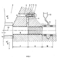
- Fig. 1 is a section through a gear pump is shown, wherein the sectional plane on the one hand along the axis of rotation 13 of a shaft 8 and on the other hand perpendicular to a plane which is spanned by the two shafts of the gear pump extends.
- the second, not visible in Fig. 1 shaft is therefore behind or in front of the illustrated shaft 8.
- a medium M which is for example a polymer or a so-called prepolymer is supplied from a suction side 2 and with a gear 1, ie in the Tooth gaps, transported on a pressure side 3. On the pressure side 3, the pumped medium M is pressed by the intermeshing of the teeth of the two gears from the tooth gaps.
- the gear 1 is on one Shaft 8 mounted or it forms together with the shaft 8 a workpiece.
- Fig. 1 shows that shaft portion which is guided to drive the gear pump to the outside.
- a slide bearing section I in which the shaft 8 is supported or mounted in the housing 9.
- a dynamic seal (sealing section II), which is realized here as a so-called labyrinth seal in the form of a return thread, and a static seal (seal section III), which is here realized with stuffing box packings with a barrier medium.
- the sliding bearings are lubricated with the pumped medium M in the illustrated gear pump.
- conveying medium M penetrates from the pressure side 3, preferably via a bearing lubrication groove 14, into the bearing gap of the slide bearing section I and effects lubrication of the shaft 8.
- the dynamic seal adjoining the slide bearing and the static seal adjoining this prevent the conveying medium M from moving Outside can kick. It is important to ensure that due to a high negative pressure in the transition region between the sliding bearing section I and the sealing section II (dynamic seal) no barrier liquid enters the return channel 4, since then mix the barrier liquid with the pumped medium M and this would be contaminated. At the same time, the pressure in said transition region must not be too high, otherwise the fluid is pressed into the stuffing box packing and degraded there, which can lead to destruction of the static seal.
- FIGS. 2 to 4 show valves 5 according to the invention, which are used in the return duct 4 (FIG. 1).
- the valves are all characterized by a comparison with the known throttle screw improved adjustment.
- a movable part 20, also referred to as a journal is displaceable in a stationary part 21, also referred to as a sleeve, according to arrow 24.
- the sleeve 21 may be configured so that it is a separate part in the Return channel 4 can be inserted or inserted, or the return channel 4 has a corresponding shape in the region of the valve 5 to be realized.
- the advantage of a replaceable sleeve 21 is a rapid adaptability of the valve 5 to changed circumstances, for example, when an optimization to a specific fluid must be made. Corresponding adjustments can also be made on the side of the pin 20.
- the distance in the conical portion of the pin 20 is smaller than the gap width S1 in the cylindrical portion.
- the pressure difference across the valve increases disproportionately (i.e., the importance of the effective length decreases in determining the pressure difference), and the distance (i.e., the gap width S1) now determines the pressure difference across the valve at the third power.
- the function "open / close" becomes active, which follows a strongly nonlinear legislation and the pressure difference correspond strongly increases.
- the function "pressure adjustment” is locally assigned to a pressure adjustment section 22 and the function "open / close” to a closure section 23, whereby the function "open / close” and the function “pressure adjustment” are realized essentially separately from each other.
- the meaning of the phrase “essentially” indicates the fact that there is a certain overlap in that area is, in which it comes to a quasi extension of the effective length. This is indicated by a dashed extension of the pressure adjustment section 22. In proportion to the total length of the pressure adjustment section 22, the overlap is small.
- the overlapping area is, for example, at most 20% of the pressure setting section 22, in particular not more than 10% of the pressure setting section 22.
- a large variety of configurations of the outer shape of the pin 20 and / or the inner shape of the sleeve 21 can now be obtained.
- the embodiments shown in Figs. 3 and 4 are shown. While in the embodiment according to FIG. 3 the gap width S1 is rather constant in the pressure adjustment section 22, the gap width S1 varies in the embodiments according to FIGS. 2 and 4, wherein the variation in the gap width S1 in one case is determined by the outer shape of the journal 20 (FIG. as in Fig. 2) is generated and in the other case by the inner shape of the sleeve 21 (as in Fig. 4). The variation of the gap width S1 by the design of the pin and / or the sleeve can thus be used to obtain targeted adjustment characteristics.
- the adjustment characteristic can be adjusted.
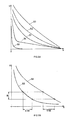
- Fig. 5A shows the adjustment characteristics of a known throttle screw (reference numeral 50) and various valves according to the invention (reference numerals 51, 52, 53 and 54), wherein the abscissa of the adjustment path x of the pin 20 relative to the sleeve 21 is indicated.
- the origin is the fully closed valve.
- the ordinate shows the pressure difference p.
- the extremely steep curve 50 of the adjustment characteristic for gear pumps with the known throttle screw is clearly visible.
- the courses 51 to 54 are significantly flatter, so that a simpler and more precise pressure setting is already apparent from this.
- the curves 51 to 54 are linear within a setting range.
- the linear range corresponds to the pressure adjusting portion 22 (Fig. 2).
- the differences between the progressions 51 to 54 can be achieved, for example, by different gap widths S1 (ie, the gap width S1 is not constant over the effective length x) in the pressure setting section 22 (FIG. 2), as indicated for example in FIGS are.
- the course 54 shows a pronounced linearity, which is a consequence of a constant gap width S1, as is the case, for example, in the embodiment according to FIG.
- Fig. 5B shows two further courses 55 and 56, wherein the course 55 were determined for a low-viscosity and the course 56 for a highly viscous pumped medium using the same valve. Since the same valve was used in the determination of the curves 55 and 56, the pressure to be set p is also in the same operating range B.
- the adjustment path x or the adjustment ranges E55 and E56 resulting from the operating range and the progressions 55 and 56 are due to Different viscosities of the media differently.
- the adjustment ranges E55 and E56 in a first approximation, there is a linear relationship between the adjustment path x and the pressure difference p.
- FIG. 6 shows a further embodiment according to the invention.
- the pumped medium M which has flowed through the bearing gap is directed onto the suction side via a return channel 4 extending at right angles (FIG. 1). the gear pump is returned, wherein the return channel 4 on the one hand as a bore in a housing part 9a and a groove in a housing part 9b is executed.
- a feed unit 60 is provided, by means of which a pin 20 is inserted into the formed as a bore return channel 4.
- FIGS. 2 to 5 in the case of that according to FIG.
- the pin 20 is located in the fully open and in the fully closed position. Overall, the pin 20 can be moved over a maximum length L (maximum displacement x).
- the pointing in the direction of the suction end of the pin can be designed differently.
- the end may be conical - pointed or blunt -, spherical or flat.
- the pressure setting section 23 (Fig. 2) is divided into subsections so as to be able to obtain a further variation in the setting characteristics. Each subsection can be customized to meet specific needs.
- Fig. 7 shows, based on the representation according to FIG. 1, a further embodiment variant for a gear pump.
- the gear pump has a supply channel 15, which connects the pressure side 3 with the region between the sliding bearing and the dynamic seal.
- the valve 5 is not arranged in the return channel 4 but in the feed channel 15.
- the gear pumps are constructed identically, which is why reference is made to the description of FIG. 1 for further explanation.
- valve 5 according to FIG. 7 is in turn used for pressure adjustment or for opening / closing the supply channel 15, the above explanations regarding the valve 5 and the corresponding adjustment characteristics also being valid here.
- FIG. 8 a special feed unit 60 is shown in FIG. 8, which is particularly suitable in connection with the previously described embodiments for setting the adjustment path x in the valves according to the invention.
- the feed unit 60 of the present invention allows a much larger stroke (maximum length L or maximum displacement x), so that pressure adjustment characteristics enabling extremely fine adjustment can be realized.
- the use of the Spindelhubgetriebes 61 allows easier handling during the adjustment process. While in the known throttle screw settings had to be made very close to the rotating drive shaft, the setting in the inventive variant with a Spindelhubgetriebe 61 can be made at right angles to the rotating drive shaft. Thus, the access to the adjustment device is significantly improved and reduces the risk of injury to operating personnel by the rotating drive shaft.
- the feed unit 60 according to the invention is particularly suitable in combination with the valve according to the invention or the various embodiments shown, a combination of the feed unit according to the invention with known valves also leads to those mentioned in connection with the screw jack Benefits. For this reason, the feed unit according to the invention is considered to be independent of the valve according to the invention and therefore deserves protection independent of the valve.
Abstract
Description
Die vorliegende Erfindung betrifft eine Zahnradpumpe nach dem Oberbegriff von Anspruch 1.The present invention relates to a gear pump according to the preamble of
Zahnradpumpen bestehen im Wesentlichen aus einem Gehäuse mit zwei ineinandergreifenden Zahnrädern, die auf Wellen angeordnet sind, wobei mindestens eine der Wellen mit einem Antrieb verbunden ist. Die Wellen werden in Fördermedium-geschmierten Gleitlagern gelagert, welche unmittelbar anschliessend an den Pumpeninnenraum angeordnet sind, wobei das zur Schmierung der Gleitlager verwendete Fördermedium von der Druckseite über den Gleitlagerspalt und einen Rückführungskanal auf die Saugseite der Zahnradpumpe gelangt.Gear pumps consist essentially of a housing with two intermeshing gears, which are arranged on shafts, wherein at least one of the shafts is connected to a drive. The shafts are mounted in fluid-lubricated plain bearings, which are arranged immediately adjacent to the pump interior, wherein the fluid used for lubrication of the sliding bearing passes from the pressure side via the sliding bearing gap and a return channel to the suction side of the gear pump.
Insbesondere bei Zahnradpumpen, die für die Förderung von niederviskosen Polymeren und Prepolymeren verwendet werden und die eine dynamische Dichtung - beispielsweise in der Form einer Labyrinthdichtung (Gewindewellendichtung) - und anschliessender statischen Dichtung - beispielsweise eine Packungsdichtung mit oder ohne Sperrmedium - aufweisen, muss sichergestellt werden, dass vor der dynamischen Wellendichtung immer ein positiver Druck gegenüber der Saugseite vorhanden ist, da sonst - beim Einsatz von einem Sperrmedium - dieses in das Fördermedium gelangen kann, was höchst unerwünscht ist. Der positive Druck ist notwendig, um eine ausreichende Füllung des Dichtspaltes der dynamischen Dichtung zu erhalten. So kann ein Eindringen von Sperrmedium in den Hauptstrom des Fördermediums verhindert werden.In particular, in gear pumps, which are used for the promotion of low-viscosity polymers and prepolymers and having a dynamic seal - for example in the form of a labyrinth seal (threaded shaft seal) - and subsequent static seal - for example, a packing seal with or without barrier medium - must be ensured that before the dynamic shaft seal always a positive pressure against the suction side is present, otherwise - when using a barrier medium - this can get into the fluid, which is highly undesirable. The positive pressure is necessary to obtain a sufficient filling of the sealing gap of the dynamic seal. So can a penetration be prevented by blocking medium in the main flow of the pumped medium.
Auf der anderen Seite sollte der Druck vor der dynamischen Wellendichtung nicht zu gross sein, da sonst Fördermedium durch die dynamische Wellendichtung nach aussen treten kann oder - falls eine statische Dichtung vorhanden ist - das Fördermedium in Kontakt mit dieser Dichtung gelangt, womit mit einer Zerstörung der statischen Dichtung gerechnet werden muss.On the other hand, the pressure before the dynamic shaft seal should not be too large, otherwise pumped medium can pass through the dynamic shaft seal to the outside or - if a static seal is present - the fluid enters into contact with this seal, which with destruction of the static seal must be expected.
Ferner muss gewährleistet sein, dass bei Wartungsarbeiten an der statischen Dichtung der Rückführungskanal geschlossen werden kann. Aus diesem Grund wurde im Rückführungskanal ein Ventil vorgesehen, mit dem ein Eindringen von Luft auf die Saugseite der Zahnradpumpe unterbunden werden kann.It must also be ensured that the return duct can be closed during maintenance work on the static seal. For this reason, a valve was provided in the return channel, with the ingress of air can be suppressed to the suction side of the gear pump.
Das bekannte Ventil eignet sich jedoch nicht, den vorstehend genannten Bedingungen zur Einstellung des Fördermediumsdruckes vor der dynamischen Wellendichtung gerecht zu werden. So ist es aufgrund der Verstellcharakteristik des bekannten Ventils äusserst schwierig, einen Fördermediumsdruck vor der dynamischen Dichtung unter Einhaltung der vorstehend erläuterten Druckbedingungen einstellen zu können, da der Bereich, in dem eine Einstellung vorgenommen werden muss, sehr klein ist.However, the known valve is not suitable to meet the above conditions for adjusting the delivery medium pressure before the dynamic shaft seal. Thus, it is extremely difficult due to the adjustment characteristic of the known valve to be able to set a delivery medium pressure before the dynamic seal in compliance with the above-described pressure conditions, since the area in which an adjustment must be made is very small.
Der vorliegenden Erfindung liegt daher die Aufgabe zugrunde, eine Zahnradpumpe anzugeben, welche die vorstehend genannten Nachteile nicht aufweist.The present invention is therefore based on the object to provide a gear pump, which does not have the disadvantages mentioned above.
Diese Aufgabe ist durch die im kennzeichnenden Teil von Anspruch 1 angegebenen Massnahmen gelöst. Weitere Ausgestaltungen der Erfindung sind in abhängigen Ansprüchen angegeben.This object is achieved by the measures specified in the characterizing part of
Die Erfindung betrifft eine Zahnradpumpe, bestehend aus einem Gehäuse mit mindestens zwei ineinandergreifenden Zahnrädern mit je einer Welle, die in Fördermedium-geschmierten Gleitlagern gelagert sind, wobei ein Fördermedium von einer Saugseite auf eine Druckseite gefördert wird und ein Rückführungskanal vorgesehen ist, der durch das Gleitlager nach aussen fliessendes Fördermedium zur Saugseite zurückführt, und wobei ein Ventil mit einem stationären und einem beweglichen Teil vorgesehen ist. Erfindungsgemäss weist das Ventil eine Einstellcharakteristik auf, die mindestens in einem Bereich in erster Näherung linear verläuft, wobei die Einstellcharakteristik durch einen Druck über dem Ventil in Funktion eines Einstellweges im Ventil definiert ist.The invention relates to a gear pump, comprising a housing with at least two intermeshing gears, each having a shaft which are mounted in fluid-lubricated slide bearings, wherein a fluid is conveyed from a suction side to a pressure side and a return passage is provided by the sliding bearing outwardly flowing fluid returns to the suction side, and wherein a valve is provided with a stationary and a movable part. According to the invention, the valve has an adjustment characteristic which extends linearly in a first approximation in at least one region, the adjustment characteristic being defined by a pressure above the valve as a function of a setting path in the valve.
Damit wird eine wesentliche Verbesserung der Einstellungsmöglichkeit des Druckes im Übergangsbereich zwischen dem Gleitlager und einer dynamischen Dichtung einer nach aussen geführten Antriebswelle erhalten.This results in a substantial improvement in the setting possibility of the pressure in the transitional region between the slide bearing and a dynamic seal of an outwardly guided drive shaft.
Indem das Ventil sowohl zum Öffnen bzw. Schliessen des Rückführungskanals als auch zur Einstellung eines Druckes verwendbar ist, wobei die Funktionen Öffnen/Schliessen und Druckeinstellung im Ventil im Wesentlichen getrennt realisiert sind, ist die Einstellung des Druckes vor dem Ventil, und somit im Übergangsbereich zwischen dem Gleitlager und einer dynamischen Dichtung, wesentlich vereinfacht.By making the valve usable both for opening and closing the return passage and for adjusting a pressure, the functions of opening / closing and pressure adjustment in the valve being realized substantially separately, the adjustment of the pressure in front of the valve, and thus in the transitional region between the plain bearing and a dynamic seal, much easier.
In einer Ausführungsform der vorliegenden Erfindung ist das Ventil im Rückführungskanal enthalten.In one embodiment of the present invention, the valve is contained in the return passage.
Alternativ zur vorstehenden Ausführungsform der Erfindung ist das Ventil in einem Zuführungskanal enthalten, der von der Druckseite in einen von den Zahnrädern aus gesehen nach dem Gleitlager angeordneten Bereich führt.As an alternative to the above embodiment of the invention, the valve is contained in a supply channel, which leads from the pressure side in a region arranged by the gears from the slide bearing area.
In einer Ausführungsform der vorliegenden Erfindung weist das Ventil einen Druckeinstellungsabschnitt auf, der hauptsächlich zur Druckeinstellung dient. Ferner weist das Ventil einen Schliessabschnitt auf, mit dem der das Ventil enthaltende Kanal geöffnet bzw. geschlossen werden kann.In one embodiment of the present invention, the valve has a pressure adjustment section which is primarily for pressure adjustment. Furthermore, the valve has a closing section with which the channel containing the valve can be opened or closed.
In einer weiteren Ausführungsform der vorliegenden Erfindung ist der bewegliche Teil in den stationären Teil einführbar.In a further embodiment of the present invention, the movable part is insertable into the stationary part.
In einer noch weiteren Ausführungsform berühren sich der bewegliche und der stationäre Teil im Schliessabschnitt, wenn der das Ventil enthaltende Kanal geschlossen ist.In yet another embodiment, the movable and stationary parts contact each other in the closing section when the channel containing the valve is closed.
In einer weiteren Ausführungsform der vorliegenden Erfindung weist das Ventil einen Druckeinstellungsabschnitt auf, der hauptsächlich zur Druckeinstellung dient, und einen Schliessabschnitt, in dem der das Ventil enthaltende Kanal geöffnet bzw. geschlossen werden kann, wobei im Druckeinstellungsabschnitt die Einstellcharakteristik in erster Näherung linear verläuft.In another embodiment of the present invention, the valve has a pressure adjusting portion mainly for pressure adjustment and a closing portion in which the passage containing the valve can be opened and closed, and in the pressure adjusting portion, the adjusting characteristic is linearly approximated in the first approximation.
In einer weiteren Ausführungsform der vorliegenden Erfindung ist der stationäre Teil eine austauschbare Hülse.In a further embodiment of the present invention, the stationary part is an exchangeable sleeve.
Eine noch weitere Ausführungsform der vorliegenden Erfindung weist das Ventil die folgenden Abmessungen auf:
Bei einer weiteren Ausführungsform der vorliegenden Erfindung ist der bewegliche Teil lediglich translatorisch verschiebbar.In a further embodiment of the present invention, the movable part is only translationally displaceable.
In einer weiteren Ausführungsform der vorliegenden Erfindung ist ein Spindelhubgetriebe vorgesehen, um den beweglichen Teil translatorisch zu verschieben.In a further embodiment of the present invention, a screw jack is provided to translate the movable member.
In einer noch weiteren Ausführungsform der vorliegenden Erfindung ist der bewegliche Teil am der Saugseite zugewandten Ende kegelförmig, kugelförmig oder flach ausgebildet.In yet another embodiment of the present invention, the movable part at the suction-side end is conical, spherical or flat.
Eine weitere Ausführungsform der vorliegenden Erfindung zeichnet sich dadurch aus, dass der bewegliche Teil einen der folgenden Querschnitte aufweist:
- Polygon, insbesondere ein Dreieck, Viereck oder Sechseck;
- oval;
- rund.
- Polygon, in particular a triangle, quadrangle or hexagon;
- oval;
- round.
Schliesslich besteht eine weitere Ausführungsform der vorliegenden Erfindung darin, dass der Schliessabschnitt in Flussrichtung des Fördermediums nach dem Druckeinstellabschnitt vorgesehen ist.Finally, another embodiment of the present invention is that the closing section is provided in the flow direction of the conveyed medium after the pressure setting section.
Die vorliegende Erfindung wird anhand von Ausführungsbeispielen, die in Figuren gezeigt sind, weiter erläutert. Dabei zeigen:
- Fig. 1
- einen Schnitt entlang einer Drehachse einer nach Aussen geführten Antriebswelle einer Zahnradpumpe in schematischer Darstellung,
- Fig. 2 bis 4
- verschiedene Ausführungsvarianten für ein erfindungsgemässes Ventil,
- Fig. 5A und 5B
- mögliche Verstellcharakteristiken für die verschiedenen Ausführungsvarianten gemäss den Fig. 2 bis 4,
- Fig. 6
- eine weitere Ausführungsvariante für ein erfindungsgemässes Ventil,
- Fig. 7
- einen Schnitt entlang einer Drehachse einer nach Aussen geführten Antriebswelle einer weiteren Ausführungsform einer Zahnradpumpe in schematischer Darstellung und
- Fig. 8
- ein erfindungsgemässes Ventil mit einem translatorisch verschiebbaren beweglichen Teil.
- Fig. 1
- a section along a rotation axis of an outwardly guided drive shaft of a gear pump in a schematic representation,
- Fig. 2 to 4
- various embodiments for a valve according to the invention,
- Figs. 5A and 5B
- possible Verstellcharakteristiken for the various embodiments according to FIGS. 2 to 4,
- Fig. 6
- a further embodiment variant for a valve according to the invention,
- Fig. 7
- a section along an axis of rotation of an outwardly guided drive shaft of another embodiment of a gear pump in a schematic representation and
- Fig. 8
- a valve according to the invention with a translationally movable part.
In Fig. 1 ist ein Schnitt durch eine Zahnradpumpe dargestellt, wobei die Schnittebene einerseits entlang der Drehachse 13 einer Welle 8 und anderseits senkrecht auf eine Ebene, die von den beiden Wellen der Zahnradpumpe aufgespannt wird, verläuft. Die zweite, in Fig. 1 nicht ersichtliche Welle liegt demzufolge hinter oder vor der dargestellten Welle 8. Ein Fördermedium M, das beispielsweise ein Polymer oder ein so genanntes Prepolymer ist, wird von einer Saugseite 2 zugeführt und mit einem Zahnrad 1, d.h. in den Zahnlücken, auf eine Druckseite 3 befördert. Auf der Druckseite 3 wird das Fördermedium M durch das Ineinandergreifen der Zähne der beiden Zahnräder aus den Zahnlücken gepresst. Das Zahnrad 1 ist auf einer Welle 8 montiert oder es bildet zusammen mit der Welle 8 ein Werkstück.In Fig. 1 is a section through a gear pump is shown, wherein the sectional plane on the one hand along the axis of
Fig. 1 zeigt denjenigen Wellenabschnitt, der zum Antrieb der Zahnradpumpe nach Aussen geführt ist. Ausgehend vom Zahnrad 1 folgt zunächst ein Gleitlagerabschnitt I, in dem die Welle 8 im Gehäuse 9 abgestützt bzw. gelagert ist. Anschliessend an den Gleitlagerabschnitt I folgt eine dynamische Dichtung (Dichtungsabschnitt II), die hier als so genannte Labyrinthdichtung in Form eines Rückfördergewindes realisiert ist, und eine statische Dichtung (Dichtungsabschnitt III), die hier mit Stopfbüchsenpackungen mit einem Sperrmedium realisiert ist.Fig. 1 shows that shaft portion which is guided to drive the gear pump to the outside. Starting from the
Die Gleitlager werden bei der dargestellten Zahnradpumpe mit dem Fördermedium M geschmiert. So dringt Fördermedium M von der Druckseite 3, vorzugsweise über eine Lagerschmiernut 14, in den Lagerspalt des Gleitlagerabschnittes I ein und bewirkt eine Schmierung der Welle 8. Die an das Gleitlager anschliessende dynamische Dichtung und die an diese anschliessende statische Dichtung verhindern, dass Fördermedium M nach Aussen treten kann. Es ist darauf zu achten, dass aufgrund eines hohen Unterdruckes im Übergangsbereich zwischen dem Gleitlagerabschnitt I und dem Dichtungsabschnitt II (dynamischen Dichtung) kein Sperrflüssigkeit in den Rückführungskanal 4 gelangt, da sich dann die Sperrflüssigkeit mit dem Fördermedium M vermischen und dieses verunreinigt würde. Gleichzeitig darf der Druck im besagten Übergangsbereich nicht zu hoch sein, da ansonsten das Fördermedium in die Stopfbüchsenpackung gepresst wird und dort degradiert, was zu einer Zerstörung der statischen Dichtung führen kann.The sliding bearings are lubricated with the pumped medium M in the illustrated gear pump. Thus, conveying medium M penetrates from the
Wie eingangs bereits erläutert worden ist, ist die Verwendung einer Drosselschraube im Rückführungskanal 4 bereits bekannt. Diese Drosselschraube wurde in erster Linie zum vollständigen Verschliessen des Rückführungskanals 4 verwendet, wie dies zum Beispiel bei einer vorübergehenden Stilllegung der Zahnradpumpe jeweils gemacht werden muss. Zudem wurde jeweils versucht, während dem Betrieb der Zahnradpumpe die vorstehend erläuterten Bedingungen in Bezug auf die Druckverhältnisse nach dem Gleitlagerabschnitt I zu erfüllen. Dies ist mit einer einfachen Drosselschraube, wie sie in bekannter Weise zum Einsatz gekommen ist, sehr schwierig zu bewerkstelligen.As has already been explained, the use of a throttle screw in the
In den Fig. 2 bis 4 sind erfindungsgemässe Ventile 5 dargestellt, die im Rückführungskanal 4 (Fig. 1) zum Einsatz kommen. Die Ventile zeichnen sich alle durch eine gegenüber der bekannten Drosselschraube verbesserte Verstellcharakteristik aus.FIGS. 2 to 4
Anhand der Ausführungsvariante gemäss Fig. 2, in der ein Ventil 5 in einem Schnitt dargestellt ist, wird das erfindungsgemässe Prinzip erläutert. Ein beweglicher Teil 20, auch etwa als Zapfen bezeichnet, ist in einem stationären Teil 21, auch etwa als Hülse bezeichnet, gemäss Pfeil 24 verschiebbar. Dabei kann die Hülse 21 so ausgestaltet sein, dass sie als separater Teil in den Rückführungskanal 4 eingelassen bzw. eingeschoben werden kann, oder der Rückführungskanal 4 weist eine entsprechende Form im Bereich des zu realisierenden Ventils 5 auf. Der Vorteil einer austauschbaren Hülse 21 liegt in einer raschen Anpassbarkeit des Ventils 5 an geänderte Umstände, so zum Beispiel, wenn eine Optimierung auf ein bestimmtes Fördermedium vorgenommen werden muss. Entsprechende Anpassungen können auch auf der Seite des Zapfens 20 vorgenommen werden.Based on the embodiment according to FIG. 2, in which a
Das erfindungsgemässe Ventil 5 zeichnet sich nun insbesondere dadurch aus, dass die beiden vom Ventil zu erfüllende Funktionen, nämlich das Öffnen/Schliessen des Rückführungskanals 4 als auch die Druckeinstellung im Übergangsbereich vom Gleitlagerabschnitt I zum dynamischen Dichtungsabschnitt II (Fig. 1), im Wesentlichen getrennt realisiert sind. Dies bedeutet nicht, dass keine Überlagerungen zwischen den Funktionen möglich sind, dass jedoch eine weitgehende Unabhängigkeit zwischen den Funktionen vorhanden ist. Im Folgenden werden die diesbezüglichen Zusammenhänge und die Wirkungsweise des Ventils erläutert:
- Bei einem vollständig geöffneten Ventil 5 sind die Druckverhältnisse in Flussrichtung vor und nach
dem Ventil 5 im Wesentlichen identisch. Durch das Einführen des Zapfens 20 indie Hülse 21 wird die Querschnittfläche für das Fördermedium M zunächst verringert. Damit erfolgt eine erste Zunahme der Druckdifferenz überdas Ventil 5. In vielen Anwendungen ist dies die Ausgangslage, d.h. die Position mit der kleinstmöglichen Druckdifferenz.
- In a fully
open valve 5, the pressure ratios in the flow direction before and after thevalve 5 are substantially identical. By inserting thepin 20 into thesleeve 21, the cross-sectional area for the pumped medium M is initially reduced. This results in a first increase in the pressure difference across thevalve 5. In This is the starting position for many applications, ie the position with the smallest possible pressure difference.
Mit dem weiteren Eindringen des Zapfens 20 in die Hülse 21 wird nicht mehr die Querschnittsfläche verändert - d.h. eine Spaltbreite S1, die zwischen dem Zapfen 20 und der Hülse 21 vorhanden ist, bleibt im Wesentlichen unverändert - sondern es ist nun allein die Eindringtiefe (im Folgenden auch wirksame Länge oder Einstellweg genannt) des Zapfens 20 in die Hülse 21, welche zu einer Druckdifferenzänderung über dem Ventil 5 führt. Damit wurde erstmals eine zumindest bereichsweise, in erster Näherung lineare Einstellcharakteristik erhalten, was eine Einstellung eines optimalen Druckes im Übergangsbereich zwischen Gleitlagerabschnitt I und dynamischer Dichtungsabschnitt II wesentlich vereinfacht und eine genaue Einstellung erleichtert.With the further penetration of the
Zur weiteren Erläuterung der Erfindung wurden Berechnungen angestellt, deren Resultat in der folgenden Formel zusammengefasst werden kann, die zur Vereinfachung auf einigen Modellannahmen beruht: 
wobei
- Δp
- resultierende Druckdifferenz über dem Ventil
- Q
- Durchsatz
- η
- Viskosität
- x
- wirksame Länge oder Einstellweg
- D
- Zapfendurchmesser
- S1
- Spaltbreite
in which
- Ap
- resulting pressure difference across the valve
- Q
- throughput
- η
- viscosity
- x
- effective length or adjustment path
- D
- Journal diameter
- S1
- gap width
Bei der bekannten Drosselschraube, für die die vorstehenden Berechnungen ebenfalls gültig sind, wird primär der kurze Ringspalt, welcher durch die Spalthöhe S1 charakterisiert werden kann, am kurzen Ende verringert. Diese Verringerung fliesst in der dritten Potenz in die Berechnungen ein, was zu einer sehr grossen Druckänderung bei geringer Änderung der Spaltbreite S1 führt.In the known throttle screw, for which the above calculations are also valid, primarily the short annular gap, which can be characterized by the gap height S1, is reduced at the short end. This reduction is included in the calculations in the third power, which leads to a very large change in pressure with little change in the gap width S1.
Demgegenüber wird bei der erfindungsgemässen Vorrichtung mit dem weiteren Vorschieben des Zapfens 20 in die Hülse 21 eine beinahe linear ansteigende Druckdifferenz erreicht, weil - wie mit vorstehender Formel erklärt werden kann - die Spaltbreite S1 nur gering verändert wird und im wesentlichen nur der Einstellweg x verändert wird. Der in erster Näherung lineare Zusammenhang von Einstellweg und Druckdifferenz bleibt unter den genannten Voraussetzungen gültig. Eine Änderung tritt in derjenigen Position ein, die in Fig. 2 dargestellt ist. In dieser Position wird die wirksame Länge x (Einstellweg) quasi verlängert, ohne dass der Zapfen 20 weiter in die Hülse 21 geschoben wird. Der kegelförmige Zapfen 20 und die kegelförmige Hülse 21 weisen nämlich in dieser Stellung einen Abstand zueinander auf, welcher der Spaltbreite S1 im zylinderförmigen Bereich des Zapfens 20 bzw. der Hülse 21 entspricht. Damit ist die wirksame Länge (Einstellweg x), welche von Fördermedium M im Ventil mit gleicher Spaltbreite S1 durchflossen wird, durch die entsprechenden Abmessungen im kegelförmigen Bereich des Zapfens verlängert. Als Resultat davon steigt die Druckdifferenz proportional zu dieser neuen wirksamen Länge an, was einen ersten überproportionalen Anstieg in der Druckdifferenz zur Folge hat.In contrast, in the inventive device with the further advancement of the
Wird nun der Zapfen noch weiter in die Hülse geschoben, so wird der Abstand im kegelförmigen Bereich des Zapfens 20 kleiner als die Spaltbreite S1 im zylinderförmigen Abschnitt. Damit steigt die Druckdifferenz über dem Ventil überproportional an (d.h. die Bedeutung der wirksamen Länge nimmt bei der Bestimmung der Druckdifferenz ab), und der Abstand (d.h. die Spaltbreite S1) bestimmt nun in der dritten Potenz die Druckdifferenz über dem Ventil. Mit anderen Worten wird nun die Funktion "Öffnen/Schliessen" aktiv, die einer stark nichtlinearen Gesetzgebung folgt und die Druckdifferenz entsprechen stark ansteigen lässt.If now the pin pushed further into the sleeve, the distance in the conical portion of the
Aus den vorstehenden Ausführungen kann die Realisation der beiden Funktionen "Öffnen/Schliessen" und "Druckeinstellung" innerhalb des Ventils 5 lokalisiert werden: So wird die Funktion "Druckeinstellung" einem Druckeinstellungsabschnitt 22 und die Funktion "Öffnen/Schliessen" einem Schliessabschnitt 23 örtlich zugewiesen, womit die Funktion "Öffnen/Schliessen" und die Funktion "Druckeinstellung" im Wesentlichen getrennt voneinander realisiert sind. Die Bedeutung der Redewendung "im Wesentlichen" weist dabei auf den Umstand hin, dass eine gewisse Überlappung in demjenigen Bereich vorhanden ist, in dem es zu einer quasi Verlängerung der wirksamen Länge kommt. Dies wird durch eine strichlinierten Verlängerung des Druckeinstellungsabschnittes 22 angedeutet. Im Verhältnis zur Gesamtlänge des Druckeinstellungsabschnittes 22 ist die Überlappung klein. Der Überlappungsbereich beträgt beispielsweise maximal 20% des Druckeinstellungsabschnittes 22, insbesondere maximal 10% des Druckeinstellungsabschnittes 22.From the foregoing, the realization of the two functions "open / close" and "pressure adjustment" can be located within the valve 5: Thus, the function "pressure adjustment" is locally assigned to a
Basierend auf den vorstehenden eher allgemeinen Ausführungen lassen sich nun eine grosse Vielfalt von Ausgestaltungen der äusseren Form des Zapfens 20 und/oder der inneren Form der Hülse 21 erhalten. Als Beispiele sind die Ausführungsvarianten, die in den Fig. 3 und 4 gezeigt sind. Während bei der Ausführungsform gemäss Fig. 3 die Spaltbreite S1 eher konstant im Druckeinstellungsabschnitt 22 ist, variiert die Spaltbreite S1 in den Ausführungsformen gemäss Fig. 2 und 4, wobei die Variation in der Spaltbreite S1 im einen Fall durch die äussere Form des Zapfens 20 (wie in Fig. 2) erzeugt wird und im anderen Fall durch die innere Form der Hülse 21 (wie in Fig. 4). Die Variation der Spaltbreite S1 durch die Formgestaltung des Zapfens und/oder der Hülse kann somit verwendet werden, um gezielte Einstellungscharakteristiken zu erhalten.Based on the above rather general embodiments, a large variety of configurations of the outer shape of the
Es hat sich gezeigt, dass die Grössenverhältnisse wie folgt einzustellen sind:
Es wird darauf hingewiesen, dass insbesondere mit einer Variation der Spaltbreite S1 über den Einstellungsabschnitt 22 die Einstellungscharakteristik angepasst werden kann.It should be noted that, in particular with a variation of the gap width S1 via the
Fig. 5A zeigt die Einstellungscharakteristiken einer bekannten Drosselschraube (Bezugszeichen 50) und von verschiedenen erfindungsgemässen Ventilen (Bezugszeichen 51, 52, 53 und 54), wobei auf der Abszisse der Einstellweg x des Zapfens 20 gegenüber der Hülse 21 angegeben ist. Hierbei stellt der Ursprung das vollständig geschlossene Ventil dar. Auf der Ordinate ist die Druckdifferenz p eingetragen.Fig. 5A shows the adjustment characteristics of a known throttle screw (reference numeral 50) and various valves according to the invention (
In Fig. 5A ist der äusserst steile Verlauf 50 der Einstellcharakteristik für Zahnradpumpen mit der bekannten Drosselschraube deutlich erkennbar. Demgegenüber sind die Verläufe 51 bis 54 deutlich flacher ausgebildet, so dass eine einfachere und präzisere Druckeinstellung bereits hieraus erkennbar ist. In erster Näherung sind die Verläufe 51 bis 54 innerhalb eines Einstellbereiches linear. Der lineare Bereich entspricht dem Druckeinstellabschnitt 22 (Fig. 2). Die Unterschiede zwischen den Verläufen 51 bis 54 lassen sich beispielsweise durch unterschiedliche Spaltbreiten S1 (d.h. die Spaltbreite S1 ist nicht konstant über die wirksame Länge x) im Druckeinstellabschnitt 22 (Fig. 2) erwirken, wie sie beispielsweise in den Fig. 2 bis 4 angedeutet sind. Dabei zeigt insbesondere der Verlauf 54 eine ausgeprägte Linearität, was eine Folge einer konstanten Spaltbreite S1 ist, wie dies beispielsweise auch bei der Ausführungsform gemäss Fig. 3 der Fall ist.In Fig. 5A, the extremely
Fig. 5B zeigt zwei weitere Verläufe 55 und 56, wobei der Verlauf 55 für ein niederviskoses und der Verlauf 56 für ein hochviskoses Fördermedium bei Verwendung desselben Ventils ermittelt wurden. Da bei der Bestimmung der Verläufe 55 und 56 das gleiche Ventil verwendet wurde, ist auch der einzustellende Druck p im gleichen Betriebsbereich B. Der Einstellweg x bzw. die sich aus dem Betriebsbereich und den Verläufen 55 und 56 ergebenden Einstellungsbereiche E55 und E56 sind aufgrund der unterschiedlichen Viskositäten der Fördermedien unterschiedlich. Wie aus den Verläufen 55 und 56 deutlich ersichtlich ist, besteht in den Einstellungsbereichen E55 und E56 in erster Näherung ein linearer Zusammenhang zwischen dem Einstellweg x und der Druckdifferenz p. Während beim Verlauf 56 im Einstellungsbereich E56 sogar ein linearer Zusammenhang zwischen dem Einstellweg x und der Druckdifferenz p besteht, weist der Verlauf 56 aufgrund der leichten Krümmung im Einstellbereich erst in erster Näherung ein linearer Zusammenhang auf. Zur Verdeutlichung dieses Sachverhaltes wurden in Fig. 5B die beiden Endpunkte im Einstellbereich E55 durch eine strich-linierte Linie verbunden.Fig. 5B shows two
In Fig. 6 ist eine weitere erfindungsgemässe Ausführungsform dargestellt. Das durch den Lagerspalt geströmte Fördermedium M wird über einen rechtwinklig verlaufenden Rückführungskanal 4 auf die Saugseite (Fig. 1) der Zahnradpumpe zurückgeleitet, wobei der Rückführungskanal 4 einerseits als Bohrung in einem Gehäuseteil 9a und als Nut in einem Gehäuseteil 9b ausgeführt ist. Im Eckpunkt des rechtwinkligen Verlaufes des Rückführungskanals 4 ist eine Vorschubeinheit 60 vorgesehen, mittels der ein Zapfen 20 in den als Bohrung ausgebildeten Rückführungskanal 4 eingeschoben wird. Im Unterschied zu den Ausführungsformen gemäss den Fig. 2 bis 5 ist bei derjenigen gemäss Fig. 6 die Anordnung der zwei Funktionen "Öffnen/Schliessen" und "Druckeinstellung" umgekehrt: Die Druckeinstellung erfolgt auf der Seite des Endes des Zapfes 20 und die Funktion "Öffnen/Schliessen" auf der Seite der Vorschubeinheit 60. Damit lassen sich auch bestehende Zahnradpumpe auf einfache Art und Weise mit einem erfindungsgemässen Ventil ausstatten, ohne dass das Pumpengehäuse abgeändert werden muss.FIG. 6 shows a further embodiment according to the invention. The pumped medium M which has flowed through the bearing gap is directed onto the suction side via a
Zu beachten ist, dass in Fig. 6 der Zapfen 20 in der vollständig geöffneten als auch in der vollständig geschlossenen Stellung eingezeichnet ist. Insgesamt kann der Zapfen 20 über eine maximale Länge L (maximaler Verstellweg x) verschoben werden.It should be noted that in Fig. 6, the
Bei allen Ausführungsvarianten des Zapfens als auch der Hülse ist denkbar, einen von einer Rotationssymmetrie abweichenden Querschnitt vorzusehen. So ist insbesondere denkbar, dass der Zapfen und/oder die Hülse einen der folgenden Querschnitte aufweist:
- Polygon, insbesondere ein Dreieck, Viereck oder Sechseck;
- oval;
- rund.
- Polygon, in particular a triangle, quadrangle or hexagon;
- oval;
- round.
Ferner kann auch das in Richtung Saugseite zeigende Ende des Zapfens unterschiedlich ausgestaltet sein. Insbesondere kann das Ende kegelförmig - und zwar spitz oder stumpf -, kugelförmig oder flach ausgeführt sein.Furthermore, the pointing in the direction of the suction end of the pin can be designed differently. In particular, the end may be conical - pointed or blunt -, spherical or flat.
Schliesslich ist auch denkbar, dass der Druckeinstellabschnitt 23 (Fig. 2) in Unterabschnitte eingeteilt ist, um so eine weitere Variation bei den Einstellcharakteristiken erhalten zu können. Jeder Unterabschnitt kann individuell an bestimmte Bedürfnisse angepasst werden.Finally, it is also conceivable that the pressure setting section 23 (Fig. 2) is divided into subsections so as to be able to obtain a further variation in the setting characteristics. Each subsection can be customized to meet specific needs.
Fig. 7 zeigt in Anlehnung an die Darstellungsart gemäss Fig. 1 eine weitere Ausführungsvariante für eine Zahnradpumpe. Im Unterschied zu derjenigen gemäss Fig. 1 weist die Zahnradpumpe ein Zuführungskanal 15 auf, der die Druckseite 3 mit dem Bereich zwischen dem Gleitlager und der dynamischen Dichtung verbindet. Des Weiteren ist das Ventil 5 nicht im Rückführungskanal 4 sondern im Zuführungskanal 15 angeordnet. Im Übrigen sind die Zahnradpumpen identisch aufgebaut, weshalb für weitere Erläuterungen auf die Beschreibung der Fig. 1 verwiesen wird.Fig. 7 shows, based on the representation according to FIG. 1, a further embodiment variant for a gear pump. In contrast to that according to FIG. 1, the gear pump has a
Das Ventil 5 gemäss Fig. 7 wird wiederum zur Druckeinstellung bzw. zum Öffnen/Schliessen des Zuführungskanals 15 verwendet, wobei die vorstehenden Ausführungen zum Ventil 5 und der entsprechenden Einstellungscharakteristiken auch hier ihre Gültigkeit haben.The
Schliesslich ist in Fig. 8 eine besondere Vorschubeinheit 60 dargestellt, die sich vorzüglich in Verbindung mit den vorstehend beschriebenen Ausführungsvarianten zur Einstellung des Verstellweges x bei den erfindungsgemässen Ventilen eignet.Finally, a
Die eingangs beschriebenen bekannten Drosselschrauben führen während dem Verschieben des Zapfens 20 eine Rotation um die eigene Achse aus. Damit werden die Dichtungen, welche dafür sorgen, dass kein Fördermedium M in Richtung Vorschubeinheit fliesst, nicht nur durch die eigentliche Vorschubbewegung beansprucht, sondern zusätzlich auch durch die Rotation um die eigene Achse. Während der Druckeinstellung und insbesondere auch bei einem Schliessen bzw. Öffnen des Rückführungskanals werden diese Dichtungen so stark beansprucht, dass ihre Lebenserwartung empfindlich eingeschränkt ist.The well-known throttle screws described above perform during the displacement of the pin 20 a rotation about its own axis. Thus, the seals, which ensure that no fluid flows M in the direction of feed unit, not only claimed by the actual feed motion, but also by the rotation about its own axis. During the pressure setting and in particular also when the return channel is closed or opened, these seals are stressed so heavily that their life expectancy is severely restricted.
Ein weiterer erfindungsgemässer Aspekt führt zu einer wesentlichen Verbesserung dieses Problems. So wird durch die Verwendung eines Spindelhubgetriebes 61 es ermöglicht, dass eine translatorische Bewegung erhalten werden kann. Mithin werden die Dichtungen 63 nicht mehr durch eine Eigenrotation des Zapfens 20 beansprucht, sondern lediglich noch durch die eigentliche translatorische Bewegung, die zur Einstellung des Druckes oder zum Öffnen/Schliessen des Ventils notwendig ist. Der Gleitweg der Dichtung wird somit reduziert.Another aspect of the invention leads to a substantial improvement of this problem. Thus, the use of a
Ferner ermöglicht die erfindungsgemässe Vorschubeinheit 60 einen wesentlich grösseren Hub (maximale Länge L bzw. maximale Verstellweg x), so dass Druckeinstellungscharakteristiken realisiert werden können, die eine überaus feine Einstellung ermöglichen.Further, the
Schliesslich erlaubt der Einsatz des Spindelhubgetriebes 61 eine einfachere Handhabung während dem Einstellungsvorgang. Während bei der bekannten Drosselschraube die Einstellungen sehr nahe an der rotierenden Antriebswelle vorgenommen werden mussten, kann die Einstellung bei der erfindungsgemässen Ausführungsvariante mit einem Spindelhubgetriebe 61 rechtwinklig von der rotierenden Antriebswelle vorgenommen werden. Damit ist der Zugang zur Einstellvorrichtung wesentlich verbessert und die Gefahr einer Verletzung von Bedienpersonal durch die rotierende Antriebswelle vermindert.Finally, the use of the
Obwohl sich die erfindungsgemässe Vorschubeinheit 60 besonders in Kombination mit dem erfindungsgemässen Ventil bzw. den verschiedenen dargestellten Ausführungsvarianten eignet, führt auch eine Kombination der erfindungsgemässen Vorschubeinheit mit bekannten Ventilen zu den im Zusammenhang mit dem Spindelhubgetriebe erwähnten Vorteilen. Aus diesem Grund ist die erfindungsgemässe Vorschubeinheit als unabhängig vom erfindungsgemässen Ventil zu betrachten und verdient daher einen vom Ventil unabhängigen Schutz.Although the
Claims (15)
Priority Applications (5)
| Application Number | Priority Date | Filing Date | Title |
|---|---|---|---|
| EP06113845A EP1855007A1 (en) | 2006-05-12 | 2006-05-12 | Gear pump |
| EP07729112A EP2018479A1 (en) | 2006-05-12 | 2007-05-14 | Gearwheel pump |
| PCT/EP2007/054660 WO2007131994A1 (en) | 2006-05-12 | 2007-05-14 | Gearwheel pump |
| JP2009508394A JP5027216B2 (en) | 2006-05-12 | 2007-05-14 | Gear pump |
| US12/294,330 US8038422B2 (en) | 2006-05-12 | 2007-05-14 | Gear pump with a valve arranged between a suction side and a pressure side of the gear pump |
Applications Claiming Priority (1)
| Application Number | Priority Date | Filing Date | Title |
|---|---|---|---|
| EP06113845A EP1855007A1 (en) | 2006-05-12 | 2006-05-12 | Gear pump |
Publications (1)
| Publication Number | Publication Date |
|---|---|
| EP1855007A1 true EP1855007A1 (en) | 2007-11-14 |
Family
ID=37054810
Family Applications (2)
| Application Number | Title | Priority Date | Filing Date |
|---|---|---|---|
| EP06113845A Withdrawn EP1855007A1 (en) | 2006-05-12 | 2006-05-12 | Gear pump |
| EP07729112A Withdrawn EP2018479A1 (en) | 2006-05-12 | 2007-05-14 | Gearwheel pump |
Family Applications After (1)
| Application Number | Title | Priority Date | Filing Date |
|---|---|---|---|
| EP07729112A Withdrawn EP2018479A1 (en) | 2006-05-12 | 2007-05-14 | Gearwheel pump |
Country Status (4)
| Country | Link |
|---|---|
| US (1) | US8038422B2 (en) |
| EP (2) | EP1855007A1 (en) |
| JP (1) | JP5027216B2 (en) |
| WO (1) | WO2007131994A1 (en) |
Cited By (1)
| Publication number | Priority date | Publication date | Assignee | Title |
|---|---|---|---|---|
| EP3964689A1 (en) * | 2020-09-08 | 2022-03-09 | Eaton Intelligent Power Limited | Gear pump with self-lubricating bearings |
Families Citing this family (2)
| Publication number | Priority date | Publication date | Assignee | Title |
|---|---|---|---|---|
| EP2588756B1 (en) | 2010-07-02 | 2018-05-02 | Oerlikon Textile GmbH & Co. KG | Gear pump |
| WO2017009994A1 (en) * | 2015-07-16 | 2017-01-19 | 株式会社Ihi | Triple gear pump and fluid supplying device |
Citations (5)
| Publication number | Priority date | Publication date | Assignee | Title |
|---|---|---|---|---|
| EP0669465A2 (en) * | 1995-05-24 | 1995-08-30 | Maag Pump Systems AG | Bearing arrangement for a viscous fluid pump |
| JPH08303356A (en) * | 1995-04-28 | 1996-11-19 | Shimadzu Corp | Gear pump |
| JPH0914154A (en) * | 1995-06-26 | 1997-01-14 | Shimadzu Corp | Gear pump or motor |
| JPH10331779A (en) * | 1997-05-28 | 1998-12-15 | Japan Steel Works Ltd:The | Gear pump for polymer |
| US20040109780A1 (en) * | 2001-12-12 | 2004-06-10 | Georg Gillert | Feed pump for fluidic media |
Family Cites Families (7)
| Publication number | Priority date | Publication date | Assignee | Title |
|---|---|---|---|---|
| DE644570C (en) * | 1934-02-27 | 1937-05-07 | Fritz Egersdoerfer | Fast running gear pump |
| US3703273A (en) * | 1970-08-24 | 1972-11-21 | Kieley & Mueller | Low loss innervalve assembly |
| JPS6435185A (en) * | 1987-07-30 | 1989-02-06 | Fuji Photo Film Co Ltd | Flow control valve |
| GB2208421B (en) * | 1987-07-30 | 1991-09-04 | Kent Process Control Ltd | Flow control valve |
| DE4331417A1 (en) * | 1993-09-15 | 1995-03-16 | Wabco Vermoegensverwaltung | Valve |
| JPH09144668A (en) * | 1995-11-27 | 1997-06-03 | Shimadzu Corp | Gear pump |
| DE10239558B4 (en) * | 2002-08-28 | 2005-03-17 | SCHWäBISCHE HüTTENWERKE GMBH | External gear pump with pressurized fluid precharge |
-
2006
- 2006-05-12 EP EP06113845A patent/EP1855007A1/en not_active Withdrawn
-
2007
- 2007-05-14 EP EP07729112A patent/EP2018479A1/en not_active Withdrawn
- 2007-05-14 US US12/294,330 patent/US8038422B2/en not_active Expired - Fee Related
- 2007-05-14 JP JP2009508394A patent/JP5027216B2/en not_active Expired - Fee Related
- 2007-05-14 WO PCT/EP2007/054660 patent/WO2007131994A1/en active Application Filing
Patent Citations (5)
| Publication number | Priority date | Publication date | Assignee | Title |
|---|---|---|---|---|
| JPH08303356A (en) * | 1995-04-28 | 1996-11-19 | Shimadzu Corp | Gear pump |
| EP0669465A2 (en) * | 1995-05-24 | 1995-08-30 | Maag Pump Systems AG | Bearing arrangement for a viscous fluid pump |
| JPH0914154A (en) * | 1995-06-26 | 1997-01-14 | Shimadzu Corp | Gear pump or motor |
| JPH10331779A (en) * | 1997-05-28 | 1998-12-15 | Japan Steel Works Ltd:The | Gear pump for polymer |
| US20040109780A1 (en) * | 2001-12-12 | 2004-06-10 | Georg Gillert | Feed pump for fluidic media |
Cited By (2)
| Publication number | Priority date | Publication date | Assignee | Title |
|---|---|---|---|---|
| EP3964689A1 (en) * | 2020-09-08 | 2022-03-09 | Eaton Intelligent Power Limited | Gear pump with self-lubricating bearings |
| US11703050B2 (en) | 2020-09-08 | 2023-07-18 | Eaton Intelligent Power Limited | Gear pump with self-lubricating bearings |
Also Published As
| Publication number | Publication date |
|---|---|
| WO2007131994A1 (en) | 2007-11-22 |
| EP2018479A1 (en) | 2009-01-28 |
| US20090169408A1 (en) | 2009-07-02 |
| JP2009536992A (en) | 2009-10-22 |
| US8038422B2 (en) | 2011-10-18 |
| JP5027216B2 (en) | 2012-09-19 |
Similar Documents
| Publication | Publication Date | Title |
|---|---|---|
| DE3333647C2 (en) | Lubricant pump for generating pressure in an internal combustion engine lubricated by pressure circulation | |
| EP2683955B1 (en) | Plain bearing half liner | |
| DE1528951B2 (en) | ||
| DE102005041579B4 (en) | Internal gear pump with filling piece | |
| EP0619430A1 (en) | Internal gear pump for high rotary speed range | |
| DE102011101648B4 (en) | Screw machine, in particular screw pump | |
| DE10025723A1 (en) | Regulated pump | |
| EP1855007A1 (en) | Gear pump | |
| DE102006018285B4 (en) | Pump, in particular gear pump or vane pump | |
| DE202016106107U1 (en) | Rotary lobe pump with sealing chamber seal | |
| EP1855008B1 (en) | Gear pump | |
| WO2004033187A1 (en) | Extruder/gear pump assembly | |
| EP1219841B1 (en) | Slide bearing,especially for a gear pump | |
| EP1328730B1 (en) | Internal geared wheel pump without a filler piece | |
| DE102012209775A1 (en) | Gear wheel machine e.g. pump and electromotor, has wheels teeth comprising clamping surface arranged such that clamping surface does not contact force transferring tooth flank of gear wheels in all rotational positions of machine | |
| DE102004021216B4 (en) | High-pressure internal gear machine with multiple hydrostatic bearings per ring gear | |
| EP0674746B1 (en) | Swash plate machine | |
| DE102010005984B4 (en) | Usually oil pump | |
| DE102007018692A1 (en) | Controllable pump e.g. lubricant pump, for internal combustion engine, has adjusting ring surrounding rotor, and hydraulic connection provided between chamber and effective surface acting on ring in direction | |
| EP3913187B1 (en) | Screw spindle pump | |
| DE4313442A1 (en) | Fluid pump | |
| DE3624382A1 (en) | Eccentric gate valve pump, especially for the delivery of lubricants for drives | |
| EP1722104B1 (en) | Rotor pair for a screw compressor | |
| DE102023109356A1 (en) | Drive unit for a motor metering pump | |
| EP4043727A1 (en) | Control valve with optimized cross section |
Legal Events
| Date | Code | Title | Description |
|---|---|---|---|
| PUAI | Public reference made under article 153(3) epc to a published international application that has entered the european phase |
Free format text: ORIGINAL CODE: 0009012 |
|
| AK | Designated contracting states |
Kind code of ref document: A1 Designated state(s): AT BE BG CH CY CZ DE DK EE ES FI FR GB GR HU IE IS IT LI LT LU LV MC NL PL PT RO SE SI SK TR |
|
| AX | Request for extension of the european patent |
Extension state: AL BA HR MK YU |
|
| AKX | Designation fees paid | ||
| REG | Reference to a national code |
Ref country code: DE Ref legal event code: 8566 |
|
| STAA | Information on the status of an ep patent application or granted ep patent |
Free format text: STATUS: THE APPLICATION IS DEEMED TO BE WITHDRAWN |
|
| 18D | Application deemed to be withdrawn |
Effective date: 20080515 |