EP1854680A2 - Compact gas generator for electric pyrotechnic systems and a method of producing it - Google Patents
Compact gas generator for electric pyrotechnic systems and a method of producing it Download PDFInfo
- Publication number
- EP1854680A2 EP1854680A2 EP07466010A EP07466010A EP1854680A2 EP 1854680 A2 EP1854680 A2 EP 1854680A2 EP 07466010 A EP07466010 A EP 07466010A EP 07466010 A EP07466010 A EP 07466010A EP 1854680 A2 EP1854680 A2 EP 1854680A2
- Authority
- EP
- European Patent Office
- Prior art keywords
- gas generator
- compact gas
- outer cover
- contacts
- pyrotechnic systems
- Prior art date
- Legal status (The legal status is an assumption and is not a legal conclusion. Google has not performed a legal analysis and makes no representation as to the accuracy of the status listed.)
- Withdrawn
Links
- 238000000034 method Methods 0.000 title claims abstract description 11
- 239000000203 mixture Substances 0.000 claims abstract description 20
- 238000007789 sealing Methods 0.000 claims abstract description 20
- 239000003999 initiator Substances 0.000 claims abstract description 17
- 238000009413 insulation Methods 0.000 claims abstract description 13
- 239000003380 propellant Substances 0.000 claims abstract description 12
- 230000002708 enhancing effect Effects 0.000 claims abstract description 10
- 229910052751 metal Inorganic materials 0.000 claims abstract description 9
- 239000002184 metal Substances 0.000 claims abstract description 9
- 238000003466 welding Methods 0.000 claims abstract description 8
- 239000004033 plastic Substances 0.000 claims abstract description 7
- 229920003023 plastic Polymers 0.000 claims abstract description 7
- 239000000463 material Substances 0.000 claims abstract description 3
- 239000004411 aluminium Substances 0.000 description 10
- 229910052782 aluminium Inorganic materials 0.000 description 10
- XAGFODPZIPBFFR-UHFFFAOYSA-N aluminium Chemical compound [Al] XAGFODPZIPBFFR-UHFFFAOYSA-N 0.000 description 10
- XTVVROIMIGLXTD-UHFFFAOYSA-N copper(II) nitrate Chemical compound [Cu+2].[O-][N+]([O-])=O.[O-][N+]([O-])=O XTVVROIMIGLXTD-UHFFFAOYSA-N 0.000 description 9
- FGIUAXJPYTZDNR-UHFFFAOYSA-N potassium nitrate Chemical compound [K+].[O-][N+]([O-])=O FGIUAXJPYTZDNR-UHFFFAOYSA-N 0.000 description 6
- 239000006187 pill Substances 0.000 description 4
- ZOXJGFHDIHLPTG-UHFFFAOYSA-N Boron Chemical compound [B] ZOXJGFHDIHLPTG-UHFFFAOYSA-N 0.000 description 3
- 239000001856 Ethyl cellulose Substances 0.000 description 3
- ZZSNKZQZMQGXPY-UHFFFAOYSA-N Ethyl cellulose Chemical compound CCOCC1OC(OC)C(OCC)C(OCC)C1OC1C(O)C(O)C(OC)C(CO)O1 ZZSNKZQZMQGXPY-UHFFFAOYSA-N 0.000 description 3
- 239000000020 Nitrocellulose Substances 0.000 description 3
- QCWXUUIWCKQGHC-UHFFFAOYSA-N Zirconium Chemical compound [Zr] QCWXUUIWCKQGHC-UHFFFAOYSA-N 0.000 description 3
- 229910052796 boron Inorganic materials 0.000 description 3
- AXZAYXJCENRGIM-UHFFFAOYSA-J dipotassium;tetrabromoplatinum(2-) Chemical compound [K+].[K+].[Br-].[Br-].[Br-].[Br-].[Pt+2] AXZAYXJCENRGIM-UHFFFAOYSA-J 0.000 description 3
- 239000003822 epoxy resin Substances 0.000 description 3
- 229920001249 ethyl cellulose Polymers 0.000 description 3
- 235000019325 ethyl cellulose Nutrition 0.000 description 3
- 239000000446 fuel Substances 0.000 description 3
- 239000004922 lacquer Substances 0.000 description 3
- 229920001220 nitrocellulos Polymers 0.000 description 3
- 229920000647 polyepoxide Polymers 0.000 description 3
- 229920001296 polysiloxane Polymers 0.000 description 3
- 235000010333 potassium nitrate Nutrition 0.000 description 3
- 239000004323 potassium nitrate Substances 0.000 description 3
- 229910001487 potassium perchlorate Inorganic materials 0.000 description 3
- 229910052726 zirconium Inorganic materials 0.000 description 3
- 229920000265 Polyparaphenylene Polymers 0.000 description 2
- UCKMPCXJQFINFW-UHFFFAOYSA-N Sulphide Chemical compound [S-2] UCKMPCXJQFINFW-UHFFFAOYSA-N 0.000 description 2
- 239000011521 glass Substances 0.000 description 2
- 239000003721 gunpowder Substances 0.000 description 2
- 238000004519 manufacturing process Methods 0.000 description 2
- 150000002739 metals Chemical class 0.000 description 2
- -1 polyphenylene Polymers 0.000 description 2
- 230000000694 effects Effects 0.000 description 1
- 230000007613 environmental effect Effects 0.000 description 1
- 239000012774 insulation material Substances 0.000 description 1
- 238000005304 joining Methods 0.000 description 1
- 239000000843 powder Substances 0.000 description 1
- 239000003566 sealing material Substances 0.000 description 1
- 238000007493 shaping process Methods 0.000 description 1
Images


Classifications
-
- B—PERFORMING OPERATIONS; TRANSPORTING
- B60—VEHICLES IN GENERAL
- B60R—VEHICLES, VEHICLE FITTINGS, OR VEHICLE PARTS, NOT OTHERWISE PROVIDED FOR
- B60R21/00—Arrangements or fittings on vehicles for protecting or preventing injuries to occupants or pedestrians in case of accidents or other traffic risks
- B60R21/02—Occupant safety arrangements or fittings, e.g. crash pads
- B60R21/16—Inflatable occupant restraints or confinements designed to inflate upon impact or impending impact, e.g. air bags
- B60R21/26—Inflatable occupant restraints or confinements designed to inflate upon impact or impending impact, e.g. air bags characterised by the inflation fluid source or means to control inflation fluid flow
-
- B—PERFORMING OPERATIONS; TRANSPORTING
- B60—VEHICLES IN GENERAL
- B60R—VEHICLES, VEHICLE FITTINGS, OR VEHICLE PARTS, NOT OTHERWISE PROVIDED FOR
- B60R21/00—Arrangements or fittings on vehicles for protecting or preventing injuries to occupants or pedestrians in case of accidents or other traffic risks
- B60R21/02—Occupant safety arrangements or fittings, e.g. crash pads
- B60R21/16—Inflatable occupant restraints or confinements designed to inflate upon impact or impending impact, e.g. air bags
- B60R21/26—Inflatable occupant restraints or confinements designed to inflate upon impact or impending impact, e.g. air bags characterised by the inflation fluid source or means to control inflation fluid flow
- B60R2021/26029—Ignitors
Definitions
- This invention relates to a compact type of an electrically initiated gas generator intended for electric pyrotechnic systems.
- the gas generator is particularly suitable as an element of safety systems for pre-tensioners of safety seat belts in automobiles but also for other related applications. Further, the invention concerns also a method of manufacturing the compact gas generator.
- pyrotechnic components for electrically initiated pyrotechnic systems intended for the automotive industry are generally based on the known design of what is known as a GTMS (glass to metal sealed) squib, in which a high degree of protection against humidity is achieved by combining a laser weld of metals (metal carrier with a metal cup) and sealing the metals with a glass seal (placing contacts into the metal carrier).
- GTMS glass to metal sealed
- These initiators are used extensively mainly thanks to their high resistance to humidity and also for their high level of safe current (0.4 A/10 s). Their disadvantage is, on the other hand, high price.
- plastics squibs are employed for electric initiators in automobiles.
- the plastic squibs provide a lower level of air-tightness and also less body resistance to back pressure.
- the level of the safe current is usually lower than that of the GTMS squibs (typically 0.2 A to 0.25 A for a period of 10 s.).
- the gas generators used in electric pyrotechnic systems till now exhibit - in comparison with the present requirements - a lower environmental resistance (high humidity, etc.) and also a relatively complicated structure and require use of expensive initiators (GTMS squib, plastics squib, etc.).
- GTMS squib lower environmental resistance
- plastics squib plastics squib, etc.
- the present invention featuring a compact design aims at achieving a markedly higher air-tightness and humidity resistance while reducing simultaneously the product price.
- the compact gas generator comprises a carrying sleeve, in which contacts pass through an insulation and a sealing mass and enter the electric initiator enclosed in an inner cover, with all the parts described up to now forming together an assembled carrier on which an outer cover is placed from above.
- the joint of the assembled carrier with the outer cover is formed with advantage with a laser weld.
- the inner cover may contain an enhancing flash composition.
- a sealing sleeve is inserted between the carrying sleeve and the contact.
- the outer cover may contain a propellant and the material of both the outer and inner covers is most frequently a metal or a plastic.
- the nature of the invention is a method of manufacturing the compact gas generator for electric pyrotechnic systems consisting in fixing the contacts in the insulation and sealing material, subsequently creating an electric initiator on the contacts, encasing the said initiator in the inner cover and covering the assembled carrier from above with the outer cover, with which it is connected hermetically in the place of the carrying sleeve.
- the connection with the carrying sleeve is obtained with advantage by laser welding.
- An advantage of the compact gas generator according to the invention is the use of a compact design resulting in a markedly higher air-tightness and humidity resistance while reducing the price of the gas generator.
- the compact design of the gas generator according to this invention is achieved with advantage by sealing hermetically through a laser weld the outer cover with the carrying sleeve and also by using an insulation and sealing mass between contacts and the carrying sleeve, the effect of the insulation and sealing mass being increased with advantage by utilizing a sealing sleeve.
- a cheap and hermetically untight type of an electric initiator (an electric pill or a detonator /a fuse/) is fixed onto the contacts using a conducting connection.
- the insulation and sealing mass forms a support bed for this electric initiator and also for the enhancing flash composition, which is placed with advantage in the inner cover.
- An alternative method of producing the compact gas generator according to the present invention consists in welding the electric initiator with the contacts located in a preformed bed made from the sealing and insulation mass, assembling it with the inner cover and the enhancing flash composition and finally providing the assembled carrier with the outer cover filled with the propellant and welding the carrier and the outer cover together with laser.
- the enhancing flash composition is dosed using methods well known in the given field (in bulk, pressed, dropped on, rubbed into and other forms) and covered with, for instance, an aluminium fringed inner cover with a pre-shaped bottom for an easier opening during the product operation.
- the unit described above is called, as already mentioned, the assembled carrier.
- the compact gas generator is then produced by joining the assembled carrier, for instance by laser welding, with the aluminium outer cover containing with advantage a propellant.
- the propellant a pyrotechnic gas releasing composition, green propellant or nitrocellulose and other smokeless powders are understood.
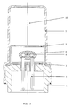
- An LF5 pyrotechnic ignition pill based on a mixture of fuels of aluminium + zirconium and potassium perchlorate and of alkaline cupric nitrate oxidizers forming the electric initiator 4 provided with ethyl cellulose and silicone lacquer was joined conductively by welding with the contacts 2, which were insulated in advance in the insulation and sealing mass 3 based on polyphenylene sulphide (PPS) and also in the sealing sleeve 9 based on epoxy resin. 100 mg of 75/25 potassium nitrate/boron mixture was used as an enhancing flash composition 8.
- This mixture was placed in the inner cover 5 comprising an aluminium cup having a wall thickness of 0.4 mm and depth of the pre-shaped bottom of 0,25 mm, the pre-shaping of the bottom being achieved by reducing its thickness.
- the whole created in this manner formed the assembled carrier 6 , which in the place of the carrying sleeve 1 was laser welded with the outer cover 7 comprising the aluminium cup with the wall thickness of 0.4 mm containing the propellant 10 - in this case 1200 mg of one-component nitrocellulose smokeless gun powder.
- This gas generator is illustrated in Figure 1.
- An LF5 pyrotechnic pill based on a mixture of fuels of aluminium + zirconium and potassium perchlorate and of alkaline cupric nitrate oxidizers forming the electric initiator 4 coated with ethyl cellulose and silicone lacquer was formed on the contacts 2 , which were insulated in advance in the insulation and sealing mass 3 based on epoxy resin.
- As an enhancing flash composition 8 120 mg of 75/25 potassium nitrate/boron mixture was used. This mixture was placed in the inner cover 5 comprising an aluminium cup having a wall thickness of 0.4 mm and depth of the pre-shaped bottom of 0,25 mm.
- An LF5 pyrotechnic pill based on a mixture of fuels of aluminium + zirconium and potassium perchlorate and of alkaline cupric nitrate oxidizers forming the electric initiator 4 provided with ethyl cellulose and silicone lacquer was joined conductively by welding with the contacts 2 , which were insulated in advance in the insulation and sealing mass 3 based on polyphenylene sulphide (PPS) and also in the sealing sleeve 9 based on epoxy resin.
- PPS polyphenylene sulphide
- 85 mg of 75/25 potassium nitrate/boron mixture was used as an enhancing flash composition 8 .
- This mixture was placed in the inner cover 5 comprising a plastic cup having a wall thickness of 0.4 mm.
- the assembled carrier 6 was laser welded with the outer cover 7 comprising the aluminium cup with the wall thickness of 0.5 mm containing the propellant 10 - in this case 1200 mg of one-component nitrocellulose smokeless gun powder.
- the gas generator is depicted in Figure 3.
- the compact gas generators according to the present invention including the method of producing them can be used extensively primarily in the automotive industry.
Landscapes
- Physics & Mathematics (AREA)
- Fluid Mechanics (AREA)
- Engineering & Computer Science (AREA)
- Mechanical Engineering (AREA)
- Feeding, Discharge, Calcimining, Fusing, And Gas-Generation Devices (AREA)
- Air Bags (AREA)
Abstract
Description
- This invention relates to a compact type of an electrically initiated gas generator intended for electric pyrotechnic systems. The gas generator is particularly suitable as an element of safety systems for pre-tensioners of safety seat belts in automobiles but also for other related applications. Further, the invention concerns also a method of manufacturing the compact gas generator.
- As it is known in the given field, pyrotechnic components for electrically initiated pyrotechnic systems intended for the automotive industry are generally based on the known design of what is known as a GTMS (glass to metal sealed) squib, in which a high degree of protection against humidity is achieved by combining a laser weld of metals (metal carrier with a metal cup) and sealing the metals with a glass seal (placing contacts into the metal carrier). These initiators are used extensively mainly thanks to their high resistance to humidity and also for their high level of safe current (0.4 A/10 s). Their disadvantage is, on the other hand, high price.
- Besides these resistant and very costly pyrotechnic components also cheaper solutions, known as, for instance, plastics squibs, are employed for electric initiators in automobiles. However, the plastic squibs provide a lower level of air-tightness and also less body resistance to back pressure. Also, the level of the safe current is usually lower than that of the GTMS squibs (typically 0.2 A to 0.25 A for a period of 10 s.).
- The gas generators used in electric pyrotechnic systems till now exhibit - in comparison with the present requirements - a lower environmental resistance (high humidity, etc.) and also a relatively complicated structure and require use of expensive initiators (GTMS squib, plastics squib, etc.). In contrast to the solutions used up to now, the present invention featuring a compact design aims at achieving a markedly higher air-tightness and humidity resistance while reducing simultaneously the product price.
- The above disadvantages and shortcomings of the pyrotechnic systems known till now are to a great extent eliminated by the compact gas generators for electric pyrotechnic systems according to this invention and by the method of producing it. The nature of the invention can be described as follows: the compact gas generator comprises a carrying sleeve, in which contacts pass through an insulation and a sealing mass and enter the electric initiator enclosed in an inner cover, with all the parts described up to now forming together an assembled carrier on which an outer cover is placed from above. The joint of the assembled carrier with the outer cover is formed with advantage with a laser weld. The inner cover may contain an enhancing flash composition. In the preferred embodiment, a sealing sleeve is inserted between the carrying sleeve and the contact. The outer cover may contain a propellant and the material of both the outer and inner covers is most frequently a metal or a plastic.
- Further, the nature of the invention is a method of manufacturing the compact gas generator for electric pyrotechnic systems consisting in fixing the contacts in the insulation and sealing material, subsequently creating an electric initiator on the contacts, encasing the said initiator in the inner cover and covering the assembled carrier from above with the outer cover, with which it is connected hermetically in the place of the carrying sleeve. The connection with the carrying sleeve is obtained with advantage by laser welding.
- An advantage of the compact gas generator according to the invention, contrary to the comparable solutions employed till now, is the use of a compact design resulting in a markedly higher air-tightness and humidity resistance while reducing the price of the gas generator.
- The compact design of the gas generator according to this invention is achieved with advantage by sealing hermetically through a laser weld the outer cover with the carrying sleeve and also by using an insulation and sealing mass between contacts and the carrying sleeve, the effect of the insulation and sealing mass being increased with advantage by utilizing a sealing sleeve. A cheap and hermetically untight type of an electric initiator (an electric pill or a detonator /a fuse/) is fixed onto the contacts using a conducting connection. The insulation and sealing mass forms a support bed for this electric initiator and also for the enhancing flash composition, which is placed with advantage in the inner cover.
- An alternative method of producing the compact gas generator according to the present invention consists in welding the electric initiator with the contacts located in a preformed bed made from the sealing and insulation mass, assembling it with the inner cover and the enhancing flash composition and finally providing the assembled carrier with the outer cover filled with the propellant and welding the carrier and the outer cover together with laser.
- The enhancing flash composition is dosed using methods well known in the given field (in bulk, pressed, dropped on, rubbed into and other forms) and covered with, for instance, an aluminium fringed inner cover with a pre-shaped bottom for an easier opening during the product operation. The unit described above is called, as already mentioned, the assembled carrier. The compact gas generator is then produced by joining the assembled carrier, for instance by laser welding, with the aluminium outer cover containing with advantage a propellant. By the propellant a pyrotechnic gas releasing composition, green propellant or nitrocellulose and other smokeless powders are understood.
- Specific embodiments of the compact gas generators according to the present invention are shown in the attached drawings, of which:
- Figure 1 shows a compact gas generators according to example 1 - axial sectional view,
- Figure 2 shows a compact gas generators according to example 2 - axial sectional view,
- Figure 3 shows a compact gas generators according to example 3 - axial sectional view.
- To describe the nature of the invention in a greater detail the following examples of a specific embodiment of the compact pyrotechnic gas generator with an increased resistance and the method of producing it are provided.
- An LF5 pyrotechnic ignition pill based on a mixture of fuels of aluminium + zirconium and potassium perchlorate and of alkaline cupric nitrate oxidizers forming the
electric initiator 4 provided with ethyl cellulose and silicone lacquer was joined conductively by welding with thecontacts 2, which were insulated in advance in the insulation and sealingmass 3 based on polyphenylene sulphide (PPS) and also in the sealingsleeve 9 based on epoxy resin. 100 mg of 75/25 potassium nitrate/boron mixture was used as an enhancingflash composition 8. This mixture was placed in theinner cover 5 comprising an aluminium cup having a wall thickness of 0.4 mm and depth of the pre-shaped bottom of 0,25 mm, the pre-shaping of the bottom being achieved by reducing its thickness. The whole created in this manner formed the assembledcarrier 6, which in the place of the carryingsleeve 1 was laser welded with theouter cover 7 comprising the aluminium cup with the wall thickness of 0.4 mm containing the propellant 10 - in this case 1200 mg of one-component nitrocellulose smokeless gun powder. This gas generator is illustrated in Figure 1. - An LF5 pyrotechnic pill based on a mixture of fuels of aluminium + zirconium and potassium perchlorate and of alkaline cupric nitrate oxidizers forming the
electric initiator 4 coated with ethyl cellulose and silicone lacquer was formed on thecontacts 2, which were insulated in advance in the insulation and sealingmass 3 based on epoxy resin. As an enhancingflash composition 8, 120 mg of 75/25 potassium nitrate/boron mixture was used. This mixture was placed in theinner cover 5 comprising an aluminium cup having a wall thickness of 0.4 mm and depth of the pre-shaped bottom of 0,25 mm. The whole created in this manner formed the assembledcarrier 6, which in the place of the carryingsleeve 1 was laser welded with theouter cover 7 comprising the aluminium cup with the wall thickness of 0.4 mm containing the propellant 10 - in this case 1400 mg of the "green propellant". The gas generator described above is shown in Figure 2. - An LF5 pyrotechnic pill based on a mixture of fuels of aluminium + zirconium and potassium perchlorate and of alkaline cupric nitrate oxidizers forming the
electric initiator 4 provided with ethyl cellulose and silicone lacquer was joined conductively by welding with thecontacts 2, which were insulated in advance in the insulation and sealingmass 3 based on polyphenylene sulphide (PPS) and also in the sealingsleeve 9 based on epoxy resin. 85 mg of 75/25 potassium nitrate/boron mixture was used as an enhancingflash composition 8. This mixture was placed in theinner cover 5 comprising a plastic cup having a wall thickness of 0.4 mm. In the place of the carryingsleeve 1 the assembledcarrier 6 was laser welded with theouter cover 7 comprising the aluminium cup with the wall thickness of 0.5 mm containing the propellant 10 - in this case 1200 mg of one-component nitrocellulose smokeless gun powder. Such a gas generator is depicted in Figure 3. - The compact gas generators according to the present invention including the method of producing them can be used extensively primarily in the automotive industry.
Claims (10)
- A compact gas generator for electrically initiated pyrotechnic systems, wherein the said compact gas generator comprises a carrying sleeve (1), in which contacts (2) pass through an insulation and sealing mass (3) and enter an electric initiator (4) encased with an inner cover (5), with all the parts mentioned till now forming together the assembled carrier (6), on which an outer cover (7) is placed from above.
- A compact gas generator for electrically initiated pyrotechnic systems according to Claim 1, wherein the assembled carrier (6) is joined with the outer cover (7) with a laser weld.
- A compact gas generator for electrically initiated pyrotechnic systems according to Claim 1, wherein the inner cover (5) contains an enhancing flash composition (8).
- A compact gas generator for electrically initiated pyrotechnic systems according to Claim 1, wherein a sealing sleeve (9) is inserted between the carrying sleeve (1) and contacts (2).
- A compact gas generator for electrically initiated pyrotechnic systems according to Claim 1, wherein the outer cover (7) contains a propellant (10).
- A compact gas generator for electrically initiated pyrotechnic systems according to Claim 1, wherein the material from which the inner cover (5) and outer cover (7) are made is a metal or a plastic.
- A method of producing a compact gas generator for electrically initiated pyrotechnic systems according to Claim 1, wherein the contacts (2) are fixed in the insulation and sealing mass (3), subsequently an electric initiator (4) is created on or connected with the contacts (2) and covered with the inner cover (5) and the carrier (6) thus assembled is covered from above with the outer cover (7), with which it is hermetically connected in the place of the carrying sleeve (1).
- A method of producing a compact gas generator for electrically initiated pyrotechnic systems according to Claim 7, wherein the connection of the outer cover (7) with the carrying sleeve (1) is achieved by laser welding.
- A method of producing a compact gas generator for electrically initiated pyrotechnic systems according to Claim 7, wherein the enhancing flash composition (8) is placed into the space of the inner cover (5).
- A method of producing a compact gas generator for electrically initiated pyrotechnic systems according to Claim 7, wherein the propellant (10) is placed into the space of the outer cover (7).
Applications Claiming Priority (1)
| Application Number | Priority Date | Filing Date | Title |
|---|---|---|---|
| CZ20060295A CZ2006295A3 (en) | 2006-05-09 | 2006-05-09 | Compact gas generator for electrical pyrotechnic systems and process for producing thereof |
Publications (2)
| Publication Number | Publication Date |
|---|---|
| EP1854680A2 true EP1854680A2 (en) | 2007-11-14 |
| EP1854680A3 EP1854680A3 (en) | 2008-07-16 |
Family
ID=38335656
Family Applications (1)
| Application Number | Title | Priority Date | Filing Date |
|---|---|---|---|
| EP07466010A Withdrawn EP1854680A3 (en) | 2006-05-09 | 2007-05-04 | Compact gas generator for electric pyrotechnic systems and a method of producing it |
Country Status (2)
| Country | Link |
|---|---|
| EP (1) | EP1854680A3 (en) |
| CZ (1) | CZ2006295A3 (en) |
Cited By (2)
| Publication number | Priority date | Publication date | Assignee | Title |
|---|---|---|---|---|
| WO2020149399A1 (en) * | 2019-01-18 | 2020-07-23 | 日本化薬株式会社 | Gas generator |
| DE102022131843A1 (en) | 2022-12-01 | 2024-06-06 | Zf Airbag Germany Gmbh | IGNITION UNIT OF A GAS GENERATOR AND METHOD FOR PRODUCING AN IGNITION UNIT |
Families Citing this family (2)
| Publication number | Priority date | Publication date | Assignee | Title |
|---|---|---|---|---|
| CZ305258B6 (en) * | 2007-11-28 | 2015-07-08 | Indet Safety Systems A. S. | Electro-pyrotechnic cable gas generator based on electric primer and method for producing thereof |
| CZ305260B6 (en) * | 2009-06-29 | 2015-07-08 | Indet Safety Systems A.S. | Plastic gas generator and process for producing thereof |
Citations (1)
| Publication number | Priority date | Publication date | Assignee | Title |
|---|---|---|---|---|
| JP2005280585A (en) | 2004-03-30 | 2005-10-13 | Nippon Kayaku Co Ltd | Metallic holder with electrode pin, its method of manufacture, and gas producer |
Family Cites Families (6)
| Publication number | Priority date | Publication date | Assignee | Title |
|---|---|---|---|---|
| CA2396863A1 (en) * | 2000-01-12 | 2001-07-19 | Nippon Kayaku Kabushiki Kaisha | Gas generator |
| DE60236876D1 (en) * | 2001-08-09 | 2010-08-12 | Nippon Kayaku Kk | GAS GENERATOR |
| US7284488B2 (en) * | 2002-07-19 | 2007-10-23 | Nippon Kayaku Kabushiki Kaisha | Gas generator |
| JP2004271030A (en) * | 2003-03-07 | 2004-09-30 | Indet Safety Systems As | Header device, and sparker and gas generator having the same |
| US7316187B2 (en) * | 2004-09-17 | 2008-01-08 | Autoliv Asp, Inc. | Radial discharge actuator device |
| US7210703B2 (en) * | 2004-10-26 | 2007-05-01 | Autoliv Asp, Inc. | One-piece initiator device for inflators |
-
2006
- 2006-05-09 CZ CZ20060295A patent/CZ2006295A3/en unknown
-
2007
- 2007-05-04 EP EP07466010A patent/EP1854680A3/en not_active Withdrawn
Patent Citations (1)
| Publication number | Priority date | Publication date | Assignee | Title |
|---|---|---|---|---|
| JP2005280585A (en) | 2004-03-30 | 2005-10-13 | Nippon Kayaku Co Ltd | Metallic holder with electrode pin, its method of manufacture, and gas producer |
Cited By (4)
| Publication number | Priority date | Publication date | Assignee | Title |
|---|---|---|---|---|
| WO2020149399A1 (en) * | 2019-01-18 | 2020-07-23 | 日本化薬株式会社 | Gas generator |
| JP2020116968A (en) * | 2019-01-18 | 2020-08-06 | 日本化薬株式会社 | Gas generator |
| US12134365B2 (en) | 2019-01-18 | 2024-11-05 | Nippon Kayaku Kabushiki Kaisha | Gas generator |
| DE102022131843A1 (en) | 2022-12-01 | 2024-06-06 | Zf Airbag Germany Gmbh | IGNITION UNIT OF A GAS GENERATOR AND METHOD FOR PRODUCING AN IGNITION UNIT |
Also Published As
| Publication number | Publication date |
|---|---|
| EP1854680A3 (en) | 2008-07-16 |
| CZ2006295A3 (en) | 2007-11-21 |
Similar Documents
| Publication | Publication Date | Title |
|---|---|---|
| EP1731383B1 (en) | Metal holder with electrode pin, method of manufacturing the metal holder, and gas generator | |
| US5454320A (en) | Air bag initiator | |
| US6009809A (en) | Bridgewire initiator | |
| AU727918B2 (en) | Initiator with loosely packed ignition charge and method of assembly | |
| US20050235858A1 (en) | Plastic encapsulated energetic material initiation device | |
| JPH07286800A (en) | Igniter for air bag and its preparation | |
| CN109017667A (en) | The method of igniting unit of inflator, inflator, air bag module, Vehicle security system and manufacture igniting unit for inflator | |
| EP1854680A2 (en) | Compact gas generator for electric pyrotechnic systems and a method of producing it | |
| WO2002092539A1 (en) | Igniting agent composition, and igniter using the igniting agent composition | |
| TW482889B (en) | Squib and method of manufacture thereof | |
| CN109813188A (en) | A kind of safe electronic ignition and detonation part and safe electronic ignition and detonation detonator | |
| JPH11240412A (en) | Gas generator for activation of passenger restraint system | |
| WO2021054117A1 (en) | Igniter assembly and method for assembling igniter assembly | |
| CN113661097A (en) | The gas generator | |
| EP2589920A2 (en) | High performance initiator | |
| US20030221577A1 (en) | Standalone ignition subassembly for detonators | |
| CZ2009415A3 (en) | Plastic gas generator | |
| WO2021245967A1 (en) | Gas generator and method for producing same | |
| CZ16673U1 (en) | Compact gas producer for electrical pyrotechnic systems | |
| US20080282927A1 (en) | Gas generator | |
| JP3329204B2 (en) | Non-explosive composition for igniter and flash igniter using the same | |
| WO2003100346A1 (en) | Detonator with an ignition element having a transistor-type sealed feedthrough | |
| TW469340B (en) | Squib | |
| CZ24226U1 (en) | High pressure-resistant gas generator | |
| CN201046945Y (en) | Modified carbohydrazide and perchlorate complex initiating explosive commercial detonator |
Legal Events
| Date | Code | Title | Description |
|---|---|---|---|
| PUAI | Public reference made under article 153(3) epc to a published international application that has entered the european phase |
Free format text: ORIGINAL CODE: 0009012 |
|
| AK | Designated contracting states |
Kind code of ref document: A2 Designated state(s): AT BE BG CH CY CZ DE DK EE ES FI FR GB GR HU IE IS IT LI LT LU LV MC MT NL PL PT RO SE SI SK TR |
|
| AX | Request for extension of the european patent |
Extension state: AL BA HR MK YU |
|
| PUAL | Search report despatched |
Free format text: ORIGINAL CODE: 0009013 |
|
| 17P | Request for examination filed |
Effective date: 20080512 |
|
| AK | Designated contracting states |
Kind code of ref document: A3 Designated state(s): AT BE BG CH CY CZ DE DK EE ES FI FR GB GR HU IE IS IT LI LT LU LV MC MT NL PL PT RO SE SI SK TR |
|
| AX | Request for extension of the european patent |
Extension state: AL BA HR MK RS |
|
| AKX | Designation fees paid |
Designated state(s): AT BE BG CH CY CZ DE DK EE ES FI FR GB GR HU IE IS IT LI LT LU LV MC MT NL PL PT RO SE SI SK TR |
|
| 17Q | First examination report despatched |
Effective date: 20100413 |
|
| STAA | Information on the status of an ep patent application or granted ep patent |
Free format text: STATUS: THE APPLICATION IS DEEMED TO BE WITHDRAWN |
|
| 18D | Application deemed to be withdrawn |
Effective date: 20100824 |