EP1854631B1 - Electrostatic printing apparatus using electric charge concentration at the ejection nozzle opening of a capillary - Google Patents
Electrostatic printing apparatus using electric charge concentration at the ejection nozzle opening of a capillary Download PDFInfo
- Publication number
- EP1854631B1 EP1854631B1 EP06123329A EP06123329A EP1854631B1 EP 1854631 B1 EP1854631 B1 EP 1854631B1 EP 06123329 A EP06123329 A EP 06123329A EP 06123329 A EP06123329 A EP 06123329A EP 1854631 B1 EP1854631 B1 EP 1854631B1
- Authority
- EP
- European Patent Office
- Prior art keywords
- capillary
- solution
- printing apparatus
- capillary nozzle
- droplet printing
- Prior art date
- Legal status (The legal status is an assumption and is not a legal conclusion. Google has not performed a legal analysis and makes no representation as to the accuracy of the status listed.)
- Ceased
Links
Images





Classifications
-
- B—PERFORMING OPERATIONS; TRANSPORTING
- B41—PRINTING; LINING MACHINES; TYPEWRITERS; STAMPS
- B41J—TYPEWRITERS; SELECTIVE PRINTING MECHANISMS, i.e. MECHANISMS PRINTING OTHERWISE THAN FROM A FORME; CORRECTION OF TYPOGRAPHICAL ERRORS
- B41J2/00—Typewriters or selective printing mechanisms characterised by the printing or marking process for which they are designed
- B41J2/005—Typewriters or selective printing mechanisms characterised by the printing or marking process for which they are designed characterised by bringing liquid or particles selectively into contact with a printing material
- B41J2/01—Ink jet
- B41J2/015—Ink jet characterised by the jet generation process
- B41J2/04—Ink jet characterised by the jet generation process generating single droplets or particles on demand
- B41J2/06—Ink jet characterised by the jet generation process generating single droplets or particles on demand by electric or magnetic field
Definitions
- the present invention relates to a droplet printing apparatus using capillary electric charge concentration, and more particularly, to a droplet printing apparatus using capillary electric charge concentration to stably supply using a capillary force a solution to be ejected to a nozzle.
- a droplet printing apparatus is used to eject very small droplet units of a solution on a substrate or paper.
- droplet ejection methods In an ink jet method, heat is supplied to a solution (ink) that is then ejected on a piece of paper or other material.
- this method is not appropriate when the characteristic of a solution to be ejected changes with heat.
- a solution droplet including a biomolecule such as a nucleic acid, a protein, a living cell, a virus, or bacteria has to be ejected to manufacture a biochip
- a droplet printing apparatus by which a solution can be ejected without heating is required.
- An example of such apparatus is an apparatus ejecting picoliter-sized droplets using ultrasonic energy.
- EP 0780229 A1 and EP 1623832 A2 disclose electrostatic inkjet printheads in which ink ejection openings are provided with ejection electrodes and ink guides, respectively, which have a conical tip and protrude through the openings.
- GB 729,842 discloses a device for electrostatic application of liquid coatings materials such as lacquer.
- a droplet printing apparatus which uses capillary electric charge concentration for manufacturing a biochip
- the apparatus comprising: a reservoir which contains a solution comprising a biomolecule; a capillary nozzle in fluid communication with the solution contained in the reservoir; and an open circuit type voltage supplier arranged to supply a voltage to the solution
- the apparatus is characterized in that a the capillary nozzle is a capillary tube, a back-end part of which is immersed in the solution contained in the reservoir and a front-end part of which is exposed outside of the solution contained in the reservoir, the capillary nozzle being arranged to transmit the solution to the front-end part by a capillary force.
- the capillary nozzle may be disposed in a vertical upward direction in the reservoir. Also, the capillary nozzle may be formed of a conductive material or a non-conductive material. When the capillary nozzle is formed of a non-conductive material, a conductive material layer may be further included in an inner wall of the capillary nozzle.
- the open circuit type voltage supplier may supply a voltage to the solution through an electrode immersed in the solution contained in the reservoir.
- an inner wall of the capillary nozzle may be hydrophilic and a hydrophobic coating layer may be further included in the front-end part of the capillary nozzle.
- the inner wall of the capillary nozzle may be also hydrophobic and a hydrophilic coating layer may be further included in the front-end part of the capillary nozzle.
- the former case is suitable when a solvent of the solution to be ejected is a polar solvent and the latter case is suitable when a solvent of the solution to be ejected is a non-polar solvent.
- a plurality of capillary nozzles may be disposed in the reservoir.
- a droplet printing apparatus using capillary electric charge concentration for manufacturing a biochip comprising: a plurality of droplet printing modules arranged two-dimensionally; and a target member on which droplets ejected from each of the droplet printing modules are placed in a predetermined pattern, wherein each of the droplet printing modules comprises the droplet printing apparatus described above.
- the solutions in the reservoirs of the droplet printing modules may have different concentrations.
- Various patterns of droplets can be formed according to an arrangement pattern of the droplet printing modules.
- the capillary nozzle may be disposed in a vertical upward direction in the reservoir. Also, the capillary nozzle may be formed of a conductive material or a non-conductive material. When the capillary nozzle is formed of a non-conductive material, a conductive material layer may be further included in an inner wall of the capillary nozzle.
- the open circuit type voltage supplier may supply a voltage to the solution through an electrode immersed in the solution contained in the reservoir.
- the inner wall of the capillary nozzle may be hydrophilic and a hydrophobic coating layer may be further included in the front-end part of the capillary nozzle.
- the inner wall of the capillary nozzle may be also hydrophobic and a hydrophilic coating layer may be further included in the front-end part of the capillary nozzle.
- the former case is suitable when a solvent of the solution to be ejected is a polar solvent and the latter case is suitable when a solvent of the solution to be ejected is a non-polar solvent.
- a plurality of capillary nozzles may be disposed in one reservoir and the open circuit type voltage supplier may supply a voltage to the solution through an electrode immersed in the solution contained in the reservoir.
- the present invention provides a droplet printing apparatus that can eject significantly small-sized droplets through a nozzle at short intervals while maintaining constant the size of droplets and can be miniaturized.
- the present invention also provides a droplet printing apparatus which improves a degree of integration of biochips and manufacture effectiveness thereof when the apparatus is used to manufacture biochips.
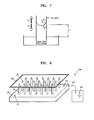
- FIG. 1 is a view schematically illustrating a droplet printing apparatus 101 according to an embodiment of the present invention.
- the droplet printing apparatus 101 includes a reservoir 20 containing a solution 25, a capillary nozzle 10, a back-end part of which is immersed in the solution 25 to transmit the solution 25 to a front-end part of the capillary nozzle 10 by a capillary force, a target member 30 spaced apart from the front-end part of the capillary nozzle 10 at a predetermined distance, and an open circuit type voltage supplier 40 which supplies a voltage to the solution 25.
- the predetermined distance refers to a distance from which a droplet can be ejected to the target member 30. Therefore, the predetermined distance varies according to the amplitude of a supplied voltage, an electrolyte concentration of the solution 25, the surface tension at the surface of the solution 25, and the like.
- the capillary nozzle 10 can be disposed in a vertical upward direction in the reservoir 20 such that the front-end part of the capillary nozzle 10 is not immersed in the solution 25.
- the target member 30 is disposed above the front-end part of the capillary nozzle 10.
- the capillary nozzle 10 can be also disposed slightly inclined or in a horizontal or vertical downward direction. When the capillary nozzle 10 is disposed in a vertical upward direction, the height of the capillary nozzle 10 exposed above the surface of the solution 25 can be determined to be in a range corresponding to a capillary force strong enough to lift the solution 25 in the capillary nozzle 10.
- the capillary nozzle 10 can be formed of a conductive material such as a metal, for example, gold, platinum, copper, or aluminum, or a conductive polymer.
- a voltage can be supplied to the solution 25 from the open circuit type voltage supplier 40 via a lead line 41 directly connected to the capillary nozzle 10.
- the capillary nozzle 10 can be formed of a non-conductive material, in which case the capillary nozzle 10 comprises a conductive material layer in an inner wall (refer to FIG. 5 ). In this case, a voltage can also be supplied to the solution 25 from the open circuit type voltage supplier 40 via the lead line 41 directly connected to the conductive material layer in the inner wall of the capillary nozzle 10.
- the target member 30 may be a composite substrate formed of at least one material or two materials selected from the group consisting of silicon, glass, and polymer, but not limited thereto. Other materials can be used to form the target member 30 according to the use of the droplet printing apparatus 101. Droplets of the solution 25 ejected from the front-end part of the capillary nozzle 10 are attached to the surface of the target member 30.
- the surface of the target member 30 is coated with at least one material or two materials selected from the group consisting of an amine group, a carboxyl group, streptavidine, biotin, thiol, and Poly-L-Lysine, and thus, the adhesion of biomolecules included in the droplets to the target member 30 can be improved.
- the target member 30 may be a transparent substrate. If the target member 30 is transparent, droplets printed on the opposite side of the capillary nozzle 10 can be optically detected.
- the target member 30 can be also connected to ground.
- the open circuit type voltage supplier 40 is electrically connected to the inner wall of the capillary nozzle 10.
- a voltage having a predetermined waveform can be supplied to the capillary nozzle 10 from the open circuit type voltage supplier 40 via the lead line 41.
- the voltage can be an AC voltage or a DC voltage and the predetermined waveform can be a sine wave, a triangular wave, or a waveform obtained by overlapping at least two waveforms.
- the waveform and strength of the supplied voltage may vary according to the size of droplets and a property of the solution 25.
- the solution 25 contained in the capillary nozzle 10 is electrically charged by the voltage supplied from the open circuit type voltage supplier 40.
- the solution 25 contained in the reservoir 20 is transmitted by a capillary force from the back-end part of the capillary nozzle 10 immersed in the solution 25 to the front-end part of the capillary nozzle 10 exposed outside of the solution 25.
- the solution 25 which reaches the front-end part of the capillary nozzle 10 and gathers thereon instead of overflowing due to a surface tension.
- the shape of the solution 25 gathered on the capillary nozzle 10 has various forms according to a contact angle of the capillary nozzle 10 with the solution 25.
- FIG. 2 is a view schematically illustrating a droplet printing apparatus 102 according to another embodiment of the present invention, in a state where a voltage is supplied to a solution through an electrode (not shown) immersed in the solution.
- the droplet printing apparatus 102 is almost the same with the droplet printing apparatus 101 described above. The only difference is that the open circuit type voltage supplier 40 supplies a voltage via a lead line 43 to the electrode immersed in a solution 25 contained in a reservoir 20.
- the electrode can be formed of various materials, and may also be an end part of the lead line 43 from which coating is removed.
- a capillary nozzle 10 may be formed of a conductive material or a non-conductive material.
- FIG. 3 is a view schematically illustrating a droplet printing apparatus 103 including two capillary nozzles 10 placed in a reservoir according to another embodiment of the present invention. Although only two capillary nozzles 10 are shown in FIG. 3 , more than two capillary nozzles 10 may be used.
- the droplet printing apparatus 103 is almost the same with the droplet printing apparatus 102 described above. The only difference is that two capillary nozzles 10 are disposed in the reservoir 20. Since, the open circuit type voltage supplier 40 supplies a voltage to a solution 25 contained in the reservoir 20 through soaked electrode instead of the capillary nozzles 10, droplets can be ejected from a number of capillary nozzles 10 without wiring each of the capillary nozzles 10.
- FIG. 4 shows a cross-sectional view and a plane view of the capillary nozzle 10 according to an embodiment of the present invention.
- the capillary nozzle 10 is in the form of a capillary tube.
- a wall 15 of the capillary nozzle 10 may be formed of a conductive material or a non-conductive material.
- the conductive material may be a metal that has an anti-corrosive property against the solution 25 to be ejected.
- the non-conductive material may be glass or a plastic material.
- Fig. 5 shows a cross-sectional view and a plane view of a capillary nozzle 11 having a conductive material layer 16 included in an inner wall thereof, according to an embodiment of the present invention.
- a wall 15 of the capillary nozzle 11 is formed of glass and the conductive material layer 16 may be an ITO (Indium Tin Oxide) layer.
- the conductive material layer 16 can be connected to the open circuit type voltage supplier 40 via the lead line.
- FIG. 6 shows a cross-sectional view and a plane view of a capillary nozzle 12 having a coating layer 17 included in a front-end part thereof.
- the coating layer 17 may be further included in the inner surface of the front-end part of a wall 15 of the capillary nozzle 12.
- the coating layer 17 may be a hydrophobic coating layer if the solution 25 is an aqueous solution.
- the coating layer 17 may be formed, for example, of a material having low hydrophilicity with respect to the inner surface of the wall 15 of the front-end part of the capillary nozzle 12.
- the coating layer 17 increases or reduces a contact angle at the front-end part of the capillary nozzle 12 according to the material property thereof and thus droplets can form in the front-end part of the capillary nozzle 12 with an appropriate size to be ejected.
- FIG. 7 is a conceptual view of a transportation principle due to a capillary force in a capillary nozzle.
- Gravity (Fg) and a capillary force (Fc) act in the capillary nozzle.
- the capillary nozzle is disposed in a vertical upward direction, the gravity (Fg) and capillary force (Fc) occur at a predetermined height (H) in opposite directions.
- the height (H) is the maximum height at which the solution can be transmitted using the capillary force (Fc).
- the height of the capillary nozzle of the droplet printing apparatus according to the present invention is lower than the maximum height so that when droplets are ejected from the front-end part of the capillary nozzle the amount of solution corresponding to the volume of the droplets ejected can be immediately and stably supplemented. Since the solution is supplied to the front-end part of the capillary nozzle via the capillary force (Fc), the surface of the solution, immediately after the droplets are ejected, can be stabilized promptly and thus, the repeatability of the droplet printing apparatus can be greatly improved.
- FIG. 8 is a perspective view schematically illustrating a droplet printing apparatus 104 having a plurality of capillary nozzles 10 disposed in one reservoir 20 according to an embodiment of the present invention.
- the capillary nozzles 10 can be disposed in any desired pattern in the reservoir 20. According to the arrangement of the capillary nozzles 10, droplets 27 ejected from the capillary nozzles 10 and seated on the target member 30 form a regular pattern.
- the reservoir 20 includes an inlet hole 21 and an outlet hole 22, for respectively receiving and discharging a solution, and a lead line 43 connected to an open circuit type voltage supplier 40 can be electrically connected to the solution contained in the reservoir 20, for example, through the outlet hole 22.
- the lead line 43 can be connected to an electrode (not illustrated) immersed in the solution contained in the reservoir 20.
- the electrode can be formed of any materials having an anti-corrosive property against the solution.
- distances between the electrode and the front-end part of each of the capillary nozzles 10 should be equal to one another.
- the capillary nozzles 10 can be also formed of insulating materials. In this case, an electrical interaction between the capillary nozzles 10 is decreased and thus, integration of the capillary nozzles is possible.
- FIG. 9 is a perspective view schematically illustrating a droplet printing apparatus 105 including a plurality of printing modules according to an embodiment of the present invention.
- the droplet printing modules are arranged two-dimensionally.
- Droplets 27 or 27' are ejected from each of the droplet printing modules on a target member 30 in a predetermined pattern.
- Each of the droplet printing modules includes a reservoir 20 or 20', containing a solution to be ejected, and a capillary nozzle 10, a back-end part of which is immersed in the solution contained in the reservoir 20 or 20', a front-end part of which is spaced apart from the target member 30 at a predetermined distance, wherein he back-end part transmits the solution to the front-end part of the capillary nozzle 10 by a capillary force, and an open circuit type voltage supplier (not illustrated) which supplies a voltage to the solution.
- the reservoirs 20 and 20' may contain different kinds of solutions or solutions of different concentrations, if necessary. In this case, the droplet 27' is different from the droplet 27.
- Each of the reservoirs 20 and 20' have an inlet hole 21 and an outlet hole 22.
- the open circuit type voltage supplier (not illustrated) may supply a voltage through an inner wall of the capillary nozzle 10 as in the droplet printing apparatus 101 of FIG. 1 or through an electrode (not illustrated) immersed in the solution contained in the reservoir 20 as in the droplet printing apparatus 102 of FIG. 2 .
- FIG. 10A is a graph showing a volume of droplet ejected repeatedly using the apparatus of FIG. 1 having a SUS capillary nozzle.
- the droplet printing apparatus used in the experiment includes capillary nozzles formed of SUS and a target member formed of a glass.
- the distance between the front-end part of the capillary nozzles 10 and the target member 30 is 200 ⁇ m and a voltage is supplied at an interval of 3.5 seconds and droplet ejection is repeatedly performed 80 times.
- the average volume is 33 pL.
- FIG. 10B is a graph showing a frequency distribution chart of the droplet volumes of FIG. 10A . As shown in FIG. 10B , when droplet ejection is performed repeatedly 80 times, the average volume of the droplet is 33 pl. and the standard deviation is 5.3, which mean an ejection reliability of 95 %.
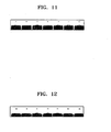
- FIG. 11 shows photographs of droplets ejected repeatedly using the apparatus of FIG. 1 .
- a droplet is ejected 7 times at a 3 second interval using the apparatus used in the experiment described with respect to FIG. 10A .
- the open circuit type voltage supplier is directly connected to the capillary nozzle 10 to supply the voltage.
- the lower parts of the photographs show the front-end part of the capillary nozzle 10 and a convex surface at the front-end part of the capillary nozzle 10 is the surface of the solution.
- the upper part of the photographs show the target member formed of a glass and each droplet is attached to the bottom surface of the target member. As shown in the photographs, the droplets have regular sizes.
- FIG. 12 shows photographs of droplets ejected repeatedly using the apparatus of FIG. 2
- the open circuit type voltage supplier supplies the voltage through the electrode immersed in the solution contained in the reservoir 20.
- the volume of the droplet is bigger than in FIG. 11 .
- the volumes of the droplets become regular.
- FIG. 13 shows photographs of a process of droplet ejection using the apparatus of FIG. 3 .
- the lower parts of the photograph show the capillary nozzle 10 and the upper parts of the photograph show a reflection of the capillary nozzle from the glass substrate.
- Two capillary nozzles are disposed at an interval of 3 mm.
- the voltage is supplied to the electrode immersed in the solution 25
- picoliter sized droplets are ejected at the same time.
- the capillary nozzles 10 are formed of a conductive material and the voltage is directly supplied thereto, noise appears between adjacent capillary nozzles and thus, there is a limitation of integrating the capillary nozzles 10.
- a plurality of capillary nozzles 10 can be disposed at short intervals of 3 mm.
- FIGS. 14 through 17 refer to experiments performed using a droplet printing apparatus having the structure according to the embodiment of FIG. 2 and the capillary nozzles 10 formed of glass.
- FIG. 14 is a photograph showing a front-end part of the glass capillary nozzle 10.
- the external diameter and the inside diameter of the glass capillary nozzle are 1.5 mm and 0.84 mm, respectively.
- the height from the surface of the solution to the front-end part of the capillary nozzle is 2.57 mm.
- the distance between the front-end part of the capillary nozzle 10 and the target member is 500 ⁇ m.
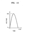
- FIG. 15 is a graph showing a waveform of a voltage supplied by an open circuit type voltage supplier of the droplet printing apparatus described with respect to FIG. 14 .
- the voltage waveform is a half cycle sine wave as shown in FIG. 15 .
- the maximum voltage is 4 kV.
- the waveform illustrated in FIG. 15 is just an example and the open circuit type voltage supplier can supply voltages having various types of waveforms such as a one cycle sine wave, a square wave, a saw wave, and combination thereof.
- the size of the droplet ejected can be controlled by adjusting the voltage waveform, a size of the waveform, and the frequency. When a voltage in a sine waveform is supplied, when the frequency increases, the volume of the droplet reduces and vice versa.
- the frequency of the voltage supplied can be in the range of 1 through 10 kHz as necessary.
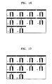
- FIG. 16 shows photographs of a process of droplet ejection using the droplet printing apparatus described with respect to FIG. 14 .
- the photographs were taken every 1/30 seconds.
- a droplet is ejected just before taking the photograph [3].
- the capillary nozzle 10 is formed of a transparent glass, and thus, a minute movement of the surface of the solution at the front-end part of the capillary nozzle can be observed.
- the concave surface of water in the photographs [1] and [2] changes to a convex shape in the photographs [3] and [4] when a droplet is ejected and then, returns to a concave shape as illustrated in the subsequent photographs.
- 26 nl of solution is ejected and the water surface of the photograph [10] returns to a state as in the photograph [1] where a droplet is not yet ejected.
- FIG. 17 shows photographs of a process of a droplet ejection to be closed to the droplets dried using the apparatus of FIG. 14 . As in FIG. 16 , the photographs were taken every 1/30 seconds. After the droplets ejected are dried in the experiment of FIG. 16, FIG. 17 shows a process of a new droplet ejection where the dried droplets are disposed in 1 mm away therefrom. Here, droplets are normally ejected without affected by the droplets already placed on the target member. Such process can improve a degree of integration when manufacturing biochips such as a DNA chip.
- the droplet printing apparatus using electric charge concentration can eject at short time intervals significantly small sized droplets, the droplets having a constant size. Also, the apparatus can be miniaturized and be operated only with a voltage supplier without using other pressure application equipment. Thus, the apparatus can be easily transported and installation thereof is easy.
- the apparatus improves an integration degree and manufacture effectiveness of the biochips.
Landscapes
- Coating Apparatus (AREA)
- Particle Formation And Scattering Control In Inkjet Printers (AREA)
- Electrostatic Spraying Apparatus (AREA)
Description
- The present invention relates to a droplet printing apparatus using capillary electric charge concentration, and more particularly, to a droplet printing apparatus using capillary electric charge concentration to stably supply using a capillary force a solution to be ejected to a nozzle.
- A droplet printing apparatus is used to eject very small droplet units of a solution on a substrate or paper. There are various droplet ejection methods. In an ink jet method, heat is supplied to a solution (ink) that is then ejected on a piece of paper or other material. However, this method is not appropriate when the characteristic of a solution to be ejected changes with heat. In particular, when a solution droplet including a biomolecule such as a nucleic acid, a protein, a living cell, a virus, or bacteria has to be ejected to manufacture a biochip, a droplet printing apparatus by which a solution can be ejected without heating is required.
- An example of such apparatus is an apparatus ejecting picoliter-sized droplets using ultrasonic energy.
-
EP 0780229 A1 andEP 1623832 A2 disclose electrostatic inkjet printheads in which ink ejection openings are provided with ejection electrodes and ink guides, respectively, which have a conical tip and protrude through the openings. -
GB 729,842 - According to an aspect of the present invention, there is provided a droplet printing apparatus which uses capillary electric charge concentration for manufacturing a biochip, the apparatus comprising: a reservoir which contains a solution comprising a biomolecule; a capillary nozzle in fluid communication with the solution contained in the reservoir; and an open circuit type voltage supplier arranged to supply a voltage to the solution, wherein the apparatus is characterized in that a the capillary nozzle is a capillary tube, a back-end part of which is immersed in the solution contained in the reservoir and a front-end part of which is exposed outside of the solution contained in the reservoir, the capillary nozzle being arranged to transmit the solution to the front-end part by a capillary force.
- The capillary nozzle may be disposed in a vertical upward direction in the reservoir. Also, the capillary nozzle may be formed of a conductive material or a non-conductive material. When the capillary nozzle is formed of a non-conductive material, a conductive material layer may be further included in an inner wall of the capillary nozzle.
- The open circuit type voltage supplier may supply a voltage to the solution through an electrode immersed in the solution contained in the reservoir. In addition, an inner wall of the capillary nozzle may be hydrophilic and a hydrophobic coating layer may be further included in the front-end part of the capillary nozzle. The inner wall of the capillary nozzle may be also hydrophobic and a hydrophilic coating layer may be further included in the front-end part of the capillary nozzle. The former case is suitable when a solvent of the solution to be ejected is a polar solvent and the latter case is suitable when a solvent of the solution to be ejected is a non-polar solvent.
- Moreover, a plurality of capillary nozzles may be disposed in the reservoir.
- According to another aspect of the present invention, there is provided a droplet printing apparatus using capillary electric charge concentration for manufacturing a biochip, comprising: a plurality of droplet printing modules arranged two-dimensionally; and a target member on which droplets ejected from each of the droplet printing modules are placed in a predetermined pattern, wherein each of the droplet printing modules comprises the droplet printing apparatus described above.
- The solutions in the reservoirs of the droplet printing modules may have different concentrations. Various patterns of droplets can be formed according to an arrangement pattern of the droplet printing modules.
- The capillary nozzle may be disposed in a vertical upward direction in the reservoir. Also, the capillary nozzle may be formed of a conductive material or a non-conductive material. When the capillary nozzle is formed of a non-conductive material, a conductive material layer may be further included in an inner wall of the capillary nozzle.
- The open circuit type voltage supplier may supply a voltage to the solution through an electrode immersed in the solution contained in the reservoir.
- In addition, the inner wall of the capillary nozzle may be hydrophilic and a hydrophobic coating layer may be further included in the front-end part of the capillary nozzle. The inner wall of the capillary nozzle may be also hydrophobic and a hydrophilic coating layer may be further included in the front-end part of the capillary nozzle. The former case is suitable when a solvent of the solution to be ejected is a polar solvent and the latter case is suitable when a solvent of the solution to be ejected is a non-polar solvent. Moreover, a plurality of capillary nozzles may be disposed in one reservoir and the open circuit type voltage supplier may supply a voltage to the solution through an electrode immersed in the solution contained in the reservoir.
- The present invention provides a droplet printing apparatus that can eject significantly small-sized droplets through a nozzle at short intervals while maintaining constant the size of droplets and can be miniaturized.
- The present invention also provides a droplet printing apparatus which improves a degree of integration of biochips and manufacture effectiveness thereof when the apparatus is used to manufacture biochips.
- The above and other features and advantages of the present invention will become more apparent by describing in detail exemplary embodiments thereof with reference to the attached drawings in which:
-
FIG. 1 is a view schematically illustrating a droplet printing apparatus according to an embodiment of the present invention; -
FIG. 2 is a view schematically illustrating a droplet printing apparatus according to another embodiment of the present invention, in a state where a voltage is supplied to a solution through an electrode immersed in the solution; -
FIG. 3 is a view schematically illustrating a droplet printing apparatus including two capillary nozzles placed in a reservoir, according to another embodiment of the present invention; -
FIG. 4 shows a cross-sectional view and a plane view of the capillary nozzle ofFIGS. 1 and3 according to an embodiment of the present invention; -
FIG. 5 shows a cross-sectional view and a plane view of a capillary nozzle having a conductive material layer included in an inner wall thereof, according to an embodiment of the present invention; -
FIG. 6 shows a cross-sectional view and a plane view of a capillary nozzle having a coating layer included in a front-end part thereof; -
FIG. 7 is a conceptual view of a transportation principle due to a capillary force in a capillary nozzle; -
FIG. 8 is a perspective view schematically illustrating a droplet printing apparatus having a plurality of capillary nozzles disposed in a reservoir according to an embodiment of the present invention; -
FIG. 9 is a perspective view schematically illustrating a droplet printing apparatus including a plurality of printing modules according to an embodiment of the present invention; -
FIG. 10A is a graph showing a volume of droplet ejected repeatedly using the apparatus ofFIG. 1 having a SUS capillary nozzle; -
FIG. 10B is a graph showing a frequency distribution chart of the droplet volume ofFIG. 10A ; -
FIG. 11 shows photographs of droplets ejected repeatedly using the apparatus ofFIG. 1 ; -
FIG. 12 shows photographs of droplets ejected repeatedly using the apparatus ofFIG. 2 ; -
FIG. 13 shows photographs of a process of droplet ejection using the apparatus ofFIG. 3 ; -
FIG. 14 is a photograph showing a front-end part of a glass capillary nozzle in a droplet printing apparatus according to an embodiment of the present invention; -
FIG. 15 is a graph showing a waveform of a voltage supplied by an open circuit type voltage supplier of the apparatus ofFIG. 14 ; -
FIG. 16 is photographs showing a process of droplet ejection using the apparatus ofFIG. 14 ; and -
FIG. 17 shows photographs of a process of a droplet ejection to be closed to the droplets dried using the apparatus ofFIG. 14 . - Hereinafter, the present invention will be described more fully with reference to the accompanying drawings, in which exemplary embodiments of the invention are shown. The invention may, however, be embodied in many different forms and should not be construed as being limited to the embodiments set forth herein; rather, these embodiments are provided so that this disclosure will be thorough and complete, and will fully convey the concept of the invention to those skilled in the art.
-
FIG. 1 is a view schematically illustrating adroplet printing apparatus 101 according to an embodiment of the present invention. - In an embodiment of the present invention, the
droplet printing apparatus 101 includes areservoir 20 containing asolution 25, acapillary nozzle 10, a back-end part of which is immersed in thesolution 25 to transmit thesolution 25 to a front-end part of thecapillary nozzle 10 by a capillary force, atarget member 30 spaced apart from the front-end part of thecapillary nozzle 10 at a predetermined distance, and an open circuittype voltage supplier 40 which supplies a voltage to thesolution 25. When an electric charge is concentrated on the surface of thesolution 25 gathered on thecapillary nozzle 10, an opposite electric charge is induced to the surface of thetarget member 30 which faces thecapillary nozzle 10, and thus, a Coulomb force between the electric charges becomes stronger than the surface tension at the surface of thesolution 25. Here, the predetermined distance refers to a distance from which a droplet can be ejected to thetarget member 30. Therefore, the predetermined distance varies according to the amplitude of a supplied voltage, an electrolyte concentration of thesolution 25, the surface tension at the surface of thesolution 25, and the like. - As illustrated in
FIG. 1 , thecapillary nozzle 10 can be disposed in a vertical upward direction in thereservoir 20 such that the front-end part of thecapillary nozzle 10 is not immersed in thesolution 25. Also, thetarget member 30 is disposed above the front-end part of thecapillary nozzle 10. However, thecapillary nozzle 10 can be also disposed slightly inclined or in a horizontal or vertical downward direction. When thecapillary nozzle 10 is disposed in a vertical upward direction, the height of thecapillary nozzle 10 exposed above the surface of thesolution 25 can be determined to be in a range corresponding to a capillary force strong enough to lift thesolution 25 in thecapillary nozzle 10. - The
capillary nozzle 10 can be formed of a conductive material such as a metal, for example, gold, platinum, copper, or aluminum, or a conductive polymer. When thecapillary nozzle 10 is formed of a conductive material, a voltage can be supplied to thesolution 25 from the open circuittype voltage supplier 40 via alead line 41 directly connected to thecapillary nozzle 10. In addition, thecapillary nozzle 10 can be formed of a non-conductive material, in which case thecapillary nozzle 10 comprises a conductive material layer in an inner wall (refer toFIG. 5 ). In this case, a voltage can also be supplied to thesolution 25 from the open circuittype voltage supplier 40 via thelead line 41 directly connected to the conductive material layer in the inner wall of thecapillary nozzle 10. - When the
droplet printing apparatus 101 is used to manufacture a biochip or a DNA microarray, thetarget member 30 may be a composite substrate formed of at least one material or two materials selected from the group consisting of silicon, glass, and polymer, but not limited thereto. Other materials can be used to form thetarget member 30 according to the use of thedroplet printing apparatus 101. Droplets of thesolution 25 ejected from the front-end part of thecapillary nozzle 10 are attached to the surface of thetarget member 30. The surface of thetarget member 30 is coated with at least one material or two materials selected from the group consisting of an amine group, a carboxyl group, streptavidine, biotin, thiol, and Poly-L-Lysine, and thus, the adhesion of biomolecules included in the droplets to thetarget member 30 can be improved. - Moreover, the
target member 30 may be a transparent substrate. If thetarget member 30 is transparent, droplets printed on the opposite side of thecapillary nozzle 10 can be optically detected. Thetarget member 30 can be also connected to ground. - The open circuit
type voltage supplier 40 is electrically connected to the inner wall of thecapillary nozzle 10. A voltage having a predetermined waveform can be supplied to thecapillary nozzle 10 from the open circuittype voltage supplier 40 via thelead line 41. The voltage can be an AC voltage or a DC voltage and the predetermined waveform can be a sine wave, a triangular wave, or a waveform obtained by overlapping at least two waveforms. The waveform and strength of the supplied voltage may vary according to the size of droplets and a property of thesolution 25. Thus, thesolution 25 contained in thecapillary nozzle 10 is electrically charged by the voltage supplied from the open circuittype voltage supplier 40. - An operating process of the
droplet printing apparatus 101 according to an embodiment of the present invention will now be described. - The
solution 25 contained in thereservoir 20 is transmitted by a capillary force from the back-end part of thecapillary nozzle 10 immersed in thesolution 25 to the front-end part of thecapillary nozzle 10 exposed outside of thesolution 25. - The
solution 25 which reaches the front-end part of thecapillary nozzle 10 and gathers thereon instead of overflowing due to a surface tension. The shape of thesolution 25 gathered on thecapillary nozzle 10 has various forms according to a contact angle of thecapillary nozzle 10 with thesolution 25. When the voltage is supplied to thesolution 25 by the open circuittype voltage supplier 40, an electric charge is concentrated on the surface ofsolution 25 which gathers on the front-end part of thecapillary nozzle 10, while an opposite electric charge is induced on the surface of thetarget member 30, which is adjacent to thecapillary nozzle 10. In this case, when a van der Waals force, which occurs between the surface of thesolution 25 on the front-end part of thecapillary nozzle 10 and thetarget member 30, that is, a Coulomb force, is stronger than the surface tension of thesolution 25, droplets are ejected towards thetarget member 30. The ejected droplets have a picoliter or nanoliter-volume, and thus, the influence of gravity can be ignored. An operation principle of thedroplet printing apparatus 101 using capillary electric charge concentration is briefly described herein. -
FIG. 2 is a view schematically illustrating adroplet printing apparatus 102 according to another embodiment of the present invention, in a state where a voltage is supplied to a solution through an electrode (not shown) immersed in the solution. - The
droplet printing apparatus 102 is almost the same with thedroplet printing apparatus 101 described above. The only difference is that the open circuittype voltage supplier 40 supplies a voltage via alead line 43 to the electrode immersed in asolution 25 contained in areservoir 20. The electrode can be formed of various materials, and may also be an end part of thelead line 43 from which coating is removed. In an embodiment of the present invention, acapillary nozzle 10 may be formed of a conductive material or a non-conductive material. -
FIG. 3 is a view schematically illustrating adroplet printing apparatus 103 including twocapillary nozzles 10 placed in a reservoir according to another embodiment of the present invention. Although only twocapillary nozzles 10 are shown inFIG. 3 , more than twocapillary nozzles 10 may be used. - The
droplet printing apparatus 103 is almost the same with thedroplet printing apparatus 102 described above. The only difference is that twocapillary nozzles 10 are disposed in thereservoir 20. Since, the open circuittype voltage supplier 40 supplies a voltage to asolution 25 contained in thereservoir 20 through soaked electrode instead of thecapillary nozzles 10, droplets can be ejected from a number ofcapillary nozzles 10 without wiring each of thecapillary nozzles 10. -
FIG. 4 shows a cross-sectional view and a plane view of thecapillary nozzle 10 according to an embodiment of the present invention. Thecapillary nozzle 10 is in the form of a capillary tube. Awall 15 of thecapillary nozzle 10 may be formed of a conductive material or a non-conductive material. The conductive material may be a metal that has an anti-corrosive property against thesolution 25 to be ejected. The non-conductive material may be glass or a plastic material. -
Fig. 5 shows a cross-sectional view and a plane view of acapillary nozzle 11 having aconductive material layer 16 included in an inner wall thereof, according to an embodiment of the present invention. For example, awall 15 of thecapillary nozzle 11 is formed of glass and theconductive material layer 16 may be an ITO (Indium Tin Oxide) layer. In this case, theconductive material layer 16 can be connected to the open circuittype voltage supplier 40 via the lead line. -
FIG. 6 shows a cross-sectional view and a plane view of acapillary nozzle 12 having acoating layer 17 included in a front-end part thereof. Thecoating layer 17 may be further included in the inner surface of the front-end part of awall 15 of thecapillary nozzle 12. Thecoating layer 17 may be a hydrophobic coating layer if thesolution 25 is an aqueous solution. In this case, thecoating layer 17 may be formed, for example, of a material having low hydrophilicity with respect to the inner surface of thewall 15 of the front-end part of thecapillary nozzle 12. Therefore, thecoating layer 17 increases or reduces a contact angle at the front-end part of thecapillary nozzle 12 according to the material property thereof and thus droplets can form in the front-end part of thecapillary nozzle 12 with an appropriate size to be ejected. -
FIG. 7 is a conceptual view of a transportation principle due to a capillary force in a capillary nozzle. Gravity (Fg) and a capillary force (Fc) act in the capillary nozzle. When the capillary nozzle is disposed in a vertical upward direction, the gravity (Fg) and capillary force (Fc) occur at a predetermined height (H) in opposite directions. The height (H) is the maximum height at which the solution can be transmitted using the capillary force (Fc). The height of the capillary nozzle of the droplet printing apparatus according to the present invention is lower than the maximum height so that when droplets are ejected from the front-end part of the capillary nozzle the amount of solution corresponding to the volume of the droplets ejected can be immediately and stably supplemented. Since the solution is supplied to the front-end part of the capillary nozzle via the capillary force (Fc), the surface of the solution, immediately after the droplets are ejected, can be stabilized promptly and thus, the repeatability of the droplet printing apparatus can be greatly improved. - If the inner radius, a contact angle of the solution with the inner wall, the surface tension per the unit length, and the density of the solution are R, θ, γ, and ρ, respectively, the maximum height H of the solution in the capillary nozzle when the gravity Fg and the capillary force Fc are parallel is H = 2γcosθ/ρgR (g is the gravitational acceleration).
- For example, in a DNA solution having a concentration of 20 µM (γ=58.2dyn/cm2, θ=40°, ρ=1.01g/cm3), when the inner radius R of the capillary nozzles is 0.0115cm, H is approximately 7.4cm. Therefore, if the height of the capillary nozzles measured from the surface of the solution is equal to or less than 7.4 cm, the solution can be supplied to the front-end part of the capillary nozzles.
-
FIG. 8 is a perspective view schematically illustrating adroplet printing apparatus 104 having a plurality ofcapillary nozzles 10 disposed in onereservoir 20 according to an embodiment of the present invention. Thecapillary nozzles 10 can be disposed in any desired pattern in thereservoir 20. According to the arrangement of thecapillary nozzles 10,droplets 27 ejected from thecapillary nozzles 10 and seated on thetarget member 30 form a regular pattern. Thereservoir 20 includes aninlet hole 21 and anoutlet hole 22, for respectively receiving and discharging a solution, and alead line 43 connected to an open circuittype voltage supplier 40 can be electrically connected to the solution contained in thereservoir 20, for example, through theoutlet hole 22. In more detail, thelead line 43 can be connected to an electrode (not illustrated) immersed in the solution contained in thereservoir 20. The electrode can be formed of any materials having an anti-corrosive property against the solution. In addition, in order to uniformly eject thedroplets 27 from thecapillary nozzles 10, distances between the electrode and the front-end part of each of thecapillary nozzles 10 should be equal to one another. Thecapillary nozzles 10 can be also formed of insulating materials. In this case, an electrical interaction between thecapillary nozzles 10 is decreased and thus, integration of the capillary nozzles is possible. -
FIG. 9 is a perspective view schematically illustrating adroplet printing apparatus 105 including a plurality of printing modules according to an embodiment of the present invention. The droplet printing modules are arranged two-dimensionally.Droplets 27 or 27' are ejected from each of the droplet printing modules on atarget member 30 in a predetermined pattern. Each of the droplet printing modules includes areservoir 20 or 20', containing a solution to be ejected, and acapillary nozzle 10, a back-end part of which is immersed in the solution contained in thereservoir 20 or 20', a front-end part of which is spaced apart from thetarget member 30 at a predetermined distance, wherein he back-end part transmits the solution to the front-end part of thecapillary nozzle 10 by a capillary force, and an open circuit type voltage supplier (not illustrated) which supplies a voltage to the solution. Thereservoirs 20 and 20' may contain different kinds of solutions or solutions of different concentrations, if necessary. In this case, the droplet 27' is different from thedroplet 27. - Each of the
reservoirs 20 and 20' have aninlet hole 21 and anoutlet hole 22. The open circuit type voltage supplier (not illustrated) may supply a voltage through an inner wall of thecapillary nozzle 10 as in thedroplet printing apparatus 101 ofFIG. 1 or through an electrode (not illustrated) immersed in the solution contained in thereservoir 20 as in thedroplet printing apparatus 102 ofFIG. 2 . -
FIG. 10A is a graph showing a volume of droplet ejected repeatedly using the apparatus ofFIG. 1 having a SUS capillary nozzle. The droplet printing apparatus used in the experiment includes capillary nozzles formed of SUS and a target member formed of a glass. The distance between the front-end part of thecapillary nozzles 10 and thetarget member 30 is 200 µm and a voltage is supplied at an interval of 3.5 seconds and droplet ejection is repeatedly performed 80 times. As indicated inFIG. 10A , the average volume is 33 pL. -
FIG. 10B is a graph showing a frequency distribution chart of the droplet volumes ofFIG. 10A . As shown inFIG. 10B , when droplet ejection is performed repeatedly 80 times, the average volume of the droplet is 33 pl. and the standard deviation is 5.3, which mean an ejection reliability of 95 %. -
FIG. 11 shows photographs of droplets ejected repeatedly using the apparatus ofFIG. 1 . - Referring to
FIG. 11 , a droplet is ejected 7 times at a 3 second interval using the apparatus used in the experiment described with respect toFIG. 10A . The open circuit type voltage supplier is directly connected to thecapillary nozzle 10 to supply the voltage. The lower parts of the photographs show the front-end part of thecapillary nozzle 10 and a convex surface at the front-end part of thecapillary nozzle 10 is the surface of the solution. The upper part of the photographs show the target member formed of a glass and each droplet is attached to the bottom surface of the target member. As shown in the photographs, the droplets have regular sizes. -
FIG. 12 shows photographs of droplets ejected repeatedly using the apparatus ofFIG. 2 - Unlike the experiment of
FIG. 11 , the open circuit type voltage supplier supplies the voltage through the electrode immersed in the solution contained in thereservoir 20. In this case, the volume of the droplet is bigger than inFIG. 11 . However, after droplet ejections are repeatedly performed 7 times, the volumes of the droplets become regular. -
FIG. 13 shows photographs of a process of droplet ejection using the apparatus ofFIG. 3 . The lower parts of the photograph show thecapillary nozzle 10 and the upper parts of the photograph show a reflection of the capillary nozzle from the glass substrate. Two capillary nozzles are disposed at an interval of 3 mm. After the voltage is supplied to the electrode immersed in thesolution 25, picoliter sized droplets are ejected at the same time. When thecapillary nozzles 10 are formed of a conductive material and the voltage is directly supplied thereto, noise appears between adjacent capillary nozzles and thus, there is a limitation of integrating thecapillary nozzles 10. However, when the voltage is supplied to thesolution 25 contained in the reservoir as inFIG. 13 , a plurality ofcapillary nozzles 10 can be disposed at short intervals of 3 mm. -
FIGS. 14 through 17 refer to experiments performed using a droplet printing apparatus having the structure according to the embodiment ofFIG. 2 and thecapillary nozzles 10 formed of glass. -
FIG. 14 is a photograph showing a front-end part of theglass capillary nozzle 10. The external diameter and the inside diameter of the glass capillary nozzle are 1.5 mm and 0.84 mm, respectively. Also, the height from the surface of the solution to the front-end part of the capillary nozzle is 2.57 mm. As illustrated inFIG. 14 , the distance between the front-end part of thecapillary nozzle 10 and the target member is 500 µm. -
FIG. 15 is a graph showing a waveform of a voltage supplied by an open circuit type voltage supplier of the droplet printing apparatus described with respect toFIG. 14 . The voltage waveform is a half cycle sine wave as shown inFIG. 15 . The maximum voltage is 4 kV. However, the waveform illustrated inFIG. 15 is just an example and the open circuit type voltage supplier can supply voltages having various types of waveforms such as a one cycle sine wave, a square wave, a saw wave, and combination thereof. The size of the droplet ejected can be controlled by adjusting the voltage waveform, a size of the waveform, and the frequency. When a voltage in a sine waveform is supplied, when the frequency increases, the volume of the droplet reduces and vice versa. - The frequency of the voltage supplied can be in the range of 1 through 10 kHz as necessary.
-
FIG. 16 shows photographs of a process of droplet ejection using the droplet printing apparatus described with respect toFIG. 14 . The photographs were taken every 1/30 seconds. As shown in the photographs, a droplet is ejected just before taking the photograph [3]. Thecapillary nozzle 10 is formed of a transparent glass, and thus, a minute movement of the surface of the solution at the front-end part of the capillary nozzle can be observed. - The concave surface of water in the photographs [1] and [2] changes to a convex shape in the photographs [3] and [4] when a droplet is ejected and then, returns to a concave shape as illustrated in the subsequent photographs. In such process, 26 nl of solution is ejected and the water surface of the photograph [10] returns to a state as in the photograph [1] where a droplet is not yet ejected.
-
FIG. 17 shows photographs of a process of a droplet ejection to be closed to the droplets dried using the apparatus ofFIG. 14 . As inFIG. 16 , the photographs were taken every 1/30 seconds. After the droplets ejected are dried in the experiment ofFIG. 16, FIG. 17 shows a process of a new droplet ejection where the dried droplets are disposed in 1 mm away therefrom. Here, droplets are normally ejected without affected by the droplets already placed on the target member. Such process can improve a degree of integration when manufacturing biochips such as a DNA chip. - According to the present invention, the droplet printing apparatus using electric charge concentration can eject at short time intervals significantly small sized droplets, the droplets having a constant size. Also, the apparatus can be miniaturized and be operated only with a voltage supplier without using other pressure application equipment. Thus, the apparatus can be easily transported and installation thereof is easy.
- Moreover, when the droplet printing apparatus according to the present invention is used to manufacture biochips, the apparatus improves an integration degree and manufacture effectiveness of the biochips.
- While the present invention has been particularly shown and described with reference to exemplary embodiments thereof, it will be understood by those of ordinary skill in the art that various changes in form and details may be made therein without departing from the scope of the present invention as defined by the following claims.
Claims (13)
- A droplet printing apparatus which uses capillary electric charge concentration for manufacturing a biochip, the apparatus comprising:a reservoir (20) which contains a solution (25) comprising a biomolecule;a capillary nozzle (10) in fluid communication with the solution (25) contained in the reservoir (20); andan open circuit type voltage supplier (40) arranged to supply a voltage to the solution (25),wherein the apparatus is characterized in that the capillary nozzle (10) is a capillary tube, a back-end part of which is immersed in the solution (25) contained in the reservoir (20) and a front-end part of which is exposed outside of the solution (25) contained in the reservoir (20), the capillary nozzle (10) being arranged to transmit the solution (25) to the front-end part by a capillary force.
- The droplet printing apparatus of claim 1, wherein the capillary nozzle (10) is disposed in a vertical upward direction in the reservoir (20).
- The droplet printing apparatus of claim 1 or 2, wherein the capillary nozzle (10) is formed of a conductive material.
- The droplet printing apparatus of claim 3, wherein the open circuit type voltage supplier (40) is arranged to supply a voltage to the capillary nozzle (10).
- The droplet printing apparatus of claim 1 or 2, wherein the capillary nozzle (10) is formed of a non-conductive material (15) and further includes a conductive material layer (16) in an inner wall thereof.
- The droplet printing apparatus of claim 5, wherein the open circuit type voltage supplier (40) is arranged to supply a voltage to the conductive material layer (16).
- The droplet printing apparatus of claim 1 or 2, wherein the capillary nozzle (10) is formed of a non-conductive material.
- The droplet printing apparatus of claim 7, wherein the open circuit type voltage supplier (40) is arranged to supply a voltage to the solution (25) through an electrode immersed in the solution (25) contained in the reservoir (20).
- The droplet printing apparatus of any preceding claim, wherein an inner wall of the capillary nozzle (10) is hydrophilic and a hydrophobic coating layer is further included in the front-end part of the capillary nozzle (10).
- The droplet printing apparatus of any of claims 1 to 8, wherein an inner wall of the capillary nozzle (10) is hydrophobic and a hydrophilic coating layer is further included in the front-end part of the capillary nozzle (10).
- The droplet printing apparatus of claim 1, wherein a plurality of capillary nozzles (10) are disposed in one reservoir (20) and the open circuit type voltage supplier (40) is arranged to supply a voltage to the solution (25) through an electrode immersed in the solution (25) contained in the reservoir (20).
- The droplet printing apparatus of any preceding claim, further comprising a target member (30) spaced apart from the front-end part of the capillary nozzle (10) by a predetermined distance.
- A droplet printing apparatus using capillary electric charge concentration for manufacturing a biochip, comprising:a plurality of droplet printing modules arranged two-dimensionally; anda target member (30) on which droplets ejected from each of the droplet printing modules are placed in a predetermined pattern, wherein each of the droplet printing modules comprises the droplet printing apparatus of any of claims 1 to 11.
Applications Claiming Priority (1)
| Application Number | Priority Date | Filing Date | Title |
|---|---|---|---|
| KR1020060041964A KR101316751B1 (en) | 2006-05-10 | 2006-05-10 | Liquid droplet printing device using capillary electric charge concentration method |
Publications (3)
| Publication Number | Publication Date |
|---|---|
| EP1854631A2 EP1854631A2 (en) | 2007-11-14 |
| EP1854631A3 EP1854631A3 (en) | 2008-07-02 |
| EP1854631B1 true EP1854631B1 (en) | 2011-04-06 |
Family
ID=38326283
Family Applications (1)
| Application Number | Title | Priority Date | Filing Date |
|---|---|---|---|
| EP06123329A Ceased EP1854631B1 (en) | 2006-05-10 | 2006-11-01 | Electrostatic printing apparatus using electric charge concentration at the ejection nozzle opening of a capillary |
Country Status (5)
| Country | Link |
|---|---|
| US (1) | US7794054B2 (en) |
| EP (1) | EP1854631B1 (en) |
| JP (1) | JP2007301992A (en) |
| KR (1) | KR101316751B1 (en) |
| DE (1) | DE602006021153D1 (en) |
Families Citing this family (2)
| Publication number | Priority date | Publication date | Assignee | Title |
|---|---|---|---|---|
| US8469492B2 (en) * | 2006-05-10 | 2013-06-25 | Samsung Electronics Co., Ltd. | Method of printing droplet using capillary electric charge concentration |
| JP5266132B2 (en) | 2009-05-15 | 2013-08-21 | 住友ゴム工業株式会社 | Pneumatic tire |
Family Cites Families (11)
| Publication number | Priority date | Publication date | Assignee | Title |
|---|---|---|---|---|
| DE957635C (en) | 1952-01-30 | 1957-01-17 | LICENTIA Patent-Verwaltungs-G mbH, Hamburg | Method and device for producing coatings in an electrostatic field, in which the atomization also takes place electrostatically |
| DE2105373B2 (en) * | 1971-02-05 | 1972-12-28 | Olympia Werke Ag, 2940 Wilhelmshaven | DEVICE FOR GENERATING A VISIBLE PRINTED IMAGE BY TRANSFERRING INK DROPS |
| US3911448A (en) * | 1972-11-22 | 1975-10-07 | Ohno Res & Dev Lab | Plural liquid recording elements |
| JP2783230B2 (en) * | 1995-12-18 | 1998-08-06 | 日本電気株式会社 | Electrostatic ink jet recording head |
| US6879162B2 (en) * | 2000-11-07 | 2005-04-12 | Sri International | System and method of micro-fluidic handling and dispensing using micro-nozzle structures |
| US7520592B2 (en) | 2002-09-24 | 2009-04-21 | Sharp Kabushiki Kaisha | Electrostatic attraction fluid jet device |
| KR100552705B1 (en) | 2004-01-07 | 2006-02-20 | 삼성전자주식회사 | Apparatus for printing biomolecules on a substrate using an electrohydraulic phenomenon and a method of printing the same |
| JP2006043936A (en) | 2004-08-02 | 2006-02-16 | Fuji Photo Film Co Ltd | Liquid ejection head and its manufacturing process |
| KR20050074496A (en) | 2005-04-22 | 2005-07-18 | 노키아 코포레이션 | Validation of beacon signals |
| KR100668343B1 (en) | 2005-08-12 | 2007-01-12 | 삼성전자주식회사 | Apparatus for printing biomolecule droplets on a substrate using an electric charge concentration phenomenon, and Apparatus for printing ink on a printing paper or a printed substrate using an electric charge concentration phenomenon |
| KR100723425B1 (en) | 2006-04-13 | 2007-05-30 | 삼성전자주식회사 | Apparatus and method for printing biomolecule droplets on a substrate |
-
2006
- 2006-05-10 KR KR1020060041964A patent/KR101316751B1/en not_active Expired - Fee Related
- 2006-11-01 DE DE602006021153T patent/DE602006021153D1/en active Active
- 2006-11-01 EP EP06123329A patent/EP1854631B1/en not_active Ceased
-
2007
- 2007-04-24 JP JP2007114482A patent/JP2007301992A/en active Pending
- 2007-05-09 US US11/746,299 patent/US7794054B2/en not_active Expired - Fee Related
Also Published As
| Publication number | Publication date |
|---|---|
| EP1854631A2 (en) | 2007-11-14 |
| US20080316261A1 (en) | 2008-12-25 |
| EP1854631A3 (en) | 2008-07-02 |
| DE602006021153D1 (en) | 2011-05-19 |
| KR20070109243A (en) | 2007-11-15 |
| JP2007301992A (en) | 2007-11-22 |
| KR101316751B1 (en) | 2013-10-08 |
| US7794054B2 (en) | 2010-09-14 |
Similar Documents
| Publication | Publication Date | Title |
|---|---|---|
| KR20090081882A (en) | Droplet ejection apparatus having a piezoelectric voltage generator, and a droplet ejection method using the same | |
| US7481511B2 (en) | Droplet dispensation from a reservoir with reduction in uncontrolled electrostatic charge | |
| US10118186B2 (en) | Avoidance of bouncing and splashing in droplet-based fluid transport | |
| CN101663097B (en) | Micromachined fluid ejector | |
| US6603118B2 (en) | Acoustic sample introduction for mass spectrometric analysis | |
| JP4128336B2 (en) | Dual manifold system and liquid parallel transfer method | |
| EP1880769B1 (en) | Electric charge concentration type droplet dispensing device having nonconductive capillary nozzle | |
| US7600849B2 (en) | Method and apparatus for scalable droplet ejection manufacturing | |
| US7910379B2 (en) | Apparatus and method for ejecting droplets using charge concentration and liquid bridge breakup | |
| US8469492B2 (en) | Method of printing droplet using capillary electric charge concentration | |
| US7794054B2 (en) | Droplet printing apparatus using capillary electric charge concentration | |
| CN101024336A (en) | Method and apparatus for printing liquid droplets of biological molecules on substrate by utilizing charge concentration effect | |
| WO2006088282A1 (en) | Apparatus and method for jetting droplets using electrostatic field | |
| KR100871342B1 (en) | Roll-to-Roll Printing Device and Printing Method | |
| US10343398B2 (en) | System and method for creating a pico-fluidic inkjet | |
| EP1585636B1 (en) | Droplet dispensation from a reservoir with reduction in uncontrolled electrostatic charge |
Legal Events
| Date | Code | Title | Description |
|---|---|---|---|
| PUAI | Public reference made under article 153(3) epc to a published international application that has entered the european phase |
Free format text: ORIGINAL CODE: 0009012 |
|
| AK | Designated contracting states |
Kind code of ref document: A2 Designated state(s): AT BE BG CH CY CZ DE DK EE ES FI FR GB GR HU IE IS IT LI LT LU LV MC NL PL PT RO SE SI SK TR |
|
| AX | Request for extension of the european patent |
Extension state: AL BA HR MK YU |
|
| PUAL | Search report despatched |
Free format text: ORIGINAL CODE: 0009013 |
|
| AK | Designated contracting states |
Kind code of ref document: A3 Designated state(s): AT BE BG CH CY CZ DE DK EE ES FI FR GB GR HU IE IS IT LI LT LU LV MC NL PL PT RO SE SI SK TR |
|
| AX | Request for extension of the european patent |
Extension state: AL BA HR MK RS |
|
| 17P | Request for examination filed |
Effective date: 20081210 |
|
| 17Q | First examination report despatched |
Effective date: 20090113 |
|
| AKX | Designation fees paid |
Designated state(s): DE GB |
|
| GRAP | Despatch of communication of intention to grant a patent |
Free format text: ORIGINAL CODE: EPIDOSNIGR1 |
|
| GRAS | Grant fee paid |
Free format text: ORIGINAL CODE: EPIDOSNIGR3 |
|
| GRAA | (expected) grant |
Free format text: ORIGINAL CODE: 0009210 |
|
| AK | Designated contracting states |
Kind code of ref document: B1 Designated state(s): DE GB |
|
| REG | Reference to a national code |
Ref country code: GB Ref legal event code: FG4D |
|
| REF | Corresponds to: |
Ref document number: 602006021153 Country of ref document: DE Date of ref document: 20110519 Kind code of ref document: P |
|
| REG | Reference to a national code |
Ref country code: DE Ref legal event code: R096 Ref document number: 602006021153 Country of ref document: DE Effective date: 20110519 |
|
| PLBE | No opposition filed within time limit |
Free format text: ORIGINAL CODE: 0009261 |
|
| STAA | Information on the status of an ep patent application or granted ep patent |
Free format text: STATUS: NO OPPOSITION FILED WITHIN TIME LIMIT |
|
| 26N | No opposition filed |
Effective date: 20120110 |
|
| REG | Reference to a national code |
Ref country code: DE Ref legal event code: R097 Ref document number: 602006021153 Country of ref document: DE Effective date: 20120110 |
|
| PGFP | Annual fee paid to national office [announced via postgrant information from national office to epo] |
Ref country code: DE Payment date: 20181023 Year of fee payment: 13 |
|
| PGFP | Annual fee paid to national office [announced via postgrant information from national office to epo] |
Ref country code: GB Payment date: 20181031 Year of fee payment: 13 |
|
| REG | Reference to a national code |
Ref country code: DE Ref legal event code: R119 Ref document number: 602006021153 Country of ref document: DE |
|
| GBPC | Gb: european patent ceased through non-payment of renewal fee |
Effective date: 20191101 |
|
| PG25 | Lapsed in a contracting state [announced via postgrant information from national office to epo] |
Ref country code: DE Free format text: LAPSE BECAUSE OF NON-PAYMENT OF DUE FEES Effective date: 20200603 Ref country code: GB Free format text: LAPSE BECAUSE OF NON-PAYMENT OF DUE FEES Effective date: 20191101 |