EP1854527A1 - Fuel filter assembly - Google Patents
Fuel filter assembly Download PDFInfo
- Publication number
- EP1854527A1 EP1854527A1 EP06291307A EP06291307A EP1854527A1 EP 1854527 A1 EP1854527 A1 EP 1854527A1 EP 06291307 A EP06291307 A EP 06291307A EP 06291307 A EP06291307 A EP 06291307A EP 1854527 A1 EP1854527 A1 EP 1854527A1
- Authority
- EP
- European Patent Office
- Prior art keywords
- cover plate
- fuel
- housing
- fuel filter
- chamber
- Prior art date
- Legal status (The legal status is an assumption and is not a legal conclusion. Google has not performed a legal analysis and makes no representation as to the accuracy of the status listed.)
- Granted
Links
Images
Classifications
-
- B—PERFORMING OPERATIONS; TRANSPORTING
- B01—PHYSICAL OR CHEMICAL PROCESSES OR APPARATUS IN GENERAL
- B01D—SEPARATION
- B01D35/00—Filtering devices having features not specifically covered by groups B01D24/00 - B01D33/00, or for applications not specifically covered by groups B01D24/00 - B01D33/00; Auxiliary devices for filtration; Filter housing constructions
- B01D35/18—Heating or cooling the filters
-
- B—PERFORMING OPERATIONS; TRANSPORTING
- B01—PHYSICAL OR CHEMICAL PROCESSES OR APPARATUS IN GENERAL
- B01D—SEPARATION
- B01D2201/00—Details relating to filtering apparatus
- B01D2201/30—Filter housing constructions
- B01D2201/301—Details of removable closures, lids, caps, filter heads
- B01D2201/302—Details of removable closures, lids, caps, filter heads having inlet or outlet ports
Definitions
- the present invention relates to a fuel filter assembly having an integral electrical heater.
- a fuel filter assembly in accordance with the present invention comprises a filter housing having an open end; a cover plate for sealably closing the open end of the housing; a filter cartridge positioned inside the housing and having a surface positioned adjacent the cover plate; a fuel inlet port mounted on the cover plate; a chamber between the cover plate and the cartridge surface, the chamber being fluidly connected with the fuel inlet port and having an outlet for fuel flow through the filter cartridge; and an electrical heater positioned in the chamber.
- the chamber is preferably defined by walls formed in the surface of the cartridge.
- the chamber may be define by walls formed in the cover plate, or a combination of walls formed in the surface of the cartridge and the cover plate.
- the electrical heater is preferably secured to the cover plate. Alternatively, the electrical heater may be secured to the surface of the filter cartridge.
- the electrical heater is preferably part of a removable sub-assembly.
- the electrical heater is preferably in the form of a heater plate.
- the cover plate is preferably fixedly secured to the housing.
- the cover plate may be removable.
- the housing and/or the cover plate and/or the inlet port are preferably made from metallic material.
- one or more of the housing, the cover plate or the inlet port may be made from plastics material.
- the present invention provides a fuel filter assembly with an electrical heater, in which the filter housing, cover plate, and fuel inlet port may all be fabricated from metallic material when such a need arises.
- the fuel filter assembly 10 comprises a filter housing 12 having an open end; a cover plate 14 for sealably closing the open end of the housing; a filter cartridge 16 positioned inside the housing and having a surface 18 positioned adjacent the cover plate; a fuel inlet port 20 mounted on the cover plate for the flow of fuel into the filter assembly; a chamber 22 between the cover plate and the cartridge surface, the chamber being fluidly connected with the fuel inlet port and having an outlet 24 for fuel flow through the filter cartridge; and an electrical heater 26 positioned in the chamber.
- the filter assembly 10 also includes a fuel outlet port 28 for the flow of fuel out of the filter assembly after passing through the filter cartridge 16.
- the chamber 22 is defined by walls 30 formed in the surface 18 of the filter cartridge 16.
- the electrical heater 26 is secured to the cover plate 14, preferably by screws or any other suitable arrangement.
- the electrical heater 26 is part of a removable sub-assembly 32 including suitable electrical connections which can be removed when the filter assembly requires servicing or replacing.
- the electrical heater 26 is in the form of a heater plate.
- the cover plate 14 is fixedly secured to the housing 12. Alternatively, the cover plate 14 may be removable from the housing 12 to allow replacement of the filter cartridge 16.
- the housing 12, the cover plate 14, the inlet port 20, and the outlet port 28 are made from metallic material.
Landscapes
- Chemical & Material Sciences (AREA)
- Chemical Kinetics & Catalysis (AREA)
- Filtration Of Liquid (AREA)
- Lubrication Details And Ventilation Of Internal Combustion Engines (AREA)
Abstract
Description
- The present invention relates to a fuel filter assembly having an integral electrical heater.
- It is known to provide a fuel filter assembly with an electrical heater to avoid problems of "waxing", especially during cold start. There are various known designs, including a stick heater which can be screw fitted to the filter housing or bowl; or a self-contained heater which is attached to the filter housing; or an electric heater moulded into a plastics cover for the filter. With the need to increase the strength of the filter assembly, there is a desire to manufacture the filter housing, and the fuel inlet and outlet ports from metallic material. The known arrangements for an electrical heater are not suitable for such an assembly.
- It is an object of the present invention to overcome the above-mentioned problem.
- A fuel filter assembly in accordance with the present invention comprises a filter housing having an open end; a cover plate for sealably closing the open end of the housing; a filter cartridge positioned inside the housing and having a surface positioned adjacent the cover plate; a fuel inlet port mounted on the cover plate; a chamber between the cover plate and the cartridge surface, the chamber being fluidly connected with the fuel inlet port and having an outlet for fuel flow through the filter cartridge; and an electrical heater positioned in the chamber.
- The chamber is preferably defined by walls formed in the surface of the cartridge. Alternatively, the chamber may be define by walls formed in the cover plate, or a combination of walls formed in the surface of the cartridge and the cover plate.
- The electrical heater is preferably secured to the cover plate. Alternatively, the electrical heater may be secured to the surface of the filter cartridge. The electrical heater is preferably part of a removable sub-assembly. The electrical heater is preferably in the form of a heater plate.
- The cover plate is preferably fixedly secured to the housing. Alternatively, the cover plate may be removable.
- The housing and/or the cover plate and/or the inlet port are preferably made from metallic material. Alternatively, one or more of the housing, the cover plate or the inlet port may be made from plastics material.
- The present invention provides a fuel filter assembly with an electrical heater, in which the filter housing, cover plate, and fuel inlet port may all be fabricated from metallic material when such a need arises.
- The present invention will now be described, by way of example, with reference to the accompanying drawings, in which:
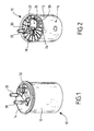
- Figure 1 is a perspective view of a fuel filter assembly in accordance with an embodiment of the present invention;
- Figure 2 is a perspective view of the assembly of Figure 1 with the cover removed; and
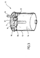
- Figure 3 is a cross-sectional view of the assembly of Figure 1 with the cartridge removed.
- Referring to the drawings, the
fuel filter assembly 10 comprises afilter housing 12 having an open end; acover plate 14 for sealably closing the open end of the housing; afilter cartridge 16 positioned inside the housing and having asurface 18 positioned adjacent the cover plate; afuel inlet port 20 mounted on the cover plate for the flow of fuel into the filter assembly; achamber 22 between the cover plate and the cartridge surface, the chamber being fluidly connected with the fuel inlet port and having anoutlet 24 for fuel flow through the filter cartridge; and anelectrical heater 26 positioned in the chamber. Thefilter assembly 10 also includes afuel outlet port 28 for the flow of fuel out of the filter assembly after passing through thefilter cartridge 16. - In this embodiment, the
chamber 22 is defined bywalls 30 formed in thesurface 18 of thefilter cartridge 16. Theelectrical heater 26 is secured to thecover plate 14, preferably by screws or any other suitable arrangement. Theelectrical heater 26 is part of aremovable sub-assembly 32 including suitable electrical connections which can be removed when the filter assembly requires servicing or replacing. Theelectrical heater 26 is in the form of a heater plate. - The
cover plate 14 is fixedly secured to thehousing 12. Alternatively, thecover plate 14 may be removable from thehousing 12 to allow replacement of thefilter cartridge 16. - The
housing 12, thecover plate 14, theinlet port 20, and theoutlet port 28 are made from metallic material.
Claims (12)
- Fuel filter assembly (10) comprising a filter housing (12) having an open end; a cover plate (14) for sealably closing the open end of the housing; a filter cartridge (16) positioned inside the housing and having a surface (18) positioned adjacent the cover plate; a fuel inlet port (20) mounted on the cover plate; a chamber (22) between the cover plate and the cartridge surface, the chamber being fluidly connected with the fuel inlet port and having an outlet (24) for fuel flow through the filter cartridge; and an electrical heater (26) positioned in the chamber.
- Fuel filter according to claim 1, wherein the chamber is defined by walls (30) formed in the surface of the cartridge.
- Fuel filter according to claim 1 or 2, wherein the chamber is defined by walls formed in the cover plate, or a combination of walls formed in the surface of the cartridge and the cover plate.
- Fuel filter according to any of claims 1 to 3, wherein the electrical heater is secured to the cover plate.
- Fuel filter according to any of claims 1 to 3, wherein the electrical heater is secured to the surface of the filter cartridge.
- Fuel filter according to any of claims 1 to 5, wherein the electrical heater is part of a removable sub-assembly (32).
- Fuel filter according to any of claims 1 to 6, wherein the electrical heater is in the form of a heater plate.
- Fuel filter according to any of claims 1 to 7, wherein the cover plate is fixedly secured to the housing.
- Fuel filter according to any of claims 1 to 7, wherein the cover plate is removable.
- Fuel filter according to any of claims 1 to 9, wherein the housing and/or the cover plate and/or the inlet port are made from metallic material.
- Fuel filter according to any of claims 1 to 10, wherein one or more of the housing, the cover plate or the inlet port are made from plastics material.
- Fuel filter according to claim 10, wherein the filter housing, cover plate, and fuel inlet port are all fabricated from metallic material.
Applications Claiming Priority (1)
| Application Number | Priority Date | Filing Date | Title |
|---|---|---|---|
| GBGB0609246.4A GB0609246D0 (en) | 2006-05-10 | 2006-05-10 | A fuel filter assembly |
Publications (2)
| Publication Number | Publication Date |
|---|---|
| EP1854527A1 true EP1854527A1 (en) | 2007-11-14 |
| EP1854527B1 EP1854527B1 (en) | 2012-01-18 |
Family
ID=36637224
Family Applications (1)
| Application Number | Title | Priority Date | Filing Date |
|---|---|---|---|
| EP06291307A Expired - Lifetime EP1854527B1 (en) | 2006-05-10 | 2006-08-11 | Fuel filter assembly |
Country Status (3)
| Country | Link |
|---|---|
| EP (1) | EP1854527B1 (en) |
| AT (1) | ATE541628T1 (en) |
| GB (1) | GB0609246D0 (en) |
Cited By (1)
| Publication number | Priority date | Publication date | Assignee | Title |
|---|---|---|---|---|
| WO2014016319A1 (en) * | 2012-07-26 | 2014-01-30 | Mahle International Gmbh | Filter device |
Citations (6)
| Publication number | Priority date | Publication date | Assignee | Title |
|---|---|---|---|---|
| EP0162939A1 (en) * | 1984-05-29 | 1985-12-04 | David + Baader DBK Spezialfabrik Elektrischer Apparate und Heizwiderstände GmbH | Fuel heater for a diesel engine |
| DE3443717A1 (en) * | 1984-11-30 | 1986-06-05 | Robert Bosch Gmbh, 7000 Stuttgart | Liquid filter |
| GB2265095A (en) * | 1992-03-18 | 1993-09-22 | Cleanburn Limited | Filter for diesel fuel |
| EP1101519A1 (en) | 1999-11-17 | 2001-05-23 | Filterwerk Mann + Hummel Gmbh | Fuel filter |
| US6328883B1 (en) | 2000-05-31 | 2001-12-11 | Parker-Hannifin Corporation | Fuel filter assembly with priming pump |
| WO2002006662A1 (en) * | 2000-07-17 | 2002-01-24 | Sogefi Filtration S.P.A. | Diesel fuel filter with interchangeable cartridge |
-
2006
- 2006-05-10 GB GBGB0609246.4A patent/GB0609246D0/en not_active Ceased
- 2006-08-11 AT AT06291307T patent/ATE541628T1/en active
- 2006-08-11 EP EP06291307A patent/EP1854527B1/en not_active Expired - Lifetime
Patent Citations (6)
| Publication number | Priority date | Publication date | Assignee | Title |
|---|---|---|---|---|
| EP0162939A1 (en) * | 1984-05-29 | 1985-12-04 | David + Baader DBK Spezialfabrik Elektrischer Apparate und Heizwiderstände GmbH | Fuel heater for a diesel engine |
| DE3443717A1 (en) * | 1984-11-30 | 1986-06-05 | Robert Bosch Gmbh, 7000 Stuttgart | Liquid filter |
| GB2265095A (en) * | 1992-03-18 | 1993-09-22 | Cleanburn Limited | Filter for diesel fuel |
| EP1101519A1 (en) | 1999-11-17 | 2001-05-23 | Filterwerk Mann + Hummel Gmbh | Fuel filter |
| US6328883B1 (en) | 2000-05-31 | 2001-12-11 | Parker-Hannifin Corporation | Fuel filter assembly with priming pump |
| WO2002006662A1 (en) * | 2000-07-17 | 2002-01-24 | Sogefi Filtration S.P.A. | Diesel fuel filter with interchangeable cartridge |
Cited By (1)
| Publication number | Priority date | Publication date | Assignee | Title |
|---|---|---|---|---|
| WO2014016319A1 (en) * | 2012-07-26 | 2014-01-30 | Mahle International Gmbh | Filter device |
Also Published As
| Publication number | Publication date |
|---|---|
| ATE541628T1 (en) | 2012-02-15 |
| GB0609246D0 (en) | 2006-06-21 |
| EP1854527B1 (en) | 2012-01-18 |
Similar Documents
| Publication | Publication Date | Title |
|---|---|---|
| CN108291548B (en) | Vacuum pump with filter element | |
| US7445706B2 (en) | Protein skimmer | |
| WO2009081038A3 (en) | Apparatus for cleaning a submerged surface with removable filtration device | |
| EP1154149A3 (en) | Integrated fuel pump and fuel filter | |
| EP2125585B1 (en) | Vacuum system using a filter cartridge | |
| US4897023A (en) | Liquid pump assembly | |
| WO2016030826A1 (en) | Fuel pump module with replaceable filter unit | |
| CA2386434C (en) | Fuel supply apparatus in outboard engine | |
| KR20090033339A (en) | Supply unit for fuel supply | |
| EP1854527B1 (en) | Fuel filter assembly | |
| EP1657099B1 (en) | Fuel pump unit | |
| CN110578636B (en) | Automatic fuel oil emptying device | |
| PL1807167T3 (en) | Reclamation unit for a liquid including a filter unit and a heating unit | |
| CN111333134B (en) | Integrated waterway plate mechanism and water purifier | |
| CN210902629U (en) | Waterway separation type water outlet nozzle | |
| CN210299095U (en) | Filter for aquarium | |
| JP6545512B2 (en) | Fuel supply system | |
| CN223640518U (en) | A cooking device | |
| JPH0346217Y2 (en) | ||
| CN208286830U (en) | Cooking apparatus | |
| CN117190315B (en) | Air conditioner indoor unit and air conditioner | |
| CN215304946U (en) | Steam cooking utensil | |
| JP6006615B2 (en) | Fuel supply device | |
| CN223202439U (en) | Filter equipment and waterway system and intelligent closestool | |
| CN210372206U (en) | Wall-mounted embedded box |
Legal Events
| Date | Code | Title | Description |
|---|---|---|---|
| PUAI | Public reference made under article 153(3) epc to a published international application that has entered the european phase |
Free format text: ORIGINAL CODE: 0009012 |
|
| 17P | Request for examination filed |
Effective date: 20070113 |
|
| AK | Designated contracting states |
Kind code of ref document: A1 Designated state(s): AT BE BG CH CY CZ DE DK EE ES FI FR GB GR HU IE IS IT LI LT LU LV MC NL PL PT RO SE SI SK TR |
|
| AX | Request for extension of the european patent |
Extension state: AL BA HR MK YU |
|
| AKX | Designation fees paid |
Designated state(s): AT BE BG CH CY CZ DE DK EE ES FI FR GB GR HU IE IS IT LI LT LU LV MC NL PL PT RO SE SI SK TR |
|
| 17Q | First examination report despatched |
Effective date: 20080630 |
|
| RAP1 | Party data changed (applicant data changed or rights of an application transferred) |
Owner name: DELPHI TECHNOLOGIES HOLDING S.A.R.L. |
|
| GRAP | Despatch of communication of intention to grant a patent |
Free format text: ORIGINAL CODE: EPIDOSNIGR1 |
|
| GRAS | Grant fee paid |
Free format text: ORIGINAL CODE: EPIDOSNIGR3 |
|
| GRAA | (expected) grant |
Free format text: ORIGINAL CODE: 0009210 |
|
| AK | Designated contracting states |
Kind code of ref document: B1 Designated state(s): AT BE BG CH CY CZ DE DK EE ES FI FR GB GR HU IE IS IT LI LT LU LV MC NL PL PT RO SE SI SK TR |
|
| REG | Reference to a national code |
Ref country code: GB Ref legal event code: FG4D |
|
| REG | Reference to a national code |
Ref country code: CH Ref legal event code: EP |
|
| REG | Reference to a national code |
Ref country code: IE Ref legal event code: FG4D Ref country code: AT Ref legal event code: REF Ref document number: 541628 Country of ref document: AT Kind code of ref document: T Effective date: 20120215 |
|
| REG | Reference to a national code |
Ref country code: DE Ref legal event code: R096 Ref document number: 602006027146 Country of ref document: DE Effective date: 20120315 |
|
| REG | Reference to a national code |
Ref country code: NL Ref legal event code: VDEP Effective date: 20120118 |
|
| LTIE | Lt: invalidation of european patent or patent extension |
Effective date: 20120118 |
|
| PG25 | Lapsed in a contracting state [announced via postgrant information from national office to epo] |
Ref country code: BG Free format text: LAPSE BECAUSE OF FAILURE TO SUBMIT A TRANSLATION OF THE DESCRIPTION OR TO PAY THE FEE WITHIN THE PRESCRIBED TIME-LIMIT Effective date: 20120418 Ref country code: BE Free format text: LAPSE BECAUSE OF FAILURE TO SUBMIT A TRANSLATION OF THE DESCRIPTION OR TO PAY THE FEE WITHIN THE PRESCRIBED TIME-LIMIT Effective date: 20120118 Ref country code: NL Free format text: LAPSE BECAUSE OF FAILURE TO SUBMIT A TRANSLATION OF THE DESCRIPTION OR TO PAY THE FEE WITHIN THE PRESCRIBED TIME-LIMIT Effective date: 20120118 Ref country code: IS Free format text: LAPSE BECAUSE OF FAILURE TO SUBMIT A TRANSLATION OF THE DESCRIPTION OR TO PAY THE FEE WITHIN THE PRESCRIBED TIME-LIMIT Effective date: 20120518 Ref country code: LT Free format text: LAPSE BECAUSE OF FAILURE TO SUBMIT A TRANSLATION OF THE DESCRIPTION OR TO PAY THE FEE WITHIN THE PRESCRIBED TIME-LIMIT Effective date: 20120118 |
|
| PG25 | Lapsed in a contracting state [announced via postgrant information from national office to epo] |
Ref country code: FI Free format text: LAPSE BECAUSE OF FAILURE TO SUBMIT A TRANSLATION OF THE DESCRIPTION OR TO PAY THE FEE WITHIN THE PRESCRIBED TIME-LIMIT Effective date: 20120118 Ref country code: LV Free format text: LAPSE BECAUSE OF FAILURE TO SUBMIT A TRANSLATION OF THE DESCRIPTION OR TO PAY THE FEE WITHIN THE PRESCRIBED TIME-LIMIT Effective date: 20120118 Ref country code: PT Free format text: LAPSE BECAUSE OF FAILURE TO SUBMIT A TRANSLATION OF THE DESCRIPTION OR TO PAY THE FEE WITHIN THE PRESCRIBED TIME-LIMIT Effective date: 20120518 Ref country code: GR Free format text: LAPSE BECAUSE OF FAILURE TO SUBMIT A TRANSLATION OF THE DESCRIPTION OR TO PAY THE FEE WITHIN THE PRESCRIBED TIME-LIMIT Effective date: 20120419 Ref country code: PL Free format text: LAPSE BECAUSE OF FAILURE TO SUBMIT A TRANSLATION OF THE DESCRIPTION OR TO PAY THE FEE WITHIN THE PRESCRIBED TIME-LIMIT Effective date: 20120118 |
|
| REG | Reference to a national code |
Ref country code: AT Ref legal event code: MK05 Ref document number: 541628 Country of ref document: AT Kind code of ref document: T Effective date: 20120118 |
|
| PG25 | Lapsed in a contracting state [announced via postgrant information from national office to epo] |
Ref country code: CY Free format text: LAPSE BECAUSE OF FAILURE TO SUBMIT A TRANSLATION OF THE DESCRIPTION OR TO PAY THE FEE WITHIN THE PRESCRIBED TIME-LIMIT Effective date: 20120118 |
|
| PG25 | Lapsed in a contracting state [announced via postgrant information from national office to epo] |
Ref country code: EE Free format text: LAPSE BECAUSE OF FAILURE TO SUBMIT A TRANSLATION OF THE DESCRIPTION OR TO PAY THE FEE WITHIN THE PRESCRIBED TIME-LIMIT Effective date: 20120118 Ref country code: SI Free format text: LAPSE BECAUSE OF FAILURE TO SUBMIT A TRANSLATION OF THE DESCRIPTION OR TO PAY THE FEE WITHIN THE PRESCRIBED TIME-LIMIT Effective date: 20120118 Ref country code: RO Free format text: LAPSE BECAUSE OF FAILURE TO SUBMIT A TRANSLATION OF THE DESCRIPTION OR TO PAY THE FEE WITHIN THE PRESCRIBED TIME-LIMIT Effective date: 20120118 Ref country code: CZ Free format text: LAPSE BECAUSE OF FAILURE TO SUBMIT A TRANSLATION OF THE DESCRIPTION OR TO PAY THE FEE WITHIN THE PRESCRIBED TIME-LIMIT Effective date: 20120118 Ref country code: DK Free format text: LAPSE BECAUSE OF FAILURE TO SUBMIT A TRANSLATION OF THE DESCRIPTION OR TO PAY THE FEE WITHIN THE PRESCRIBED TIME-LIMIT Effective date: 20120118 Ref country code: SE Free format text: LAPSE BECAUSE OF FAILURE TO SUBMIT A TRANSLATION OF THE DESCRIPTION OR TO PAY THE FEE WITHIN THE PRESCRIBED TIME-LIMIT Effective date: 20120118 |
|
| PLBE | No opposition filed within time limit |
Free format text: ORIGINAL CODE: 0009261 |
|
| STAA | Information on the status of an ep patent application or granted ep patent |
Free format text: STATUS: NO OPPOSITION FILED WITHIN TIME LIMIT |
|
| PG25 | Lapsed in a contracting state [announced via postgrant information from national office to epo] |
Ref country code: SK Free format text: LAPSE BECAUSE OF FAILURE TO SUBMIT A TRANSLATION OF THE DESCRIPTION OR TO PAY THE FEE WITHIN THE PRESCRIBED TIME-LIMIT Effective date: 20120118 |
|
| 26N | No opposition filed |
Effective date: 20121019 |
|
| PG25 | Lapsed in a contracting state [announced via postgrant information from national office to epo] |
Ref country code: AT Free format text: LAPSE BECAUSE OF FAILURE TO SUBMIT A TRANSLATION OF THE DESCRIPTION OR TO PAY THE FEE WITHIN THE PRESCRIBED TIME-LIMIT Effective date: 20120118 |
|
| REG | Reference to a national code |
Ref country code: DE Ref legal event code: R097 Ref document number: 602006027146 Country of ref document: DE Effective date: 20121019 |
|
| REG | Reference to a national code |
Ref country code: CH Ref legal event code: PL |
|
| PG25 | Lapsed in a contracting state [announced via postgrant information from national office to epo] |
Ref country code: MC Free format text: LAPSE BECAUSE OF NON-PAYMENT OF DUE FEES Effective date: 20120831 |
|
| PG25 | Lapsed in a contracting state [announced via postgrant information from national office to epo] |
Ref country code: ES Free format text: LAPSE BECAUSE OF FAILURE TO SUBMIT A TRANSLATION OF THE DESCRIPTION OR TO PAY THE FEE WITHIN THE PRESCRIBED TIME-LIMIT Effective date: 20120429 Ref country code: LI Free format text: LAPSE BECAUSE OF NON-PAYMENT OF DUE FEES Effective date: 20120831 Ref country code: CH Free format text: LAPSE BECAUSE OF NON-PAYMENT OF DUE FEES Effective date: 20120831 |
|
| REG | Reference to a national code |
Ref country code: IE Ref legal event code: MM4A |
|
| PG25 | Lapsed in a contracting state [announced via postgrant information from national office to epo] |
Ref country code: IE Free format text: LAPSE BECAUSE OF NON-PAYMENT OF DUE FEES Effective date: 20120811 |
|
| REG | Reference to a national code |
Ref country code: GB Ref legal event code: 732E Free format text: REGISTERED BETWEEN 20140220 AND 20140226 |
|
| PG25 | Lapsed in a contracting state [announced via postgrant information from national office to epo] |
Ref country code: TR Free format text: LAPSE BECAUSE OF FAILURE TO SUBMIT A TRANSLATION OF THE DESCRIPTION OR TO PAY THE FEE WITHIN THE PRESCRIBED TIME-LIMIT Effective date: 20120118 |
|
| PG25 | Lapsed in a contracting state [announced via postgrant information from national office to epo] |
Ref country code: LU Free format text: LAPSE BECAUSE OF NON-PAYMENT OF DUE FEES Effective date: 20120811 |
|
| REG | Reference to a national code |
Ref country code: FR Ref legal event code: TP Owner name: DELPHI INTERNATIONAL OPERATIONS LUXEMBOURG S.A, LU Effective date: 20140516 |
|
| PG25 | Lapsed in a contracting state [announced via postgrant information from national office to epo] |
Ref country code: HU Free format text: LAPSE BECAUSE OF FAILURE TO SUBMIT A TRANSLATION OF THE DESCRIPTION OR TO PAY THE FEE WITHIN THE PRESCRIBED TIME-LIMIT Effective date: 20060811 |
|
| REG | Reference to a national code |
Ref country code: DE Ref legal event code: R081 Ref document number: 602006027146 Country of ref document: DE Owner name: DELPHI INTERNATIONAL OPERATIONS LUXEMBOURG S.A, LU Free format text: FORMER OWNER: DELPHI TECHNOLOGIES, INC., TROY, MICH., US Effective date: 20120124 Ref country code: DE Ref legal event code: R081 Ref document number: 602006027146 Country of ref document: DE Owner name: DELPHI INTERNATIONAL OPERATIONS LUXEMBOURG S.A, LU Free format text: FORMER OWNER: DELPHI TECHNOLOGIES HOLDING S.A.R.L., BASCHARAGE, LU Effective date: 20140702 |
|
| REG | Reference to a national code |
Ref country code: FR Ref legal event code: PLFP Year of fee payment: 10 |
|
| REG | Reference to a national code |
Ref country code: FR Ref legal event code: PLFP Year of fee payment: 11 |
|
| REG | Reference to a national code |
Ref country code: FR Ref legal event code: PLFP Year of fee payment: 12 |
|
| REG | Reference to a national code |
Ref country code: FR Ref legal event code: PLFP Year of fee payment: 13 |
|
| REG | Reference to a national code |
Ref country code: DE Ref legal event code: R081 Ref document number: 602006027146 Country of ref document: DE Owner name: DELPHI TECHNOLOGIES IP LIMITED, BB Free format text: FORMER OWNER: DELPHI INTERNATIONAL OPERATIONS LUXEMBOURG S.A R.L., BASCHARAGE, LU |
|
| REG | Reference to a national code |
Ref country code: GB Ref legal event code: 732E Free format text: REGISTERED BETWEEN 20190222 AND 20190227 |
|
| P01 | Opt-out of the competence of the unified patent court (upc) registered |
Effective date: 20230327 |
|
| REG | Reference to a national code |
Ref country code: DE Ref legal event code: R081 Ref document number: 602006027146 Country of ref document: DE Owner name: PHINIA DELPHI LUXEMBOURG SARL, LU Free format text: FORMER OWNER: DELPHI TECHNOLOGIES IP LIMITED, ST. MICHAEL, BB |
|
| PGFP | Annual fee paid to national office [announced via postgrant information from national office to epo] |
Ref country code: DE Payment date: 20250709 Year of fee payment: 20 |
|
| PGFP | Annual fee paid to national office [announced via postgrant information from national office to epo] |
Ref country code: IT Payment date: 20250811 Year of fee payment: 20 |
|
| PGFP | Annual fee paid to national office [announced via postgrant information from national office to epo] |
Ref country code: GB Payment date: 20250710 Year of fee payment: 20 |
|
| PGFP | Annual fee paid to national office [announced via postgrant information from national office to epo] |
Ref country code: FR Payment date: 20250709 Year of fee payment: 20 |
|
| REG | Reference to a national code |
Ref country code: DE Ref legal event code: R071 Ref document number: 602006027146 Country of ref document: DE |