EP1854385A1 - Externally visible duct for infusion machine - Google Patents
Externally visible duct for infusion machine Download PDFInfo
- Publication number
- EP1854385A1 EP1854385A1 EP07107713A EP07107713A EP1854385A1 EP 1854385 A1 EP1854385 A1 EP 1854385A1 EP 07107713 A EP07107713 A EP 07107713A EP 07107713 A EP07107713 A EP 07107713A EP 1854385 A1 EP1854385 A1 EP 1854385A1
- Authority
- EP
- European Patent Office
- Prior art keywords
- duct
- boiler
- externally visible
- infusion machine
- coupling members
- Prior art date
- Legal status (The legal status is an assumption and is not a legal conclusion. Google has not performed a legal analysis and makes no representation as to the accuracy of the status listed.)
- Granted
Links
Images

Classifications
-
- A—HUMAN NECESSITIES
- A47—FURNITURE; DOMESTIC ARTICLES OR APPLIANCES; COFFEE MILLS; SPICE MILLS; SUCTION CLEANERS IN GENERAL
- A47J—KITCHEN EQUIPMENT; COFFEE MILLS; SPICE MILLS; APPARATUS FOR MAKING BEVERAGES
- A47J31/00—Apparatus for making beverages
- A47J31/44—Parts or details or accessories of beverage-making apparatus
- A47J31/4403—Constructional details
- A47J31/4457—Water-level indicators
-
- G—PHYSICS
- G01—MEASURING; TESTING
- G01F—MEASURING VOLUME, VOLUME FLOW, MASS FLOW OR LIQUID LEVEL; METERING BY VOLUME
- G01F23/00—Indicating or measuring liquid level or level of fluent solid material, e.g. indicating in terms of volume or indicating by means of an alarm
- G01F23/02—Indicating or measuring liquid level or level of fluent solid material, e.g. indicating in terms of volume or indicating by means of an alarm by gauge glasses or other apparatus involving a window or transparent tube for directly observing the level to be measured or the level of a liquid column in free communication with the main body of the liquid
Definitions
- the present invention generally relates to an externally visible duct for an infusion machine, wherein the infusion machine includes at least one boiler for heating the liquid necessary for preparing infusions and the duct is coupled with the boiler so as to show the level of the liquid in the boiler.
- the present invention relates to an externally visible duct or level pipe arranged to show the level or free surface of a liquid, e.g. water, present in the boiler of an automatic espresso coffee machine.
- a liquid e.g. water
- Externally visible level pipes of an infusion machine are known, which enable an operator of the machine to detect the level of liquid in the boiler.
- infusion machines particularly espresso coffee machines
- a boiler mounted within a body and hidden from view, where water for infusion preparation is heated.
- such machines generally include a transparent duct (externally visible duct or level pipe), which, when located in a visible position and suitably coupled with the boiler so as to exploit the physical principle of communicating vessels, is arranged to make visible the level of liquid in the boiler.
- the prior art externally visible ducts are made of transparent material, e.g. glass, Teflon or other plastic material, and they preferably have a cylindrical shape.
- Such ducts have a first end coupled with a first connection, arranged at a top position on the boiler, through a first fitting made e.g. of brass and a first duct made e.g. of copper, and a second end coupled with a second connection, arranged at a bottom position on the boiler, through a second fitting and a second duct with equivalent characteristics to the described ones.
- the whole of the ducts and fittings forms a particularly complex assembly generating a number of problems.
- the assembly has a plurality of connecting points and hence a plurality of points where leaks, e.g. of steam or water, can occur.
- the assembly having a plurality of ducts and fittings, entails particularly long assembling times.
- the assembly includes rigid ducts, e.g. the copper ducts for coupling with the boiler, mounting the externally visible duct and the fittings is a particularly difficult and critical operation.
- the present invention also relates to a boiler and an infusion machine, respectively, including the externally visible duct according to the invention.
- the externally visible duct for a boiler of an infusion machine includes first and second coupling members adapted to be directly coupled with the boiler.
- the externally visible duct has one or more bendings adapted to locate a duct portion in a readily visible position and to locate the duct ends near the boiler, respectively.
- the externally visible duct is made of plastic material, e.g. Teflon FEP.
- an infusion machine 10 e.g. an espresso coffee machine, includes a body 12 enclosing a boiler 14, of known type, for heating the liquid necessary for infusion preparation, e.g., water, and an externally visible duct (level pipe or duct) 15.
- a boiler 14 of known type, for heating the liquid necessary for infusion preparation, e.g., water, and an externally visible duct (level pipe or duct) 15.
- Body has, in a front area A, a viewing window 21, of known type, enabling an operator to see at least a portion 55 of externally visible duct 15.
- duct 15 is made of a single piece of transparent plastic material and, in use, the duct ends can advantageously be directly fastened to boiler 14.
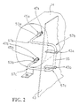
- the externally visible duct 15 is thermally preformed so as to form a predetermined number of bendings, in the exemplary embodiment four bendings 57a, 57b, 57c and 57d (Figs. 1, 2). Those bendings are arranged to locate portion 55, visible by the operator and preferably rectilinear, in correspondence of window 21, and to locate two fastening ends 53a and 53b, respectively, in correspondence of boiler 14, to which said ends can be directly fastened.
- the duct is made of FEP (modified copolymer of tetraFluoroEthylene and hexafluoroPropylene) or Teflon FEP, e.g. of the type TE-9302-N produced by DuPont company, but other materials having characteristics ensuring transparency and preforming capability may be used without departing from the scope of the invention as disclosed.
- FEP modified copolymer of tetraFluoroEthylene and hexafluoroPropylene
- Teflon FEP e.g. of the type TE-9302-N produced by DuPont company, but other materials having characteristics ensuring transparency and preforming capability may be used without departing from the scope of the invention as disclosed.
- Fittings 45a and 45b are fastened in known manner to respective fastening ends (duct ends) 53a and 53b.
- Said fittings include threaded nuts which, in use, are arranged to be coupled, in known manner, with corresponding threaded boiler joints (connecting points) 47a and 47b, known per se, which are soldered or fastened to boiler 14.
- the boiler 14 is supported by a base bracket 41, e.g. fastened to the base of body 12.
- base bracket 41 has fastened thereto a supporting bracket 43 configured so as to support at least the rectilinear, externally visible duct portion 55 in position, in correspondence of the viewing window 21.
- supporting bracket 43 includes, in the preferred embodiment, a pair of plates 43a and 43b that can be removably coupled with the ends of externally visible portion 55, near bendings 57a and 57c.
- the supporting bracket 43 includes, in correspondence of the surface lying between plates 43a and 43b, a preferably white background panel, adapted to enable an easy view of portion 55 through window 21.
- bracket 41 can be missing and plates 43a and 43b, if provided, can be directly fastened or soldered to boiler 14.
- the duct 15 itself is fastened to boiler 14 by means of fittings 45a and 45b and firmly located with its portion 55 in correspondence of window 21 by coupling plates 43a and 43b with the ends of rectilinear portion 55.
- externally visible duct 15 is operative to make the level of the liquid in boiler 14 visible to the operator.
- duct 15 is equivalent to the operation of the known assemblies for coupling with the boiler and including the prior art ducts.
- duct 15 is made of a single piece, only two fittings are needed for connection to boiler 14.
- the duct as described can readily replace prior art externally visible duct assemblies including at least one duct, multiple fitting pairs and multiple coupling ducts.
- suitably shaped duct 15 is arranged to achieve, by means of a single duct, one fitting pair and multiple bendings, a complex assembly which otherwise could be achieved only in a much more complex manner.
Landscapes
- Engineering & Computer Science (AREA)
- Food Science & Technology (AREA)
- Physics & Mathematics (AREA)
- Fluid Mechanics (AREA)
- General Physics & Mathematics (AREA)
- Infusion, Injection, And Reservoir Apparatuses (AREA)
- Rigid Pipes And Flexible Pipes (AREA)
- Apparatus For Making Beverages (AREA)
Abstract
Description
- The present invention generally relates to an externally visible duct for an infusion machine, wherein the infusion machine includes at least one boiler for heating the liquid necessary for preparing infusions and the duct is coupled with the boiler so as to show the level of the liquid in the boiler.
- Specifically, the present invention relates to an externally visible duct or level pipe arranged to show the level or free surface of a liquid, e.g. water, present in the boiler of an automatic espresso coffee machine.
- Externally visible level pipes of an infusion machine are known, which enable an operator of the machine to detect the level of liquid in the boiler.
- In particular, it is known that infusion machines, particularly espresso coffee machines, comprise a boiler mounted within a body and hidden from view, where water for infusion preparation is heated. It is also known that such machines generally include a transparent duct (externally visible duct or level pipe), which, when located in a visible position and suitably coupled with the boiler so as to exploit the physical principle of communicating vessels, is arranged to make visible the level of liquid in the boiler.
- The prior art externally visible ducts are made of transparent material, e.g. glass, Teflon or other plastic material, and they preferably have a cylindrical shape. Such ducts have a first end coupled with a first connection, arranged at a top position on the boiler, through a first fitting made e.g. of brass and a first duct made e.g. of copper, and a second end coupled with a second connection, arranged at a bottom position on the boiler, through a second fitting and a second duct with equivalent characteristics to the described ones.
- According to the Applicant, the whole of the ducts and fittings forms a particularly complex assembly generating a number of problems.
- Firstly, the assembly has a plurality of connecting points and hence a plurality of points where leaks, e.g. of steam or water, can occur.
- Secondly, the assembly, having a plurality of ducts and fittings, entails particularly long assembling times.
- Lastly, since the assembly includes rigid ducts, e.g. the copper ducts for coupling with the boiler, mounting the externally visible duct and the fittings is a particularly difficult and critical operation.
- It is an object of the present invention to solve the above-mentioned problems of the
- The object is achieved by the externally visible duct for an infusion machine having the features disclosed in the appended claims.
- The present invention also relates to a boiler and an infusion machine, respectively, including the externally visible duct according to the invention.
- The claims are an integral part of the technical teaching provided here in respect of the invention.
- According to a preferred embodiment, the externally visible duct for a boiler of an infusion machine includes first and second coupling members adapted to be directly coupled with the boiler.
- According to another feature of the present invention, the externally visible duct has one or more bendings adapted to locate a duct portion in a readily visible position and to locate the duct ends near the boiler, respectively.
- According to yet another feature of the present invention, the externally visible duct is made of plastic material, e.g. Teflon FEP.
- The above and other features of the present invention will become apparent from the following description of a preferred embodiment, made for exemplifying and non-limiting purposes with reference to the accompanying drawings, in which elements denoted by a same or similar numerical reference correspond to components having the same or similar function and construction, and in which:
- Fig. 1 is an overall view of a coffee machine including the externally visible duct according to the invention; and
- Fig. 2 shows a detailed view of the externally visible duct according to the invention.
- Referring to Fig. 1, an
infusion machine 10, e.g. an espresso coffee machine, includes abody 12 enclosing aboiler 14, of known type, for heating the liquid necessary for infusion preparation, e.g., water, and an externally visible duct (level pipe or duct) 15. - Body has, in a front area A, a
viewing window 21, of known type, enabling an operator to see at least aportion 55 of externallyvisible duct 15. - In the preferred embodiment,
duct 15 is made of a single piece of transparent plastic material and, in use, the duct ends can advantageously be directly fastened toboiler 14. - More particularly, according to the preferred embodiment, the externally
visible duct 15 is thermally preformed so as to form a predetermined number of bendings, in the exemplary embodiment fourbendings portion 55, visible by the operator and preferably rectilinear, in correspondence ofwindow 21, and to locate twofastening ends boiler 14, to which said ends can be directly fastened. - Preferably, the duct is made of FEP (modified copolymer of tetraFluoroEthylene and hexafluoroPropylene) or Teflon FEP, e.g. of the type TE-9302-N produced by DuPont company, but other materials having characteristics ensuring transparency and preforming capability may be used without departing from the scope of the invention as disclosed.
-
Fittings boiler 14. - In the preferred embodiment, the
boiler 14 is supported by abase bracket 41, e.g. fastened to the base ofbody 12. - More preferably,
base bracket 41 has fastened thereto a supportingbracket 43 configured so as to support at least the rectilinear, externallyvisible duct portion 55 in position, in correspondence of theviewing window 21. - More particularly, supporting
bracket 43 includes, in the preferred embodiment, a pair ofplates visible portion 55, nearbendings - Preferably, the supporting
bracket 43 includes, in correspondence of the surface lying betweenplates portion 55 throughwindow 21. - Of course, in other embodiments,
bracket 41 can be missing andplates boiler 14. - When mounting
duct 15, in the preferred embodiment, theduct 15 itself, already preformed, is fastened toboiler 14 by means offittings portion 55 in correspondence ofwindow 21 bycoupling plates rectilinear portion 55. - After such an operation, externally
visible duct 15 is operative to make the level of the liquid inboiler 14 visible to the operator. - The operation of
duct 15, as described, is equivalent to the operation of the known assemblies for coupling with the boiler and including the prior art ducts. Advantageously however, since according to thepresent invention duct 15 is made of a single piece, only two fittings are needed for connection toboiler 14. - Still more advantageously, the duct as described can readily replace prior art externally visible duct assemblies including at least one duct, multiple fitting pairs and multiple coupling ducts. Indeed, thanks to the invention, suitably shaped
duct 15 is arranged to achieve, by means of a single duct, one fitting pair and multiple bendings, a complex assembly which otherwise could be achieved only in a much more complex manner. - Obvious changes and modifications can be made to the above description, in respect of sizes, shapes, materials, components and connections, as well as in respect of the details of the disclosed construction and the operating method, without departing from the spirit of the invention as defined in the following claims.
Claims (10)
- An externally visible duct for a boiler (14) of an infusion machine (10), which duct includes first and second coupling members (45a, 45b, 53a, 53b) and is configured so as to make the level of liquid in the boiler (14) visible, characterised in that said first and second coupling members (45a, 45b, 53a, 53b) are arranged to be directly coupled with said boiler (14) at corresponding connection points (47a, 47b) of said boiler (14).
- The externally visible duct as claimed in claim 1, characterised in that it includes:- a portion (55) arranged to show the level of the liquid in the boiler (14);- one or more bendings located between first and second ends of said portion (55) and said first and second coupling members (45a, 45b, 53a, 53b), respectively, of said duct (15).
- The externally visible duct as claimed in any one of preceding claims, characterised in that said first and second coupling members (45a, 45b, 53a, 53b) of said duct (15) respectively include:- first and second ends (53a, 53b) of said duct (15);- first and second fitting members (45a, 45b) associated with said first and second ends (53a, 53b), respectively, and arranged to be rigidly coupled with said boiler (14).
- The externally visible duct as claimed in any one of preceding claims, characterised in that first and second coupling members (45a, 45b, 53a, 53b) of said duct are threaded and are arranged to be directly coupled with said connection points (47a, 47b) of said boiler (14).
- The externally visible duct as claimed in any one of preceding claims, characterised in that it is associable, in use, with at least one plate (43a, 43b) configured to steadily maintain the positioning of the duct (15) relative to said boiler (14).
- The externally visible duct as claimed in any one of claims 1 to 4, characterised in that it is associable, in use, with a bracket (43) having at least one plate (43a, 43b) configured to steadily maintain the positioning of the duct (15) relative to said boiler (14).
- The externally visible duct as claimed in any one of preceding claims, characterised in that it is made of transparent plastic material.
- The externally visible duct as claimed in claim 7, characterised in that said plastic material is an FEP-like material.
- A boiler (14) for an infusion machine (10), characterised in that it includes an externally visible duct as claimed in any one of claims 1 to 8.
- An infusion machine (10), including:- a boiler (14) arranged to heat a liquid necessary for preparing said infusions,- an externally visible duct (15) as claimed in any one of claims 1 to 8, coupled with said boiler (14).
Applications Claiming Priority (1)
| Application Number | Priority Date | Filing Date | Title |
|---|---|---|---|
| ITTO20060068 ITTO20060068U1 (en) | 2006-05-10 | 2006-05-10 | PIPELINE FOR INFUSION MACHINE |
Publications (2)
| Publication Number | Publication Date |
|---|---|
| EP1854385A1 true EP1854385A1 (en) | 2007-11-14 |
| EP1854385B1 EP1854385B1 (en) | 2015-07-15 |
Family
ID=38515528
Family Applications (1)
| Application Number | Title | Priority Date | Filing Date |
|---|---|---|---|
| EP07107713.5A Not-in-force EP1854385B1 (en) | 2006-05-10 | 2007-05-08 | Externally visible duct for infusion machine |
Country Status (3)
| Country | Link |
|---|---|
| EP (1) | EP1854385B1 (en) |
| ES (1) | ES2547225T3 (en) |
| IT (1) | ITTO20060068U1 (en) |
Citations (3)
| Publication number | Priority date | Publication date | Assignee | Title |
|---|---|---|---|---|
| FR1234379A (en) | 1958-08-11 | 1960-10-17 | Level indicator for coffee machines | |
| US5060560A (en) * | 1990-01-09 | 1991-10-29 | Vandemark Lowell | Low-water element safety control |
| ES2060500A2 (en) | 1992-05-19 | 1994-11-16 | Pivert Sa | Novel self-cleaning fluid conduction system, with safety device, for display of the level in the boiler in espresso coffee machines |
-
2006
- 2006-05-10 IT ITTO20060068 patent/ITTO20060068U1/en unknown
-
2007
- 2007-05-08 EP EP07107713.5A patent/EP1854385B1/en not_active Not-in-force
- 2007-05-08 ES ES07107713.5T patent/ES2547225T3/en active Active
Patent Citations (3)
| Publication number | Priority date | Publication date | Assignee | Title |
|---|---|---|---|---|
| FR1234379A (en) | 1958-08-11 | 1960-10-17 | Level indicator for coffee machines | |
| US5060560A (en) * | 1990-01-09 | 1991-10-29 | Vandemark Lowell | Low-water element safety control |
| ES2060500A2 (en) | 1992-05-19 | 1994-11-16 | Pivert Sa | Novel self-cleaning fluid conduction system, with safety device, for display of the level in the boiler in espresso coffee machines |
Also Published As
| Publication number | Publication date |
|---|---|
| EP1854385B1 (en) | 2015-07-15 |
| ITTO20060068U1 (en) | 2007-11-11 |
| ES2547225T3 (en) | 2015-10-02 |
Similar Documents
| Publication | Publication Date | Title |
|---|---|---|
| US12137835B1 (en) | Automatic cooking machine having a blocking element for magnetically attaching on a moving arm | |
| CN202695826U (en) | Sealing device, cordless electrical connector and appliance having the cordless electrical connector | |
| TWI369193B (en) | Steam unit with external fastening, including a tank for frothing milk and heating beverages, for a machine for espresso beverages | |
| ES2827237T3 (en) | Cooking container for a food processor, food processor and heating element manufacturing process | |
| JP2014158948A (en) | Modular assembly of beverage preparation machine | |
| CN101820803A (en) | Boiler for heating water in coffee machines | |
| CN109416052A (en) | Lid for centrifugal pump | |
| EP1854385A1 (en) | Externally visible duct for infusion machine | |
| US7677160B2 (en) | Boiler assembly for a griddle | |
| CN206333728U (en) | Heating vessel | |
| US20130104874A1 (en) | Cook top unit for cooker | |
| JPWO2020161897A1 (en) | Water heater | |
| US742961A (en) | Cooking utensil. | |
| CN212321023U (en) | Gas tightness detection device for gas cooker production | |
| EP1968417B1 (en) | A coffeepot | |
| JP5117331B2 (en) | Heating container | |
| CN203215984U (en) | Liquid heating utensil, heater of liquid heating utensil and heat transmitting plate | |
| US12432822B2 (en) | Cooktop appliance and dual wire sensor assembly | |
| JP2007040614A (en) | Upper surface operating type stove | |
| KR20140059544A (en) | Connection structure for hot water distributer made of engineering plastic material and hot water distributer having the same | |
| CN207527853U (en) | The heating-pipe structure of electric heater | |
| CN113243756B (en) | cooking visible steam rice cooker | |
| CN213155456U (en) | Far infrared heating plate and kitchen appliance | |
| EP3903041B1 (en) | A cooking device comprising a water tank | |
| CN117547148A (en) | Heating box and coffee machine comprising same |
Legal Events
| Date | Code | Title | Description |
|---|---|---|---|
| PUAI | Public reference made under article 153(3) epc to a published international application that has entered the european phase |
Free format text: ORIGINAL CODE: 0009012 |
|
| AK | Designated contracting states |
Kind code of ref document: A1 Designated state(s): AT BE BG CH CY CZ DE DK EE ES FI FR GB GR HU IE IS IT LI LT LU LV MC MT NL PL PT RO SE SI SK TR |
|
| AX | Request for extension of the european patent |
Extension state: AL BA HR MK YU |
|
| 17P | Request for examination filed |
Effective date: 20080326 |
|
| 17Q | First examination report despatched |
Effective date: 20080507 |
|
| AKX | Designation fees paid |
Designated state(s): AT BE BG CH CY CZ DE DK EE ES FI FR GB GR HU IE IS IT LI LT LU LV MC MT NL PL PT RO SE SI SK TR |
|
| RAP1 | Party data changed (applicant data changed or rights of an application transferred) |
Owner name: RANCILIO GROUP S.P.A. |
|
| GRAP | Despatch of communication of intention to grant a patent |
Free format text: ORIGINAL CODE: EPIDOSNIGR1 |
|
| INTG | Intention to grant announced |
Effective date: 20150209 |
|
| GRAS | Grant fee paid |
Free format text: ORIGINAL CODE: EPIDOSNIGR3 |
|
| GRAA | (expected) grant |
Free format text: ORIGINAL CODE: 0009210 |
|
| AK | Designated contracting states |
Kind code of ref document: B1 Designated state(s): AT BE BG CH CY CZ DE DK EE ES FI FR GB GR HU IE IS IT LI LT LU LV MC MT NL PL PT RO SE SI SK TR |
|
| REG | Reference to a national code |
Ref country code: CH Ref legal event code: EP Ref country code: GB Ref legal event code: FG4D |
|
| REG | Reference to a national code |
Ref country code: IE Ref legal event code: FG4D |
|
| REG | Reference to a national code |
Ref country code: AT Ref legal event code: REF Ref document number: 736316 Country of ref document: AT Kind code of ref document: T Effective date: 20150815 |
|
| REG | Reference to a national code |
Ref country code: DE Ref legal event code: R096 Ref document number: 602007042136 Country of ref document: DE |
|
| REG | Reference to a national code |
Ref country code: ES Ref legal event code: FG2A Ref document number: 2547225 Country of ref document: ES Kind code of ref document: T3 Effective date: 20151002 |
|
| REG | Reference to a national code |
Ref country code: AT Ref legal event code: MK05 Ref document number: 736316 Country of ref document: AT Kind code of ref document: T Effective date: 20150715 |
|
| REG | Reference to a national code |
Ref country code: NL Ref legal event code: MP Effective date: 20150715 |
|
| REG | Reference to a national code |
Ref country code: LT Ref legal event code: MG4D |
|
| PG25 | Lapsed in a contracting state [announced via postgrant information from national office to epo] |
Ref country code: LV Free format text: LAPSE BECAUSE OF FAILURE TO SUBMIT A TRANSLATION OF THE DESCRIPTION OR TO PAY THE FEE WITHIN THE PRESCRIBED TIME-LIMIT Effective date: 20150715 Ref country code: FI Free format text: LAPSE BECAUSE OF FAILURE TO SUBMIT A TRANSLATION OF THE DESCRIPTION OR TO PAY THE FEE WITHIN THE PRESCRIBED TIME-LIMIT Effective date: 20150715 Ref country code: LT Free format text: LAPSE BECAUSE OF FAILURE TO SUBMIT A TRANSLATION OF THE DESCRIPTION OR TO PAY THE FEE WITHIN THE PRESCRIBED TIME-LIMIT Effective date: 20150715 Ref country code: GR Free format text: LAPSE BECAUSE OF FAILURE TO SUBMIT A TRANSLATION OF THE DESCRIPTION OR TO PAY THE FEE WITHIN THE PRESCRIBED TIME-LIMIT Effective date: 20151016 |
|
| PG25 | Lapsed in a contracting state [announced via postgrant information from national office to epo] |
Ref country code: AT Free format text: LAPSE BECAUSE OF FAILURE TO SUBMIT A TRANSLATION OF THE DESCRIPTION OR TO PAY THE FEE WITHIN THE PRESCRIBED TIME-LIMIT Effective date: 20150715 Ref country code: PL Free format text: LAPSE BECAUSE OF FAILURE TO SUBMIT A TRANSLATION OF THE DESCRIPTION OR TO PAY THE FEE WITHIN THE PRESCRIBED TIME-LIMIT Effective date: 20150715 Ref country code: SE Free format text: LAPSE BECAUSE OF FAILURE TO SUBMIT A TRANSLATION OF THE DESCRIPTION OR TO PAY THE FEE WITHIN THE PRESCRIBED TIME-LIMIT Effective date: 20150715 Ref country code: PT Free format text: LAPSE BECAUSE OF FAILURE TO SUBMIT A TRANSLATION OF THE DESCRIPTION OR TO PAY THE FEE WITHIN THE PRESCRIBED TIME-LIMIT Effective date: 20151116 |
|
| REG | Reference to a national code |
Ref country code: DE Ref legal event code: R097 Ref document number: 602007042136 Country of ref document: DE |
|
| PG25 | Lapsed in a contracting state [announced via postgrant information from national office to epo] |
Ref country code: SK Free format text: LAPSE BECAUSE OF FAILURE TO SUBMIT A TRANSLATION OF THE DESCRIPTION OR TO PAY THE FEE WITHIN THE PRESCRIBED TIME-LIMIT Effective date: 20150715 Ref country code: EE Free format text: LAPSE BECAUSE OF FAILURE TO SUBMIT A TRANSLATION OF THE DESCRIPTION OR TO PAY THE FEE WITHIN THE PRESCRIBED TIME-LIMIT Effective date: 20150715 Ref country code: DK Free format text: LAPSE BECAUSE OF FAILURE TO SUBMIT A TRANSLATION OF THE DESCRIPTION OR TO PAY THE FEE WITHIN THE PRESCRIBED TIME-LIMIT Effective date: 20150715 Ref country code: CZ Free format text: LAPSE BECAUSE OF FAILURE TO SUBMIT A TRANSLATION OF THE DESCRIPTION OR TO PAY THE FEE WITHIN THE PRESCRIBED TIME-LIMIT Effective date: 20150715 |
|
| PLBE | No opposition filed within time limit |
Free format text: ORIGINAL CODE: 0009261 |
|
| STAA | Information on the status of an ep patent application or granted ep patent |
Free format text: STATUS: NO OPPOSITION FILED WITHIN TIME LIMIT |
|
| PG25 | Lapsed in a contracting state [announced via postgrant information from national office to epo] |
Ref country code: RO Free format text: LAPSE BECAUSE OF FAILURE TO SUBMIT A TRANSLATION OF THE DESCRIPTION OR TO PAY THE FEE WITHIN THE PRESCRIBED TIME-LIMIT Effective date: 20150715 |
|
| 26N | No opposition filed |
Effective date: 20160418 |
|
| PG25 | Lapsed in a contracting state [announced via postgrant information from national office to epo] |
Ref country code: IS Free format text: LAPSE BECAUSE OF FAILURE TO SUBMIT A TRANSLATION OF THE DESCRIPTION OR TO PAY THE FEE WITHIN THE PRESCRIBED TIME-LIMIT Effective date: 20150715 |
|
| PG25 | Lapsed in a contracting state [announced via postgrant information from national office to epo] |
Ref country code: BE Free format text: LAPSE BECAUSE OF NON-PAYMENT OF DUE FEES Effective date: 20160531 Ref country code: SI Free format text: LAPSE BECAUSE OF FAILURE TO SUBMIT A TRANSLATION OF THE DESCRIPTION OR TO PAY THE FEE WITHIN THE PRESCRIBED TIME-LIMIT Effective date: 20150715 |
|
| REG | Reference to a national code |
Ref country code: DE Ref legal event code: R119 Ref document number: 602007042136 Country of ref document: DE |
|
| PG25 | Lapsed in a contracting state [announced via postgrant information from national office to epo] |
Ref country code: BE Free format text: LAPSE BECAUSE OF FAILURE TO SUBMIT A TRANSLATION OF THE DESCRIPTION OR TO PAY THE FEE WITHIN THE PRESCRIBED TIME-LIMIT Effective date: 20150715 Ref country code: LU Free format text: LAPSE BECAUSE OF FAILURE TO SUBMIT A TRANSLATION OF THE DESCRIPTION OR TO PAY THE FEE WITHIN THE PRESCRIBED TIME-LIMIT Effective date: 20160508 |
|
| REG | Reference to a national code |
Ref country code: CH Ref legal event code: PL |
|
| GBPC | Gb: european patent ceased through non-payment of renewal fee |
Effective date: 20160508 |
|
| PG25 | Lapsed in a contracting state [announced via postgrant information from national office to epo] |
Ref country code: LI Free format text: LAPSE BECAUSE OF NON-PAYMENT OF DUE FEES Effective date: 20160531 Ref country code: CH Free format text: LAPSE BECAUSE OF NON-PAYMENT OF DUE FEES Effective date: 20160531 |
|
| REG | Reference to a national code |
Ref country code: IE Ref legal event code: MM4A |
|
| REG | Reference to a national code |
Ref country code: FR Ref legal event code: ST Effective date: 20170131 |
|
| PG25 | Lapsed in a contracting state [announced via postgrant information from national office to epo] |
Ref country code: FR Free format text: LAPSE BECAUSE OF NON-PAYMENT OF DUE FEES Effective date: 20160531 Ref country code: DE Free format text: LAPSE BECAUSE OF NON-PAYMENT OF DUE FEES Effective date: 20161201 |
|
| PG25 | Lapsed in a contracting state [announced via postgrant information from national office to epo] |
Ref country code: IE Free format text: LAPSE BECAUSE OF NON-PAYMENT OF DUE FEES Effective date: 20160508 Ref country code: GB Free format text: LAPSE BECAUSE OF NON-PAYMENT OF DUE FEES Effective date: 20160508 |
|
| PG25 | Lapsed in a contracting state [announced via postgrant information from national office to epo] |
Ref country code: NL Free format text: LAPSE BECAUSE OF FAILURE TO SUBMIT A TRANSLATION OF THE DESCRIPTION OR TO PAY THE FEE WITHIN THE PRESCRIBED TIME-LIMIT Effective date: 20150715 |
|
| PG25 | Lapsed in a contracting state [announced via postgrant information from national office to epo] |
Ref country code: CY Free format text: LAPSE BECAUSE OF FAILURE TO SUBMIT A TRANSLATION OF THE DESCRIPTION OR TO PAY THE FEE WITHIN THE PRESCRIBED TIME-LIMIT Effective date: 20150715 Ref country code: HU Free format text: LAPSE BECAUSE OF FAILURE TO SUBMIT A TRANSLATION OF THE DESCRIPTION OR TO PAY THE FEE WITHIN THE PRESCRIBED TIME-LIMIT; INVALID AB INITIO Effective date: 20070508 |
|
| PG25 | Lapsed in a contracting state [announced via postgrant information from national office to epo] |
Ref country code: MT Free format text: LAPSE BECAUSE OF NON-PAYMENT OF DUE FEES Effective date: 20160531 Ref country code: TR Free format text: LAPSE BECAUSE OF FAILURE TO SUBMIT A TRANSLATION OF THE DESCRIPTION OR TO PAY THE FEE WITHIN THE PRESCRIBED TIME-LIMIT Effective date: 20150715 Ref country code: MC Free format text: LAPSE BECAUSE OF FAILURE TO SUBMIT A TRANSLATION OF THE DESCRIPTION OR TO PAY THE FEE WITHIN THE PRESCRIBED TIME-LIMIT Effective date: 20150715 |
|
| PG25 | Lapsed in a contracting state [announced via postgrant information from national office to epo] |
Ref country code: BG Free format text: LAPSE BECAUSE OF FAILURE TO SUBMIT A TRANSLATION OF THE DESCRIPTION OR TO PAY THE FEE WITHIN THE PRESCRIBED TIME-LIMIT Effective date: 20150715 |
|
| PGFP | Annual fee paid to national office [announced via postgrant information from national office to epo] |
Ref country code: IT Payment date: 20210517 Year of fee payment: 15 |
|
| PGFP | Annual fee paid to national office [announced via postgrant information from national office to epo] |
Ref country code: ES Payment date: 20210602 Year of fee payment: 15 |
|
| REG | Reference to a national code |
Ref country code: ES Ref legal event code: FD2A Effective date: 20230627 |
|
| PG25 | Lapsed in a contracting state [announced via postgrant information from national office to epo] |
Ref country code: IT Free format text: LAPSE BECAUSE OF NON-PAYMENT OF DUE FEES Effective date: 20220508 Ref country code: ES Free format text: LAPSE BECAUSE OF NON-PAYMENT OF DUE FEES Effective date: 20220509 |