EP1852655A2 - A method and arrangement for expanding a primary and secondary flame in a combustor - Google Patents
A method and arrangement for expanding a primary and secondary flame in a combustor Download PDFInfo
- Publication number
- EP1852655A2 EP1852655A2 EP07107419A EP07107419A EP1852655A2 EP 1852655 A2 EP1852655 A2 EP 1852655A2 EP 07107419 A EP07107419 A EP 07107419A EP 07107419 A EP07107419 A EP 07107419A EP 1852655 A2 EP1852655 A2 EP 1852655A2
- Authority
- EP
- European Patent Office
- Prior art keywords
- centerbody
- fluid flow
- combustor
- downstream end
- upstream
- Prior art date
- Legal status (The legal status is an assumption and is not a legal conclusion. Google has not performed a legal analysis and makes no representation as to the accuracy of the status listed.)
- Withdrawn
Links
Images



Classifications
-
- F—MECHANICAL ENGINEERING; LIGHTING; HEATING; WEAPONS; BLASTING
- F23—COMBUSTION APPARATUS; COMBUSTION PROCESSES
- F23R—GENERATING COMBUSTION PRODUCTS OF HIGH PRESSURE OR HIGH VELOCITY, e.g. GAS-TURBINE COMBUSTION CHAMBERS
- F23R3/00—Continuous combustion chambers using liquid or gaseous fuel
- F23R3/02—Continuous combustion chambers using liquid or gaseous fuel characterised by the air-flow or gas-flow configuration
- F23R3/16—Continuous combustion chambers using liquid or gaseous fuel characterised by the air-flow or gas-flow configuration with devices inside the flame tube or the combustion chamber to influence the air or gas flow
Definitions
- a combustor 20 (which could be used in the gas turbine 10 of Figure 1) defining a liner cavity 23 and including a venturi 22 and a centerbody 24 is illustrated.
- the centerbody 24 includes an upstream end 30 and a downstream end 32.
- the venturi 22 defines a venturi throat 28 that is disposed radially outwardly of the centerbody 24.
- the venturi throat 28 (as shown in Figure 2) is disposed downstream of the downstream end 32 of the centerbody 24, and an annular cavity 35 is disposed annularly outwardly about the centerbody 24. From this annularly cavity 35, an annular fluid flow 34 flows into and past a recirculation region 21 of the liner cavity 23. Also flowing into the liner cavity 23 is a center fluid flow 36, which flows from the centerbody 24.
Landscapes
- Engineering & Computer Science (AREA)
- Chemical & Material Sciences (AREA)
- Combustion & Propulsion (AREA)
- Mechanical Engineering (AREA)
- General Engineering & Computer Science (AREA)
Abstract
Description
- This disclosure relates generally to a combustor with improved emissions performance, and more particularly to a combustor with improved emissions performance and stability.
- Gas turbines comprise a compressor for compressing air, a combustor for producing a hot gas by burning fuel in the presence of the compressed air produced by the compressor, and a turbine to extract work from the expanding hot gas produced by the combustor. Gas turbines are known to emit undesirable oxides of nitrogen (NOx) and carbon monoxide (CO). Existing dry low NOx combustors (DLN combustors) minimize the generation of NOx, carbon monoxide, and other pollutants. These DLN combustors accommodate fuel-lean mixtures while avoiding the existence of unstable flames and the possibility of flame blowouts by allowing a portion of flame-zone air to mix with the fuel at lower loads. However, NOx emissions requirements are becoming more stringent, and therefore, the art is need of a lower NOx emission combustor that will not reduce combustor stability or increase CO emissions.
- Disclosed is an arrangement for expanding an annular fluid flow and a center fluid flow, comprising a combustor including a venturi and a centerbody, the centerbody including an upstream end and a downstream end, and a venturi throat defined by the venturi and disposed upstream of .19 inches downstream of the downstream end of the centerbody.
- Also disclosed is a method for arranging components to produce an expansion of an annular fluid flow and a center fluid flow in a combustor, comprising disposing a venturi throat radially outwardly of a centerbody of the combustor, and disposing the venturi throat upstream of .19 inches downstream of a downstream end of the centerbody.
- Additionally disclosed is a method for reducing NOx emissions by enhancing flame stability and reducing CO emissions in a combustor, comprising directing an annular fluid flow toward a centerbody of the combustor, the directing occurring upstream of .19 inches downstream of a downstream end of the centerbody, expanding the annular fluid flow away from the centerbody, the expanding occurring upstream of .19 inches downstream of the downstream end of the centerbody, drawing a center fluid flow radially outwardly via the expanding, and increasing a centerline recirculation region size.
- The foregoing and other features and advantages of the present invention should be more fully understood from the following detailed description of illustrative embodiments, provided by way of example only, taken in conjunction with the accompanying Figures in which like elements are numbered alike in the several Figures:
- Figure 1 is a schematic of a gas turbine;
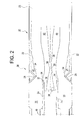
- Figure 2 is a schematic cross section view of a combustor;
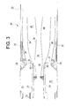
- Figure 3 is a schematic cross section view of a combustor including components in an arrangement that improves expansion of an annular fluid flow and a center fluid flow in accordance with an exemplary embodiment;
- Figure 4 is a block diagram illustrating a method for arranging components to produce an expansion of an annular fluid flow and center fluid flow in a combustor; and
- Figure 5 is a block diagram illustrating a method for reducing NOx emissions while enhancing flame stability in a combustor.
- For clarity and perspective, an example of a combustor in association with a gas turbine is shown in Figure 1. It is to be understood that the disclosed arrangement (an arrangement for expanding an annular fluid flow and a center fluid flow) has applicability beyond the turbine shown in Figure 1, and thus, the turbine in Figure 1 should not be considered limiting to the disclosure.
- As shown in Figure 1, a
gas turbine 10 includes acombustor 12 located in a gas flow path between acompressor 14 and aturbine 16. Theturbine 16 is coupled to thecompressor 14, which it rotationally drives, and a poweroutput drive shaft 18. Air enters thegas turbine 10 and passes through thecompressor 14. High pressure air from thecompressor 14 enters thecombustor 12 where it is mixed with fuel and burned. High energy combustion gases exit thecombustor 12 and expand in theturbine 16, whereby energy is extracted. In addition, theturbine 16 drives theoutput power shaft 18. - Referring to Figure 2, a combustor 20 (which could be used in the
gas turbine 10 of Figure 1) defining aliner cavity 23 and including aventuri 22 and acenterbody 24 is illustrated. Thecenterbody 24 includes anupstream end 30 and adownstream end 32. Theventuri 22 defines aventuri throat 28 that is disposed radially outwardly of thecenterbody 24. The venturi throat 28 (as shown in Figure 2) is disposed downstream of thedownstream end 32 of thecenterbody 24, and anannular cavity 35 is disposed annularly outwardly about thecenterbody 24. From this annularlycavity 35, anannular fluid flow 34 flows into and past arecirculation region 21 of theliner cavity 23. Also flowing into theliner cavity 23 is acenter fluid flow 36, which flows from thecenterbody 24. - Because the
venturi throat 28 is disposed downstream of thedownstream end 32, theannular fluid flow 34 is directed by theventuri throat 28 toward thecenter fluid flow 36, after theannular fluid flow 36 has exited theannular cavity 35. In this type ofarrangement 26, theannular fluid flow 34 impinges upon thecenter fluid flow 36 downstream of thedownstream end 32, creating apinching 38 of thecenter flow 36 in acenterline recirculation region 39 of theliner cavity 23. The pinching effect tends to destabilize combustor flames thereby making combustion dynamics or blow-out a greater probability. In addition (when theventuri throat 28 and thedownstream end 32 are arranged in this manner), it is not until after theannular fluid flow 36 has passed both thedownstream end 32 of thecenterbody 24 and theventuri throat 28 that it may expand and create alower pressure region 40 that will facilitate expansion of thecenter fluid flow 36. This delays interaction of a flame (not illustrated) associated with thecenter fluid flow 36 and a flame (not illustrated) associated with theannular fluid flow 34. - Referring to Figure 3, the
venturi throat 28 anddownstream end 32 of thecenterbody 24 are illustrated in an exemplary embodiment of an arrangement 42 that improves expansion of theannular fluid flow 34 andcenter fluid flow 36 in therecirculation region 21, thereby simultaneously improving both NOx reduction and flame stability. In this arrangement 42, theventuri throat 28 is disposed less than .19 inches downstream of thedownstream end 32 of thecenterbody 24. Theventuri throat 28 may be disposed less than .19 inches downstream of thedownstream end 32 of thecenterbody 24 by moving or extending thecenterbody 24 downstream, or moving theventuri throat 28 upstream within theventuri 22. In an exemplary embodiment, such as that which is shown in Figure 3, theventuri throat 28 is disposed .5 inches upstream of thedownstream end 32 of thecenterbody 24. In another exemplary embodiment, theventuri throat 28 is disposed .31 inches upstream of thedownstream end 32 of thecenterbody 24. Theventuri throat 28 may also be disposed coplanar to (or in asame plane 43 with) thedownstream end 32 of saidcenterbody 24. - By disposing the
venturi throat 28 upstream of thedownstream end 32 of thecenterbody 24 in these exemplary embodiments, theannular fluid flow 34 is directed by theventuri throat 28 toward thecenterbody 24, with the directing occurring upstream of thedownstream end 32 of thecenterbody 24. By positioning theventuri throat 28 in this manner, theannular fluid flow 34 will begin to expand before moving downstream of thedownstream end 32 of thecenterbody 24. Since theannular fluid flow 34 is already expanding as it passes thedownstream end 32 of thecenterbody 24, it does not restrict the expansion of thecenter fluid flow 36 but creates alower pressure region 46 to which thecenter fluid flow 36 will be exposed upon entry to theliner cavity 23. Thislower pressure region 46 facilitates expansion of thecenter fluid flow 36 with theannular fluid flow 34. - Earlier expansion of the center fluid flow 36 (in terms of fluid flow direction, and as compared with a component arrangement of Figure 2) enhances
center fluid flow 36 recirculation in therecirculation region 21, which allows a faster interaction between the flame (not illustrated) associated with thecenter fluid flow 36 and the flame (not illustrated) associated with theannular fluid flow 34. This faster interaction reduces cold streaks in thecombustor 20, and improves NOx emissions performance by decreasing CO emissions at a given NOx level, thereby facilitating thecombustor 20 to run at a leaner fuel-air mixture and thus produce less NOx emissions. Earlier expansion also eliminatespinching 38, which increasescenterline circulation region 39 size, and improvescombustor 20 stability. It should be appreciated that in an exemplary embodiment, thecombustor 20 is a dry low NOx combustor, which utilizes fuel-lean mixtures and does not use diluents (e.g., water injection) to reduce flame temperature. - Referring to Figure 4, a
method 100 for arranging components to produce an expansion of anannular fluid flow 34 andcenter fluid flow 36 in acombustor 20 is illustrated and includes disposing aventuri throat 28 radially outwardly of acenterbody 24 of thecombustor 20, as shown inOperational Block 102. Themethod 100 also includes disposing theventuri throat 28 upstream of .19 inches downstream of adownstream end 32 of thecenterbody 24, as shown inOperational Block 104. As was mentioned above, upstream disposal of theventuri throat 28 may be achieved by either moving thecenterbody 24 downstream or moving theventuri throat 28 upstream. It should be appreciated that in an exemplary embodiment, theventuri throat 28 is disposed upstream or coplanar with thedownstream end 32 of saidcenterbody 24. - Referring to Figure 5, a
method 200 for reducing NOx emissions by enhancing flame stability and reducing CO emissions in acombustor 20 is illustrated and includes directing anannular fluid flow 34 toward acenterbody 24 of thecombustor 20, with the directing occurring upstream of .19 inches downstream of adownstream end 32 of thecenterbody 24, as shown inOperational Block 202. Themethod 200 also includes expanding theannular fluid flow 34 away from thecenterbody 24, with the expanding occurring upstream of .19 inches downstream of thedownstream end 32 of saidcenterbody 24, as shown inOperational Block 204, and drawing acenter fluid flow 36 radially outwardly via the expanding and increasing a centerline recirculation region size, as shown inOperational Block 206. It should be appreciated that in an exemplary embodiment the directing and expanding occurs upstream or coplanar with thedownstream end 32 of saidcenterbody 24. - While the invention has been described with reference to an exemplary embodiment, it should be understood by those skilled in the art that various changes may be made and equivalents may be substituted for elements thereof without departing from the scope of the invention. In addition, many modifications may be made to adapt a particular situation or substance to the teachings of the invention without departing from the scope thereof. Therefore, it is important that the invention not be limited to the particular embodiment disclosed as the best mode contemplated for carrying out this invention, but that the invention will include all embodiments falling within the scope of the apportioned claims. Moreover, unless specifically stated any use of the terms first, second, etc. do not denote any order or importance, but rather the terms first, second, etc. are used to distinguish one element from another.
Claims (10)
- An arrangement (42) for expanding an annular fluid flow (36)and a center fluid flow (36), the arrangement (42) comprising:a combustor (12) including a venturi (22) and a centerbody (24), said centerbody (24) including an upstream end (30) and a downstream end (32); anda venturi throat (28) defined by said venturi (22) and disposed upstream of .19 inches downstream of said downstream end (32) of said centerbody (24).
- An arrangement (42) according to claim 1, wherein said venturi throat (28) is disposed at least one of upstream and coplanar to said downstream end (32) of said centerbody (24).
- An arrangement (42) according to claim 1, wherein said venturi (22) is disposed from less than .19 inches downstream of said downstream end (32) of said centerbody (24) to about .5 inches upstream of said downstream end (32) of said centerbody (24).
- An arrangement (42) according to claim 3, wherein said venturi throat (28) is disposed from about .31 inches to about .5 inches upstream of said downstream end (32) of said centerbody (24).
- An arrangement (42) according to claim 1, wherein said combustor (20) is a dry low NOx combustor (12).
- An arrangement (42) for expanding an annular fluid flow (34) and a center fluid flow(36), the arrangement (42) comprising:a combustor (12) disposed in a gas flow path between a compressor (14) and a turbine (16) within a gas turbine (10), said combustor (12) including a venturi (22) and a centerbody (24), said centerbody (24) including an upstream end (30) and a downstream end (32); anda venturi throat (28) defined by said venturi and disposed upstream of .19 inches downstream of said downstream end (32) of said centerbody. (24)
- A method (100) for arranging components to produce an expansion of an annular fluid flow (34) and a center fluid flow (36) in a combustor (12), the method (100) comprising:disposing a venturi throat (28) radially outwardly of a centerbody (24) of the combustor (12); anddisposing said venturi throat (28) upstream of .19 inches downstream of a downstream end (32) of said centerbody (24).
- A method (100) according to claim 7, wherein said disposing includes said venturi throat (28) being disposed at least one of upstream and coplanar to said downstream end (32) of said centerbody (24).
- An method (100) according to claim 7, wherein said disposing includes said venturi (22) being disposed from less than .19 inches downstream of said downstream end (32) of said centerbody to about .5 inches upstream of said downstream end (32) of said centerbody (24).
- An method (200) according to claim 9, wherein said disposing includes said venturi throat (28) being disposed from about .31 inches to about .5 inches upstream of said downstream end (32) of said centerbody (24).
Applications Claiming Priority (1)
| Application Number | Priority Date | Filing Date | Title |
|---|---|---|---|
| US11/418,239 US8156743B2 (en) | 2006-05-04 | 2006-05-04 | Method and arrangement for expanding a primary and secondary flame in a combustor |
Publications (2)
| Publication Number | Publication Date |
|---|---|
| EP1852655A2 true EP1852655A2 (en) | 2007-11-07 |
| EP1852655A3 EP1852655A3 (en) | 2014-10-01 |
Family
ID=38267694
Family Applications (1)
| Application Number | Title | Priority Date | Filing Date |
|---|---|---|---|
| EP07107419.9A Withdrawn EP1852655A3 (en) | 2006-05-04 | 2007-05-03 | A method and arrangement for expanding a primary and secondary flame in a combustor |
Country Status (4)
| Country | Link |
|---|---|
| US (1) | US8156743B2 (en) |
| EP (1) | EP1852655A3 (en) |
| JP (1) | JP2007298269A (en) |
| CN (1) | CN101067497A (en) |
Cited By (2)
| Publication number | Priority date | Publication date | Assignee | Title |
|---|---|---|---|---|
| CN102009755A (en) * | 2010-09-17 | 2011-04-13 | 燕京啤酒(桂林漓泉)股份有限公司 | Gas heat film machine |
| US8056343B2 (en) | 2008-10-01 | 2011-11-15 | General Electric Company | Off center combustor liner |
Families Citing this family (5)
| Publication number | Priority date | Publication date | Assignee | Title |
|---|---|---|---|---|
| US8020385B2 (en) * | 2008-07-28 | 2011-09-20 | General Electric Company | Centerbody cap for a turbomachine combustor and method |
| US8028529B2 (en) * | 2006-05-04 | 2011-10-04 | General Electric Company | Low emissions gas turbine combustor |
| US20110041507A1 (en) * | 2009-08-18 | 2011-02-24 | William Kirk Hessler | Integral Liner and Venturi for Eliminating Air Leakage |
| AU2016254323B2 (en) | 2015-04-30 | 2019-11-28 | Nuovo Pignone Tecnologie Srl | Ultra-low NOx emission gas turbine engine in mechanical drive applications |
| CN105240872B (en) * | 2015-09-17 | 2018-05-25 | 中国航空工业集团公司沈阳发动机设计研究所 | A kind of chamber head parts |
Family Cites Families (22)
| Publication number | Priority date | Publication date | Assignee | Title |
|---|---|---|---|---|
| US3143401A (en) * | 1961-08-17 | 1964-08-04 | Gen Electric | Supersonic fuel injector |
| GB1307634A (en) * | 1970-07-23 | 1973-02-21 | Secr Defence | Fuel injection device for a gas turbine engine |
| DE3176219D1 (en) * | 1980-12-27 | 1987-07-02 | Hitachi Ltd | Method and apparatus for controlling combustion of gasified fuel |
| DE3766807D1 (en) * | 1986-11-25 | 1991-01-31 | Gen Electric | COMBINED DIFFUSION AND PRE-MIXING PILOT BURNER. |
| US5285631A (en) * | 1990-02-05 | 1994-02-15 | General Electric Company | Low NOx emission in gas turbine system |
| US5117636A (en) * | 1990-02-05 | 1992-06-02 | General Electric Company | Low nox emission in gas turbine system |
| US5284438A (en) * | 1992-01-07 | 1994-02-08 | Koch Engineering Company, Inc. | Multiple purpose burner process and apparatus |
| US5487275A (en) * | 1992-12-11 | 1996-01-30 | General Electric Co. | Tertiary fuel injection system for use in a dry low NOx combustion system |
| IT1273369B (en) * | 1994-03-04 | 1997-07-08 | Nuovo Pignone Spa | IMPROVED LOW EMISSION COMBUSTION SYSTEM FOR GAS TURBINES |
| DE19520291A1 (en) * | 1995-06-02 | 1996-12-05 | Abb Management Ag | Combustion chamber |
| US6427446B1 (en) * | 2000-09-19 | 2002-08-06 | Power Systems Mfg., Llc | Low NOx emission combustion liner with circumferentially angled film cooling holes |
| US6591603B2 (en) * | 2001-03-08 | 2003-07-15 | Trw Inc. | Pintle injector rocket with expansion-deflection nozzle |
| US6467272B1 (en) * | 2001-06-25 | 2002-10-22 | Power Systems Mfg, Llc | Means for wear reduction in a gas turbine combustor |
| ITMI20012785A1 (en) * | 2001-12-21 | 2003-06-21 | Nuovo Pignone Spa | IMPIANT PIPE OR "LINER" IMPROVED FOR A COMBUSTION CHAMBER OF A LOW-EMISSION GAS TURBINE |
| US6735949B1 (en) * | 2002-06-11 | 2004-05-18 | General Electric Company | Gas turbine engine combustor can with trapped vortex cavity |
| US6832482B2 (en) * | 2002-06-25 | 2004-12-21 | Power Systems Mfg, Llc | Pressure ram device on a gas turbine combustor |
| US6865892B2 (en) * | 2002-12-17 | 2005-03-15 | Power Systems Mfg, Llc | Combustion chamber/venturi configuration and assembly method |
| US7082770B2 (en) * | 2003-12-24 | 2006-08-01 | Martling Vincent C | Flow sleeve for a low NOx combustor |
| US6951109B2 (en) * | 2004-01-06 | 2005-10-04 | General Electric Company | Apparatus and methods for minimizing and/or eliminating dilution air leakage in a combustion liner assembly |
| US7000403B2 (en) * | 2004-03-12 | 2006-02-21 | Power Systems Mfg., Llc | Primary fuel nozzle having dual fuel capability |
| US7389643B2 (en) * | 2005-01-31 | 2008-06-24 | General Electric Company | Inboard radial dump venturi for combustion chamber of a gas turbine |
| US8028529B2 (en) * | 2006-05-04 | 2011-10-04 | General Electric Company | Low emissions gas turbine combustor |
-
2006
- 2006-05-04 US US11/418,239 patent/US8156743B2/en not_active Expired - Fee Related
-
2007
- 2007-04-30 CN CNA2007101024516A patent/CN101067497A/en active Pending
- 2007-05-01 JP JP2007120450A patent/JP2007298269A/en not_active Withdrawn
- 2007-05-03 EP EP07107419.9A patent/EP1852655A3/en not_active Withdrawn
Cited By (2)
| Publication number | Priority date | Publication date | Assignee | Title |
|---|---|---|---|---|
| US8056343B2 (en) | 2008-10-01 | 2011-11-15 | General Electric Company | Off center combustor liner |
| CN102009755A (en) * | 2010-09-17 | 2011-04-13 | 燕京啤酒(桂林漓泉)股份有限公司 | Gas heat film machine |
Also Published As
| Publication number | Publication date |
|---|---|
| JP2007298269A (en) | 2007-11-15 |
| EP1852655A3 (en) | 2014-10-01 |
| CN101067497A (en) | 2007-11-07 |
| US8156743B2 (en) | 2012-04-17 |
| US20070256423A1 (en) | 2007-11-08 |
Similar Documents
| Publication | Publication Date | Title |
|---|---|---|
| US9310078B2 (en) | Fuel injection assemblies in combustion turbine engines | |
| US6868676B1 (en) | Turbine containing system and an injector therefor | |
| US11268438B2 (en) | Combustor liner dilution opening | |
| RU2531110C2 (en) | Gas-turbine unit and unit with injector vanes (versions) | |
| US7685823B2 (en) | Airflow distribution to a low emissions combustor | |
| US8020385B2 (en) | Centerbody cap for a turbomachine combustor and method | |
| EP1852655A2 (en) | A method and arrangement for expanding a primary and secondary flame in a combustor | |
| US20090019854A1 (en) | APPARATUS/METHOD FOR COOLING COMBUSTION CHAMBER/VENTURI IN A LOW NOx COMBUSTOR | |
| EP2889542B1 (en) | Method for operating a combustor for a gas turbine and combustor for a gas turbine | |
| KR101774630B1 (en) | Tangential annular combustor with premixed fuel and air for use on gas turbine engines | |
| KR101774094B1 (en) | Can-annular combustor with premixed tangential fuel-air nozzles for use on gas turbine engines | |
| US20030024234A1 (en) | Secondary combustor for low NOx gas combustion turbine | |
| US7308793B2 (en) | Apparatus and method for reducing carbon monoxide emissions | |
| US12560324B2 (en) | Combustion section with a primary combustor and a set of secondary combustors | |
| US20250251133A1 (en) | Turbine engine having a combustion section with a fuel supply assembly | |
| US12173898B1 (en) | Combustion section with a primary combustor and a set of secondary combustors | |
| KR20170020248A (en) | Sequential combustion arrangement with cooling gas for dilution | |
| KR101832026B1 (en) | Tangential and flameless annular combustor for use on gas turbine engines | |
| US20230194088A1 (en) | Combustor with dilution openings | |
| JP2004011947A (en) | Swirling type low NOx combustor | |
| US20100307160A1 (en) | Convex Pilot Cone | |
| EP4530532A1 (en) | Combustion section with a primary combustor and a set of secondary combustors | |
| US20250020324A1 (en) | Combustor with dilution openings | |
| US20240418369A1 (en) | Combustion section with a primary combustor and a set of secondary combustors |
Legal Events
| Date | Code | Title | Description |
|---|---|---|---|
| PUAI | Public reference made under article 153(3) epc to a published international application that has entered the european phase |
Free format text: ORIGINAL CODE: 0009012 |
|
| AK | Designated contracting states |
Kind code of ref document: A2 Designated state(s): AT BE BG CH CY CZ DE DK EE ES FI FR GB GR HU IE IS IT LI LT LU LV MC MT NL PL PT RO SE SI SK TR |
|
| AX | Request for extension of the european patent |
Extension state: AL BA HR MK YU |
|
| RIN1 | Information on inventor provided before grant (corrected) |
Inventor name: VENKATARAMAN, KRISHNA KUMAR Inventor name: POPOVIC, PREDRAG Inventor name: NEGRONI, ALBERTO JOSE Inventor name: HESSLER, WILLIAM KIRK |
|
| PUAL | Search report despatched |
Free format text: ORIGINAL CODE: 0009013 |
|
| AK | Designated contracting states |
Kind code of ref document: A3 Designated state(s): AT BE BG CH CY CZ DE DK EE ES FI FR GB GR HU IE IS IT LI LT LU LV MC MT NL PL PT RO SE SI SK TR |
|
| AX | Request for extension of the european patent |
Extension state: AL BA HR MK RS |
|
| RIC1 | Information provided on ipc code assigned before grant |
Ipc: F23R 3/16 20060101AFI20140826BHEP |
|
| STAA | Information on the status of an ep patent application or granted ep patent |
Free format text: STATUS: THE APPLICATION IS DEEMED TO BE WITHDRAWN |
|
| 18D | Application deemed to be withdrawn |
Effective date: 20141202 |