EP1852627A2 - Disc brake operating mechanism - Google Patents
Disc brake operating mechanism Download PDFInfo
- Publication number
- EP1852627A2 EP1852627A2 EP07251887A EP07251887A EP1852627A2 EP 1852627 A2 EP1852627 A2 EP 1852627A2 EP 07251887 A EP07251887 A EP 07251887A EP 07251887 A EP07251887 A EP 07251887A EP 1852627 A2 EP1852627 A2 EP 1852627A2
- Authority
- EP
- European Patent Office
- Prior art keywords
- lever
- stub axle
- bush
- cylindrical portion
- brake
- Prior art date
- Legal status (The legal status is an assumption and is not a legal conclusion. Google has not performed a legal analysis and makes no representation as to the accuracy of the status listed.)
- Granted
Links
- 230000007246 mechanism Effects 0.000 title description 11
- 230000009471 action Effects 0.000 description 4
- 239000002783 friction material Substances 0.000 description 3
- 238000004806 packaging method and process Methods 0.000 description 2
- 230000008901 benefit Effects 0.000 description 1
- 230000001010 compromised effect Effects 0.000 description 1
- 230000003993 interaction Effects 0.000 description 1
- 230000014759 maintenance of location Effects 0.000 description 1
- 238000004519 manufacturing process Methods 0.000 description 1
- 238000000034 method Methods 0.000 description 1
- 230000009467 reduction Effects 0.000 description 1
- 230000004044 response Effects 0.000 description 1
Images


Classifications
-
- F—MECHANICAL ENGINEERING; LIGHTING; HEATING; WEAPONS; BLASTING
- F16—ENGINEERING ELEMENTS AND UNITS; GENERAL MEASURES FOR PRODUCING AND MAINTAINING EFFECTIVE FUNCTIONING OF MACHINES OR INSTALLATIONS; THERMAL INSULATION IN GENERAL
- F16D—COUPLINGS FOR TRANSMITTING ROTATION; CLUTCHES; BRAKES
- F16D65/00—Parts or details
- F16D65/14—Actuating mechanisms for brakes; Means for initiating operation at a predetermined position
- F16D65/16—Actuating mechanisms for brakes; Means for initiating operation at a predetermined position arranged in or on the brake
- F16D65/18—Actuating mechanisms for brakes; Means for initiating operation at a predetermined position arranged in or on the brake adapted for drawing members together, e.g. for disc brakes
-
- F—MECHANICAL ENGINEERING; LIGHTING; HEATING; WEAPONS; BLASTING
- F16—ENGINEERING ELEMENTS AND UNITS; GENERAL MEASURES FOR PRODUCING AND MAINTAINING EFFECTIVE FUNCTIONING OF MACHINES OR INSTALLATIONS; THERMAL INSULATION IN GENERAL
- F16D—COUPLINGS FOR TRANSMITTING ROTATION; CLUTCHES; BRAKES
- F16D65/00—Parts or details
- F16D65/38—Slack adjusters
- F16D65/40—Slack adjusters mechanical
- F16D65/52—Slack adjusters mechanical self-acting in one direction for adjusting excessive play
- F16D65/56—Slack adjusters mechanical self-acting in one direction for adjusting excessive play with screw-thread and nut
- F16D65/567—Slack adjusters mechanical self-acting in one direction for adjusting excessive play with screw-thread and nut for mounting on a disc brake
-
- F—MECHANICAL ENGINEERING; LIGHTING; HEATING; WEAPONS; BLASTING
- F16—ENGINEERING ELEMENTS AND UNITS; GENERAL MEASURES FOR PRODUCING AND MAINTAINING EFFECTIVE FUNCTIONING OF MACHINES OR INSTALLATIONS; THERMAL INSULATION IN GENERAL
- F16D—COUPLINGS FOR TRANSMITTING ROTATION; CLUTCHES; BRAKES
- F16D2121/00—Type of actuator operation force
- F16D2121/14—Mechanical
-
- F—MECHANICAL ENGINEERING; LIGHTING; HEATING; WEAPONS; BLASTING
- F16—ENGINEERING ELEMENTS AND UNITS; GENERAL MEASURES FOR PRODUCING AND MAINTAINING EFFECTIVE FUNCTIONING OF MACHINES OR INSTALLATIONS; THERMAL INSULATION IN GENERAL
- F16D—COUPLINGS FOR TRANSMITTING ROTATION; CLUTCHES; BRAKES
- F16D2125/00—Components of actuators
- F16D2125/18—Mechanical mechanisms
- F16D2125/20—Mechanical mechanisms converting rotation to linear movement or vice versa
- F16D2125/22—Mechanical mechanisms converting rotation to linear movement or vice versa acting transversely to the axis of rotation
- F16D2125/28—Cams; Levers with cams
Definitions
- This invention relates to a disc brake operating mechanism and particularly to such a mechanism for a disc brake of a truck.
- Braking systems of heavy trucks generally use air under pressure as the operating medium.
- large air actuators have a mechanical output which applies brake pads to the brake rotor via a lever mechanism.
- the lever mechanism includes an operating shaft pivotable about an axis to urge one or more tappets against a brake pad via a cam surface.
- the shaft has a lever arm acted upon by the air actuator, and may include another generally shorter arm to actuate a wear adjuster.
- twin tappets are provided to optimise pressure distribution on the brake pad backplate.
- a lever mechanism will comprise an operating shaft extending on a pivot axis on either side of the brake actuator lever.
- Bearings usually needle rollers, are provided on each side of the lever to resist brake application force and to permit the operating shaft to pivot freely; twin bearings obviate twisting and end loads on the shaft.
- the bearings provided on each side of the lever sit in saddle components, fitted into the brake housing. These saddle components often provide axial retention of the bearing arrangements. The addition of saddle components increases part count, complexity of assembly and cost.
- twin bearings are provided. This arrangement adds to the cost and weight of the brake, and also results in problems in packaging the components within the smaller brake envelope, because space at the inboard side of the brake rotor is limited.
- an operating lever of a disc brake caliper said lever being adapted for pivoting movement in a brake caliper to transfer actuating force from a brake actuator to a brake pad
- said lever comprising a shaft having a pivot axis, a cam surface on said shaft at one end of said lever and operable on pivoting thereof, a lever arm extending from the shaft intermediate the ends thereof and extending over said cam surface, a wear adjuster arm extending from said lever, and a stub axle on said axis at the other end of said lever, wherein said lever has a bearing surface adapted for reactive support of said cam surface on a roller element bearing of a brake caliper, and said stub axle is adapted for support in a plain bush of a brake caliper, and wherein the diameter of said stub axle is less than the radius of said bearing surface.
- Such a lever is essentially single sided and thus has a single cam surface associated with a single brake tappet; the lever is thus smaller than prior art proposals having roller element bearing support at both sides.
- the preferably cylindrical stub axle is relatively small, yet sufficient to resist a turning movement as a result of operation of the wear adjuster arm.
- the stub axle has a diameter typically in the range 20-40% of the effective diameter of said roller element bearing.
- the lever has a first side on which said cam surface and wear adjuster arm are provided, and a second side on which said bearing surface is provided, in which the first side and the second side are substantially opposite.
- the wear adjuster arm extends from said shaft substantially at right angles to the direction of extension of said lever arm.
- the free end of said lever arm is orthogonal to the axis of said lever and over the mid point of said cam surface.
- the operating lever further includes an annular bearing housing having a plain bush adapted to said stub axle.
- cam surface is at one side of said lever arm, and said stub axle is at the other side.
- a brake caliper comprising a housing having a tappet slidable therein, and a bridge adapted to straddle a brake rotor and slidable with respect to said housing in the direction of the brake rotor axis, said caliper further including a lever according to the first aspect operably situated between said tappet and bridge, wherein said stub axle and bearing surface are supported by said bridge.
- the bridge may be a one piece component, or an assembly comprising a housing and a bridge member operatively fixed thereto.
- the axial centre of said cam surface is substantially co-incident with the axis of said tappet.
- said tappet comprises a toothed adjuster wheel screw threaded thereto on the tappet axis, and directly operable by said cam surface.
- the caliper further includes a wear adjuster immediately adjacent the tappet and having a toothed wheel in engagement with said adjuster wheel, the axes of said wheels being parallel.
- the toothed wheel of the wear adjuster is constrained to rotate uni-directionally in response to motion of said wear adjuster arm.
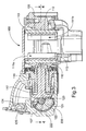
- Figs.1 and 2 illustrate schematically the operating mechanism of a single tappet brake applicator suitable for a commercial vehicle, typically a light commercial vehicle.
- An inboard brake pad 11 a comprises a backing plate 12 and a layer of friction material 13. The pad is movable in the direction of arrow 14 against a corresponding brake rotor 10. Suitable means 20 are provided to urge an outboard brake pad 11 b against the opposite side of the rotor. Such means usually comprise a bridge which spans the rotor 10 and is slidably mounted on a carrier to transmit the reaction force from the inboard operating lever.
- the inboard mechanism comprises a single brake tappet 15 slidable in the direction of arrow 14 relative to the rotor 10. Screw threaded to the tappet 15 on an axis is a toothed adjuster wheel 17. It will be appreciated that relative rotation of the wheel 17 and tappet 15 assembly in one direction causes lengthening thereof, and thus compensation for a reduction in thickness of the friction material 13 due to wear.
- a lever 21 is pivoted about a transverse axis 22 in the brake housing.
- the lever has a cam surface 23 extending across the face of the tappet 15, and an arm 24 having a pocket 25 adapted to receive an output rod (not shown) of a brake actuator.
- the arm 24 curves over the cam surface so that in plan (Fig.1) the line of action from the brake actuator (via pocket 25) is substantially over the line of action of the tappet assembly.
- the cam surface 23 may comprise a roller bearing 22a offset from the axis 22 (as depicted), or may be plain.
- Reaction force from the lever is supported directly on a bearing surface 27a acting on a row of needle rollers 27 which in turn are supported by e.g. a reaction bridge or saddle component 28, and thus by the outboard pad 11b, which is urged against the rotor 10.
- a wear adjuster 30 comprises a body 31 having a rotatable toothed wheel 32 in engagement with the adjuster wheel 17.
- An operating arm 33 (omitted from Fig.2) of the lever 21 is engageable with the wear adjuster 30 to urge rotation of the toothed wheel 32 on each arcuate movement of the lever 21 in the event that adjustment is required.
- a suitable ratchet mechanism or clutch mechanism permits movement of the wheel 32 in one direction only so that the adjuster wheel 17 is rotated as the friction material wears away, and the tappet assembly is progressively lengthened. Such ratchet adjuster mechanisms are well known and need not be further described here.
- the lever 21 has a first, or front side on which said cam surface 23 and wear adjuster operating arm 33 are provided, and a second, or rear side on which said bearing surface 27a is provided, in which the first side and the second side are substantially opposite. More specifically, the first side is proximate the inboard brake pad 11 a and the second side is distant from the inboard brake pad 11a.
- the lever 21 is arranged at one side and over the tappet assembly and needle rollers 27. Accordingly there may be some loss of stability on end loading of the lever 21 because the line of action of the actuator is offset from the line of action of the tappet assembly.
- the force exerted by the operating arm 33 of the adjuster also exerts a turning (lifting) moment on the lever 21, which is in the direction of arrow 37 (Fig.2).
- a cylindrical extension 34 also known as a stub axle
- the bearing block 35 is mounted on or forms part of e.g. the bridge 28, and is stationary relative to the tappet assembly.
- the cylindrical extension 34 is centred on the transverse axis 22 as shown in Fig.2.
- the loads resisted by the bush 36 are small, and thus the dimensions thereof can also be small.
- the diameter of the partial needle roller set may be between 2 and 5 times the diameter of the bush.
- the bush 36 supports relatively small loads generally orthogonal to the plane illustrated in Fig.1 (i.e. vertical with respect to Fig.2) whereas the needle rollers 27 bear the considerable lateral loads exerted by the lever 21.
- Axial loads may be supported in any conventional manner, for example by a thrust washer 38; the thrust washer 38 and bush 36 may be combined, and pressed into the bearing block 35 from the right, when viewing Fig. 1.
- the arrangement is considerably simplified compared with a double sided needle roller arrangement, not least because forces generated by the adjuster arm 33 are resisted independently from those of the lever arm 21. Accordingly the corresponding bearings can be sized according to the required duty, and the arrangement is not compromised by providing needle rollers on the adjuster arm side, weight is reduced, and less space is occupied.
- a further advantage is that the needle rollers need only be provided in an arc substantially as illustrated in Fig.2, i.e. with little capacity to resist loading in the vertical direction, since tappet assembly loads are generally horizontal.
- the necessary resistance to vertical loading can be provided by the bush 36 alone. This arrangement allows a further saving of space and cost.
- a single tappet brake applicator 100 suitable for a commercial vehicle, typically a light commercial vehicle is shown, and is substantially similar to the applicator hereinbefore described. Common features are the same, numbered 100 greater.
- Applicator 100 comprises an extension 134 similar to extension 34, and extension 134 comprises a first cylindrical portion 200.
- Applicator 100 further comprises a second cylindrical portion 202 as shown in Fig.6.
- the second cylindrical portion 202 has a diameter substantially greater than the first cylindrical portion 200. (Note in Fig.6 the main part of the lever arm 121 is omitted for clarity). Note that the first and the second cylindrical portions may be integral, or separate components.
- the applicator 100 therefore comprises a first extension surface 204 defined by the annular shoulder between the first cylindrical portion 200 and the second cylindrical portion 202.
- Applicator 100 further comprises a second extension surface 206 defined on a side of the second cylindrical portion 202 opposite to the first extension surface 204.
- Applicator 100 further comprises a thrust bush 208 comprising a substantially cylindrical body 210 with a blind slot 212 therethrough.
- the blind slot 212 is defined by a first thrust bush surface 216 and a second thrust bush surface 218.
- the thrust bush 208 further comprises an entry orifice 214.
- the thrust bush is configured to be mounted into the brake caliper as shown in Fig. 5.
- the cylindrical portions 200, 202 sit in the thrust bush 208 as shown in Figs. 3 to 5.
- the first extension surface 204 abuts the first thrust bush surface 216 and the second extension surface abuts the second thrust bush surface 218.
- the interaction of these surfaces therefore provides a restraint on the lever 121 in both directions of the axis 122.
- the first cylindrical portion 200 bears against the curved end of entry orifice 214 and reacts the relatively small loads generally orthogonal to the plane illustrated in Fig.4 (i.e. vertical with respect to Fig.3) in a manner similar to cylindrical extension 34.
- the caliper body 220 of applicator 100 comprises a semicircular section recess 222 to receive roller bearing 127.
- this recess is provided with a separate saddle component bolted o otherwise fixed to the caliper housing 220.
- Features of the saddle act to axially restrain the lever 121 in the directions of axis 122.
- axial restraint is not required and the saddle component may be disposed with.
- a plate 224 can be fixed to the end of the lever 121 as shown in Fig. 7. This plate in conjunction with a shoulder 226 of the lever 121 prevents the roller moving axially relative to the lever 121.
Abstract
Description
- This invention relates to a disc brake operating mechanism and particularly to such a mechanism for a disc brake of a truck.
- Braking systems of heavy trucks generally use air under pressure as the operating medium. Typically large air actuators have a mechanical output which applies brake pads to the brake rotor via a lever mechanism. The lever mechanism includes an operating shaft pivotable about an axis to urge one or more tappets against a brake pad via a cam surface. The shaft has a lever arm acted upon by the air actuator, and may include another generally shorter arm to actuate a wear adjuster. For larger brake pads, twin tappets are provided to optimise pressure distribution on the brake pad backplate.
- Typically a lever mechanism will comprise an operating shaft extending on a pivot axis on either side of the brake actuator lever. Bearings, usually needle rollers, are provided on each side of the lever to resist brake application force and to permit the operating shaft to pivot freely; twin bearings obviate twisting and end loads on the shaft. Typically, the bearings provided on each side of the lever sit in saddle components, fitted into the brake housing. These saddle components often provide axial retention of the bearing arrangements. The addition of saddle components increases part count, complexity of assembly and cost.
- For smaller brake pads a single tappet is sufficient, but nevertheless twin bearings are provided. This arrangement adds to the cost and weight of the brake, and also results in problems in packaging the components within the smaller brake envelope, because space at the inboard side of the brake rotor is limited.
- What is required is a solution to these problems which permits easier packaging, yet allows both weight and cost to be reduced.
- According to a first aspect of the invention there is provided an operating lever of a disc brake caliper, said lever being adapted for pivoting movement in a brake caliper to transfer actuating force from a brake actuator to a brake pad, said lever comprising a shaft having a pivot axis, a cam surface on said shaft at one end of said lever and operable on pivoting thereof, a lever arm extending from the shaft intermediate the ends thereof and extending over said cam surface, a wear adjuster arm extending from said lever, and a stub axle on said axis at the other end of said lever, wherein said lever has a bearing surface adapted for reactive support of said cam surface on a roller element bearing of a brake caliper, and said stub axle is adapted for support in a plain bush of a brake caliper, and wherein the diameter of said stub axle is less than the radius of said bearing surface.
- Such a lever is essentially single sided and thus has a single cam surface associated with a single brake tappet; the lever is thus smaller than prior art proposals having roller element bearing support at both sides. The preferably cylindrical stub axle is relatively small, yet sufficient to resist a turning movement as a result of operation of the wear adjuster arm. The stub axle has a diameter typically in the range 20-40% of the effective diameter of said roller element bearing.
- Preferably, the lever has a first side on which said cam surface and wear adjuster arm are provided, and a second side on which said bearing surface is provided, in which the first side and the second side are substantially opposite.
- In the preferred embodiment, the wear adjuster arm extends from said shaft substantially at right angles to the direction of extension of said lever arm. Preferably the free end of said lever arm is orthogonal to the axis of said lever and over the mid point of said cam surface.
- Preferably the operating lever further includes an annular bearing housing having a plain bush adapted to said stub axle.
- In a preferred embodiment the cam surface is at one side of said lever arm, and said stub axle is at the other side.
- According to a second aspect of the invention there is provided a brake caliper comprising a housing having a tappet slidable therein, and a bridge adapted to straddle a brake rotor and slidable with respect to said housing in the direction of the brake rotor axis, said caliper further including a lever according to the first aspect operably situated between said tappet and bridge, wherein said stub axle and bearing surface are supported by said bridge.
- The bridge may be a one piece component, or an assembly comprising a housing and a bridge member operatively fixed thereto.
- In the preferred embodiment, the axial centre of said cam surface is substantially co-incident with the axis of said tappet. Preferably said tappet comprises a toothed adjuster wheel screw threaded thereto on the tappet axis, and directly operable by said cam surface. In the preferred embodiment the caliper further includes a wear adjuster immediately adjacent the tappet and having a toothed wheel in engagement with said adjuster wheel, the axes of said wheels being parallel. Preferably the toothed wheel of the wear adjuster is constrained to rotate uni-directionally in response to motion of said wear adjuster arm.
- Other features of the invention will be apparent from the following description of a preferred embodiment of the invention in which:
- Fig.1 is a schematic plan view of a first embodiment of a single tappet brake applicator according to the invention;
- Fig.2 is a cross-sectional view on line 2-2 of Fig.1;
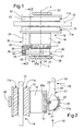
- Fig. 3 is a cross-sectional view of a second embodiment of a single tappet brake applicator according to the invention;
- Fig. 4 is a cross-sectional view on line 4-4 of Fig.3.
- Fig. 5 is a detailed view of a part of the single tappet brake applicator of Fig. 4;
- Fig. 6 is a detailed view of the thrust bush of Fig. 3;
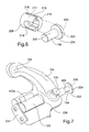
- Fig. 7 is a perspective view of the lever of Fig.3.
- Figs.1 and 2 illustrate schematically the operating mechanism of a single tappet brake applicator suitable for a commercial vehicle, typically a light commercial vehicle.
- An
inboard brake pad 11 a comprises abacking plate 12 and a layer offriction material 13. The pad is movable in the direction ofarrow 14 against acorresponding brake rotor 10.Suitable means 20 are provided to urge anoutboard brake pad 11 b against the opposite side of the rotor. Such means usually comprise a bridge which spans therotor 10 and is slidably mounted on a carrier to transmit the reaction force from the inboard operating lever. - The inboard mechanism comprises a single brake tappet 15 slidable in the direction of
arrow 14 relative to therotor 10. Screw threaded to thetappet 15 on an axis is atoothed adjuster wheel 17. It will be appreciated that relative rotation of thewheel 17 and tappet 15 assembly in one direction causes lengthening thereof, and thus compensation for a reduction in thickness of thefriction material 13 due to wear. - In order to urge the tappet assembly in the direction of
arrow 14, alever 21 is pivoted about atransverse axis 22 in the brake housing. The lever has acam surface 23 extending across the face of thetappet 15, and anarm 24 having apocket 25 adapted to receive an output rod (not shown) of a brake actuator. Thearm 24 curves over the cam surface so that in plan (Fig.1) the line of action from the brake actuator (via pocket 25) is substantially over the line of action of the tappet assembly. - The
cam surface 23 may comprise a roller bearing 22a offset from the axis 22 (as depicted), or may be plain. - Application of force in the direction of arrow 26 (Fig.2) causes arcuate movement of the
lever 21, and thus thecam surface 23 bears on the tappet assembly to urge thebrake pad 11 a directly against thebrake rotor 10. - Reaction force from the lever is supported directly on a bearing
surface 27a acting on a row ofneedle rollers 27 which in turn are supported by e.g. a reaction bridge orsaddle component 28, and thus by theoutboard pad 11b, which is urged against therotor 10. - A
wear adjuster 30 comprises abody 31 having arotatable toothed wheel 32 in engagement with theadjuster wheel 17. - An operating arm 33 (omitted from Fig.2) of the
lever 21 is engageable with thewear adjuster 30 to urge rotation of thetoothed wheel 32 on each arcuate movement of thelever 21 in the event that adjustment is required. A suitable ratchet mechanism or clutch mechanism permits movement of thewheel 32 in one direction only so that theadjuster wheel 17 is rotated as the friction material wears away, and the tappet assembly is progressively lengthened. Such ratchet adjuster mechanisms are well known and need not be further described here. - As shown in Fig. 1, the
lever 21 has a first, or front side on which saidcam surface 23 and wearadjuster operating arm 33 are provided, and a second, or rear side on which said bearingsurface 27a is provided, in which the first side and the second side are substantially opposite. More specifically, the first side is proximate theinboard brake pad 11 a and the second side is distant from theinboard brake pad 11a. - The
lever 21 is arranged at one side and over the tappet assembly andneedle rollers 27. Accordingly there may be some loss of stability on end loading of thelever 21 because the line of action of the actuator is offset from the line of action of the tappet assembly. - Furthermore, the force exerted by the
operating arm 33 of the adjuster also exerts a turning (lifting) moment on thelever 21, which is in the direction of arrow 37 (Fig.2). - To counter this turning moment and stabilise the
lever 21, a cylindrical extension 34 (also known as a stub axle) of the lever projects on theaxis 22 and is supported in abearing block 35 by aplain bush 36. Thebearing block 35 is mounted on or forms part of e.g. thebridge 28, and is stationary relative to the tappet assembly. - The
cylindrical extension 34 is centred on thetransverse axis 22 as shown in Fig.2. - The loads resisted by the
bush 36 are small, and thus the dimensions thereof can also be small. For example the diameter of the partial needle roller set may be between 2 and 5 times the diameter of the bush. - Thus the
bush 36 supports relatively small loads generally orthogonal to the plane illustrated in Fig.1 (i.e. vertical with respect to Fig.2) whereas theneedle rollers 27 bear the considerable lateral loads exerted by thelever 21. - Axial loads may be supported in any conventional manner, for example by a
thrust washer 38; thethrust washer 38 andbush 36 may be combined, and pressed into the bearingblock 35 from the right, when viewing Fig. 1. - The arrangement is considerably simplified compared with a double sided needle roller arrangement, not least because forces generated by the
adjuster arm 33 are resisted independently from those of thelever arm 21. Accordingly the corresponding bearings can be sized according to the required duty, and the arrangement is not compromised by providing needle rollers on the adjuster arm side, weight is reduced, and less space is occupied. - A further advantage is that the needle rollers need only be provided in an arc substantially as illustrated in Fig.2, i.e. with little capacity to resist loading in the vertical direction, since tappet assembly loads are generally horizontal. The necessary resistance to vertical loading can be provided by the
bush 36 alone. This arrangement allows a further saving of space and cost. - Referring now to the embodiment in Figs. 3 to 6, a single
tappet brake applicator 100 suitable for a commercial vehicle, typically a light commercial vehicle is shown, and is substantially similar to the applicator hereinbefore described. Common features are the same, numbered 100 greater. -
Applicator 100 comprises anextension 134 similar toextension 34, andextension 134 comprises a firstcylindrical portion 200.Applicator 100 further comprises a secondcylindrical portion 202 as shown in Fig.6. The secondcylindrical portion 202 has a diameter substantially greater than the firstcylindrical portion 200. (Note in Fig.6 the main part of thelever arm 121 is omitted for clarity). Note that the first and the second cylindrical portions may be integral, or separate components. - The
applicator 100 therefore comprises afirst extension surface 204 defined by the annular shoulder between the firstcylindrical portion 200 and the secondcylindrical portion 202.Applicator 100 further comprises asecond extension surface 206 defined on a side of the secondcylindrical portion 202 opposite to thefirst extension surface 204. -
Applicator 100 further comprises athrust bush 208 comprising a substantiallycylindrical body 210 with ablind slot 212 therethrough. Theblind slot 212 is defined by a firstthrust bush surface 216 and a secondthrust bush surface 218. Thethrust bush 208 further comprises anentry orifice 214. - The thrust bush is configured to be mounted into the brake caliper as shown in Fig. 5. In use, the
cylindrical portions thrust bush 208 as shown in Figs. 3 to 5. Thefirst extension surface 204 abuts the firstthrust bush surface 216 and the second extension surface abuts the secondthrust bush surface 218. As the thrust bush is mounted in the caliper, the interaction of these surfaces therefore provides a restraint on thelever 121 in both directions of theaxis 122. - The first
cylindrical portion 200 bears against the curved end ofentry orifice 214 and reacts the relatively small loads generally orthogonal to the plane illustrated in Fig.4 (i.e. vertical with respect to Fig.3) in a manner similar tocylindrical extension 34. - Referring to Fig.3, the
caliper body 220 ofapplicator 100 comprises asemicircular section recess 222 to receiveroller bearing 127. Traditionally, this recess is provided with a separate saddle component bolted o otherwise fixed to thecaliper housing 220. Features of the saddle act to axially restrain thelever 121 in the directions ofaxis 122. However, as thelever 121 is restrained by the features ofextension 134, axial restraint is not required and the saddle component may be disposed with. - Therefore, other manufacturing techniques, such as the use of ball-nosed cutters may be employed to form
recess 222, as the axial restraint provided by the substantially flat end resulting from a traditional cutter (for example a cylindrical tool) is not required. - When the
cam surface 123 is defined by aroller bearing 122a, aplate 224 can be fixed to the end of thelever 121 as shown in Fig. 7. This plate in conjunction with ashoulder 226 of thelever 121 prevents the roller moving axially relative to thelever 121.
Claims (16)
- An operating lever of a disc brake caliper, said lever being adapted for pivoting movement in a brake caliper to transfer actuating force from a brake actuator to a brake pad, said lever comprising a shaft having a pivot axis, a cam surface on said shaft at one end of said lever and operable on pivoting thereof, a lever arm extending from the shaft intermediate the ends thereof and extending over said cam surface, a wear adjuster arm extending from said lever, and a stub axle on said axis at the other end of said lever, wherein said lever has a bearing surface adapted for reactive support of said cam surface on a roller element bearing of a brake caliper, and said stub axle is adapted for support in a plain bush of a brake caliper, and wherein the diameter of said stub axle is less than the radius of said bearing surface.
- A lever according to claim 1 wherein the diameter of said stub axle is in the range 40-80% of the radius of said bearing surface.
- A lever according to claim 1 or claim 2 wherein said stub axle is cylindrical.
- A lever according to any preceding claim wherein said stub axle protrudes from a surface, said surface being orthogonal to said axis, and defining an annular thrust face of the lever.
- A lever according to any preceding claim wherein said bearing surface extends over 180° or less of the circumference of said shaft.
- A lever according to any preceding claim wherein said lever arm extends substantially at right angles to said wear adjuster arm.
- A lever according to any preceding claim wherein said wear adjuster arm and cam surface are at opposite axial sides of said lever arm.
- A lever according to any preceding claim wherein said bearing surface is at a first side of said shaft, said cam surface and wear adjuster arm being at a second side of said shaft, said second side being substantially opposite to said first side.
- A lever according to any preceding claim wherein the stub axle comprises a first stub axle surface configured to prevent movement of the lever in a first direction of the pivot axis.
- A lever according to claim 9 wherein the stub axle comprises a second stub axle surface configured to prevent movement of the lever in a second direction of the pivot axis, the second direction being substantially opposite the first direction.
- A lever according to claim 9 or 10 wherein the stub axle comprises a first cylindrical portion and a second cylindrical portion, in which the first cylindrical portion has a diameter substantially less than the second cylindrical portion, and the stub axle surface is defined as a shoulder between the first cylindrical portion and the second cylindrical portion.
- A lever according to claim 10 wherein the first cylindrical portion is closer to the cam surface than the second cylindrical portion.
- A brake caliper having a lever according to any preceding claim, said caliper including a plain bush for said stub axle.
- A caliper according to claim 12 wherein said bush includes an annular thrust face at one end thereof.
- A caliper according to claim 13 wherein the bush is a thrust bush comprising a first thrust bush surface configured to prevent movement of the lever in a first direction of the pivot axis.
- A caliper according to claim 15 wherein the thrust bush comprises a second bush surface configured to prevent movement of the lever in a second direction of the pivot axis, the second direction being substantially opposite the first direction.
Applications Claiming Priority (1)
| Application Number | Priority Date | Filing Date | Title |
|---|---|---|---|
| GBGB0608955.1A GB0608955D0 (en) | 2006-05-05 | 2006-05-05 | Disc brake operating mechanism |
Publications (3)
| Publication Number | Publication Date |
|---|---|
| EP1852627A2 true EP1852627A2 (en) | 2007-11-07 |
| EP1852627A3 EP1852627A3 (en) | 2009-09-02 |
| EP1852627B1 EP1852627B1 (en) | 2011-03-02 |
Family
ID=36604034
Family Applications (1)
| Application Number | Title | Priority Date | Filing Date |
|---|---|---|---|
| EP07251887A Not-in-force EP1852627B1 (en) | 2006-05-05 | 2007-05-04 | Disc brake operating mechanism |
Country Status (6)
| Country | Link |
|---|---|
| US (1) | US8016082B2 (en) |
| EP (1) | EP1852627B1 (en) |
| CN (1) | CN101093002B (en) |
| AT (1) | ATE500438T1 (en) |
| DE (1) | DE602007012787D1 (en) |
| GB (1) | GB0608955D0 (en) |
Cited By (5)
| Publication number | Priority date | Publication date | Assignee | Title |
|---|---|---|---|---|
| US7926631B2 (en) | 2008-12-16 | 2011-04-19 | Mentor Heavy Vehicle Braking Systems (UK) Limited | Disc brake |
| DE102014017438A1 (en) | 2014-11-25 | 2016-05-25 | Wabco Europe Bvba | Disc brake. especially for commercial vehicles |
| DE102014017430A1 (en) | 2014-11-25 | 2016-05-25 | Wabco Europe Bvba | Disc brake, in particular for commercial vehicles |
| DE102017116599A1 (en) * | 2017-07-24 | 2019-01-24 | Bpw Bergische Achsen Kg | Disc brake and brake lever of an adjusting device of a disc brake |
| EP3564550A1 (en) * | 2018-04-30 | 2019-11-06 | Meritor Heavy Vehicle Braking Systems (UK) Limited | A disc brake assembly |
Families Citing this family (12)
| Publication number | Priority date | Publication date | Assignee | Title |
|---|---|---|---|---|
| WO2012024673A2 (en) | 2010-08-20 | 2012-02-23 | Formax, Inc. | Interleaver system for high speed slicing machine |
| US8820490B2 (en) | 2012-03-16 | 2014-09-02 | Arvinmeritor Technology, Llc | Manual adjuster for automatic slack adjuster |
| EP2639473A1 (en) * | 2012-03-16 | 2013-09-18 | Meritor Heavy Vehicle Braking Systems (UK) Limited | Disc brake caliper |
| WO2014021647A1 (en) * | 2012-07-31 | 2014-02-06 | 상신브레이크 주식회사 | Disk brake for vehicle having gear connection |
| DE102014113370A1 (en) * | 2014-09-17 | 2016-03-17 | Knorr-Bremse Systeme für Nutzfahrzeuge GmbH | Disc brake for a commercial vehicle |
| EP3051170B1 (en) | 2015-01-28 | 2019-10-23 | Meritor Heavy Vehicle Braking Systems (UK) Limited | A disc brake |
| EP3051165B1 (en) | 2015-01-28 | 2019-05-29 | Meritor Heavy Vehicle Braking Systems (UK) Limited | A disc brake |
| EP3051164B2 (en) | 2015-01-28 | 2023-03-22 | Meritor Heavy Vehicle Braking Systems (UK) Limited | A disc brake |
| EP3051163B1 (en) | 2015-01-28 | 2019-07-24 | Meritor Heavy Vehicle Braking Systems (UK) Limited | A disc brake |
| EP3051169A1 (en) | 2015-01-28 | 2016-08-03 | Meritor Heavy Vehicle Braking Systems (UK) Limited | A disc brake |
| EP3564552B1 (en) * | 2018-04-30 | 2021-06-02 | Meritor Heavy Vehicle Braking Systems (UK) Limited | An actuation mechanism |
| DE102020006379A1 (en) * | 2019-10-18 | 2021-04-22 | Haldex Brake Products Ab | Disc brake and manufacturing method for a disc brake |
Family Cites Families (12)
| Publication number | Priority date | Publication date | Assignee | Title |
|---|---|---|---|---|
| GB1204376A (en) * | 1967-08-15 | 1970-09-09 | Girling Ltd | Improvements in or relating to disc brakes |
| US5000294A (en) * | 1985-04-08 | 1991-03-19 | Hayes Industrial Brake, Inc. | Self-adjusting caliper |
| GB8622617D0 (en) * | 1986-09-19 | 1986-10-22 | Lucas Ind Plc | Disc brakes |
| DE4212387B4 (en) | 1992-04-13 | 2004-08-26 | Knorr-Bremse Ag | Pad wear detector for a compressed air operated disc brake |
| US5720366A (en) | 1993-04-27 | 1998-02-24 | Knorr Bremse Ag | Disc brake with cam operating device |
| FR2706004B1 (en) * | 1993-06-02 | 1995-10-13 | Alliedsignal Europ Services | Disc brake usable on industrial vehicles. |
| BR9506631A (en) | 1994-01-18 | 1997-09-16 | Lucas Ind Plc | Clamping device for a disc brake especially for use with heavy commercial vehicles |
| EP0826115B1 (en) | 1995-05-15 | 1999-12-01 | Meritor Automotive, Inc. | Disk brake application device |
| GB9526019D0 (en) * | 1995-12-20 | 1996-02-21 | Lucas Ind Plc | Improvements relating to disc brake construction |
| EP1554504B1 (en) * | 2002-09-17 | 2006-04-05 | Continental Teves AG & Co. oHG | Hydraulic vehicle brake |
| DE10307734B3 (en) * | 2003-02-24 | 2004-09-30 | Knorr-Bremse Systeme für Nutzfahrzeuge GmbH | Disc brake for a vehicle, in particular a commercial vehicle |
| DE102004042576A1 (en) * | 2004-09-02 | 2006-03-30 | Knorr-Bremse Systeme für Nutzfahrzeuge GmbH | Disc brake for a vehicle, in particular a commercial vehicle |
-
2006
- 2006-05-05 GB GBGB0608955.1A patent/GB0608955D0/en not_active Ceased
-
2007
- 2007-05-04 DE DE602007012787T patent/DE602007012787D1/en active Active
- 2007-05-04 EP EP07251887A patent/EP1852627B1/en not_active Not-in-force
- 2007-05-04 US US11/744,256 patent/US8016082B2/en not_active Expired - Fee Related
- 2007-05-04 AT AT07251887T patent/ATE500438T1/en not_active IP Right Cessation
- 2007-05-08 CN CN2007101029986A patent/CN101093002B/en active Active
Non-Patent Citations (1)
| Title |
|---|
| None |
Cited By (10)
| Publication number | Priority date | Publication date | Assignee | Title |
|---|---|---|---|---|
| US7926631B2 (en) | 2008-12-16 | 2011-04-19 | Mentor Heavy Vehicle Braking Systems (UK) Limited | Disc brake |
| DE102014017438A1 (en) | 2014-11-25 | 2016-05-25 | Wabco Europe Bvba | Disc brake. especially for commercial vehicles |
| DE102014017430A1 (en) | 2014-11-25 | 2016-05-25 | Wabco Europe Bvba | Disc brake, in particular for commercial vehicles |
| US10221908B2 (en) | 2014-11-25 | 2019-03-05 | Wabco Europe Bvba | Disc brake with adjustment mechanism having a thread device |
| US10670097B2 (en) | 2014-11-25 | 2020-06-02 | Wabco Europe Bvba | Disc brake with adjustment mechanism having a thread device |
| DE102017116599A1 (en) * | 2017-07-24 | 2019-01-24 | Bpw Bergische Achsen Kg | Disc brake and brake lever of an adjusting device of a disc brake |
| EP3434926A1 (en) * | 2017-07-24 | 2019-01-30 | BPW Bergische Achsen KG | Disc brake and brake lever of an adjustment device of a disc brake |
| EP3564550A1 (en) * | 2018-04-30 | 2019-11-06 | Meritor Heavy Vehicle Braking Systems (UK) Limited | A disc brake assembly |
| EP3564551A1 (en) * | 2018-04-30 | 2019-11-06 | Meritor Heavy Vehicle Braking Systems (UK) Limited | A disk brake assembly |
| US11173889B2 (en) | 2018-04-30 | 2021-11-16 | Meritor Heavy Vehicle Braking Systems (Uk) Limited | Disc brake assembly |
Also Published As
| Publication number | Publication date |
|---|---|
| EP1852627A3 (en) | 2009-09-02 |
| US20070256902A1 (en) | 2007-11-08 |
| DE602007012787D1 (en) | 2011-04-14 |
| US8016082B2 (en) | 2011-09-13 |
| ATE500438T1 (en) | 2011-03-15 |
| CN101093002A (en) | 2007-12-26 |
| GB0608955D0 (en) | 2006-06-14 |
| CN101093002B (en) | 2011-03-23 |
| EP1852627B1 (en) | 2011-03-02 |
Similar Documents
| Publication | Publication Date | Title |
|---|---|---|
| EP1852627B1 (en) | Disc brake operating mechanism | |
| US7134532B2 (en) | Disk brake | |
| US20080067020A1 (en) | Shoe to machined cast anchor interface for duo-servo drum brake | |
| US7506732B2 (en) | Application device for a disk brake | |
| US7849977B2 (en) | Disc brake with optimized caliper mounting and brake lining | |
| KR20090034978A (en) | Compact disc-brake unit for vehicles on rails | |
| US10794443B2 (en) | Disc brake for a vehicle, particularly for a commercial vehicle | |
| EP0260934B1 (en) | Disc brakes | |
| AU2016207131B2 (en) | Disk brake and drive element of an adjusting device of a disk brake | |
| EP1234124B1 (en) | Spot type disc brake with parking brake function | |
| US8640836B2 (en) | Device for supporting brake shoes of a drum brake | |
| EP2787239A1 (en) | Disc-brake device and calipers | |
| US2592536A (en) | Compensating brake cam follower | |
| WO2013035626A1 (en) | Drum brake device | |
| US20230272830A1 (en) | Caliper Bridge for a Disc Brake With Means for Controlling Rotation of Threaded Wear Adjustment Tubes | |
| US4250981A (en) | Load responsive drum brake assembly | |
| JP2010007729A (en) | Disk brake device |
Legal Events
| Date | Code | Title | Description |
|---|---|---|---|
| PUAI | Public reference made under article 153(3) epc to a published international application that has entered the european phase |
Free format text: ORIGINAL CODE: 0009012 |
|
| AK | Designated contracting states |
Kind code of ref document: A2 Designated state(s): AT BE BG CH CY CZ DE DK EE ES FI FR GB GR HU IE IS IT LI LT LU LV MC MT NL PL PT RO SE SI SK TR |
|
| AX | Request for extension of the european patent |
Extension state: AL BA HR MK YU |
|
| PUAL | Search report despatched |
Free format text: ORIGINAL CODE: 0009013 |
|
| AK | Designated contracting states |
Kind code of ref document: A3 Designated state(s): AT BE BG CH CY CZ DE DK EE ES FI FR GB GR HU IE IS IT LI LT LU LV MC MT NL PL PT RO SE SI SK TR |
|
| AX | Request for extension of the european patent |
Extension state: AL BA HR MK RS |
|
| 17P | Request for examination filed |
Effective date: 20100204 |
|
| AKX | Designation fees paid |
Designated state(s): AT BE BG CH CY CZ DE DK EE ES FI FR GB GR HU IE IS IT LI LT LU LV MC MT NL PL PT RO SE SI SK TR |
|
| GRAP | Despatch of communication of intention to grant a patent |
Free format text: ORIGINAL CODE: EPIDOSNIGR1 |
|
| RIC1 | Information provided on ipc code assigned before grant |
Ipc: F16D 65/14 20060101AFI20100825BHEP |
|
| RIN1 | Information on inventor provided before grant (corrected) |
Inventor name: ROBERTS, PAUL Inventor name: UDUPI, KISHAN KUMAR Inventor name: KUMBLE, RAJARAM Inventor name: NIEHORSTER, KEITH |
|
| GRAS | Grant fee paid |
Free format text: ORIGINAL CODE: EPIDOSNIGR3 |
|
| GRAA | (expected) grant |
Free format text: ORIGINAL CODE: 0009210 |
|
| AK | Designated contracting states |
Kind code of ref document: B1 Designated state(s): AT BE BG CH CY CZ DE DK EE ES FI FR GB GR HU IE IS IT LI LT LU LV MC MT NL PL PT RO SE SI SK TR |
|
| REG | Reference to a national code |
Ref country code: GB Ref legal event code: FG4D |
|
| REG | Reference to a national code |
Ref country code: CH Ref legal event code: EP |
|
| REG | Reference to a national code |
Ref country code: IE Ref legal event code: FG4D |
|
| REF | Corresponds to: |
Ref document number: 602007012787 Country of ref document: DE Date of ref document: 20110414 Kind code of ref document: P |
|
| REG | Reference to a national code |
Ref country code: DE Ref legal event code: R096 Ref document number: 602007012787 Country of ref document: DE Effective date: 20110414 |
|
| REG | Reference to a national code |
Ref country code: SE Ref legal event code: TRGR |
|
| REG | Reference to a national code |
Ref country code: NL Ref legal event code: VDEP Effective date: 20110302 |
|
| PG25 | Lapsed in a contracting state [announced via postgrant information from national office to epo] |
Ref country code: GR Free format text: LAPSE BECAUSE OF FAILURE TO SUBMIT A TRANSLATION OF THE DESCRIPTION OR TO PAY THE FEE WITHIN THE PRESCRIBED TIME-LIMIT Effective date: 20110603 Ref country code: LT Free format text: LAPSE BECAUSE OF FAILURE TO SUBMIT A TRANSLATION OF THE DESCRIPTION OR TO PAY THE FEE WITHIN THE PRESCRIBED TIME-LIMIT Effective date: 20110302 Ref country code: LV Free format text: LAPSE BECAUSE OF FAILURE TO SUBMIT A TRANSLATION OF THE DESCRIPTION OR TO PAY THE FEE WITHIN THE PRESCRIBED TIME-LIMIT Effective date: 20110302 Ref country code: ES Free format text: LAPSE BECAUSE OF FAILURE TO SUBMIT A TRANSLATION OF THE DESCRIPTION OR TO PAY THE FEE WITHIN THE PRESCRIBED TIME-LIMIT Effective date: 20110613 |
|
| LTIE | Lt: invalidation of european patent or patent extension |
Effective date: 20110302 |
|
| PG25 | Lapsed in a contracting state [announced via postgrant information from national office to epo] |
Ref country code: NL Free format text: LAPSE BECAUSE OF FAILURE TO SUBMIT A TRANSLATION OF THE DESCRIPTION OR TO PAY THE FEE WITHIN THE PRESCRIBED TIME-LIMIT Effective date: 20110302 Ref country code: AT Free format text: LAPSE BECAUSE OF FAILURE TO SUBMIT A TRANSLATION OF THE DESCRIPTION OR TO PAY THE FEE WITHIN THE PRESCRIBED TIME-LIMIT Effective date: 20110302 Ref country code: FI Free format text: LAPSE BECAUSE OF FAILURE TO SUBMIT A TRANSLATION OF THE DESCRIPTION OR TO PAY THE FEE WITHIN THE PRESCRIBED TIME-LIMIT Effective date: 20110302 Ref country code: SI Free format text: LAPSE BECAUSE OF FAILURE TO SUBMIT A TRANSLATION OF THE DESCRIPTION OR TO PAY THE FEE WITHIN THE PRESCRIBED TIME-LIMIT Effective date: 20110302 Ref country code: BG Free format text: LAPSE BECAUSE OF FAILURE TO SUBMIT A TRANSLATION OF THE DESCRIPTION OR TO PAY THE FEE WITHIN THE PRESCRIBED TIME-LIMIT Effective date: 20110602 Ref country code: CY Free format text: LAPSE BECAUSE OF FAILURE TO SUBMIT A TRANSLATION OF THE DESCRIPTION OR TO PAY THE FEE WITHIN THE PRESCRIBED TIME-LIMIT Effective date: 20110302 |
|
| PG25 | Lapsed in a contracting state [announced via postgrant information from national office to epo] |
Ref country code: BE Free format text: LAPSE BECAUSE OF FAILURE TO SUBMIT A TRANSLATION OF THE DESCRIPTION OR TO PAY THE FEE WITHIN THE PRESCRIBED TIME-LIMIT Effective date: 20110302 |
|
| PG25 | Lapsed in a contracting state [announced via postgrant information from national office to epo] |
Ref country code: EE Free format text: LAPSE BECAUSE OF FAILURE TO SUBMIT A TRANSLATION OF THE DESCRIPTION OR TO PAY THE FEE WITHIN THE PRESCRIBED TIME-LIMIT Effective date: 20110302 Ref country code: PT Free format text: LAPSE BECAUSE OF FAILURE TO SUBMIT A TRANSLATION OF THE DESCRIPTION OR TO PAY THE FEE WITHIN THE PRESCRIBED TIME-LIMIT Effective date: 20110704 |
|
| PG25 | Lapsed in a contracting state [announced via postgrant information from national office to epo] |
Ref country code: IS Free format text: LAPSE BECAUSE OF FAILURE TO SUBMIT A TRANSLATION OF THE DESCRIPTION OR TO PAY THE FEE WITHIN THE PRESCRIBED TIME-LIMIT Effective date: 20110702 Ref country code: SK Free format text: LAPSE BECAUSE OF FAILURE TO SUBMIT A TRANSLATION OF THE DESCRIPTION OR TO PAY THE FEE WITHIN THE PRESCRIBED TIME-LIMIT Effective date: 20110302 Ref country code: RO Free format text: LAPSE BECAUSE OF FAILURE TO SUBMIT A TRANSLATION OF THE DESCRIPTION OR TO PAY THE FEE WITHIN THE PRESCRIBED TIME-LIMIT Effective date: 20110302 |
|
| PG25 | Lapsed in a contracting state [announced via postgrant information from national office to epo] |
Ref country code: MC Free format text: LAPSE BECAUSE OF NON-PAYMENT OF DUE FEES Effective date: 20110531 Ref country code: MT Free format text: LAPSE BECAUSE OF FAILURE TO SUBMIT A TRANSLATION OF THE DESCRIPTION OR TO PAY THE FEE WITHIN THE PRESCRIBED TIME-LIMIT Effective date: 20110302 |
|
| REG | Reference to a national code |
Ref country code: CH Ref legal event code: PL |
|
| PLBE | No opposition filed within time limit |
Free format text: ORIGINAL CODE: 0009261 |
|
| STAA | Information on the status of an ep patent application or granted ep patent |
Free format text: STATUS: NO OPPOSITION FILED WITHIN TIME LIMIT |
|
| PG25 | Lapsed in a contracting state [announced via postgrant information from national office to epo] |
Ref country code: LI Free format text: LAPSE BECAUSE OF NON-PAYMENT OF DUE FEES Effective date: 20110531 Ref country code: CH Free format text: LAPSE BECAUSE OF NON-PAYMENT OF DUE FEES Effective date: 20110531 |
|
| 26N | No opposition filed |
Effective date: 20111205 |
|
| REG | Reference to a national code |
Ref country code: FR Ref legal event code: ST Effective date: 20120131 |
|
| PG25 | Lapsed in a contracting state [announced via postgrant information from national office to epo] |
Ref country code: PL Free format text: LAPSE BECAUSE OF FAILURE TO SUBMIT A TRANSLATION OF THE DESCRIPTION OR TO PAY THE FEE WITHIN THE PRESCRIBED TIME-LIMIT Effective date: 20110302 Ref country code: DK Free format text: LAPSE BECAUSE OF FAILURE TO SUBMIT A TRANSLATION OF THE DESCRIPTION OR TO PAY THE FEE WITHIN THE PRESCRIBED TIME-LIMIT Effective date: 20110302 |
|
| REG | Reference to a national code |
Ref country code: IE Ref legal event code: MM4A |
|
| REG | Reference to a national code |
Ref country code: DE Ref legal event code: R097 Ref document number: 602007012787 Country of ref document: DE Effective date: 20111205 |
|
| PG25 | Lapsed in a contracting state [announced via postgrant information from national office to epo] |
Ref country code: FR Free format text: LAPSE BECAUSE OF NON-PAYMENT OF DUE FEES Effective date: 20110531 Ref country code: IE Free format text: LAPSE BECAUSE OF NON-PAYMENT OF DUE FEES Effective date: 20110504 |
|
| PGFP | Annual fee paid to national office [announced via postgrant information from national office to epo] |
Ref country code: CZ Payment date: 20120425 Year of fee payment: 6 |
|
| PGFP | Annual fee paid to national office [announced via postgrant information from national office to epo] |
Ref country code: IT Payment date: 20120517 Year of fee payment: 6 |
|
| PG25 | Lapsed in a contracting state [announced via postgrant information from national office to epo] |
Ref country code: LU Free format text: LAPSE BECAUSE OF NON-PAYMENT OF DUE FEES Effective date: 20110504 |
|
| PG25 | Lapsed in a contracting state [announced via postgrant information from national office to epo] |
Ref country code: TR Free format text: LAPSE BECAUSE OF FAILURE TO SUBMIT A TRANSLATION OF THE DESCRIPTION OR TO PAY THE FEE WITHIN THE PRESCRIBED TIME-LIMIT Effective date: 20110302 |
|
| PG25 | Lapsed in a contracting state [announced via postgrant information from national office to epo] |
Ref country code: HU Free format text: LAPSE BECAUSE OF FAILURE TO SUBMIT A TRANSLATION OF THE DESCRIPTION OR TO PAY THE FEE WITHIN THE PRESCRIBED TIME-LIMIT Effective date: 20110302 |
|
| PG25 | Lapsed in a contracting state [announced via postgrant information from national office to epo] |
Ref country code: CZ Free format text: LAPSE BECAUSE OF NON-PAYMENT OF DUE FEES Effective date: 20130504 |
|
| PG25 | Lapsed in a contracting state [announced via postgrant information from national office to epo] |
Ref country code: IT Free format text: LAPSE BECAUSE OF NON-PAYMENT OF DUE FEES Effective date: 20130504 |
|
| PGFP | Annual fee paid to national office [announced via postgrant information from national office to epo] |
Ref country code: GB Payment date: 20150527 Year of fee payment: 9 |
|
| GBPC | Gb: european patent ceased through non-payment of renewal fee |
Effective date: 20160504 |
|
| PG25 | Lapsed in a contracting state [announced via postgrant information from national office to epo] |
Ref country code: GB Free format text: LAPSE BECAUSE OF NON-PAYMENT OF DUE FEES Effective date: 20160504 |
|
| PGFP | Annual fee paid to national office [announced via postgrant information from national office to epo] |
Ref country code: SE Payment date: 20220527 Year of fee payment: 16 Ref country code: DE Payment date: 20220527 Year of fee payment: 16 |
|
| REG | Reference to a national code |
Ref country code: DE Ref legal event code: R119 Ref document number: 602007012787 Country of ref document: DE |
|
| REG | Reference to a national code |
Ref country code: SE Ref legal event code: EUG |
|
| PG25 | Lapsed in a contracting state [announced via postgrant information from national office to epo] |
Ref country code: SE Free format text: LAPSE BECAUSE OF NON-PAYMENT OF DUE FEES Effective date: 20230505 |