EP1850549A2 - Mimo-ofdm transmitter - Google Patents
Mimo-ofdm transmitter Download PDFInfo
- Publication number
- EP1850549A2 EP1850549A2 EP07100631A EP07100631A EP1850549A2 EP 1850549 A2 EP1850549 A2 EP 1850549A2 EP 07100631 A EP07100631 A EP 07100631A EP 07100631 A EP07100631 A EP 07100631A EP 1850549 A2 EP1850549 A2 EP 1850549A2
- Authority
- EP
- European Patent Office
- Prior art keywords
- direct spreading
- transmitting
- signals
- ofdm
- mimo
- Prior art date
- Legal status (The legal status is an assumption and is not a legal conclusion. Google has not performed a legal analysis and makes no representation as to the accuracy of the status listed.)
- Granted
Links
Images






Classifications
-
- H—ELECTRICITY
- H04—ELECTRIC COMMUNICATION TECHNIQUE
- H04L—TRANSMISSION OF DIGITAL INFORMATION, e.g. TELEGRAPHIC COMMUNICATION
- H04L27/00—Modulated-carrier systems
- H04L27/26—Systems using multi-frequency codes
- H04L27/2601—Multicarrier modulation systems
- H04L27/2602—Signal structure
- H04L27/261—Details of reference signals
- H04L27/2613—Structure of the reference signals
-
- H—ELECTRICITY
- H04—ELECTRIC COMMUNICATION TECHNIQUE
- H04B—TRANSMISSION
- H04B7/00—Radio transmission systems, i.e. using radiation field
- H04B7/02—Diversity systems; Multi-antenna system, i.e. transmission or reception using multiple antennas
- H04B7/04—Diversity systems; Multi-antenna system, i.e. transmission or reception using multiple antennas using two or more spaced independent antennas
- H04B7/06—Diversity systems; Multi-antenna system, i.e. transmission or reception using multiple antennas using two or more spaced independent antennas at the transmitting station
- H04B7/0613—Diversity systems; Multi-antenna system, i.e. transmission or reception using multiple antennas using two or more spaced independent antennas at the transmitting station using simultaneous transmission
- H04B7/0684—Diversity systems; Multi-antenna system, i.e. transmission or reception using multiple antennas using two or more spaced independent antennas at the transmitting station using simultaneous transmission using different training sequences per antenna
-
- H—ELECTRICITY
- H04—ELECTRIC COMMUNICATION TECHNIQUE
- H04L—TRANSMISSION OF DIGITAL INFORMATION, e.g. TELEGRAPHIC COMMUNICATION
- H04L25/00—Baseband systems
- H04L25/02—Details ; arrangements for supplying electrical power along data transmission lines
- H04L25/0202—Channel estimation
- H04L25/0204—Channel estimation of multiple channels
-
- H—ELECTRICITY
- H04—ELECTRIC COMMUNICATION TECHNIQUE
- H04L—TRANSMISSION OF DIGITAL INFORMATION, e.g. TELEGRAPHIC COMMUNICATION
- H04L5/00—Arrangements affording multiple use of the transmission path
- H04L5/0001—Arrangements for dividing the transmission path
- H04L5/0026—Division using four or more dimensions, e.g. beam steering or quasi-co-location [QCL]
-
- H—ELECTRICITY
- H04—ELECTRIC COMMUNICATION TECHNIQUE
- H04L—TRANSMISSION OF DIGITAL INFORMATION, e.g. TELEGRAPHIC COMMUNICATION
- H04L5/00—Arrangements affording multiple use of the transmission path
- H04L5/003—Arrangements for allocating sub-channels of the transmission path
- H04L5/0048—Allocation of pilot signals, i.e. of signals known to the receiver
-
- H—ELECTRICITY
- H04—ELECTRIC COMMUNICATION TECHNIQUE
- H04L—TRANSMISSION OF DIGITAL INFORMATION, e.g. TELEGRAPHIC COMMUNICATION
- H04L25/00—Baseband systems
- H04L25/02—Details ; arrangements for supplying electrical power along data transmission lines
- H04L25/0202—Channel estimation
- H04L25/022—Channel estimation of frequency response
-
- H—ELECTRICITY
- H04—ELECTRIC COMMUNICATION TECHNIQUE
- H04L—TRANSMISSION OF DIGITAL INFORMATION, e.g. TELEGRAPHIC COMMUNICATION
- H04L25/00—Baseband systems
- H04L25/02—Details ; arrangements for supplying electrical power along data transmission lines
- H04L25/0202—Channel estimation
- H04L25/0224—Channel estimation using sounding signals
- H04L25/0228—Channel estimation using sounding signals with direct estimation from sounding signals
-
- H—ELECTRICITY
- H04—ELECTRIC COMMUNICATION TECHNIQUE
- H04L—TRANSMISSION OF DIGITAL INFORMATION, e.g. TELEGRAPHIC COMMUNICATION
- H04L5/00—Arrangements affording multiple use of the transmission path
- H04L5/0001—Arrangements for dividing the transmission path
- H04L5/0014—Three-dimensional division
- H04L5/0023—Time-frequency-space
Definitions
- the present invention relates to a channel estimation method used for digital communications.
- the present invention relates particularly to a configuration of pilot channels or to a channel estimation unit in a wireless system that combines MIMO (Multi Input Multi Output) and OFDM (Orthogonal Frequency Division Multiplexing) with each other.
- MIMO Multi Input Multi Output
- OFDM Orthogonal Frequency Division Multiplexing
- FIG. 16 is a diagram showing a basic configuration of an OFDM transmitter in an OFDM transmission system.
- Transmission data are mapped as frequency domain data of respective subcarriers by serial/parallel conversion.
- the frequency domain data undergo inverse Fourier transform into time domain waveform data.
- Transmitted next is an OFDM symbol organized by attaching (inserting), as a guard interval (GI), part of data of the trailing portion of this time domain to the head (of the symbol).
- GI guard interval
- a serial/parallel converting unit 101 converts inputted channel data into a frequency domain data of a subcarrier.
- the serial/parallel converting unit 101 outputs the frequency domain data to an inverse fast Fourier transform operation unit 102.
- the inverse fast Fourier transform (IFFT) operation unit 102 inverse-Fourier-transforms the inputted frequency domain data into time domain data.
- the inverse fast Fourier transform operation unit 102 outputs the time domain data to a guard interval inserting unit 103.
- the guard interval inserting unit 103 attaches (inserts), as the guard interval, part of data of the trailing portion of the time domain to the head (of the symbol).
- the data attached with the guard interval is defined as an OFDM symbol.
- the insertion of the guard interval (guard period) can reduce influence of interference, caused by multi-paths, between the OFDM symbols.
- the guard interval inserting unit 103 outputs the OFDM symbol to a digital/analog converting unit 104.
- the digital/analog converting unit 104 converts the OFDM symbol inputted from the guard interval inserting unit 103 into analog signals, and outputs the analog signals to an up-converting unit 105.
- the up-converting unit 105 up-converts the inputted analog signals into high-frequency signals.
- An amplifier 106 amplifies the high-frequency signals and transmits the amplified signals from the respective antennas 107.
- FIG. 17 is a diagram showing a basic configuration of the OFDM receiver in the OFDM transmission system.
- the received time domain signals undergo extracting the individual OFDM symbols and removing the guard intervals (GIs) at the symbol timings obtained from the correlations of the guard intervals.
- the GI-removed signals are subjected to fast Fourier transform (FFT) and are thereby separated into the signals according to the subcarrier.
- FFT fast Fourier transform
- the channel estimation unit obtains a channel estimation value for every subcarrier, and channel correction per subcarrier is conducted based on the channel estimation value, thereby obtaining a symbol value per subcarrier.
- a down-converting unit 202 down-converts the high-frequency signals transmitted from the transmitter and received by the receiving antennas 201.
- An AGC (Auto Gain Control) amplifier 203 amplifies the down-converted reception signals.
- An analog/digital converting unit 204 converts the amplified reception signals into digital signals.
- a symbol timing detection unit 205 detects the timing of the OFDM symbol from the guard interval (GI).
- a guard interval removing unit 206 removes the guard intervals inserted by the transmitter from the digital signals.
- a fast Fourier transform (FFT) operation unit 207 transforms the digital signals in the time domain into a plurality of subcarrier signals in the frequency domain.
- a channel estimation unit 208 makes channel estimation per subcarrier by use of the pilot signals that are time-multiplexed by the transmitter.
- a channel estimation value obtained by the channel estimation unit 208 is multiplied by an output of the fast Fourier transform operation unit 207, thereby correcting a channel fluctuation.
- a parallel/serial converting unit 209 converts the corrected parallel data into the serial data, thereby obtaining the serial channel data.
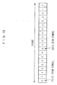
- FIG. 18 is a diagram showing an example of a frame structure. In this case, the data of four pieces of OFDM symbols are transmitted subsequent to two pieces of OFDM pilot symbols.
- the OFDM is capable of greatly suppressing the interference, caused by the multi-paths etc, between the symbols by inserting the GIs. Further, a length of the OFDM symbol is relatively long, resulting in a less decline of the data transmission efficiency due to the insertion of the GIs.
- FIG. 19 is a diagram showing the basic architecture of the MIMO.
- the MIMO provides a plurality of antennas on the transmitting side and the receiving side, respectively (the four antennas are provided on both of the transmitting and receiving sides in FIG. 19).
- the data are received in the form of these pieces of data being mixed together on the receiving side.
- v 0 , v 1 , ..., v N be the reception signals at that time, a relationship can be expressed as by the Formula (1).
- h ij represents a propagation channel from a j-th transmitting antenna to an i-th receiving antenna
- n i represents a noise entering the i-th receiving antenna
- the transmission signal when multiplying the reception signal v by an inverse matrix of a channel matrix, the transmission signal can be restored.
- the MIMO can transmit and receive the plurality of symbols and therefore has a possibility of drastically improving the communication capacity (traffic size).
- respective elements of a matrix H needed for demodulation are estimated from reception signals of known patterns (pilot symbols) that are transmitted sequentially from the individual antennas.
- the signals of the respective antennas can not be separated at a point of estimating the matrix H, and hence the pilot symbols need transmitting by time division.
- the MIMO has poor compatibility with the interference between the codes which is caused by the multi-paths etc, and is therefore utilized in combination with the OFDM system capable of avoiding this problem in many cases.
- the OFDM has the long symbol length, and hence, when combined with the MIMO, if the pilot symbols (pilot signals) of the respective antennas are transmitted by the time division, a period of pilot signal occupying time increases in proportion to the number of the antennas.
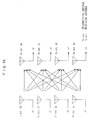
- FIG. 20 is a diagram showing pilot signal transmission timings when combining the MIMO with the OFDM.
- the present invention aims at improving the data transmission efficiency by reducing the time needed for transmitting the pilot signals.
- the present invention adopts the following means in order to solve the problems.
- the present invention is a MIMO-OFDM transmitter comprising a plurality of transmitting antennas transmitting OFDM signals to a receiver, and a generating unit generating direct spreading pilot signals of which pilot data for demodulating the OFDM signals transmitted from the plurality of transmitting antennas in the receiver are spread with direct spreading codes, and transmitting the direct spreading pilot signals from the plurality of transmitting antennas.
- MIMO-OFDM transmitter can be configured such that the generating unit generates the direct spreading pilot signals that are spread with the direct spreading codes each different for every transmitting antenna, and transmits the direct spreading pilot signals at the same transmission timing from the plurality of transmitting antennas.
- the transmitting time of the pilot signals can be reduced down to the pilot signal transmitting time for one operation.
- the data transmission efficiency can be improved by reducing the time required for transmitting the pilot signals.
- a system which combines MIMO with OFDM in a first embodiment, is configured by a MIMO-OFDM transmitter having a plurality of transmitting antennas and a MIMO-OFOM receiver having a plurality of receiving antennas as illustrated in FIG. 19 in the prior art.
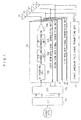
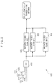
- FIG. 1 is a diagram showing the MIMO-OFDM transmitter in the first embodiment of the present invention.
- the MIMO-OFDM transmitter in the first embodiment includes a serial/parallel converting unit 101, an inverse fast Fourier transform operation unit 102, a plurality of OFDM data signal transmitting units 120, a direct spreading pilot signal transmitting unit 130 and a plurality of transmitting antennas 107.
- the OFDM data signal transmitting units 120 has a guard interval inserting unit 103, a digital/analog converting unit 104, an up-converting unit 105 and an amplifier 106.
- the direct spreading pilot signal transmitting unit 130 has a direct spreading pilot signal generating unit.
- the serial/parallel converting unit 101 converts inputted channel data into a frequency domain data of a subcarrier.
- the serial/parallel converting unit 101 outputs the frequency domain data to the inverse fast Fourier transform operation unit 102.
- the inverse fast Fourier transform (IFFT) operation unit 102 inverse-Fourier-transforms the inputted frequency domain data into time domain data.
- the inverse fast Fourier transform operation unit 102 outputs the time domain data to the OFDM data signal transmitting unit 120 for every transmitting antenna.
- the time domain data inputted to the OFDM data signal transmitting unit 120 per transmitting antenna is inputted to the guard interval inserting unit 103.
- the guard interval inserting unit 103 attaches (inserts), as a guard interval, part of data of the trailing portion of the time domain to the head (of a symbol).
- the data attached with the guard interval is defined as an OFDM symbol.
- the insertion of the guard interval (guard period) can reduce influence of interference, caused by multi-paths, between the OFDM symbols.
- the guard interval inserting unit 103 outputs the OFDM symbol to the digital/analog converting unit 104.
- the digital/analog converting unit 104 converts the OFDM symbol inputted from the guard interval inserting unit 103 into analog signals, and outputs the analog signals to the up-converting unit 105.
- the up-converting unit 105 up-converts the inputted analog signals into high-frequency signals.
- the amplifier 106 amplifies the high-frequency signals and transmits the amplified signals from the respective antennas 107.
- the direct spreading pilot signal generating unit In the direct spreading pilot signal transmitting unit 130, the direct spreading pilot signal generating unit generates direct spreading pilot signals (DS-Pilot), and these pilot signals are transmitted from the respective transmitting antennas.
- DS-Pilot direct spreading pilot signals
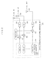
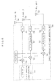
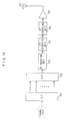
- FIG. 2 is a diagram showing the direct spreading pilot signal generating unit 500 in the direct spreading pilot signal transmitting unit 130 on the transmitting side.
- the MIMO-OFDM transmitter in the first embodiment further includes the direct spreading pilot signal generating unit 500.
- the direct spreading pilot signal generating unit 500 includes a direct spreading code generating unit 510, a multiplying unit 503 that multiplies, by pilot data, the direct spreading code generated by the direct spreading code generating unit 510, and a guard interval inserting unit 505.
- the direct spreading pilot signals generated by the direct spreading pilot signal generating unit 500 are transmitted from individual transmitting antennas 530.
- the direct spreading code generating unit 510 generates individual direct spreading codes (Code #0 through Code #N-1) for every transmitting antenna.
- the multiplying unit 503 multiplies, by the pilot data (the known signal), the direct spreading code per transmitting antenna, which has been generated by the direct spreading code generating unit 510, and outputs a result thereof to the guard interval inserting unit 505.
- the pilot data can involve using data different for every transmitting antenna and also data that is the same with all of the transmitting antennas.
- the guard interval inserting unit 505 attaches (inserts), as the guard interval, part of the tailing portion of the inputted signal to the signal (symbol), thereby organizing the direct spreading pilot signal (pilot symbol). Further, a scheme of attaching none of the guard interval is also available.
- the direct spreading pilot signals generated by the direct spreading pilot signal generating unit 500 are transmitted simultaneously from the respective transmitting antennas 530.
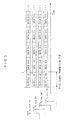
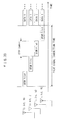
- FIG. 3 is a diagram showing a transmission timing of the pilot signals in the first embodiment.
- Each transmitting antenna is capable of reducing a period of transmitting time of the pilot signals in order to transmit the direct spreading pilot signals simultaneously.
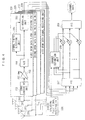
- FIG. 4 is a diagram illustrating the MIMO-OFDM receiver in the first embodiment of the present invention.
- the MIMO-OFDM receiver in the first embodiment includes a plurality of receiving antennas 201, OFDM data signal receiving units 220, a fast Fourier transform operation unit 207, a channel estimation unit 208 and a parallel/serial converting unit 209.
- the data signals received by the respective receiving antennas 201 are inputted to the OFDM data signal receiving units 220 corresponding to the individual receiving antennas 201.
- the data signals inputted to the OFDM data signal receiving units 220 are inputted to a down-converting unit 202.
- the down-converting unit 202 down-converts the high-frequency signals transmitted from the transmitter and received by the receiving antennas 201.
- An AGC (Auto Gain Control) amplifier 203 amplifies the down-converted reception signals.
- An analog/digital converting unit 204 converts the amplified reception signals into digital signals.
- a symbol timing detection unit 205 detects the timing of the OFDM symbol from the guard interval (GI).
- a guard interval removing unit 206 removes the guard intervals inserted by the transmitter from the digital signals.
- the data signals, of which the guard intervals have been removed, are inputted to the fast Fourier transform operation unit 207.
- the fast Fourier transform (FFT) operation unit 207 transforms the digital signals in the time domain into a plurality of subcarrier signals in the frequency domain.
- the channel estimation unit 208 makes channel estimation per subcarrier by use of the data outputted from a direct spreading pilot signal receiving unit 230.
- a channel estimation value obtained by the channel estimation unit 208 is multiplied by the output of the fast Fourier transform operation unit 207, thereby correcting a channel fluctuation.
- the parallel/serial converting unit 209 converts the corrected parallel data into the serial data, thereby obtaining the serial channel data.
- FIG. 5 is a diagram illustrating an example of a configuration for receiving the direct spreading pilot signals based on the separate direct spreading codes given from the respective antennas
- the MIMO-OFDM receiver in the first embodiment further includes a direct spreading pilot signal receiving unit 600.
- the direct spreading pilot signal receiving unit 600 has a guard interval removing unit 605 and a plurality of matched filters 603 corresponding to the direct spreading codes of the respective transmitting antennas.
- the guard interval removing unit 605 removes the guard intervals from the signals received by the receiving antennas 630, and outputs the signals to the matched filters 603.
- the plurality of matched filters 603 wait for the signals with the direct spreading codes corresponding to the respective transmitting antennas.
- a delay profile of each transmitting antenna is obtained by a despreading process based on a replica of the spreading code. This delay profile is outputted to the channel estimation unit 208.
- a channel estimation value of each transmitting antenna can be calculated from the delay profile of each transmitting antenna.
- the direct spreading code generating unit 510 generates the direct spreading code per transmitting antenna.
- the direct spreading pilot signals generated from the direct spreading codes are transmitted simultaneously from the respective transmitting antennas.
- the matched filters 603 wait for the signals with the direct spreading codes generated per transmitting antenna by the direct spreading code generating unit 510.
- the reception signals are inputted to the matched filters 603, the delay profiles for calculating the channel estimation values are obtained from the pilot signals.
- the pilot signals for every transmitting antenna can be organized in a state causing no interference between the pilot signals by spreading the pilot data with the direct spreading codes.
- This scheme enables the pilot signals (FIG. 20) per transmitting antenna, which have hitherto been transmitted by the time division, to be transmitted toward the receiver at the same transmission timing (FIG. 3). This operation makes it possible to reduce the transmitting time of the pilot signals, which have hitherto increased in proportion to the number of antennas, down to the pilot signal transmitting time for one operation.
- the pilot signal involves using the direct spreading pilot signal used for the CDMA method.
- the direct spreading pilot signals using the individual direct spreading codes are transmitted from the respective antennas, thereby enabling the simultaneous transmissions of the pilot signals from the respective transmitting antennas, with the result that the pilot signal transmitting time can be reduced to a great degree.
- the second embodiment has the same configuration as of the first embodiment, and hence the description thereof will be focused mainly on a different point, while the explanations of the common points are omitted.
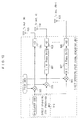
- FIG. 6 is a diagram showing a direct spreading pilot signal generating unit 700.
- the OFDM transmitter in the second embodiment has the same configuration of the MIMO-OFDM transmitter in the first embodiment except a point that the direct spreading pilot signal generating unit has a different configuration.
- the direct spreading pilot signal generating unit 700 includes a direct spreading code generating unit 710, a multiplying unit 703 that multiplies, by the pilot data, the direct spreading code generated by the direct spreading code generating unit 710, a phase shifting unit 707 and a guard interval inserting unit 705.
- the direct spreading pilot signals generated by the direct spreading pilot signal generating unit 700 are transmitted from respective transmitting antennas 730.
- the direct spreading code generating unit 710 generates only one direct spreading code (Code) for all of the transmitting antennas.
- the multiplying unit 703 multiplies, by the pilot data (the known signal), the direct spreading code generated by the direct spreading code generating unit 710.
- the phase shifting unit 707 shifts a phase of the multiplied signal by n/N, and outputs the phase-shifted signal to the guard interval inserting unit 705.
- n represents a serial number of the transmitting antenna
- N represents a total number of the transmitting antennas.
- the phase shift is a process of replacing, in the case of shifting, e.g., a 1/4 phase, a 1/4 tailing portion of the signal and a 3/4 leading portion of the signal with each other.
- FIG. 7 is a diagram showing an example of how the signal is shifted by the 1/4 phase.
- One of the signals multiplied by the multiplying unit 703 is inputted, without being phase-shifted, to the guard interval inserting unit 705.
- the guard interval inserting unit 705 attaches (inserts), as the guard interval, part of the tailing portion of the inputted signal, thereby organizing the direct spreading pilot signal. Further, a scheme of attaching none of the guard interval is also available.
- the direct spreading pilot signals generated by the direct spreading pilot signal generating unit 700 are transmitted simultaneously from the respective transmitting antennas 730.
- the transmission timing of the pilot signal in the second embodiment is the same of the transmission timing of the pilot signal in the first embodiment (FIG. 3).
- the respective transmitting antennas are capable of reducing the transmitting time of the pilot signals because of simultaneously transmitting the direct spreading pilot signals.
- FIG. 8 is a diagram showing an example of a configuration for receiving the direct spreading pilot signals based on the same direct spreading code from the respective antennas.
- the MIMO-OFDM receiver in the second embodiment has the same configuration as of the OFDM receiver in the first embodiment except a point that the direct spreading pilot signal receiving unit has a different configuration.
- a direct spreading pilot signal receiving unit 800 includes a guard interval removing unit 805 and a matched filter 803 corresponding to the direct spreading code.
- the guard interval removing unit 805 removes the guard intervals from the signals received by receiving antennas 83C, and outputs the GI-removed signals to the matched filter 803.
- the matched filter 803 waits for the signals with the direct spreading code generated by the direct spreading code generating unit 710. When the reception signals are inputted to the matched filter 803, the delay profile of each transmitting antenna is acquired. All of the transmitters employ the single direct spreading code, and the delay profiles of all of the transmitters are acquired with the output of the single matched filter.
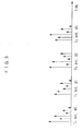
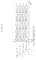
- FIG. 9 is a diagram showing the delay profile obtained by the matched filter.
- a width of the delay profile is well small as compared with a length of the OFDM symbol, and hence, as illustrated in FIG. 9, the delay profiles of the transmitting antennas are acquired in the form of being spaced in time from each other.
- the delay profiles of the individual transmitting antennas can be easily separated according to every transmitting antenna.
- the channel estimation values of the transmitting antennas can be calculated by use of the delay profiles of these individual transmitting antennas.
- the direct spreading code generating unit 710 generates the direct spreading code. Generated also is the direct spreading pilot signal given the phase shift of which quantity is different for every transmitting antenna. This direct spreading pilot signal is transmitted from each transmitting antenna.
- the matched filter 803 waits for the signals with the direct spreading code generated by the direct spreading code generating unit 710.
- the reception signals are inputted to the matched filter 803, the delay profiles of all of the transmitting antennas are obtained.
- the transmitting time of the pilot signals can be reduced. Further, only one matched filter may be sufficient by utilizing the same direct spreading code for all of the transmitting antennas, and hence the device can be simplified.
- the third embodiment has the same configuration as of the first embodiment, and hence the description thereof will be focused mainly on a different point, while the explanations of the common points are omitted.
- FIG. 10 is a diagram showing a direct spreading pilot signal generating unit 900.
- the OFDM transmitter in the third embodiment has the same configuration of the MIMO-OFDM transmitter in the first embodiment except a point that the direct spreading pilot signal generating unit has a different configuration.
- the direct spreading pilot signal generating unit 900 includes a direct spreading code generating unit 910, a multiplying unit 903 that multiplies, by the pilot data, the direct spreading code generated by the direct spreading code generating unit 910, a phase shifting unit 907 and a guard interval inserting unit 905.
- the direct spreading pilot signals generated by the direct spreading pilot signal generating unit 900 are transmitted from respective transmitting antennas 930.
- the direct spreading code generating unit 910 generates only one direct spreading code for all of the transmitting antennas.
- the direct spreading code involves using a code such as an M-sequence (maximum length sequence) code exhibiting a good autocorrelation (the M-sequence code is applied in the third embodiment).
- FIG. 12 is a diagram showing a characteristic of the autocorrelation of the M-sequence code having a code length 127. In the case of taking the autocorrelation of the code length 127, the code length comes to 127 when perfectly in phase and becomes -1 when the phase is shifted.
- the phase shifting unit 907 shifts a phase of the multiplied signal by n/N, and outputs the phase-shifted signal to the guard interval inserting unit 905.
- n represents a serial number of the transmitting antenna
- N represents a total number of the transmitting antennas.
- the phase shift is the same process as in the second embodiment.
- One of the signals multiplied by the multiplying unit 903 is inputted, without being phase-shifted, to the guard interval inserting unit 905.
- the guard interval inserting unit 905 attaches (inserts), as the guard interval, part of the tailing portion of the inputted signal, thereby organizing the direct spreading pilot signal. Further, the scheme of attaching none of the guard interval is also available.
- the direct spreading pilot signals generated by the direct spreading pilot signal generating unit 900 are transmitted simultaneously from the respective transmitting antennas 930.
- the transmission timing of the pilot signal in the third embodiment is the same of the transmission timing of the pilot signal in the first embodiment.
- the respective transmitting antennas are capable of reducing the transmitting time of the pilot signals because of simultaneously transmitting the direct spreading pilot signals.
- FIG. 11 is a diagram showing an example of a configuration for receiving the direct spreading pilot signals based on the same direct spreading code from the respective antennas.
- the MIMO-OFDM receiver in the third embodiment has the same configuration as of the OFDM receiver in the first embodiment except a point that the direct spreading pilot signal receiving unit has a different configuration.
- a direct spreading pilot signal receiving unit 1000 includes a guard interval removing unit 1005 and a matched filter 1003 corresponding to the direct spreading code M-sequence code).
- the guard interval removing unit 1005 removes the guard intervals from the signals received by receiving antennas 1030, and outputs the GI-removed signals to the matched filter 1003.
- the matched filter 1003 waits for the signals with the direct spreading code (M-sequence code) generated by the direct spreading code generating unit 910.
- M-sequence code the direct spreading code generated by the direct spreading code generating unit 910.
- the delay profile obtained by the matched filter 1003 is the same as the delay profile (FIG. 9) obtained by the matched filter 803 in the second embodiment.
- the channel estimation value of each transmitting antenna can be calculated from the delay profile of each transmitting antenna.
- the direct spreading code generating unit 910 generates the direct spreading code (M-sequence code). Generated also is the direct spreading pilot signal that is phase-shifted with a quantity different for every transmitting antenna. The direct spreading pilot signals are transmitted simultaneously from the respective transmitting antennas.
- the matched filter 1003 waits for the signals with the direct spreading code (M-sequence code) generated by the direct spreading code generating unit 910.
- the direct spreading code M-sequence code
- the transmitting time of the pilot signals can be reduced. Moreover, all of the transmitting antennas use the same direct spreading code, and hence only one matched filter may be sufficient, whereby the device can be simplified. Further, the M-sequence code has the preferable autocorrelation characteristic, thereby restraining the interference between the signals and improving accuracy of the delay profile obtained by the matched filter 1003.
- the fourth embodiment has the same configuration as of the first embodiment, and therefore the description thereof will be focused mainly on a different point, while the explanations of the common points are omitted.
- the transmitter in the fourth embodiment further has the same configuration as of the MIMO-OFDM transmitter in the first embodiment.
- the pilot data to be used involve employing the data shorter than a length of the OFDM symbol.
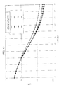
- FIG. 13 is a graph showing a BER (Bit Error Rate) characteristic when decreasing a length of the direct spreading pilot signal to be used.
- FIG. 13 shows the BER characteristic when employing the direct spreading pilot signals having a code length 512, a code length 256, a code length 128 and a code length 64 with respect to an OFDM symbol length 512 .
- BER Bit Error Rate
- FIG. 14 is a diagram showing the transmission timing when using the short direct spreading pilot signals.
- the short direct spreading pilot signals are transmitted by the time division, whereby the transmitting time of the pilot signals can be reduced.
- the length of the signal direct spreading pilot signal is set to 1/4 of the OFDM symbol length.
- the total time for transmitting the direct spreading pilot signals from all of the transmitting antennas is equalized to the OFDM symbol length. This contrivance enables the data transmission timings delimited at the same interval.
- the short direct spreading pilot signals are transmitted simultaneously from the respective transmitting antennas, thereby making it possible to further decrease the transmitting time of the pilot signals.
- FIG. 15 is a diagram showing the transmission timings when the short direct spreading pilot signals are transmitted simultaneously from the respective transmitting antennas.
- the receiver in the fourth embodiment can have the same configuration as of the MIMO-OFDM receiver in the first embodiment.
- the OFDM transmitter generates the direct spreading pilot signal shorter than the OFDM symbol length.
- the OFDM transmitter takes the same configuration as in the first embodiment and is thereby capable of transmitting the direct spreading pilot signals each shorter than the OFDM symbol length simultaneously from the respective transmitting antennas.
- the transmitting time of the pilot signals can be further reduced.
Landscapes
- Engineering & Computer Science (AREA)
- Signal Processing (AREA)
- Computer Networks & Wireless Communication (AREA)
- Power Engineering (AREA)
- Radio Transmission System (AREA)
Abstract
Description
- The present invention relates to a channel estimation method used for digital communications. The present invention relates particularly to a configuration of pilot channels or to a channel estimation unit in a wireless system that combines MIMO (Multi Input Multi Output) and OFDM (Orthogonal Frequency Division Multiplexing) with each other.
- There have been active researches and studies of a high-speed/large-capacity mobile communication system over the recent years, and the attention has been paid to a system that combines the MIMO and the OFDM with each other as a basic system thereof.
- FIG. 16 is a diagram showing a basic configuration of an OFDM transmitter in an OFDM transmission system. Transmission data are mapped as frequency domain data of respective subcarriers by serial/parallel conversion. The frequency domain data undergo inverse Fourier transform into time domain waveform data. Transmitted next is an OFDM symbol organized by attaching (inserting), as a guard interval (GI), part of data of the trailing portion of this time domain to the head (of the symbol).
- Herein, an in-depth description of the OFDM transmitter in FIG. 16 is given. A serial/parallel converting
unit 101 converts inputted channel data into a frequency domain data of a subcarrier. The serial/parallel converting unit 101 outputs the frequency domain data to an inverse fast Fouriertransform operation unit 102. The inverse fast Fourier transform (IFFT)operation unit 102 inverse-Fourier-transforms the inputted frequency domain data into time domain data. The inverse fast Fouriertransform operation unit 102 outputs the time domain data to a guardinterval inserting unit 103. The guardinterval inserting unit 103 attaches (inserts), as the guard interval, part of data of the trailing portion of the time domain to the head (of the symbol). The data attached with the guard interval is defined as an OFDM symbol. The insertion of the guard interval (guard period) can reduce influence of interference, caused by multi-paths, between the OFDM symbols. The guardinterval inserting unit 103 outputs the OFDM symbol to a digital/analog converting unit 104. The digital/analog converting unit 104 converts the OFDM symbol inputted from the guardinterval inserting unit 103 into analog signals, and outputs the analog signals to an up-convertingunit 105. The up-convertingunit 105 up-converts the inputted analog signals into high-frequency signals. Anamplifier 106 amplifies the high-frequency signals and transmits the amplified signals from therespective antennas 107. - FIG. 17 is a diagram showing a basic configuration of the OFDM receiver in the OFDM transmission system. The received time domain signals undergo extracting the individual OFDM symbols and removing the guard intervals (GIs) at the symbol timings obtained from the correlations of the guard intervals. The GI-removed signals are subjected to fast Fourier transform (FFT) and are thereby separated into the signals according to the subcarrier. The channel estimation unit obtains a channel estimation value for every subcarrier, and channel correction per subcarrier is conducted based on the channel estimation value, thereby obtaining a symbol value per subcarrier.
- Herein, the OFDM received in FIG. 17 will be explained in detail. A down-converting
unit 202 down-converts the high-frequency signals transmitted from the transmitter and received by thereceiving antennas 201. An AGC (Auto Gain Control)amplifier 203 amplifies the down-converted reception signals. An analog/digital converting unit 204 converts the amplified reception signals into digital signals. A symboltiming detection unit 205 detects the timing of the OFDM symbol from the guard interval (GI). A guardinterval removing unit 206 removes the guard intervals inserted by the transmitter from the digital signals. - A fast Fourier transform (FFT)
operation unit 207 transforms the digital signals in the time domain into a plurality of subcarrier signals in the frequency domain. Achannel estimation unit 208 makes channel estimation per subcarrier by use of the pilot signals that are time-multiplexed by the transmitter. A channel estimation value obtained by thechannel estimation unit 208 is multiplied by an output of the fast Fouriertransform operation unit 207, thereby correcting a channel fluctuation. A parallel/serial convertingunit 209 converts the corrected parallel data into the serial data, thereby obtaining the serial channel data. - The channel estimation value is obtained from the pilot symbol of the known signals. FIG. 18 is a diagram showing an example of a frame structure. In this case, the data of four pieces of OFDM symbols are transmitted subsequent to two pieces of OFDM pilot symbols.
- The OFDM is capable of greatly suppressing the interference, caused by the multi-paths etc, between the symbols by inserting the GIs. Further, a length of the OFDM symbol is relatively long, resulting in a less decline of the data transmission efficiency due to the insertion of the GIs.
- FIG. 19 is a diagram showing the basic architecture of the MIMO. The MIMO provides a plurality of antennas on the transmitting side and the receiving side, respectively (the four antennas are provided on both of the transmitting and receiving sides in FIG. 19). When different pieces of data s0, s1,..., sN are transmitted from the respective antennas on the transmitting side, the data are received in the form of these pieces of data being mixed together on the receiving side. Let v0, v1, ..., vN be the reception signals at that time, a relationship can be expressed as by the Formula (1).
-

- Here, hij represents a propagation channel from a j-th transmitting antenna to an i-th receiving antenna, and ni represents a noise entering the i-th receiving antenna. To give a vector notation, this is expressed by the Formula (2).
-

- Here, when multiplying the reception signal v by an inverse matrix of a channel matrix, the transmission signal can be restored.
-

- Thus, the MIMO can transmit and receive the plurality of symbols and therefore has a possibility of drastically improving the communication capacity (traffic size). Herein, respective elements of a matrix H needed for demodulation are estimated from reception signals of known patterns (pilot symbols) that are transmitted sequentially from the individual antennas. The signals of the respective antennas can not be separated at a point of estimating the matrix H, and hence the pilot symbols need transmitting by time division.
- The MIMO has poor compatibility with the interference between the codes which is caused by the multi-paths etc, and is therefore utilized in combination with the OFDM system capable of avoiding this problem in many cases.
- [Patent document 1] Japanese Patent Application Laid-Open Publication
No.2005-110130 - [Patent document 2]
Japanese Patent Application Laid-Open Publication No.2004-253925 - [Patent document 3] Patent Publication for
WO 2005/011167 - The OFDM has the long symbol length, and hence, when combined with the MIMO, if the pilot symbols (pilot signals) of the respective antennas are transmitted by the time division, a period of pilot signal occupying time increases in proportion to the number of the antennas. FIG. 20 is a diagram showing pilot signal transmission timings when combining the MIMO with the OFDM. When transmitting the OFDM pilot signal from the single antennal, none of the signals can be transmitted from other antennas, so that the transmitting time of the OFDM pilot signals increases in proportion to the number of the antennas. Hence, the data transmission efficiency declines. If a rate of transmitting the pilot signals is reduced, the transmission efficiency can be improved, however, it is difficult to follow a propagation environment that changes fast as in the case of the mobile communications.
- Such being the case, the present invention aims at improving the data transmission efficiency by reducing the time needed for transmitting the pilot signals.
- The present invention adopts the following means in order to solve the problems.
- Namely, the present invention is a MIMO-OFDM transmitter comprising a plurality of transmitting antennas transmitting OFDM signals to a receiver, and a generating unit generating direct spreading pilot signals of which pilot data for demodulating the OFDM signals transmitted from the plurality of transmitting antennas in the receiver are spread with direct spreading codes, and transmitting the direct spreading pilot signals from the plurality of transmitting antennas.
- Further, in the present invention, MIMO-OFDM transmitter can be configured such that the generating unit generates the direct spreading pilot signals that are spread with the direct spreading codes each different for every transmitting antenna, and transmits the direct spreading pilot signals at the same transmission timing from the plurality of transmitting antennas.
- According to the present invention, the transmitting time of the pilot signals can be reduced down to the pilot signal transmitting time for one operation.
- According to the present invention, the data transmission efficiency can be improved by reducing the time required for transmitting the pilot signals.
-
- FIG. 1 is a diagram showing an example of a configuration of a MIMO-OFDM transmitter according to an embodiment of the present invention.
- FIG. 2 is a diagram showing an example of a configuration for transmitting direct spreading pilot signals based on different codes via respective antennas.
- FIG. 3 is a diagram showing pilot signal transmission timings when using the direct spreading pilot signals.
- FIG. 4 is a diagram showing an example of a configuration of a MIMO-OFDM receiver according to the embodiment of the present invention.
- FIG. 5 is a diagram showing an example of a configuration for receiving the direct spreading pilot signals based on the different codes from the respective antennas.
- FIG. 6 is a diagram showing an example of a configuration for transmitting the direct spreading pilot signals each having a different shift quantity from the respective antennas.
- FIG.7 is a diagram showing an example of a 1/4 phase-shift of the direct spreading pilot signal.
- FIG.8 is a diagram showing an example of a configuration for receiving the direct spreading pilot signals each having the different shift quantity from the respective antennas.
- FIG.9 is a diagram showing an example of an output of a matched filter on the receiving side when four pieces of transmitting antennas are provided.
- FIG.10 is a diagram illustrating an example of a configuration for transmitting the direct spreading pilot signals using an M-sequence code.
- FIG.11 is a diagram illustrating an example of a configuration for receiving the direct spreading pilot signals based on the same direct spreading code (M-sequence code) from the respective antennas.
- FIG. 12 is a graph showing an autocorrelation characteristic of the M-sequence code having a
code length 127. - FIG. 13 is a graph showing a BER characteristic when using short direct spreading pilot signals.
- FIG. 14 is a diagram showing transmission timings when employing the short direct spreading pilot signals.
- FIG. 15 is a diagram showing transmission timings when multiplexing the short direct spreading pilot signals.
- FIG. 16 is a diagram showing an example of a configuration of an OFDM transmitter in an OFDM transmission system.
- FIG. 17 is a diagram showing an example of a configuration of an OFDM receiver in the OFDM transmission system.
- FIG. 18 is a diagram showing an example of a frame structure.
- FIG. 19 is a diagram showing a MIMO architecture.
- FIG. 20 is a diagram showing the transmission timings of the pilot signals when combining MIMO and OFDM with each other.
- An embodiment of the present invention will hereinafter be described with reference to the drawings. Configurations in the following embodiments are exemplifications, and the present invention is not limited to the configurations in the embodiments.
- A system, which combines MIMO with OFDM in a first embodiment, is configured by a MIMO-OFDM transmitter having a plurality of transmitting antennas and a MIMO-OFOM receiver having a plurality of receiving antennas as illustrated in FIG. 19 in the prior art.
- FIG. 1 is a diagram showing the MIMO-OFDM transmitter in the first embodiment of the present invention. The MIMO-OFDM transmitter in the first embodiment includes a serial/parallel converting
unit 101, an inverse fast Fouriertransform operation unit 102, a plurality of OFDM data signal transmittingunits 120, a direct spreading pilotsignal transmitting unit 130 and a plurality of transmittingantennas 107. The OFDM data signal transmittingunits 120 has a guardinterval inserting unit 103, a digital/analog converting unit 104, an up-convertingunit 105 and anamplifier 106. The direct spreading pilotsignal transmitting unit 130 has a direct spreading pilot signal generating unit. - The serial/parallel converting
unit 101 converts inputted channel data into a frequency domain data of a subcarrier. The serial/parallel convertingunit 101 outputs the frequency domain data to the inverse fast Fouriertransform operation unit 102. The inverse fast Fourier transform (IFFT)operation unit 102 inverse-Fourier-transforms the inputted frequency domain data into time domain data. The inverse fast Fouriertransform operation unit 102 outputs the time domain data to the OFDM data signal transmittingunit 120 for every transmitting antenna. - The time domain data inputted to the OFDM data signal transmitting
unit 120 per transmitting antenna is inputted to the guardinterval inserting unit 103. The guardinterval inserting unit 103 attaches (inserts), as a guard interval, part of data of the trailing portion of the time domain to the head (of a symbol). The data attached with the guard interval is defined as an OFDM symbol. The insertion of the guard interval (guard period) can reduce influence of interference, caused by multi-paths, between the OFDM symbols. The guardinterval inserting unit 103 outputs the OFDM symbol to the digital/analog converting unit 104. The digital/analog converting unit 104 converts the OFDM symbol inputted from the guardinterval inserting unit 103 into analog signals, and outputs the analog signals to the up-convertingunit 105. The up-convertingunit 105 up-converts the inputted analog signals into high-frequency signals. Theamplifier 106 amplifies the high-frequency signals and transmits the amplified signals from therespective antennas 107. - In the direct spreading pilot
signal transmitting unit 130, the direct spreading pilot signal generating unit generates direct spreading pilot signals (DS-Pilot), and these pilot signals are transmitted from the respective transmitting antennas. - FIG. 2 is a diagram showing the direct spreading pilot
signal generating unit 500 in the direct spreading pilotsignal transmitting unit 130 on the transmitting side. The MIMO-OFDM transmitter in the first embodiment further includes the direct spreading pilotsignal generating unit 500. - The direct spreading pilot
signal generating unit 500 includes a direct spreadingcode generating unit 510, a multiplyingunit 503 that multiplies, by pilot data, the direct spreading code generated by the direct spreadingcode generating unit 510, and a guardinterval inserting unit 505. The direct spreading pilot signals generated by the direct spreading pilotsignal generating unit 500 are transmitted from individual transmittingantennas 530. - The direct spreading
code generating unit 510 generates individual direct spreading codes (Code # 0 through Code #N-1) for every transmitting antenna. The multiplyingunit 503 multiplies, by the pilot data (the known signal), the direct spreading code per transmitting antenna, which has been generated by the direct spreadingcode generating unit 510, and outputs a result thereof to the guardinterval inserting unit 505. The pilot data can involve using data different for every transmitting antenna and also data that is the same with all of the transmitting antennas. The guardinterval inserting unit 505 attaches (inserts), as the guard interval, part of the tailing portion of the inputted signal to the signal (symbol), thereby organizing the direct spreading pilot signal (pilot symbol). Further, a scheme of attaching none of the guard interval is also available. - The direct spreading pilot signals generated by the direct spreading pilot
signal generating unit 500 are transmitted simultaneously from therespective transmitting antennas 530. - FIG. 3 is a diagram showing a transmission timing of the pilot signals in the first embodiment. Each transmitting antenna is capable of reducing a period of transmitting time of the pilot signals in order to transmit the direct spreading pilot signals simultaneously.
- FIG. 4 is a diagram illustrating the MIMO-OFDM receiver in the first embodiment of the present invention. The MIMO-OFDM receiver in the first embodiment includes a plurality of receiving
antennas 201, OFDM data signal receivingunits 220, a fast Fouriertransform operation unit 207, achannel estimation unit 208 and a parallel/serial convertingunit 209. - The data signals received by the respective receiving
antennas 201 are inputted to the OFDM data signal receivingunits 220 corresponding to theindividual receiving antennas 201. The data signals inputted to the OFDM data signal receivingunits 220 are inputted to a down-convertingunit 202. The down-convertingunit 202 down-converts the high-frequency signals transmitted from the transmitter and received by the receivingantennas 201. An AGC (Auto Gain Control)amplifier 203 amplifies the down-converted reception signals. An analog/digital convertingunit 204 converts the amplified reception signals into digital signals. A symboltiming detection unit 205 detects the timing of the OFDM symbol from the guard interval (GI). A guardinterval removing unit 206 removes the guard intervals inserted by the transmitter from the digital signals. The data signals, of which the guard intervals have been removed, are inputted to the fast Fouriertransform operation unit 207. - The fast Fourier transform (FFT)
operation unit 207 transforms the digital signals in the time domain into a plurality of subcarrier signals in the frequency domain. Thechannel estimation unit 208 makes channel estimation per subcarrier by use of the data outputted from a direct spreading pilotsignal receiving unit 230. A channel estimation value obtained by thechannel estimation unit 208 is multiplied by the output of the fast Fouriertransform operation unit 207, thereby correcting a channel fluctuation. The parallel/serial convertingunit 209 converts the corrected parallel data into the serial data, thereby obtaining the serial channel data. - FIG. 5 is a diagram illustrating an example of a configuration for receiving the direct spreading pilot signals based on the separate direct spreading codes given from the respective antennas The MIMO-OFDM receiver in the first embodiment further includes a direct spreading pilot
signal receiving unit 600. - The direct spreading pilot
signal receiving unit 600 has a guardinterval removing unit 605 and a plurality of matchedfilters 603 corresponding to the direct spreading codes of the respective transmitting antennas. - The guard
interval removing unit 605 removes the guard intervals from the signals received by the receivingantennas 630, and outputs the signals to the matched filters 603. The plurality of matchedfilters 603 wait for the signals with the direct spreading codes corresponding to the respective transmitting antennas. When the reception signals are inputted to these matchedfilters 603, a delay profile of each transmitting antenna is obtained by a despreading process based on a replica of the spreading code. This delay profile is outputted to thechannel estimation unit 208. A channel estimation value of each transmitting antenna can be calculated from the delay profile of each transmitting antenna. - According to the first embodiment discussed so far, in the direct spreading pilot
signal generating unit 500, the direct spreadingcode generating unit 510 generates the direct spreading code per transmitting antenna. The direct spreading pilot signals generated from the direct spreading codes are transmitted simultaneously from the respective transmitting antennas. - In the direct spreading pilot
signal receiving unit 600, the matchedfilters 603 wait for the signals with the direct spreading codes generated per transmitting antenna by the direct spreadingcode generating unit 510. When the reception signals are inputted to the matchedfilters 603, the delay profiles for calculating the channel estimation values are obtained from the pilot signals. - according to the first embodiment, the pilot signals for every transmitting antenna can be organized in a state causing no interference between the pilot signals by spreading the pilot data with the direct spreading codes. This scheme enables the pilot signals (FIG. 20) per transmitting antenna, which have hitherto been transmitted by the time division, to be transmitted toward the receiver at the same transmission timing (FIG. 3). This operation makes it possible to reduce the transmitting time of the pilot signals, which have hitherto increased in proportion to the number of antennas, down to the pilot signal transmitting time for one operation.
- Namely, according to the first embodiment, the pilot signal involves using the direct spreading pilot signal used for the CDMA method. To be specific, the direct spreading pilot signals using the individual direct spreading codes are transmitted from the respective antennas, thereby enabling the simultaneous transmissions of the pilot signals from the respective transmitting antennas, with the result that the pilot signal transmitting time can be reduced to a great degree.
- Next, a second embodiment of the present invention will be described. The second embodiment has the same configuration as of the first embodiment, and hence the description thereof will be focused mainly on a different point, while the explanations of the common points are omitted.
- FIG. 6 is a diagram showing a direct spreading pilot
signal generating unit 700. The OFDM transmitter in the second embodiment has the same configuration of the MIMO-OFDM transmitter in the first embodiment except a point that the direct spreading pilot signal generating unit has a different configuration. - The direct spreading pilot
signal generating unit 700 includes a direct spreadingcode generating unit 710, a multiplyingunit 703 that multiplies, by the pilot data, the direct spreading code generated by the direct spreadingcode generating unit 710, aphase shifting unit 707 and a guardinterval inserting unit 705. The direct spreading pilot signals generated by the direct spreading pilotsignal generating unit 700 are transmitted from respective transmittingantennas 730. - The direct spreading
code generating unit 710 generates only one direct spreading code (Code) for all of the transmitting antennas. The multiplyingunit 703 multiplies, by the pilot data (the known signal), the direct spreading code generated by the direct spreadingcode generating unit 710. - The
phase shifting unit 707 shifts a phase of the multiplied signal by n/N, and outputs the phase-shifted signal to the guardinterval inserting unit 705. Herein, "n" represents a serial number of the transmitting antenna, and "N" represents a total number of the transmitting antennas. The phase shift is a process of replacing, in the case of shifting, e.g., a 1/4 phase, a 1/4 tailing portion of the signal and a 3/4 leading portion of the signal with each other. FIG. 7 is a diagram showing an example of how the signal is shifted by the 1/4 phase. One of the signals multiplied by the multiplyingunit 703 is inputted, without being phase-shifted, to the guardinterval inserting unit 705. - The guard
interval inserting unit 705 attaches (inserts), as the guard interval, part of the tailing portion of the inputted signal, thereby organizing the direct spreading pilot signal. Further, a scheme of attaching none of the guard interval is also available. - The direct spreading pilot signals generated by the direct spreading pilot
signal generating unit 700 are transmitted simultaneously from therespective transmitting antennas 730. - The transmission timing of the pilot signal in the second embodiment is the same of the transmission timing of the pilot signal in the first embodiment (FIG. 3). The respective transmitting antennas are capable of reducing the transmitting time of the pilot signals because of simultaneously transmitting the direct spreading pilot signals.
- FIG. 8 is a diagram showing an example of a configuration for receiving the direct spreading pilot signals based on the same direct spreading code from the respective antennas. The MIMO-OFDM receiver in the second embodiment has the same configuration as of the OFDM receiver in the first embodiment except a point that the direct spreading pilot signal receiving unit has a different configuration.
- A direct spreading pilot signal receiving unit 800 includes a guard
interval removing unit 805 and a matchedfilter 803 corresponding to the direct spreading code. - The guard
interval removing unit 805 removes the guard intervals from the signals received by receiving antennas 83C, and outputs the GI-removed signals to the matchedfilter 803. The matchedfilter 803 waits for the signals with the direct spreading code generated by the direct spreadingcode generating unit 710. When the reception signals are inputted to the matchedfilter 803, the delay profile of each transmitting antenna is acquired. All of the transmitters employ the single direct spreading code, and the delay profiles of all of the transmitters are acquired with the output of the single matched filter. - FIG. 9 is a diagram showing the delay profile obtained by the matched filter. Generally, a width of the delay profile is well small as compared with a length of the OFDM symbol, and hence, as illustrated in FIG. 9, the delay profiles of the transmitting antennas are acquired in the form of being spaced in time from each other. The delay profiles of the individual transmitting antennas can be easily separated according to every transmitting antenna. The channel estimation values of the transmitting antennas can be calculated by use of the delay profiles of these individual transmitting antennas.
- According to the second embodiment discussed so far, in the direct spreading pilot
signal generating unit 700, the direct spreadingcode generating unit 710 generates the direct spreading code. Generated also is the direct spreading pilot signal given the phase shift of which quantity is different for every transmitting antenna. This direct spreading pilot signal is transmitted from each transmitting antenna. - In the direct spreading pilot signal receiving unit 800, the matched
filter 803 waits for the signals with the direct spreading code generated by the direct spreadingcode generating unit 710. When the reception signals are inputted to the matchedfilter 803, the delay profiles of all of the transmitting antennas are obtained. - According to the second embodiment, the transmitting time of the pilot signals can be reduced. Further, only one matched filter may be sufficient by utilizing the same direct spreading code for all of the transmitting antennas, and hence the device can be simplified.
- Next, a third embodiment of the present invention will be described. The third embodiment has the same configuration as of the first embodiment, and hence the description thereof will be focused mainly on a different point, while the explanations of the common points are omitted.
- FIG. 10 is a diagram showing a direct spreading pilot signal generating unit 900. The OFDM transmitter in the third embodiment has the same configuration of the MIMO-OFDM transmitter in the first embodiment except a point that the direct spreading pilot signal generating unit has a different configuration. The direct spreading pilot signal generating unit 900 includes a direct spreading
code generating unit 910, a multiplyingunit 903 that multiplies, by the pilot data, the direct spreading code generated by the direct spreadingcode generating unit 910, aphase shifting unit 907 and a guardinterval inserting unit 905. The direct spreading pilot signals generated by the direct spreading pilot signal generating unit 900 are transmitted from respective transmittingantennas 930. - The direct spreading
code generating unit 910 generates only one direct spreading code for all of the transmitting antennas. Herein, the direct spreading code involves using a code such as an M-sequence (maximum length sequence) code exhibiting a good autocorrelation (the M-sequence code is applied in the third embodiment). FIG. 12 is a diagram showing a characteristic of the autocorrelation of the M-sequence code having acode length 127. In the case of taking the autocorrelation of thecode length 127, the code length comes to 127 when perfectly in phase and becomes -1 when the phase is shifted. - The
phase shifting unit 907 shifts a phase of the multiplied signal by n/N, and outputs the phase-shifted signal to the guardinterval inserting unit 905. Herein, "n" represents a serial number of the transmitting antenna, and "N" represents a total number of the transmitting antennas. The phase shift is the same process as in the second embodiment. One of the signals multiplied by the multiplyingunit 903 is inputted, without being phase-shifted, to the guardinterval inserting unit 905. - The guard
interval inserting unit 905 attaches (inserts), as the guard interval, part of the tailing portion of the inputted signal, thereby organizing the direct spreading pilot signal. Further, the scheme of attaching none of the guard interval is also available. - The direct spreading pilot signals generated by the direct spreading pilot signal generating unit 900 are transmitted simultaneously from the
respective transmitting antennas 930. - The transmission timing of the pilot signal in the third embodiment is the same of the transmission timing of the pilot signal in the first embodiment. The respective transmitting antennas are capable of reducing the transmitting time of the pilot signals because of simultaneously transmitting the direct spreading pilot signals.
- FIG. 11 is a diagram showing an example of a configuration for receiving the direct spreading pilot signals based on the same direct spreading code from the respective antennas. The MIMO-OFDM receiver in the third embodiment has the same configuration as of the OFDM receiver in the first embodiment except a point that the direct spreading pilot signal receiving unit has a different configuration.
- A direct spreading pilot
signal receiving unit 1000 includes a guardinterval removing unit 1005 and a matchedfilter 1003 corresponding to the direct spreading code M-sequence code). - The guard
interval removing unit 1005 removes the guard intervals from the signals received by receivingantennas 1030, and outputs the GI-removed signals to the matchedfilter 1003. The matchedfilter 1003 waits for the signals with the direct spreading code (M-sequence code) generated by the direct spreadingcode generating unit 910. When the reception signals are inputted to the matchedfilter 1003, the delay profile of each transmitting antenna is acquired. All of the transmitters employ the single direct spreading code (M-sequence code), and the delay profiles of all of the transmitters are acquired with the output of the single matched filter. - The delay profile obtained by the matched
filter 1003 is the same as the delay profile (FIG. 9) obtained by the matchedfilter 803 in the second embodiment. The channel estimation value of each transmitting antenna can be calculated from the delay profile of each transmitting antenna. - According to the embodiment discussed so far, in the direct spreading pilot signal generating unit 900, the direct spreading
code generating unit 910 generates the direct spreading code (M-sequence code). Generated also is the direct spreading pilot signal that is phase-shifted with a quantity different for every transmitting antenna. The direct spreading pilot signals are transmitted simultaneously from the respective transmitting antennas. - In the direct spreading pilot
signal receiving unit 1000, the matchedfilter 1003 waits for the signals with the direct spreading code (M-sequence code) generated by the direct spreadingcode generating unit 910. When the reception signals are inputted to the matchedfilter 1003, the delay profiles of all of the transmitting antennas are obtained. - According to the third embodiment, the transmitting time of the pilot signals can be reduced. Moreover, all of the transmitting antennas use the same direct spreading code, and hence only one matched filter may be sufficient, whereby the device can be simplified. Further, the M-sequence code has the preferable autocorrelation characteristic, thereby restraining the interference between the signals and improving accuracy of the delay profile obtained by the matched
filter 1003. - Next, a fourth embodiment of the present invention will be described. The fourth embodiment has the same configuration as of the first embodiment, and therefore the description thereof will be focused mainly on a different point, while the explanations of the common points are omitted.
- The transmitter in the fourth embodiment further has the same configuration as of the MIMO-OFDM transmitter in the first embodiment. The pilot data to be used, however, involve employing the data shorter than a length of the OFDM symbol.
- FIG. 13 is a graph showing a BER (Bit Error Rate) characteristic when decreasing a length of the direct spreading pilot signal to be used. FIG. 13 shows the BER characteristic when employing the direct spreading pilot signals having a
code length 512, acode length 256, acode length 128 and acode length 64 with respect to anOFDM symbol length 512 . At an operating point given by BER = 0.1, for instance, even when shortened to, e.g., thelength 128 corresponding to 1/4 of the OFDM symbol length, it is understood that there is almost no change when the code length is 512. Namely, it is possible to restrain a decline of the BER characteristic even by using the short direct spreading pilot signal generated by employing the short pilot data. - FIG. 14 is a diagram showing the transmission timing when using the short direct spreading pilot signals. The short direct spreading pilot signals are transmitted by the time division, whereby the transmitting time of the pilot signals can be reduced.
- Further, when, e.g., four pieces of transmitting antennas are provided, the length of the signal direct spreading pilot signal is set to 1/4 of the OFDM symbol length. At this time, the total time for transmitting the direct spreading pilot signals from all of the transmitting antennas is equalized to the OFDM symbol length. This contrivance enables the data transmission timings delimited at the same interval.
- Moreover, as in the first embodiment, the short direct spreading pilot signals are transmitted simultaneously from the respective transmitting antennas, thereby making it possible to further decrease the transmitting time of the pilot signals. FIG. 15 is a diagram showing the transmission timings when the short direct spreading pilot signals are transmitted simultaneously from the respective transmitting antennas.
- The receiver in the fourth embodiment can have the same configuration as of the MIMO-OFDM receiver in the first embodiment.
- According to the fourth embodiment discussed so far, the OFDM transmitter generates the direct spreading pilot signal shorter than the OFDM symbol length.
- With this operation, the transmitting time of the pilot signals can be reduced.
- Moreover, the OFDM transmitter takes the same configuration as in the first embodiment and is thereby capable of transmitting the direct spreading pilot signals each shorter than the OFDM symbol length simultaneously from the respective transmitting antennas.
- According to the fourth embodiment, the transmitting time of the pilot signals can be further reduced.
Claims (7)
- A MIMO-OFDM transmitter comprising:a plurality of transmitting antennas transmitting OFDM signals to a receiver; anda generating unit generating direct spreading pilot signals of which pilot data for demodulating the OFDM signals transmitted from the plurality of transmitting antennas in the receiver are spread with direct spreading codes, and transmitting the direct spreading pilot signals from the plurality of transmitting antennas.
- A MIMO-OFDM transmitter according to Claim 1, wherein the generating unit generates the direct spreading pilot signals that are spread with the direct spreading codes each different for every transmitting antenna, and transmits the direct spreading pilot signals at the same transmission timing from the plurality of transmitting antennas.
- A MIMO-OFDM transmitter according to Claim 1, wherein the generating unit generates the direct spreading pilot signal per transmitting antenna that has a length of transmitting time shorter than the transmission time of one OFDM signal, and transmits the direct spreading pilot signals by time division from the plurality of transmitting antennas.
- A MIMO-OFDM transmitter according to Claim 1, wherein the generating unit generates the direct spreading pilot signal per transmitting antenna that has a length of transmitting time shorter than the transmission time of one OFDM signal, and transmits the direct spreading pilot signals at the same transmission timing from the plurality of transmitting antennas.
- A MIMO-OFDM transmitter according to Claim 1, wherein the generating unit gives a predetermined phase shift per transmitting antenna to the pilot data that are spread with the same direct spreading code, and thereafter transmits the pilot signals from the plurality of transmitting antennas.
- A MIMO-OFDM transmitter according to Claim 5, wherein the same direct spreading code is an M-sequence (maximum length sequence) code.
- A MIMO-OFDM transmitter according to any of the preceding claims, wherein the generating unit attaches guard intervals to within the direct spreading pilot signals.
Applications Claiming Priority (1)
| Application Number | Priority Date | Filing Date | Title |
|---|---|---|---|
| JP2006126537A JP2007300383A (en) | 2006-04-28 | 2006-04-28 | MIMO-OFDM transmitter |
Publications (3)
| Publication Number | Publication Date |
|---|---|
| EP1850549A2 true EP1850549A2 (en) | 2007-10-31 |
| EP1850549A3 EP1850549A3 (en) | 2013-05-29 |
| EP1850549B1 EP1850549B1 (en) | 2016-01-13 |
Family
ID=38293192
Family Applications (1)
| Application Number | Title | Priority Date | Filing Date |
|---|---|---|---|
| EP07100631.6A Ceased EP1850549B1 (en) | 2006-04-28 | 2007-01-16 | Mimo-ofdm transmitter |
Country Status (3)
| Country | Link |
|---|---|
| US (1) | US8488702B2 (en) |
| EP (1) | EP1850549B1 (en) |
| JP (1) | JP2007300383A (en) |
Cited By (2)
| Publication number | Priority date | Publication date | Assignee | Title |
|---|---|---|---|---|
| EP2391167A4 (en) * | 2009-01-26 | 2012-10-24 | Sharp Kk | WIRELESS COMMUNICATION SYSTEM, BASE STATION APPARATUS, MOBILE STATION APPARATUS, AND WIRELESS COMMUNICATION METHOD |
| WO2015171499A3 (en) * | 2014-05-06 | 2015-12-30 | Qualcomm Incorporated | Systems and methods for improvements to training field design for increased symbol durations |
Families Citing this family (62)
| Publication number | Priority date | Publication date | Assignee | Title |
|---|---|---|---|---|
| JP5044165B2 (en) * | 2006-08-14 | 2012-10-10 | 株式会社東芝 | Transmitter, receiver and method in a multi-antenna wireless communication system |
| US10681568B1 (en) | 2010-05-28 | 2020-06-09 | Cohere Technologies, Inc. | Methods of data channel characterization and uses thereof |
| US9130638B2 (en) | 2011-05-26 | 2015-09-08 | Cohere Technologies, Inc. | Modulation and equalization in an orthonormal time-frequency shifting communications system |
| US8976851B2 (en) | 2011-05-26 | 2015-03-10 | Cohere Technologies, Inc. | Modulation and equalization in an orthonormal time-frequency shifting communications system |
| US10667148B1 (en) | 2010-05-28 | 2020-05-26 | Cohere Technologies, Inc. | Methods of operating and implementing wireless communications systems |
| US9071286B2 (en) | 2011-05-26 | 2015-06-30 | Cohere Technologies, Inc. | Modulation and equalization in an orthonormal time-frequency shifting communications system |
| US11943089B2 (en) | 2010-05-28 | 2024-03-26 | Cohere Technologies, Inc. | Modulation and equalization in an orthonormal time-shifting communications system |
| US9071285B2 (en) | 2011-05-26 | 2015-06-30 | Cohere Technologies, Inc. | Modulation and equalization in an orthonormal time-frequency shifting communications system |
| US9444514B2 (en) | 2010-05-28 | 2016-09-13 | Cohere Technologies, Inc. | OTFS methods of data channel characterization and uses thereof |
| US9137077B2 (en) * | 2011-11-10 | 2015-09-15 | Xiao-an Wang | Heterogeneous pilots |
| US10411843B2 (en) | 2012-06-25 | 2019-09-10 | Cohere Technologies, Inc. | Orthogonal time frequency space communication system compatible with OFDM |
| US9929783B2 (en) | 2012-06-25 | 2018-03-27 | Cohere Technologies, Inc. | Orthogonal time frequency space modulation system |
| US10090972B2 (en) * | 2012-06-25 | 2018-10-02 | Cohere Technologies, Inc. | System and method for two-dimensional equalization in an orthogonal time frequency space communication system |
| US10469215B2 (en) | 2012-06-25 | 2019-11-05 | Cohere Technologies, Inc. | Orthogonal time frequency space modulation system for the Internet of Things |
| US9912507B2 (en) | 2012-06-25 | 2018-03-06 | Cohere Technologies, Inc. | Orthogonal time frequency space communication system compatible with OFDM |
| US10003487B2 (en) | 2013-03-15 | 2018-06-19 | Cohere Technologies, Inc. | Symplectic orthogonal time frequency space modulation system |
| CN107925434B (en) | 2015-05-11 | 2021-02-05 | 凝聚技术公司 | System and method for simorthogonal time-frequency shift modulation and transmission of data |
| US10090973B2 (en) | 2015-05-11 | 2018-10-02 | Cohere Technologies, Inc. | Multiple access in an orthogonal time frequency space communication system |
| US9866363B2 (en) | 2015-06-18 | 2018-01-09 | Cohere Technologies, Inc. | System and method for coordinated management of network access points |
| US10574317B2 (en) | 2015-06-18 | 2020-02-25 | Cohere Technologies, Inc. | System and method for providing wireless communication services using configurable broadband infrastructure shared among multiple network operators |
| US10404514B2 (en) | 2015-06-27 | 2019-09-03 | Cohere Technologies, Inc. | Orthogonal time frequency space communication system compatible with OFDM |
| US10693581B2 (en) | 2015-07-12 | 2020-06-23 | Cohere Technologies, Inc. | Orthogonal time frequency space modulation over a plurality of narrow band subcarriers |
| CN108770382B (en) | 2015-09-07 | 2022-01-14 | 凝聚技术公司 | Multiple access method using orthogonal time frequency space modulation |
| US11038733B2 (en) | 2015-11-18 | 2021-06-15 | Cohere Technologies, Inc. | Orthogonal time frequency space modulation techniques |
| WO2017100666A1 (en) | 2015-12-09 | 2017-06-15 | Cohere Technologies | Pilot packing using complex orthogonal functions |
| US10666314B2 (en) | 2016-02-25 | 2020-05-26 | Cohere Technologies, Inc. | Reference signal packing for wireless communications |
| WO2017165697A1 (en) | 2016-03-23 | 2017-09-28 | Cohere Technologies | Receiver-side processing of orthogonal time frequency space modulated signals |
| WO2017173160A1 (en) | 2016-03-31 | 2017-10-05 | Cohere Technologies | Channel acquisition using orthogonal time frequency space modulated pilot signal |
| US9667307B1 (en) | 2016-03-31 | 2017-05-30 | Cohere Technologies | Wireless telecommunications system for high-mobility applications |
| CN113726700B (en) | 2016-04-01 | 2024-09-24 | 凝聚技术公司 | Wireless communication method and apparatus for recovering information bits from a received signal by performing iterative equalization |
| US10063295B2 (en) | 2016-04-01 | 2018-08-28 | Cohere Technologies, Inc. | Tomlinson-Harashima precoding in an OTFS communication system |
| US10938602B2 (en) | 2016-05-20 | 2021-03-02 | Cohere Technologies, Inc. | Iterative channel estimation and equalization with superimposed reference signals |
| WO2018031952A1 (en) | 2016-08-12 | 2018-02-15 | Cohere Technologies | Iterative multi-level equalization and decoding |
| EP3497907A4 (en) | 2016-08-12 | 2020-03-04 | Cohere Technologies, Inc. | LOCALIZED EQUALIZATION FOR CHANNELS WITH INTERMEDIATE INTERFERENCE INTERFERENCES |
| EP3497785B1 (en) | 2016-08-12 | 2024-03-13 | Cohere Technologies, Inc. | Method for multi-user multiplexing of orthogonal time frequency space signals |
| WO2018064587A1 (en) | 2016-09-29 | 2018-04-05 | Cohere Technologies | Transport block segmentation for multi-level codes |
| US10965348B2 (en) | 2016-09-30 | 2021-03-30 | Cohere Technologies, Inc. | Uplink user resource allocation for orthogonal time frequency space modulation |
| WO2018106731A1 (en) | 2016-12-05 | 2018-06-14 | Cohere Technologies | Fixed wireless access using orthogonal time frequency space modulation |
| EP3566379B1 (en) | 2017-01-09 | 2024-12-11 | Cohere Technologies, Inc. | Pilot scrambling for channel estimation |
| US10356632B2 (en) | 2017-01-27 | 2019-07-16 | Cohere Technologies, Inc. | Variable beamwidth multiband antenna |
| US10568143B2 (en) | 2017-03-28 | 2020-02-18 | Cohere Technologies, Inc. | Windowed sequence for random access method and apparatus |
| WO2018191309A1 (en) | 2017-04-11 | 2018-10-18 | Cohere Technologies | Digital communication using dispersed orthogonal time frequency space modulated signals |
| WO2018195548A1 (en) | 2017-04-21 | 2018-10-25 | Cohere Technologies | Communication techniques using quasi-static properties of wireless channels |
| WO2018200567A1 (en) | 2017-04-24 | 2018-11-01 | Cohere Technologies | Multibeam antenna designs and operation |
| WO2018200577A1 (en) | 2017-04-24 | 2018-11-01 | Cohere Technologies | Digital communication using lattice division multiplexing |
| CN111052692B (en) | 2017-07-12 | 2022-10-11 | 凝聚技术公司 | Data modulation method based on ZAK transformation |
| WO2019032605A1 (en) | 2017-08-11 | 2019-02-14 | Cohere Technologies | Ray tracing technique for wireless channel measurements |
| WO2019036492A1 (en) | 2017-08-14 | 2019-02-21 | Cohere Technologies | Transmission resource allocation by splitting physical resource blocks |
| WO2019051093A1 (en) | 2017-09-06 | 2019-03-14 | Cohere Technologies | Lattice reduction in orthogonal time frequency space modulation |
| US11283561B2 (en) | 2017-09-11 | 2022-03-22 | Cohere Technologies, Inc. | Wireless local area networks using orthogonal time frequency space modulation |
| US11190308B2 (en) | 2017-09-15 | 2021-11-30 | Cohere Technologies, Inc. | Achieving synchronization in an orthogonal time frequency space signal receiver |
| WO2019060596A2 (en) | 2017-09-20 | 2019-03-28 | Cohere Technologies, Inc. | Low cost electromagnetic feed network |
| US11152957B2 (en) | 2017-09-29 | 2021-10-19 | Cohere Technologies, Inc. | Forward error correction using non-binary low density parity check codes |
| WO2019089986A1 (en) | 2017-11-01 | 2019-05-09 | Cohere Technologies, Inc. | Precoding in wireless systems using orthogonal time frequency space multiplexing |
| US11184122B2 (en) | 2017-12-04 | 2021-11-23 | Cohere Technologies, Inc. | Implementation of orthogonal time frequency space modulation for wireless communications |
| WO2019157230A1 (en) | 2018-02-08 | 2019-08-15 | Cohere Technologies, Inc. | Aspects of channel estimation for orthogonal time frequency space modulation for wireless communications |
| US11489559B2 (en) | 2018-03-08 | 2022-11-01 | Cohere Technologies, Inc. | Scheduling multi-user MIMO transmissions in fixed wireless access systems |
| US11329848B2 (en) | 2018-06-13 | 2022-05-10 | Cohere Technologies, Inc. | Reciprocal calibration for channel estimation based on second-order statistics |
| US11522600B1 (en) | 2018-08-01 | 2022-12-06 | Cohere Technologies, Inc. | Airborne RF-head system |
| JP7219587B2 (en) * | 2018-10-25 | 2023-02-08 | 日本電信電話株式会社 | Radio base station and radio base station reception method |
| US12335081B2 (en) | 2021-04-29 | 2025-06-17 | Cohere Technologies, Inc. | Ultra wide band signals using orthogonal time frequency space modulation |
| US20230093484A1 (en) * | 2021-09-23 | 2023-03-23 | Apple Inc. | Systems and methods for de-correlating coded signals in dual port transmissions |
Family Cites Families (24)
| Publication number | Priority date | Publication date | Assignee | Title |
|---|---|---|---|---|
| JPH11298374A (en) * | 1998-04-13 | 1999-10-29 | Sony Corp | Pseudo-noise code generation circuit and initialization method thereof |
| FR2784823B1 (en) | 1998-10-15 | 2002-11-29 | Cit Alcatel | TRANSMISSION METHOD IN A MULTIPLE ACCESS TYPE RADIO COMMUNICATION SYSTEM |
| US6463097B1 (en) | 1998-10-16 | 2002-10-08 | Koninklijke Philips Electronics N.V. | Rate detection in direct sequence code division multiple access systems |
| US6687233B1 (en) | 1998-10-16 | 2004-02-03 | Koninklijke Philips Electronics N.V. | Rate detection in direct sequence code division multiple access systems |
| JP3339490B2 (en) | 1999-03-30 | 2002-10-28 | 日本電気株式会社 | OFDM demodulator |
| DE60016074T2 (en) | 1999-03-30 | 2005-11-24 | Nec Corp. | OFDM demodulator |
| JP3686548B2 (en) * | 1999-05-19 | 2005-08-24 | 松下電器産業株式会社 | Transmission apparatus and OFDM symbol generation method |
| WO2001003319A1 (en) | 1999-06-30 | 2001-01-11 | Koninklijke Philips Electronics N.V. | Transmission over bundled channels in a cdma mobile radio system |
| JP4143478B2 (en) | 2002-10-02 | 2008-09-03 | アルプス電気株式会社 | Solder connection structure and solder connection method for electronic parts |
| US7986742B2 (en) * | 2002-10-25 | 2011-07-26 | Qualcomm Incorporated | Pilots for MIMO communication system |
| JP3669991B2 (en) | 2003-02-18 | 2005-07-13 | 三星電子株式会社 | Wireless transceiver, wireless transmission / reception method and program thereof |
| JP4546177B2 (en) | 2003-07-28 | 2010-09-15 | パナソニック株式会社 | Wireless communication apparatus and wireless communication method |
| JP4183706B2 (en) | 2003-07-29 | 2008-11-19 | 富士通株式会社 | Pilot multiplexing method and transmitting / receiving apparatus in OFDM system |
| US7065144B2 (en) * | 2003-08-27 | 2006-06-20 | Qualcomm Incorporated | Frequency-independent spatial processing for wideband MISO and MIMO systems |
| JP2005110130A (en) | 2003-10-01 | 2005-04-21 | Samsung Electronics Co Ltd | Common channel transmission system, common channel transmission method, and communication program |
| US7242722B2 (en) * | 2003-10-17 | 2007-07-10 | Motorola, Inc. | Method and apparatus for transmission and reception within an OFDM communication system |
| US8169889B2 (en) * | 2004-02-18 | 2012-05-01 | Qualcomm Incorporated | Transmit diversity and spatial spreading for an OFDM-based multi-antenna communication system |
| US7991360B2 (en) | 2004-03-05 | 2011-08-02 | Ntt Docomo, Inc. | Receiver apparatus, receiving method, and wireless communication system |
| US8923785B2 (en) * | 2004-05-07 | 2014-12-30 | Qualcomm Incorporated | Continuous beamforming for a MIMO-OFDM system |
| JP4918488B2 (en) * | 2004-08-16 | 2012-04-18 | ゼットティーイー(ユーエスエー)インコーポレーテッド | Fast cell search and accurate synchronization in wireless communications |
| US7366250B2 (en) * | 2004-09-09 | 2008-04-29 | Agere Systems Inc. | Method and apparatus for improved efficiency in an extended multiple antenna communication system |
| KR100735231B1 (en) * | 2004-11-11 | 2007-07-03 | 삼성전자주식회사 | Pilot tone placement method and device in mobile communication system |
| KR100899749B1 (en) * | 2005-01-13 | 2009-05-27 | 삼성전자주식회사 | Preamble Sequence Transmission / Reception Method in Orthogonal Frequency Division Multiple Communication System Using Multiple Input Multiple Output System |
| US8526400B2 (en) * | 2005-02-15 | 2013-09-03 | Apple Inc. | Radio access system and method using OFDM and CDMA for broadband data transmission |
-
2006
- 2006-04-28 JP JP2006126537A patent/JP2007300383A/en active Pending
-
2007
- 2007-01-16 EP EP07100631.6A patent/EP1850549B1/en not_active Ceased
- 2007-01-17 US US11/653,978 patent/US8488702B2/en not_active Expired - Fee Related
Cited By (9)
| Publication number | Priority date | Publication date | Assignee | Title |
|---|---|---|---|---|
| EP2391167A4 (en) * | 2009-01-26 | 2012-10-24 | Sharp Kk | WIRELESS COMMUNICATION SYSTEM, BASE STATION APPARATUS, MOBILE STATION APPARATUS, AND WIRELESS COMMUNICATION METHOD |
| WO2015171499A3 (en) * | 2014-05-06 | 2015-12-30 | Qualcomm Incorporated | Systems and methods for improvements to training field design for increased symbol durations |
| KR20160147789A (en) * | 2014-05-06 | 2016-12-23 | 퀄컴 인코포레이티드 | Systems and methods for improvements to training field design for increased symbol durations |
| JP2017519407A (en) * | 2014-05-06 | 2017-07-13 | クゥアルコム・インコーポレイテッドQualcomm Incorporated | System and method for improved training field design for increased symbol duration |
| US9900199B2 (en) | 2014-05-06 | 2018-02-20 | Qualcomm Incorporated | Systems and methods for improvements to training field design for increased symbol durations |
| KR101881384B1 (en) | 2014-05-06 | 2018-07-24 | 퀄컴 인코포레이티드 | Systems and methods for improvements to training field design for increased symbol durations |
| RU2668559C2 (en) * | 2014-05-06 | 2018-10-02 | Квэлкомм Инкорпорейтед | Systems and methods for improvements in training field design for increased symbol durations |
| AU2015256275B2 (en) * | 2014-05-06 | 2018-11-08 | Qualcomm Incorporated | Systems and methods for improvements to training field design for increased symbol durations |
| US10855502B2 (en) | 2014-05-06 | 2020-12-01 | Qualcomm Incorporated | Systems and methods for improvements to training field design for increased symbol durations |
Also Published As
| Publication number | Publication date |
|---|---|
| EP1850549B1 (en) | 2016-01-13 |
| US8488702B2 (en) | 2013-07-16 |
| US20070253504A1 (en) | 2007-11-01 |
| JP2007300383A (en) | 2007-11-15 |
| EP1850549A3 (en) | 2013-05-29 |
Similar Documents
| Publication | Publication Date | Title |
|---|---|---|
| US8488702B2 (en) | MIMO-OFDM transmitter | |
| US8189695B2 (en) | Transmission method and transmission apparatus in an OFDM-CDMA communication system | |
| EP2255450B1 (en) | A physical layer convergence protocol (plcp) packet structure for multiple-input-multiple-output (mimo) communication systems | |
| US20040047284A1 (en) | Transmit diversity framing structure for multipath channels | |
| CN101079688B (en) | A Synchronization Method in Orthogonal Frequency Division Multiplexing System | |
| US20040228272A1 (en) | OFDM receiving method and OFDM receiving apparatus | |
| EP2628254B1 (en) | Uplink noise estimation for virtual mimo | |
| EP2164214A1 (en) | A channel estimation method of the mobile communication system based on the time division pilot field | |
| US8121206B2 (en) | Apparatus and method for estimating delay spread of multi-path fading channel in OFDM system | |
| EP2701355B1 (en) | Method and apparatus for transmitting/receiving a signal in an ffh-ofdm communication system | |
| EP2567521B1 (en) | Transferring of data and information and estimation of a wireless link between a source and at least one receiver | |
| US8290105B2 (en) | Signal reception device and method of signal reception timing detection | |
| EP2009825A1 (en) | Radio reception device, radio transmission device, radio base station, reception method, and transmission method | |
| US20080150803A1 (en) | Apparatus and method for communication | |
| US20080037686A1 (en) | Wireless transmission method using ofdm and transmitter and receiver thereof | |
| EP2226981B1 (en) | Transmitter, receiver, power amplification method, and signal demodulation method | |
| CN101222459A (en) | Pilot Insertion and Channel Estimation Method for Frequency Domain Equalization System | |
| JP4612511B2 (en) | Receiving apparatus and receiving method | |
| US7936839B2 (en) | MIMO/transmit diversity channel estimation | |
| CN101809908B (en) | Receiving device, wireless communication terminal, wireless base station, and receiving method | |
| EP1940067A1 (en) | Multi-pilot generation method and detection method in multi-antenna communication system | |
| JP4340679B2 (en) | Equalizer | |
| CN101001232A (en) | Sending method and system for synchronous signal | |
| KR101494876B1 (en) | OFDM cell search and BCH demodulation method | |
| KR101221710B1 (en) | Double correlator for estimating synchronization in broadcast service and broadcast apparatus including the same |
Legal Events
| Date | Code | Title | Description |
|---|---|---|---|
| PUAI | Public reference made under article 153(3) epc to a published international application that has entered the european phase |
Free format text: ORIGINAL CODE: 0009012 |
|
| AK | Designated contracting states |
Kind code of ref document: A2 Designated state(s): AT BE BG CH CY CZ DE DK EE ES FI FR GB GR HU IE IS IT LI LT LU LV MC NL PL PT RO SE SI SK TR |
|
| AX | Request for extension of the european patent |
Extension state: AL BA HR MK YU |
|
| PUAL | Search report despatched |
Free format text: ORIGINAL CODE: 0009013 |
|
| AK | Designated contracting states |
Kind code of ref document: A3 Designated state(s): AT BE BG CH CY CZ DE DK EE ES FI FR GB GR HU IE IS IT LI LT LU LV MC NL PL PT RO SE SI SK TR |
|
| AX | Request for extension of the european patent |
Extension state: AL BA HR MK RS |
|
| RIC1 | Information provided on ipc code assigned before grant |
Ipc: H04L 27/26 20060101AFI20130424BHEP Ipc: H04B 7/06 20060101ALI20130424BHEP |
|
| 17P | Request for examination filed |
Effective date: 20131118 |
|
| RBV | Designated contracting states (corrected) |
Designated state(s): AT BE BG CH CY CZ DE DK EE ES FI FR GB GR HU IE IS IT LI LT LU LV MC NL PL PT RO SE SI SK TR |
|
| 17Q | First examination report despatched |
Effective date: 20131213 |
|
| AKX | Designation fees paid |
Designated state(s): DE FR GB IT |
|
| GRAJ | Information related to disapproval of communication of intention to grant by the applicant or resumption of examination proceedings by the epo deleted |
Free format text: ORIGINAL CODE: EPIDOSDIGR1 |
|
| GRAP | Despatch of communication of intention to grant a patent |
Free format text: ORIGINAL CODE: EPIDOSNIGR1 |
|
| INTG | Intention to grant announced |
Effective date: 20150807 |
|
| RIC1 | Information provided on ipc code assigned before grant |
Ipc: H04L 5/00 20060101ALI20150729BHEP Ipc: H04B 7/06 20060101ALI20150729BHEP Ipc: H04L 27/26 20060101AFI20150729BHEP |
|
| GRAS | Grant fee paid |
Free format text: ORIGINAL CODE: EPIDOSNIGR3 |
|
| GRAA | (expected) grant |
Free format text: ORIGINAL CODE: 0009210 |
|
| REG | Reference to a national code |
Ref country code: FR Ref legal event code: PLFP Year of fee payment: 10 |
|
| AK | Designated contracting states |
Kind code of ref document: B1 Designated state(s): DE FR GB IT |
|
| REG | Reference to a national code |
Ref country code: GB Ref legal event code: FG4D |
|
| RIN1 | Information on inventor provided before grant (corrected) |
Inventor name: HASEGAWA, TSUYOSHI |
|
| REG | Reference to a national code |
Ref country code: DE Ref legal event code: R096 Ref document number: 602007044543 Country of ref document: DE |
|
| REG | Reference to a national code |
Ref country code: DE Ref legal event code: R097 Ref document number: 602007044543 Country of ref document: DE |
|
| PLBE | No opposition filed within time limit |
Free format text: ORIGINAL CODE: 0009261 |
|
| STAA | Information on the status of an ep patent application or granted ep patent |
Free format text: STATUS: NO OPPOSITION FILED WITHIN TIME LIMIT |
|
| REG | Reference to a national code |
Ref country code: FR Ref legal event code: PLFP Year of fee payment: 11 |
|
| 26N | No opposition filed |
Effective date: 20161014 |
|
| REG | Reference to a national code |
Ref country code: FR Ref legal event code: PLFP Year of fee payment: 12 |
|
| PGFP | Annual fee paid to national office [announced via postgrant information from national office to epo] |
Ref country code: FR Payment date: 20181213 Year of fee payment: 13 |
|
| PGFP | Annual fee paid to national office [announced via postgrant information from national office to epo] |
Ref country code: GB Payment date: 20190116 Year of fee payment: 13 Ref country code: DE Payment date: 20190102 Year of fee payment: 13 Ref country code: IT Payment date: 20190121 Year of fee payment: 13 |
|
| PGFP | Annual fee paid to national office [announced via postgrant information from national office to epo] |
Ref country code: DE Payment date: 20190102 Year of fee payment: 13 |
|
| REG | Reference to a national code |
Ref country code: DE Ref legal event code: R119 Ref document number: 602007044543 Country of ref document: DE |
|
| GBPC | Gb: european patent ceased through non-payment of renewal fee |
Effective date: 20200116 |
|
| PG25 | Lapsed in a contracting state [announced via postgrant information from national office to epo] |
Ref country code: FR Free format text: LAPSE BECAUSE OF NON-PAYMENT OF DUE FEES Effective date: 20200131 Ref country code: DE Free format text: LAPSE BECAUSE OF NON-PAYMENT OF DUE FEES Effective date: 20200801 Ref country code: GB Free format text: LAPSE BECAUSE OF NON-PAYMENT OF DUE FEES Effective date: 20200116 |
|
| PG25 | Lapsed in a contracting state [announced via postgrant information from national office to epo] |
Ref country code: IT Free format text: LAPSE BECAUSE OF NON-PAYMENT OF DUE FEES Effective date: 20200116 |