EP1850079B1 - Refrigerated container - Google Patents
Refrigerated container Download PDFInfo
- Publication number
- EP1850079B1 EP1850079B1 EP20070250135 EP07250135A EP1850079B1 EP 1850079 B1 EP1850079 B1 EP 1850079B1 EP 20070250135 EP20070250135 EP 20070250135 EP 07250135 A EP07250135 A EP 07250135A EP 1850079 B1 EP1850079 B1 EP 1850079B1
- Authority
- EP
- European Patent Office
- Prior art keywords
- door panel
- door
- detection plate
- displacement sensor
- fixed
- Prior art date
- Legal status (The legal status is an assumption and is not a legal conclusion. Google has not performed a legal analysis and makes no representation as to the accuracy of the status listed.)
- Not-in-force
Links
Images


Classifications
-
- F—MECHANICAL ENGINEERING; LIGHTING; HEATING; WEAPONS; BLASTING
- F25—REFRIGERATION OR COOLING; COMBINED HEATING AND REFRIGERATION SYSTEMS; HEAT PUMP SYSTEMS; MANUFACTURE OR STORAGE OF ICE; LIQUEFACTION SOLIDIFICATION OF GASES
- F25D—REFRIGERATORS; COLD ROOMS; ICE-BOXES; COOLING OR FREEZING APPARATUS NOT OTHERWISE PROVIDED FOR
- F25D29/00—Arrangement or mounting of control or safety devices
- F25D29/008—Alarm devices
-
- B—PERFORMING OPERATIONS; TRANSPORTING
- B65—CONVEYING; PACKING; STORING; HANDLING THIN OR FILAMENTARY MATERIAL
- B65D—CONTAINERS FOR STORAGE OR TRANSPORT OF ARTICLES OR MATERIALS, e.g. BAGS, BARRELS, BOTTLES, BOXES, CANS, CARTONS, CRATES, DRUMS, JARS, TANKS, HOPPERS, FORWARDING CONTAINERS; ACCESSORIES, CLOSURES, OR FITTINGS THEREFOR; PACKAGING ELEMENTS; PACKAGES
- B65D90/00—Component parts, details or accessories for large containers
- B65D90/008—Doors for containers, e.g. ISO-containers
-
- B—PERFORMING OPERATIONS; TRANSPORTING
- B65—CONVEYING; PACKING; STORING; HANDLING THIN OR FILAMENTARY MATERIAL
- B65D—CONTAINERS FOR STORAGE OR TRANSPORT OF ARTICLES OR MATERIALS, e.g. BAGS, BARRELS, BOTTLES, BOXES, CANS, CARTONS, CRATES, DRUMS, JARS, TANKS, HOPPERS, FORWARDING CONTAINERS; ACCESSORIES, CLOSURES, OR FITTINGS THEREFOR; PACKAGING ELEMENTS; PACKAGES
- B65D90/00—Component parts, details or accessories for large containers
- B65D90/02—Wall construction
- B65D90/022—Laminated structures
-
- B—PERFORMING OPERATIONS; TRANSPORTING
- B65—CONVEYING; PACKING; STORING; HANDLING THIN OR FILAMENTARY MATERIAL
- B65D—CONTAINERS FOR STORAGE OR TRANSPORT OF ARTICLES OR MATERIALS, e.g. BAGS, BARRELS, BOTTLES, BOXES, CANS, CARTONS, CRATES, DRUMS, JARS, TANKS, HOPPERS, FORWARDING CONTAINERS; ACCESSORIES, CLOSURES, OR FITTINGS THEREFOR; PACKAGING ELEMENTS; PACKAGES
- B65D90/00—Component parts, details or accessories for large containers
- B65D90/22—Safety features
-
- G—PHYSICS
- G08—SIGNALLING
- G08B—SIGNALLING SYSTEMS, e.g. PERSONAL CALLING SYSTEMS; ORDER TELEGRAPHS; ALARM SYSTEMS
- G08B13/00—Burglar, theft or intruder alarms
- G08B13/02—Mechanical actuation
- G08B13/06—Mechanical actuation by tampering with fastening
-
- F—MECHANICAL ENGINEERING; LIGHTING; HEATING; WEAPONS; BLASTING
- F25—REFRIGERATION OR COOLING; COMBINED HEATING AND REFRIGERATION SYSTEMS; HEAT PUMP SYSTEMS; MANUFACTURE OR STORAGE OF ICE; LIQUEFACTION SOLIDIFICATION OF GASES
- F25D—REFRIGERATORS; COLD ROOMS; ICE-BOXES; COOLING OR FREEZING APPARATUS NOT OTHERWISE PROVIDED FOR
- F25D2400/00—General features of, or devices for refrigerators, cold rooms, ice-boxes, or for cooling or freezing apparatus not covered by any other subclass
- F25D2400/40—Refrigerating devices characterised by electrical wiring
-
- F—MECHANICAL ENGINEERING; LIGHTING; HEATING; WEAPONS; BLASTING
- F25—REFRIGERATION OR COOLING; COMBINED HEATING AND REFRIGERATION SYSTEMS; HEAT PUMP SYSTEMS; MANUFACTURE OR STORAGE OF ICE; LIQUEFACTION SOLIDIFICATION OF GASES
- F25D—REFRIGERATORS; COLD ROOMS; ICE-BOXES; COOLING OR FREEZING APPARATUS NOT OTHERWISE PROVIDED FOR
- F25D2700/00—Means for sensing or measuring; Sensors therefor
- F25D2700/02—Sensors detecting door opening
-
- F—MECHANICAL ENGINEERING; LIGHTING; HEATING; WEAPONS; BLASTING
- F25—REFRIGERATION OR COOLING; COMBINED HEATING AND REFRIGERATION SYSTEMS; HEAT PUMP SYSTEMS; MANUFACTURE OR STORAGE OF ICE; LIQUEFACTION SOLIDIFICATION OF GASES
- F25D—REFRIGERATORS; COLD ROOMS; ICE-BOXES; COOLING OR FREEZING APPARATUS NOT OTHERWISE PROVIDED FOR
- F25D29/00—Arrangement or mounting of control or safety devices
- F25D29/003—Arrangement or mounting of control or safety devices for movable devices
-
- Y—GENERAL TAGGING OF NEW TECHNOLOGICAL DEVELOPMENTS; GENERAL TAGGING OF CROSS-SECTIONAL TECHNOLOGIES SPANNING OVER SEVERAL SECTIONS OF THE IPC; TECHNICAL SUBJECTS COVERED BY FORMER USPC CROSS-REFERENCE ART COLLECTIONS [XRACs] AND DIGESTS
- Y10—TECHNICAL SUBJECTS COVERED BY FORMER USPC
- Y10T—TECHNICAL SUBJECTS COVERED BY FORMER US CLASSIFICATION
- Y10T70/00—Locks
- Y10T70/50—Special application
- Y10T70/5004—For antitheft signaling device on protected article
-
- Y—GENERAL TAGGING OF NEW TECHNOLOGICAL DEVELOPMENTS; GENERAL TAGGING OF CROSS-SECTIONAL TECHNOLOGIES SPANNING OVER SEVERAL SECTIONS OF THE IPC; TECHNICAL SUBJECTS COVERED BY FORMER USPC CROSS-REFERENCE ART COLLECTIONS [XRACs] AND DIGESTS
- Y10—TECHNICAL SUBJECTS COVERED BY FORMER USPC
- Y10T—TECHNICAL SUBJECTS COVERED BY FORMER US CLASSIFICATION
- Y10T70/00—Locks
- Y10T70/70—Operating mechanism
- Y10T70/7441—Key
- Y10T70/778—Operating elements
- Y10T70/7791—Keys
- Y10T70/7842—Single shank or stem
- Y10T70/7847—Round rigid
- Y10T70/7853—Tubular
Definitions
- the present invention relates to a container, and more particularly but not exclusively to a refrigerated container.
- the present invention also relates to security devices, for example for use in such a container.
- Refrigerated containers as containers for meeting requirements in heat-insulating, refrigerating and freezing of goods, can attain an objective of delaying spoilage of goods contained therein by controlling atmosphere, temperature, and humidity inside the containers by means of, for example, preservation measures and air-conditioning measures.
- the refrigerated containers always, like those general containers, use a mechanical closure with a globally unique identification code to lock a locking handle of the container door panels. Thus, it could be easily determined whether the container has been tampered during transport.
- the mechanical closure has a drawback of being susceptible to destruction and camouflage, thus resulting in a poor level of security.
- an electric closure has emerged in place of the mechanical closure. Once the electric closure is unauthorizedly opened, a monitoring module of the electric closure will emit alarm signals via an antenna.
- the electric closure works by locking a locking handle into a corresponding handle seat, and rivets for mounting the handle seat on the door panel is susceptible to destruction and camouflage, a security level of the electric closure is greatly impaired.
- a technical solution about a safety container is disclosed in a Chinese patent CN 1623866 .
- a detection plate is arranged on an inner side of one of the two door panels of the container.
- a monitoring module, a displacement sensor and an antenna which are integrally formed are correspondingly arranged on the other one of the door panels.
- the displacement sensor and the antenna are arranged to protrude from two opposite side surfaces of the monitoring module around one end portion thereof. Further, the displacement sensor protrudes towards an interior of the container and cooperates with the detection plate, and the antenna protrudes out of the container via a hole formed in the container door panels.
- the displacement sensor detects such a displacement and sends a signal indicating that the door is unauthorizedly opened to the monitoring module, and then the monitoring module emits alarming signals via the antenna.
- the technical solution described above may solve the problem of determining whether the general container door is unauthorizedly opened.
- certain disadvantages will be caused when the above-mentioned technical solution is applied in a refrigerated container provided with a foamed heat insulating layer which serves to prevent a heat exchange between inside and outside of the container.
- integrally formed displacement sensor, antenna and monitoring module are not easily mounted in the door.
- the displacement sensor and the antenna respectively protruding towards the interior and exterior of the container at the end portion of the monitoring module will damage initial structures of the heat insulating layer of the container door so as to cause a heat exchange between inside and outside of the container and thus deteriorate a heat-insulating performance of the refrigerated container door panels.
- the present invention aims to provide a security device and a refrigerated container, embodiments of which are capable of overcoming the above-mentioned drawbacks in the prior art.
- a security device and a door composed of a first door panel and a second door panel
- said security device including: a detection plate having a first end fixed to an inner side structure of the first door panel, and a second opposite end as a free end extending towards the second door panel and being positioned behind an inner side structure of the second door panel when the door is closed; a displacement sensor fixed to the inner side structure of the second door panel and positioned adjacent to the free end of the detection plate so as to cooperate with the free end of the detection plate and to thus detect a relative displacement between the two door panels; a monitoring module electrically connected to the displacement sensor to receive and process outputs from the displacement sensor; and an antenna electrically connected to the monitoring module to receive and emit outputs from the monitoring module; wherein said displacement sensor, monitoring module and antenna are separately arranged in the door, and said monitoring module is arranged within a heat insulating layer in the first door panel or the second door panel, and said antenna is provided at an outer side of the first door panel or the second door panel.
- said displacement sensor, monitoring module and antenna are connected with each other by means of electrical wires or cables embedded into said heat insulating layer of said the same door panel.
- the displacement sensor is a travel switch
- said inner side structure of the second door panel comprises an inner lining
- the travel switch is fixed to the inner lining
- a contact pin of the travel switch protrudes out of the inner lining
- said free end of the detection plate is configured to press against the contact pin of the travel switch when the door is closed and release the contact pin of the travel switch when the door is opened so as to switch states of the travel switch.
- the displacement sensor is a Hall sensor
- said inner side structure of the second door panel comprises an inner lining
- the Hall sensor is fixed to the inner lining
- said free end of the detection plate includes magnetic conductive materials configured to face the Hall sensor when the door is closed.
- the displacement sensor is a Hall sensor
- said inner side structure of the second door panel comprises an inner lining, and the Hall sensor is fixed to the inner lining; and said free end of the detection plate includes a magnetic member, and said magnetic member is fixed to a portion of said detection plate which faces the Hall sensor when the door is closed.
- the displacement sensor is a proximity switch
- said inner side structure of the second door panel comprises an inner lining and a U-shaped member fixed to the inner lining; and the proximity switch is fixed to one of two opposite side walls of the U-shaped member, and a magnetic member opposite to the proximity switch is fixed to the other one of the two opposite side walls of the U-shaped member; and said free end of the detection plate includes a bent portion which is inserted into a gap between the two opposite side walls of the U-shaped member and prevents magnetic lines of the magnetic member from reaching the proximity switch when the door is closed.
- the proximity switch is a normally closed type or a normally open type of reed switch.
- the proximity switch includes two reed switches electrically connected in series and arranged to be substantially in parallel with the inner lining and to be spaced apart from each other; and one of said two reed switches near an opening of said U-shaped member is a normally open type, the other one away from the opening of said U-shaped member is a normally closed type.
- the refrigerated container further comprises a reinforcer of heat-insulating materials arranged within the first door panel and abutting against an inner lining of the first door panel, said detection plate being fixed to the reinforcer of heat-insulating materials.
- the antenna is arranged within an anti-collision block mounted on a pivot hinge of the first door panel or the second door panel.
- a refrigerated container includes a security device comprising a detection plate 5, two door panels 9 and 10, a monitoring module 2, a displacement sensor 4 and an antenna 8.
- the detection plate 5 has one end fixed to an inner side structure, e.g. inner lining 6 of the door panel 9, and the other opposite end as a free end extending towards the door panel 10 so that the free end of the detection plate 5 will be positioned behind an inner side structure of the door panel 10 when the door is normally closed.
- the displacement sensor 4 is fixed to the inner side structure of the door panel 10 and approximates the free end of the detection plate 5 so as to cooperate with the free end of the detection plate 5 and to thus detect a relative displacement between the two door panels.
- the monitoring module 2 is arranged within a heat insulating layer in the door panel 10, and is electrically connected to the displacement sensor 4 to receive and process outputs from the displacement sensor 4.
- the antenna 8 is disposed within an anti-collision block on an outer side of the door panel 10 and near a pivot hinge of the door panel 10, and is electrically connected to the monitoring module 2 to receive and emit outputs from the monitoring module 2.
- the monitoring module 2, the displacement sensor 4 and the antenna 8 are three components separately arranged in different locations of the container door. Particularly, in case of arranging in the same door panel, the displacement sensor, monitoring module and antenna are connected with each other by means of electrical wires or cables embedded into the heat insulating layer of the same door panel.
- the inner side structures of the door panels may usually comprise inner linings.
- the inner side structures may further comprise a heat insulating structure connected to the inner side structure of the outside board of the door panel and exposing the inner lining of the door panel.
- the detection plate 5 may be fixed to the door panel 10, and accordingly the displacement sensor 4 is fixed to the door panel 9.
- the monitoring module 2 and the antenna 8 are arranged on the same door panel as the displacement sensor 4. However, by arranging the monitoring module 2 and the antenna 8 on the same door panel as the detection plate 5 and ensuring an electrical connection of the monitoring module 2 to the displacement sensor 4 as well as the antenna 8, an improvement over the prior art can also be accomplished.
- the antenna 8 may be arranged at other suitable portions of the outer side of the door panel, for example, in the vicinity of the locking handle, etc.
- a reinforcer 61 (see FIG. 4 ) of heat-insulating materials within the door panel 9.
- One end of the reinforcer 61 is fixed to another reinforcer 62 for reinforcing the strength of a part of the outer side of the door panel 9 where the locking handle is connected, and the other opposite end thereof just abuts against the inner lining 6.
- the detection plate 5 is fixed to the other opposite end of the reinforcer 61 of heat-insulating materials by means of screws.
- the displacement sensor 4 may be embodied as suitable proximity switches, for example, a travel switch, a Hall switch, a reed switch, and the like, which will be described in detail hereinafter.
- the displacement sensor is implemented as a travel switch 101 fixed to the inner lining 7 of the door panel 10.
- Essential portions of the travel switch 101 are disposed within a foamed heat insulating layer in the door panel 10. Further, a contact pin of the travel switch 101 protrudes out of the inner lining 7 of the door panel 10. In the event that the door is completely closed, the aforementioned free end of the detection plate 5 presses against the contact pin of the travel switch 101 and thus the travel switch 101 has a predetermined state, e.g. "ON” or "OFF".
- the state of the travel switch 101 will be switched, for example, from “OFF” to "ON” (a normally open type) or vice versa (a normally closed type), and at the same time a signal indicating that the door is closed or opened is transmitted to the monitoring module 2. Accordingly, once occurrence of unauthorized opening of the door, the travel switch 101 will transmit signals to the monitoring module 2 indicating that the door is unauthorizedly opened.
- the displacement sensor is implemented as a Hall sensor 102 fixed to an outer surface of the inner lining 7 of the door panel 10.
- a magnetic member 103 such as magnet, magnetic rubber, etc. is disposed on a portion of the detection plate 5 facing the Hall sensor 102 by glue or screws.
- the detection plate 5 or at least the portion of the detection plate 5 facing the Hall sensor 102 may be formed of magnetic conductive materials or magnetic materials.
- state of the Hall sensor 102 will vary, for example, from “OFF” to “ON” (a normally open type) or from “ON” to “OFF” (a normally closed type), and in turn a signal indicating the door is closed or opened is transmitted to the monitoring module 2.
- the Hall sensor 102 Upon occurrence of unauthorized opening of the door, the Hall sensor 102 will transmit respective signals to the monitoring module 2 indicating unauthorized opening of the door.
- the displacement sensor is implemented as a reed switch 105.
- the inner side structure of the door panel 10 comprises a U-shaped member 104 fixed to the inner lining 7 of the door panel 10.
- the reed switch 105 is mounted to one of two opposite side walls of the U-shaped member 104, and a magnetic member 106 such as magnet, magnetic rubber or the like is mounted to the other of the two opposite side walls of the U-shaped member 104.
- the free end of the detection plate 5 is formed with a bent portion which may be inserted into a gap between the two opposite side walls of the U-shaped member 104 when the door is closed, so as to prevent magnetic lines of the magnetic member 106 from being reached the reed switch 105.
- the reed switch 105 may be a normally closed type or a normally open type, depending on the specific requirement for an internal arrangement of the monitoring module 2.
- proximity switches like capacitive proximity switches, inductive proximity switches may be used.
- the U-shaped member 104 is preferably made of non-magnetic materials such as plastic materials so as to avoid affecting magnetic lines of the magnetic member 106.
- the magnetic member 106 and the reed switch 105 may be disposed within the two opposite side walls of the U-shaped member 104, and alternatively may be attached to inner surfaces or outer surfaces of the two side walls of the U-shaped member 104.
- the magnetic member 106 and the reed switch 105 are preferably to be respectively attached to inner surfaces of the two side walls of the U-shaped member 104.
- the state of the reed switch 105 will be switched from "OFF" to "ON” (a normally open type), or from "ON" to "OFF” (a normally closed type), and a signal indicating the door is opened or closed is transmitted to the monitoring module 2. Accordingly, once occurrence of unauthorized opening of the door, the reed switch 105 will transmit respective signals to the monitoring module 2 indicating unauthorized opening of the door.
- the structure of this embodiment is substantially the same as that of the third embodiment, except that two reed switches 107 and 108 electrically connected in series are used.
- the two reed switches 107 and 108 are substantially in parallel with the inner lining 7 of the door panel 10, and are spaced apart from each other so that the bent portion of the free end of the detection plate 5 may in steps shield the magnetic lines of the magnetic member 106 from reaching the reed switches 107 and 108.
- the reed switch 107 which is located adjacent to the opening of the U-shaped member is a normally open type
- the reed switch 108 which is located away from the opening of the U-shaped member is a normally closed type.
- the reed switch 107 is in an "OFF” state and the reed switch 108 is in an "ON” state so that the circuit involving the reed switches 107 and 108 are powered off.
- the state of the reed switch 107 changes from "OFF” to "ON”, and thus the circuit involving the reed switches 107 and 108 is powered on and simultaneously a signal indicating the status of the door is transmitted to the monitoring module 2.
- the state of the reed switch 108 changes from "ON” to "OFF", and thus the circuit involving the reed switches 107 and 108 is again powered off.
- the varying processes of the reed switches 107 and 108 when the bent portion of the detection plate 5 retreats from the gap between the two opposite side walls of the U-shaped member are just contrary to those when the bent portion of the detection plate 5 inserts into the gap.
- a corresponding signal may be transmitted to the monitoring module 2.
- the present embodiment is advantageous in that power consumption of the security device may be reduced.
Landscapes
- Engineering & Computer Science (AREA)
- Mechanical Engineering (AREA)
- Physics & Mathematics (AREA)
- General Physics & Mathematics (AREA)
- Chemical & Material Sciences (AREA)
- Combustion & Propulsion (AREA)
- Thermal Sciences (AREA)
- General Engineering & Computer Science (AREA)
- Switches That Are Operated By Magnetic Or Electric Fields (AREA)
- Devices That Are Associated With Refrigeration Equipment (AREA)
- Burglar Alarm Systems (AREA)
- Thermally Insulated Containers For Foods (AREA)
Abstract
Description
- The present invention relates to a container, and more particularly but not exclusively to a refrigerated container. The present invention also relates to security devices, for example for use in such a container.
- Refrigerated containers, as containers for meeting requirements in heat-insulating, refrigerating and freezing of goods, can attain an objective of delaying spoilage of goods contained therein by controlling atmosphere, temperature, and humidity inside the containers by means of, for example, preservation measures and air-conditioning measures. For many years, to ensure a safe transportation, the refrigerated containers always, like those general containers, use a mechanical closure with a globally unique identification code to lock a locking handle of the container door panels. Thus, it could be easily determined whether the container has been tampered during transport. However, the mechanical closure has a drawback of being susceptible to destruction and camouflage, thus resulting in a poor level of security.
- To achieve real-time monitoring of the container during its transportation, an electric closure has emerged in place of the mechanical closure. Once the electric closure is unauthorizedly opened, a monitoring module of the electric closure will emit alarm signals via an antenna. However, since the electric closure works by locking a locking handle into a corresponding handle seat, and rivets for mounting the handle seat on the door panel is susceptible to destruction and camouflage, a security level of the electric closure is greatly impaired.
- To better monitor unauthorized opening of the container door, a technical solution about a safety container is disclosed in a Chinese patent
CN 1623866 . In this technical solution, a detection plate is arranged on an inner side of one of the two door panels of the container. A monitoring module, a displacement sensor and an antenna which are integrally formed are correspondingly arranged on the other one of the door panels. The displacement sensor and the antenna are arranged to protrude from two opposite side surfaces of the monitoring module around one end portion thereof. Further, the displacement sensor protrudes towards an interior of the container and cooperates with the detection plate, and the antenna protrudes out of the container via a hole formed in the container door panels. Once the door is unauthorizedly opened, a relative displacement will occur between the two door panels, and thus the displacement sensor detects such a displacement and sends a signal indicating that the door is unauthorizedly opened to the monitoring module, and then the monitoring module emits alarming signals via the antenna. - To some extent, the technical solution described above may solve the problem of determining whether the general container door is unauthorizedly opened. However, certain disadvantages will be caused when the above-mentioned technical solution is applied in a refrigerated container provided with a foamed heat insulating layer which serves to prevent a heat exchange between inside and outside of the container. On the one hand, integrally formed displacement sensor, antenna and monitoring module are not easily mounted in the door. On the other hand, the displacement sensor and the antenna respectively protruding towards the interior and exterior of the container at the end portion of the monitoring module will damage initial structures of the heat insulating layer of the container door so as to cause a heat exchange between inside and outside of the container and thus deteriorate a heat-insulating performance of the refrigerated container door panels.
- The present invention aims to provide a security device and a refrigerated container, embodiments of which are capable of overcoming the above-mentioned drawbacks in the prior art.
- In one aspect there is disclosed a security device and a door composed of a first door panel and a second door panel, said security device including: a detection plate having a first end fixed to an inner side structure of the first door panel, and a second opposite end as a free end extending towards the second door panel and being positioned behind an inner side structure of the second door panel when the door is closed; a displacement sensor fixed to the inner side structure of the second door panel and positioned adjacent to the free end of the detection plate so as to cooperate with the free end of the detection plate and to thus detect a relative displacement between the two door panels; a monitoring module electrically connected to the displacement sensor to receive and process outputs from the displacement sensor; and an antenna electrically connected to the monitoring module to receive and emit outputs from the monitoring module; wherein said displacement sensor, monitoring module and antenna are separately arranged in the door, and said monitoring module is arranged within a heat insulating layer in the first door panel or the second door panel, and said antenna is provided at an outer side of the first door panel or the second door panel.
- In case of arranging in the same door panel, said displacement sensor, monitoring module and antenna are connected with each other by means of electrical wires or cables embedded into said heat insulating layer of said the same door panel.
- In an embodiment, the displacement sensor is a travel switch, said inner side structure of the second door panel comprises an inner lining, and the travel switch is fixed to the inner lining; and a contact pin of the travel switch protrudes out of the inner lining, and said free end of the detection plate is configured to press against the contact pin of the travel switch when the door is closed and release the contact pin of the travel switch when the door is opened so as to switch states of the travel switch.
- In an embodiment, the displacement sensor is a Hall sensor, said inner side structure of the second door panel comprises an inner lining, and the Hall sensor is fixed to the inner lining; and said free end of the detection plate includes magnetic conductive materials configured to face the Hall sensor when the door is closed.
- In an embodiment, the displacement sensor is a Hall sensor, said inner side structure of the second door panel comprises an inner lining, and the Hall sensor is fixed to the inner lining; and said free end of the detection plate includes a magnetic member, and said magnetic member is fixed to a portion of said detection plate which faces the Hall sensor when the door is closed.
- In an embodiment, the displacement sensor is a proximity switch, and said inner side structure of the second door panel comprises an inner lining and a U-shaped member fixed to the inner lining; and the proximity switch is fixed to one of two opposite side walls of the U-shaped member, and a magnetic member opposite to the proximity switch is fixed to the other one of the two opposite side walls of the U-shaped member; and said free end of the detection plate includes a bent portion which is inserted into a gap between the two opposite side walls of the U-shaped member and prevents magnetic lines of the magnetic member from reaching the proximity switch when the door is closed.
- In an embodiment, the proximity switch is a normally closed type or a normally open type of reed switch.
- In an embodiment, the proximity switch includes two reed switches electrically connected in series and arranged to be substantially in parallel with the inner lining and to be spaced apart from each other; and one of said two reed switches near an opening of said U-shaped member is a normally open type, the other one away from the opening of said U-shaped member is a normally closed type.
- In an embodiment, the refrigerated container further comprises a reinforcer of heat-insulating materials arranged within the first door panel and abutting against an inner lining of the first door panel, said detection plate being fixed to the reinforcer of heat-insulating materials.
- In an embodiment, the antenna is arranged within an anti-collision block mounted on a pivot hinge of the first door panel or the second door panel.
- Embodiments of the refrigerated container have the following beneficial effects:
- 1) By separately arranging the monitoring module, the displacement sensor and the antenna at different locations of the container door, an enhanced convenience of installing the security device on the refrigerated container door is achieved, while an excellent heat-insulating property of the door panel is ensured.
- 2) It also provides a good protection for the monitoring module by means of the foamed heat insulating layer in the door panels.
- Exemplary embodiments of the present invention will be described in detail with reference to the accompanying drawings, in which:
-
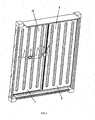
FIG. 1 is a schematic view showing structural details near door panels of an embodiment of a refrigerated container, with a security device installed at inner sides of the door panels; -
FIG. 2 shows an embodiment in which an antenna of the security device is installed outside the door panels; -
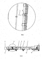
FIG. 3 is a cross-sectional view illustrating the security device installed on the door panels; -
FIG. 4 is an enlarged view of part A inFIG. 3 , showing a first embodiment of the displacement sensor; -
FIG. 5 is an enlarged view of part A inFIG. 3 , showing a second embodiment of the displacement sensor; -
FIG. 6 is an enlarged view of part A inFIG. 3 , showing a third embodiment of the displacement sensor; -
FIG. 7 shows a fourth embodiment of the displacement sensor; -
FIG. 8 is a side view showing the U-shaped member used in the fourth embodiment of the displacement sensor, and -
FIG. 9 shows a circuit diagram represented by the two reed switches in the fourth embodiment of the displacement sensor. - In the various figures, like reference signs show like parts.
- As shown in
FIGS. 1 ,2 and 3 , a refrigerated container includes a security device comprising adetection plate 5, twodoor panels monitoring module 2, a displacement sensor 4 and anantenna 8. Thedetection plate 5 has one end fixed to an inner side structure, e.g.inner lining 6 of thedoor panel 9, and the other opposite end as a free end extending towards thedoor panel 10 so that the free end of thedetection plate 5 will be positioned behind an inner side structure of thedoor panel 10 when the door is normally closed. The displacement sensor 4 is fixed to the inner side structure of thedoor panel 10 and approximates the free end of thedetection plate 5 so as to cooperate with the free end of thedetection plate 5 and to thus detect a relative displacement between the two door panels. Themonitoring module 2 is arranged within a heat insulating layer in thedoor panel 10, and is electrically connected to the displacement sensor 4 to receive and process outputs from the displacement sensor 4. Theantenna 8 is disposed within an anti-collision block on an outer side of thedoor panel 10 and near a pivot hinge of thedoor panel 10, and is electrically connected to themonitoring module 2 to receive and emit outputs from themonitoring module 2. Themonitoring module 2, the displacement sensor 4 and theantenna 8 are three components separately arranged in different locations of the container door. Particularly, in case of arranging in the same door panel, the displacement sensor, monitoring module and antenna are connected with each other by means of electrical wires or cables embedded into the heat insulating layer of the same door panel. - The inner side structures of the door panels may usually comprise inner linings. However, the inner side structures may further comprise a heat insulating structure connected to the inner side structure of the outside board of the door panel and exposing the inner lining of the door panel.
- In another embodiment, the
detection plate 5 may be fixed to thedoor panel 10, and accordingly the displacement sensor 4 is fixed to thedoor panel 9. In general, themonitoring module 2 and theantenna 8 are arranged on the same door panel as the displacement sensor 4. However, by arranging themonitoring module 2 and theantenna 8 on the same door panel as thedetection plate 5 and ensuring an electrical connection of themonitoring module 2 to the displacement sensor 4 as well as theantenna 8, an improvement over the prior art can also be accomplished. - In addition, the
antenna 8 may be arranged at other suitable portions of the outer side of the door panel, for example, in the vicinity of the locking handle, etc. - For enhancing the strength of a portion of the
inner lining 6 where thedetection plate 5 is connected, there is provided a reinforcer 61 (seeFIG. 4 ) of heat-insulating materials within thedoor panel 9. One end of thereinforcer 61 is fixed to anotherreinforcer 62 for reinforcing the strength of a part of the outer side of thedoor panel 9 where the locking handle is connected, and the other opposite end thereof just abuts against theinner lining 6. Thedetection plate 5 is fixed to the other opposite end of thereinforcer 61 of heat-insulating materials by means of screws. - The displacement sensor 4 may be embodied as suitable proximity switches, for example, a travel switch, a Hall switch, a reed switch, and the like, which will be described in detail hereinafter.
- As shown in
FIG. 4 , in this embodiment, the displacement sensor is implemented as atravel switch 101 fixed to theinner lining 7 of thedoor panel 10. Essential portions of thetravel switch 101 are disposed within a foamed heat insulating layer in thedoor panel 10. Further, a contact pin of thetravel switch 101 protrudes out of theinner lining 7 of thedoor panel 10. In the event that the door is completely closed, the aforementioned free end of thedetection plate 5 presses against the contact pin of thetravel switch 101 and thus thetravel switch 101 has a predetermined state, e.g. "ON" or "OFF". Once the free end of thedetection plate 5 releases engagement with the contact pin of thetravel switch 101, the state of thetravel switch 101 will be switched, for example, from "OFF" to "ON" (a normally open type) or vice versa (a normally closed type), and at the same time a signal indicating that the door is closed or opened is transmitted to themonitoring module 2. Accordingly, once occurrence of unauthorized opening of the door, thetravel switch 101 will transmit signals to themonitoring module 2 indicating that the door is unauthorizedly opened. - As shown in
FIG. 5 , in this embodiment, the displacement sensor is implemented as aHall sensor 102 fixed to an outer surface of theinner lining 7 of thedoor panel 10. Amagnetic member 103 such as magnet, magnetic rubber, etc. is disposed on a portion of thedetection plate 5 facing theHall sensor 102 by glue or screws. - Instead of disposing the magnetic member on the
detection plate 5, thedetection plate 5 or at least the portion of thedetection plate 5 facing theHall sensor 102 may be formed of magnetic conductive materials or magnetic materials. - When the
magnetic member 103 or the magnetic conductive materials of thedetection plate 5 approaches or moves away from theHall sensor 102, state of theHall sensor 102 will vary, for example, from "OFF" to "ON" (a normally open type) or from "ON" to "OFF" (a normally closed type), and in turn a signal indicating the door is closed or opened is transmitted to themonitoring module 2. Upon occurrence of unauthorized opening of the door, theHall sensor 102 will transmit respective signals to themonitoring module 2 indicating unauthorized opening of the door. - As shown in
FIG. 6 , in this embodiment, the displacement sensor is implemented as areed switch 105. In addition, the inner side structure of thedoor panel 10 comprises aU-shaped member 104 fixed to theinner lining 7 of thedoor panel 10. Thereed switch 105 is mounted to one of two opposite side walls of theU-shaped member 104, and amagnetic member 106 such as magnet, magnetic rubber or the like is mounted to the other of the two opposite side walls of theU-shaped member 104. Here, the free end of thedetection plate 5 is formed with a bent portion which may be inserted into a gap between the two opposite side walls of theU-shaped member 104 when the door is closed, so as to prevent magnetic lines of themagnetic member 106 from being reached thereed switch 105. Thereed switch 105 may be a normally closed type or a normally open type, depending on the specific requirement for an internal arrangement of themonitoring module 2. - Instead of the
reed switch 105, other proximity switches like capacitive proximity switches, inductive proximity switches may be used. - The
U-shaped member 104 is preferably made of non-magnetic materials such as plastic materials so as to avoid affecting magnetic lines of themagnetic member 106. Themagnetic member 106 and thereed switch 105 may be disposed within the two opposite side walls of theU-shaped member 104, and alternatively may be attached to inner surfaces or outer surfaces of the two side walls of theU-shaped member 104. Particularly, when theU-shaped member 104 is made of metal materials, themagnetic member 106 and thereed switch 105 are preferably to be respectively attached to inner surfaces of the two side walls of theU-shaped member 104. - When the bent portion of the free end of the
detection plate 5 is inserted into the gap between themagnetic member 106 and thereed switch 105 and thus prevents a majority of magnetic lines of themagnetic member 106 from being reached thereed switch 105, or reversely the bent portion of the free end of thedetection plate 5 retreats from the gap between themagnetic member 106 and thereed switch 105, the state of thereed switch 105 will be switched from "OFF" to "ON" (a normally open type), or from "ON" to "OFF" (a normally closed type), and a signal indicating the door is opened or closed is transmitted to themonitoring module 2. Accordingly, once occurrence of unauthorized opening of the door, thereed switch 105 will transmit respective signals to themonitoring module 2 indicating unauthorized opening of the door. - As shown in
FIGS. 6 and 8 , the structure of this embodiment is substantially the same as that of the third embodiment, except that tworeed switches reed switches inner lining 7 of thedoor panel 10, and are spaced apart from each other so that the bent portion of the free end of thedetection plate 5 may in steps shield the magnetic lines of themagnetic member 106 from reaching the reed switches 107 and 108. As for the two reed switches, thereed switch 107 which is located adjacent to the opening of the U-shaped member is a normally open type, and thereed switch 108 which is located away from the opening of the U-shaped member is a normally closed type. - As shown in
FIGS. 7 and 9 , before the bent portion of the free end of thedetection plate 5 is inserted between themagnetic materials 106 and thereed switch 107, thereed switch 107 is in an "OFF" state and thereed switch 108 is in an "ON" state so that the circuit involving the reed switches 107 and 108 are powered off. When the bent portion of the free end of thedetection plate 5 is inserted between themagnetic materials 106 and thereed switch 107, the state of thereed switch 107 changes from "OFF" to "ON", and thus the circuit involving the reed switches 107 and 108 is powered on and simultaneously a signal indicating the status of the door is transmitted to themonitoring module 2. As the bent portion of the free end of thedetection plate 5 is further inserted between themagnetic material 106 and thereed switch 108, the state of thereed switch 108 changes from "ON" to "OFF", and thus the circuit involving the reed switches 107 and 108 is again powered off. The varying processes of the reed switches 107 and 108 when the bent portion of thedetection plate 5 retreats from the gap between the two opposite side walls of the U-shaped member are just contrary to those when the bent portion of thedetection plate 5 inserts into the gap. Thus, upon occurrence of unauthorized opening of door, a corresponding signal may be transmitted to themonitoring module 2. The present embodiment is advantageous in that power consumption of the security device may be reduced.
Claims (10)
- A refrigerated container, comprising a security device and a door composed of a first door panel (9) and a second door panel (10), said security device including:a detection plate (5) having a first end fixed to an inner side structure of the first door panel, and a second opposite end as a free end extending towards the second door panel (10) and being positioned behind an inner side structure of the second door panel (10) when the door is closed;a displacement sensor (4) fixed to the inner side structure of the second door panel (10) and positioned adjacent to the free end of the detection plate (5) so as to cooperate with the free end of the detection plate (5) and to thus detect a relative displacement between the two door panels (9,10);a monitoring module (2) electrically connected to the displacement sensor (4) to receive and process outputs from the displacement sensor (4); andan antenna (8) electrically connected to the monitoring module (2) to receive and emit outputs from the monitoring module (2);characterised in that said displacement sensor (4), monitoring module (2) and antenna (8) are separately arranged in the door, and said monitoring module (2) is arranged within a heat insulting layer in the first door panel (9) or the second door panel (10) and said antenna (8) is provided at an outer side of the first door panel (9) or the second door panel (10).
- A refrigerated container according to claim 1, wherein in case of arranging on a single door panel (9,10) said displacement sensor (4), monitoring module (2) and antenna (8) are connected with each other by means of electrical wires or cables embedded into said heat insulating layer of the door panel (9,10).
- A refrigerated container according to claim 1, wherein said displacement sensor (4) is a travel switch (101), said inner side structure of the second door panel (10) comprises an inner lining (7) and the travel switch (101) is fixed to the inner lining; and
a contact pin of the travel switch (101) protrudes out of the inner lining (7), and said free end of the detection plate (5) is configured to press against the contact pin of the travel switch (101) when the door is closed and release the contact pin of the travel switch (101) when the door is opened so as to switch states of the travel switch (101). - A refrigerated container according to claim 1, wherein said displacement sensor (4) is a Hall sensor (102) said inner side structure of the second door panel (10) comprises an inner lining, and the Hall sensor (102) is fixed to the inner lining (7); and
said free end of the detection plate (5) includes magnetic conductive materials configured to face the Hall sensor (102) when the door is closed. - A refrigerated container according to claim 1, wherein said displacement sensor (4) is a Hall sensor (102), said inner side structure of the second door panel (10) comprises an inner lining, and the Hall sensor (102) is fixed to the inner lining; and
said free end of the detection plate (5) includes a magnetic member (103), and said magnetic member (103) is fixed to a portion of said detection plate (5) which faces the Hall sensor (102) when the door is closed. - A refrigerated container according to claim 1, wherein said displacement sensor (4) is a proximity switch, and said inner side structure of the second door panel (10) comprises an inner lining (7) and a U-shaped member (104) fixed to the inner lining; and
the proximity switch is fixed to one of two opposite side walls of the U-shaped member (104) and a magnetic member (106) opposite to the proximity switch is fixed to the other one of the two opposite side walls of the U-shaped member (104); and
said free end of the detection plate (5) includes a bent portion which is inserted into a gap between the two opposite side walls of the U-shaped member (104) and prevents magnetic lines of the magnetic member (106) from reaching the proximity switch when the door is closed. - A refrigerated container according to claim 6, wherein said proximity switch is one of a normally closed type and a normally open type of reed switch (105).
- A refrigerated container according to claim 6, wherein said proximity switch includes two reed switches (107,108) electrically connected in series and arranged to be substantially in parallel with the inner lining (7) and to be spaced apart from each other; and
one of said two reed switches (107,108) near an opening of said U-shaped member (104) is a normally open type, the other one away from the opening of said U-shaped member (104) is a normally closed type. - A refrigerated container according to any preceding claim, further comprising a reinforcer (61) of heat-insulating materials arranged within the first door panel (9) and abutting against an inner lining (6) of the first door pannel (9), said detection plate (5) being fixed to the reinforcer (61) of heat-insulatin materials.
- A refrigerated container according to any preceding claim, wherein said antenna (8) is arranged within an anti-collision block mounted on a pivot hinge of the first door panel (9) or the second door panel (10).
Applications Claiming Priority (1)
| Application Number | Priority Date | Filing Date | Title |
|---|---|---|---|
| CN200610033102A CN101003323B (en) | 2006-01-16 | 2006-01-16 | Smart refrigerated container |
Publications (3)
| Publication Number | Publication Date |
|---|---|
| EP1850079A2 EP1850079A2 (en) | 2007-10-31 |
| EP1850079A3 EP1850079A3 (en) | 2008-04-02 |
| EP1850079B1 true EP1850079B1 (en) | 2009-06-10 |
Family
ID=38346049
Family Applications (1)
| Application Number | Title | Priority Date | Filing Date |
|---|---|---|---|
| EP20070250135 Not-in-force EP1850079B1 (en) | 2006-01-16 | 2007-01-15 | Refrigerated container |
Country Status (7)
| Country | Link |
|---|---|
| US (1) | US7612664B2 (en) |
| EP (1) | EP1850079B1 (en) |
| CN (1) | CN101003323B (en) |
| AT (1) | ATE433558T1 (en) |
| AU (1) | AU2007200168A1 (en) |
| BR (1) | BRPI0700047A (en) |
| DE (1) | DE602007001261D1 (en) |
Families Citing this family (21)
| Publication number | Priority date | Publication date | Assignee | Title |
|---|---|---|---|---|
| US7663483B2 (en) * | 2006-12-16 | 2010-02-16 | Roc2Loc, Inc. | Methods and apparatus for security device portal sensing |
| US7598862B2 (en) * | 2006-12-16 | 2009-10-06 | Roc2Loc, Inc. | Methods and apparatus for security device coupling |
| US20100085149A1 (en) * | 2006-12-16 | 2010-04-08 | Roc2Loc Inc. | Systems and Methods for Mounting a Security Device |
| US7667600B2 (en) * | 2006-12-16 | 2010-02-23 | Roc2Loc, Inc. | Methods and apparatus for security device removal detection |
| WO2009146019A2 (en) * | 2008-04-01 | 2009-12-03 | Quixcode Llc | Methods and apparatus for security device portal sensing |
| US7889079B2 (en) * | 2008-06-07 | 2011-02-15 | Kuwait University | Anti security system for manhole covers |
| US8959036B2 (en) * | 2010-03-10 | 2015-02-17 | Apl Limited | Real time monitoring of ship cargo |
| US20120112910A1 (en) * | 2010-11-08 | 2012-05-10 | System Planning Corporation, Inc. | Cargo Container Self-Arming Monitoring And Security Device |
| US9310279B2 (en) * | 2012-12-07 | 2016-04-12 | Thermo King Corporation | System for tracking and testing generator sets used in conjunction with temperature controlled containers |
| CN105987562B (en) * | 2015-02-13 | 2020-05-05 | 博西华家用电器有限公司 | Refrigeration appliance |
| SG11201802903SA (en) * | 2015-10-22 | 2018-05-30 | Carrier Corp | Modular cold boxes for transport refrigeration unit |
| JP6754983B2 (en) * | 2016-09-05 | 2020-09-16 | パナソニックIpマネジメント株式会社 | Cold storage |
| EP3526528B1 (en) | 2016-10-12 | 2022-03-02 | Carrier Corporation | A container ship or container yard, and method of operating refrigerated storage containers provided thereon |
| CN108253683B (en) * | 2018-01-16 | 2024-03-29 | 广东英得尔实业发展有限公司 | Vehicle-mounted refrigerator |
| CN110937257A (en) * | 2018-09-21 | 2020-03-31 | 南通中集特种运输设备制造有限公司 | A container door assembly and a container including the same |
| GR1009881B (en) | 2020-02-11 | 2020-12-02 | People Technology Solutions, Ltd. | Door for smart shipping containers |
| FR3108106B1 (en) * | 2020-03-10 | 2022-04-29 | People Tech Solutions Ltd | Smart Shipping Container Door |
| US20240302091A1 (en) * | 2021-02-03 | 2024-09-12 | Peli Biothermal Llc | Passive thermally controlled condition-in-place shipping container |
| CN115565352A (en) * | 2022-01-06 | 2023-01-03 | 云成达(杭州)科技有限公司 | Amine liquid absorption tower and regeneration tower foaming fault prediction early warning system |
| USD1095021S1 (en) * | 2024-06-04 | 2025-09-30 | Shanghai Shifu Industrial Development Co., Ltd | Shipping container door |
| USD1084419S1 (en) * | 2024-06-04 | 2025-07-15 | Shanghai Shifu Industrial Development Co., Ltd | Shipping container door |
Family Cites Families (11)
| Publication number | Priority date | Publication date | Assignee | Title |
|---|---|---|---|---|
| GB2013332A (en) * | 1978-01-28 | 1979-08-08 | Plessey Co Ltd | Improvements in or relating to optical detecting arrangements |
| AU7597996A (en) * | 1995-10-30 | 1997-05-22 | Mi-Jack Products Inc. | Security system for cargo loading doors |
| IL126008A (en) * | 1998-08-31 | 2003-10-31 | Hi G Tek | Electronic monitoring apparatus |
| GB0110759D0 (en) * | 2001-05-02 | 2001-06-27 | Marks Roger J | Antenna clamp |
| US6879257B2 (en) * | 2002-02-25 | 2005-04-12 | Omron Corporation | State surveillance system and method for an object and the adjacent space, and a surveillance system for freight containers |
| US20040055345A1 (en) * | 2002-09-24 | 2004-03-25 | Moore Gregory B. | Door lock system for trailers and cargo containers |
| US7242296B2 (en) * | 2003-09-18 | 2007-07-10 | China International Marine Containers (Group) Co., Ltd. | Safe intelligent container |
| CN1623866B (en) * | 2003-09-18 | 2010-04-21 | 中国国际海运集装箱(集团)股份有限公司 | Safe Smart Container |
| CN2690346Y (en) * | 2003-10-27 | 2005-04-06 | 中国国际海运集装箱(集团)股份有限公司 | Hidden container safety device and container |
| KR101124961B1 (en) * | 2003-11-13 | 2012-03-27 | 커머스가드 에이비 | Method and System For Monitoring Containers To Maintain the Security Thereof |
| CN2871434Y (en) * | 2006-01-16 | 2007-02-21 | 中国国际海运集装箱(集团)股份有限公司 | Intelligent freezing container |
-
2006
- 2006-01-16 CN CN200610033102A patent/CN101003323B/en not_active Expired - Fee Related
-
2007
- 2007-01-15 EP EP20070250135 patent/EP1850079B1/en not_active Not-in-force
- 2007-01-15 DE DE200760001261 patent/DE602007001261D1/en active Active
- 2007-01-15 US US11/623,152 patent/US7612664B2/en not_active Expired - Fee Related
- 2007-01-15 AT AT07250135T patent/ATE433558T1/en not_active IP Right Cessation
- 2007-01-16 AU AU2007200168A patent/AU2007200168A1/en not_active Abandoned
- 2007-01-16 BR BRPI0700047-2A patent/BRPI0700047A/en not_active IP Right Cessation
Also Published As
| Publication number | Publication date |
|---|---|
| US7612664B2 (en) | 2009-11-03 |
| EP1850079A2 (en) | 2007-10-31 |
| ATE433558T1 (en) | 2009-06-15 |
| EP1850079A3 (en) | 2008-04-02 |
| BRPI0700047A (en) | 2007-11-06 |
| CN101003323B (en) | 2010-05-12 |
| CN101003323A (en) | 2007-07-25 |
| AU2007200168A1 (en) | 2007-08-02 |
| DE602007001261D1 (en) | 2009-07-23 |
| US20070193319A1 (en) | 2007-08-23 |
Similar Documents
| Publication | Publication Date | Title |
|---|---|---|
| US7612664B2 (en) | Refrigerated container | |
| EP3053152B1 (en) | Slim wireless window opening detector | |
| US7436298B2 (en) | Container security and monitoring | |
| US20100327999A1 (en) | Security switch assemblies for shipping containers and the like | |
| EP3094797B1 (en) | A key box | |
| US6737969B2 (en) | Wireless security sensor systems for windows and doors | |
| US7388467B2 (en) | System and method for determining a state of a door | |
| US12033448B2 (en) | Keyless puck lock apparatus and system | |
| US8314698B2 (en) | Anti-tamper assembly for surface mounted security switch | |
| US10422168B2 (en) | Energy-saving magnetic lock | |
| EP0189147A1 (en) | Padlock with tamper-actuated audible and/or inaudible alarm | |
| US11739560B1 (en) | System and apparatus for sensing and providing alerts for deadbolt lock status | |
| US7154394B2 (en) | Hidden security device and container using the same | |
| JP3239764U (en) | Vehicle equipment sealing device | |
| TW201704609A (en) | Lock with integrated lock sensor | |
| US20210304534A1 (en) | Keyless puck lock apparatus and system | |
| EP3339109B1 (en) | Locking assembly | |
| US20040100254A1 (en) | Detector arrangement | |
| KR100749638B1 (en) | Deadbolt type electromagnet door lock | |
| KR101498256B1 (en) | Complex key structure for controlling doorlock | |
| CN2916077Y (en) | Theftproof door with lockhole anti-prying remotely-controlled device | |
| WO1998049702A1 (en) | Magnetic proximity switch system with slide-by anti-defeat mechanism | |
| CN121611349A (en) | Lockset and electronic key management method | |
| ITMI20061585A1 (en) | ANTITHEFT FOR MOTOR VEHICLES | |
| BRMU8700951U2 (en) | Constructive arrangement introduced in remote control electromagnetic safety lock for cargo transport vehicles |
Legal Events
| Date | Code | Title | Description |
|---|---|---|---|
| PUAI | Public reference made under article 153(3) epc to a published international application that has entered the european phase |
Free format text: ORIGINAL CODE: 0009012 |
|
| AK | Designated contracting states |
Kind code of ref document: A2 Designated state(s): AT BE BG CH CY CZ DE DK EE ES FI FR GB GR HU IE IS IT LI LT LU LV MC NL PL PT RO SE SI SK TR |
|
| AX | Request for extension of the european patent |
Extension state: AL BA HR MK YU |
|
| PUAL | Search report despatched |
Free format text: ORIGINAL CODE: 0009013 |
|
| AK | Designated contracting states |
Kind code of ref document: A3 Designated state(s): AT BE BG CH CY CZ DE DK EE ES FI FR GB GR HU IE IS IT LI LT LU LV MC NL PL PT RO SE SI SK TR |
|
| AX | Request for extension of the european patent |
Extension state: AL BA HR MK YU |
|
| 17P | Request for examination filed |
Effective date: 20080710 |
|
| GRAP | Despatch of communication of intention to grant a patent |
Free format text: ORIGINAL CODE: EPIDOSNIGR1 |
|
| AKX | Designation fees paid |
Designated state(s): AT BE BG CH CY CZ DE DK EE ES FI FR GB GR HU IE IS IT LI LT LU LV MC NL PL PT RO SE SI SK TR |
|
| GRAS | Grant fee paid |
Free format text: ORIGINAL CODE: EPIDOSNIGR3 |
|
| GRAA | (expected) grant |
Free format text: ORIGINAL CODE: 0009210 |
|
| AK | Designated contracting states |
Kind code of ref document: B1 Designated state(s): AT BE BG CH CY CZ DE DK EE ES FI FR GB GR HU IE IS IT LI LT LU LV MC NL PL PT RO SE SI SK TR |
|
| REG | Reference to a national code |
Ref country code: GB Ref legal event code: FG4D |
|
| REG | Reference to a national code |
Ref country code: CH Ref legal event code: EP |
|
| REG | Reference to a national code |
Ref country code: IE Ref legal event code: FG4D |
|
| REF | Corresponds to: |
Ref document number: 602007001261 Country of ref document: DE Date of ref document: 20090723 Kind code of ref document: P |
|
| PG25 | Lapsed in a contracting state [announced via postgrant information from national office to epo] |
Ref country code: LT Free format text: LAPSE BECAUSE OF FAILURE TO SUBMIT A TRANSLATION OF THE DESCRIPTION OR TO PAY THE FEE WITHIN THE PRESCRIBED TIME-LIMIT Effective date: 20090610 Ref country code: AT Free format text: LAPSE BECAUSE OF FAILURE TO SUBMIT A TRANSLATION OF THE DESCRIPTION OR TO PAY THE FEE WITHIN THE PRESCRIBED TIME-LIMIT Effective date: 20090610 Ref country code: FI Free format text: LAPSE BECAUSE OF FAILURE TO SUBMIT A TRANSLATION OF THE DESCRIPTION OR TO PAY THE FEE WITHIN THE PRESCRIBED TIME-LIMIT Effective date: 20090610 |
|
| NLV1 | Nl: lapsed or annulled due to failure to fulfill the requirements of art. 29p and 29m of the patents act | ||
| PG25 | Lapsed in a contracting state [announced via postgrant information from national office to epo] |
Ref country code: SE Free format text: LAPSE BECAUSE OF FAILURE TO SUBMIT A TRANSLATION OF THE DESCRIPTION OR TO PAY THE FEE WITHIN THE PRESCRIBED TIME-LIMIT Effective date: 20090910 Ref country code: SI Free format text: LAPSE BECAUSE OF FAILURE TO SUBMIT A TRANSLATION OF THE DESCRIPTION OR TO PAY THE FEE WITHIN THE PRESCRIBED TIME-LIMIT Effective date: 20090610 Ref country code: LV Free format text: LAPSE BECAUSE OF FAILURE TO SUBMIT A TRANSLATION OF THE DESCRIPTION OR TO PAY THE FEE WITHIN THE PRESCRIBED TIME-LIMIT Effective date: 20090610 Ref country code: NL Free format text: LAPSE BECAUSE OF FAILURE TO SUBMIT A TRANSLATION OF THE DESCRIPTION OR TO PAY THE FEE WITHIN THE PRESCRIBED TIME-LIMIT Effective date: 20090610 Ref country code: PL Free format text: LAPSE BECAUSE OF FAILURE TO SUBMIT A TRANSLATION OF THE DESCRIPTION OR TO PAY THE FEE WITHIN THE PRESCRIBED TIME-LIMIT Effective date: 20090610 |
|
| PG25 | Lapsed in a contracting state [announced via postgrant information from national office to epo] |
Ref country code: IS Free format text: LAPSE BECAUSE OF FAILURE TO SUBMIT A TRANSLATION OF THE DESCRIPTION OR TO PAY THE FEE WITHIN THE PRESCRIBED TIME-LIMIT Effective date: 20091010 Ref country code: ES Free format text: LAPSE BECAUSE OF FAILURE TO SUBMIT A TRANSLATION OF THE DESCRIPTION OR TO PAY THE FEE WITHIN THE PRESCRIBED TIME-LIMIT Effective date: 20090921 Ref country code: CZ Free format text: LAPSE BECAUSE OF FAILURE TO SUBMIT A TRANSLATION OF THE DESCRIPTION OR TO PAY THE FEE WITHIN THE PRESCRIBED TIME-LIMIT Effective date: 20090610 Ref country code: EE Free format text: LAPSE BECAUSE OF FAILURE TO SUBMIT A TRANSLATION OF THE DESCRIPTION OR TO PAY THE FEE WITHIN THE PRESCRIBED TIME-LIMIT Effective date: 20090610 Ref country code: RO Free format text: LAPSE BECAUSE OF FAILURE TO SUBMIT A TRANSLATION OF THE DESCRIPTION OR TO PAY THE FEE WITHIN THE PRESCRIBED TIME-LIMIT Effective date: 20090610 |
|
| PG25 | Lapsed in a contracting state [announced via postgrant information from national office to epo] |
Ref country code: BE Free format text: LAPSE BECAUSE OF FAILURE TO SUBMIT A TRANSLATION OF THE DESCRIPTION OR TO PAY THE FEE WITHIN THE PRESCRIBED TIME-LIMIT Effective date: 20090610 Ref country code: SK Free format text: LAPSE BECAUSE OF FAILURE TO SUBMIT A TRANSLATION OF THE DESCRIPTION OR TO PAY THE FEE WITHIN THE PRESCRIBED TIME-LIMIT Effective date: 20090610 |
|
| PG25 | Lapsed in a contracting state [announced via postgrant information from national office to epo] |
Ref country code: BG Free format text: LAPSE BECAUSE OF FAILURE TO SUBMIT A TRANSLATION OF THE DESCRIPTION OR TO PAY THE FEE WITHIN THE PRESCRIBED TIME-LIMIT Effective date: 20090910 Ref country code: PT Free format text: LAPSE BECAUSE OF FAILURE TO SUBMIT A TRANSLATION OF THE DESCRIPTION OR TO PAY THE FEE WITHIN THE PRESCRIBED TIME-LIMIT Effective date: 20091010 |
|
| PLBE | No opposition filed within time limit |
Free format text: ORIGINAL CODE: 0009261 |
|
| STAA | Information on the status of an ep patent application or granted ep patent |
Free format text: STATUS: NO OPPOSITION FILED WITHIN TIME LIMIT |
|
| PG25 | Lapsed in a contracting state [announced via postgrant information from national office to epo] |
Ref country code: DK Free format text: LAPSE BECAUSE OF FAILURE TO SUBMIT A TRANSLATION OF THE DESCRIPTION OR TO PAY THE FEE WITHIN THE PRESCRIBED TIME-LIMIT Effective date: 20090610 |
|
| 26N | No opposition filed |
Effective date: 20100311 |
|
| PG25 | Lapsed in a contracting state [announced via postgrant information from national office to epo] |
Ref country code: MC Free format text: LAPSE BECAUSE OF NON-PAYMENT OF DUE FEES Effective date: 20100131 |
|
| PG25 | Lapsed in a contracting state [announced via postgrant information from national office to epo] |
Ref country code: GR Free format text: LAPSE BECAUSE OF FAILURE TO SUBMIT A TRANSLATION OF THE DESCRIPTION OR TO PAY THE FEE WITHIN THE PRESCRIBED TIME-LIMIT Effective date: 20090911 |
|
| PG25 | Lapsed in a contracting state [announced via postgrant information from national office to epo] |
Ref country code: IE Free format text: LAPSE BECAUSE OF NON-PAYMENT OF DUE FEES Effective date: 20100115 |
|
| PG25 | Lapsed in a contracting state [announced via postgrant information from national office to epo] |
Ref country code: IT Free format text: LAPSE BECAUSE OF FAILURE TO SUBMIT A TRANSLATION OF THE DESCRIPTION OR TO PAY THE FEE WITHIN THE PRESCRIBED TIME-LIMIT Effective date: 20090610 |
|
| REG | Reference to a national code |
Ref country code: CH Ref legal event code: PL |
|
| PG25 | Lapsed in a contracting state [announced via postgrant information from national office to epo] |
Ref country code: LI Free format text: LAPSE BECAUSE OF NON-PAYMENT OF DUE FEES Effective date: 20110131 Ref country code: CH Free format text: LAPSE BECAUSE OF NON-PAYMENT OF DUE FEES Effective date: 20110131 |
|
| PG25 | Lapsed in a contracting state [announced via postgrant information from national office to epo] |
Ref country code: CY Free format text: LAPSE BECAUSE OF FAILURE TO SUBMIT A TRANSLATION OF THE DESCRIPTION OR TO PAY THE FEE WITHIN THE PRESCRIBED TIME-LIMIT Effective date: 20090610 |
|
| PG25 | Lapsed in a contracting state [announced via postgrant information from national office to epo] |
Ref country code: LU Free format text: LAPSE BECAUSE OF NON-PAYMENT OF DUE FEES Effective date: 20100115 Ref country code: HU Free format text: LAPSE BECAUSE OF FAILURE TO SUBMIT A TRANSLATION OF THE DESCRIPTION OR TO PAY THE FEE WITHIN THE PRESCRIBED TIME-LIMIT Effective date: 20091211 |
|
| PG25 | Lapsed in a contracting state [announced via postgrant information from national office to epo] |
Ref country code: TR Free format text: LAPSE BECAUSE OF FAILURE TO SUBMIT A TRANSLATION OF THE DESCRIPTION OR TO PAY THE FEE WITHIN THE PRESCRIBED TIME-LIMIT Effective date: 20090610 |
|
| REG | Reference to a national code |
Ref country code: FR Ref legal event code: PLFP Year of fee payment: 9 |
|
| PGFP | Annual fee paid to national office [announced via postgrant information from national office to epo] |
Ref country code: DE Payment date: 20150106 Year of fee payment: 9 |
|
| PGFP | Annual fee paid to national office [announced via postgrant information from national office to epo] |
Ref country code: GB Payment date: 20150114 Year of fee payment: 9 Ref country code: FR Payment date: 20150108 Year of fee payment: 9 |
|
| REG | Reference to a national code |
Ref country code: DE Ref legal event code: R119 Ref document number: 602007001261 Country of ref document: DE |
|
| GBPC | Gb: european patent ceased through non-payment of renewal fee |
Effective date: 20160115 |
|
| REG | Reference to a national code |
Ref country code: FR Ref legal event code: ST Effective date: 20160930 |
|
| PG25 | Lapsed in a contracting state [announced via postgrant information from national office to epo] |
Ref country code: DE Free format text: LAPSE BECAUSE OF NON-PAYMENT OF DUE FEES Effective date: 20160802 Ref country code: GB Free format text: LAPSE BECAUSE OF NON-PAYMENT OF DUE FEES Effective date: 20160115 |
|
| PG25 | Lapsed in a contracting state [announced via postgrant information from national office to epo] |
Ref country code: FR Free format text: LAPSE BECAUSE OF NON-PAYMENT OF DUE FEES Effective date: 20160201 |