EP1850036A1 - Transmission Structure of Power Unit for Vehicle - Google Patents
Transmission Structure of Power Unit for Vehicle Download PDFInfo
- Publication number
- EP1850036A1 EP1850036A1 EP07104612A EP07104612A EP1850036A1 EP 1850036 A1 EP1850036 A1 EP 1850036A1 EP 07104612 A EP07104612 A EP 07104612A EP 07104612 A EP07104612 A EP 07104612A EP 1850036 A1 EP1850036 A1 EP 1850036A1
- Authority
- EP
- European Patent Office
- Prior art keywords
- oil
- continuously variable
- variable transmission
- hydrostatic continuously
- neutral
- Prior art date
- Legal status (The legal status is an assumption and is not a legal conclusion. Google has not performed a legal analysis and makes no representation as to the accuracy of the status listed.)
- Granted
Links
- 230000005540 biological transmission Effects 0.000 title claims abstract description 119
- 230000002706 hydrostatic effect Effects 0.000 claims abstract description 47
- 230000007935 neutral effect Effects 0.000 claims abstract description 32
- 238000002485 combustion reaction Methods 0.000 claims abstract description 16
- 238000011144 upstream manufacturing Methods 0.000 claims abstract description 5
- 239000003921 oil Substances 0.000 description 190
- 238000010586 diagram Methods 0.000 description 4
- 229910000831 Steel Inorganic materials 0.000 description 2
- 239000002828 fuel tank Substances 0.000 description 2
- 239000010687 lubricating oil Substances 0.000 description 2
- 239000010959 steel Substances 0.000 description 2
- 239000010724 circulating oil Substances 0.000 description 1
- 238000001816 cooling Methods 0.000 description 1
- 239000000498 cooling water Substances 0.000 description 1
- 230000000694 effects Effects 0.000 description 1
- 239000000945 filler Substances 0.000 description 1
- 230000001050 lubricating effect Effects 0.000 description 1
Images





Classifications
-
- F—MECHANICAL ENGINEERING; LIGHTING; HEATING; WEAPONS; BLASTING
- F16—ENGINEERING ELEMENTS AND UNITS; GENERAL MEASURES FOR PRODUCING AND MAINTAINING EFFECTIVE FUNCTIONING OF MACHINES OR INSTALLATIONS; THERMAL INSULATION IN GENERAL
- F16H—GEARING
- F16H47/00—Combinations of mechanical gearing with fluid clutches or fluid gearing
- F16H47/02—Combinations of mechanical gearing with fluid clutches or fluid gearing the fluid gearing being of the volumetric type
-
- F—MECHANICAL ENGINEERING; LIGHTING; HEATING; WEAPONS; BLASTING
- F16—ENGINEERING ELEMENTS AND UNITS; GENERAL MEASURES FOR PRODUCING AND MAINTAINING EFFECTIVE FUNCTIONING OF MACHINES OR INSTALLATIONS; THERMAL INSULATION IN GENERAL
- F16H—GEARING
- F16H57/00—General details of gearing
- F16H57/02—Gearboxes; Mounting gearing therein
- F16H2057/02039—Gearboxes for particular applications
- F16H2057/02043—Gearboxes for particular applications for vehicle transmissions
- F16H2057/02065—Gearboxes for particular applications for vehicle transmissions for motorcycles or squads
-
- F—MECHANICAL ENGINEERING; LIGHTING; HEATING; WEAPONS; BLASTING
- F16—ENGINEERING ELEMENTS AND UNITS; GENERAL MEASURES FOR PRODUCING AND MAINTAINING EFFECTIVE FUNCTIONING OF MACHINES OR INSTALLATIONS; THERMAL INSULATION IN GENERAL
- F16H—GEARING
- F16H39/00—Rotary fluid gearing using pumps and motors of the volumetric type, i.e. passing a predetermined volume of fluid per revolution
- F16H39/04—Rotary fluid gearing using pumps and motors of the volumetric type, i.e. passing a predetermined volume of fluid per revolution with liquid motor and pump combined in one unit
- F16H39/06—Rotary fluid gearing using pumps and motors of the volumetric type, i.e. passing a predetermined volume of fluid per revolution with liquid motor and pump combined in one unit pump and motor being of the same type
- F16H39/08—Rotary fluid gearing using pumps and motors of the volumetric type, i.e. passing a predetermined volume of fluid per revolution with liquid motor and pump combined in one unit pump and motor being of the same type each with one main shaft and provided with pistons reciprocating in cylinders
- F16H39/10—Rotary fluid gearing using pumps and motors of the volumetric type, i.e. passing a predetermined volume of fluid per revolution with liquid motor and pump combined in one unit pump and motor being of the same type each with one main shaft and provided with pistons reciprocating in cylinders with cylinders arranged around, and parallel or approximately parallel to the main axis of the gearing
- F16H39/14—Rotary fluid gearing using pumps and motors of the volumetric type, i.e. passing a predetermined volume of fluid per revolution with liquid motor and pump combined in one unit pump and motor being of the same type each with one main shaft and provided with pistons reciprocating in cylinders with cylinders arranged around, and parallel or approximately parallel to the main axis of the gearing with cylinders carried in rotary cylinder blocks or cylinder-bearing members
-
- F—MECHANICAL ENGINEERING; LIGHTING; HEATING; WEAPONS; BLASTING
- F16—ENGINEERING ELEMENTS AND UNITS; GENERAL MEASURES FOR PRODUCING AND MAINTAINING EFFECTIVE FUNCTIONING OF MACHINES OR INSTALLATIONS; THERMAL INSULATION IN GENERAL
- F16H—GEARING
- F16H57/00—General details of gearing
- F16H57/04—Features relating to lubrication or cooling or heating
Definitions
- the present invention relates to the transmission structure of a power unit for a vehicle.
- Oil for operating and lubricating a hydrostatic continuously variable transmission is supplied from a central hole oil passage of a transmission shaft.
- oil for operating a neutral/drive switching clutch is supplied through an oil passage on the downstream side of the hydrostatic continuously variable transmission acquired by extending the central hole oil passage of the transmission shaft (for example, refer to a patent document 1).
- Patent document 1 JP-A No. 2001-140951 (Fig. 3)
- the present invention is made to address the problem, and the invention according to Claim 1 relates to transmission structure of a power unit for a vehicle having a characteristic that it is provided with an oil pump that is rotated by the driving force of an internal combustion engine and supplies oil to a hydrostatic continuously variable transmission and a neutral/drive switching clutch which is arranged between the hydrostatic continuously variable transmission and a rear wheel, in which a hydraulic piston adjacent of each set of driving friction plates and driven friction plates is moved by pressure in an oil pressure chamber and which connects and disconnects the driving force in the transmission structure of the power unit for the vehicle provided with the hydrostatic continuously variable transmission for shifting and transmitting the driving force from the internal combustion engine to the rear wheel and an oil passage to the neutral/drive switching clutch is branched from an oil passage from the oil pump to the upstream side of the hydrostatic continuously variable transmission.
- the invention according to Claim 2 has a characteristic that in the transmission structure of the power unit for the vehicle according to Claim 1, a lock-up actuator that fixes transmission gear ratio is provided to the hydrostatic continuously variable transmission and an oil passage to the lock-up actuator is branched from the oil passage to the neutral/drive switching clutch.
- the invention according to Claim 3 has a characteristic that in the transmission structure of the power unit for the vehicle according to Claim 1 or 2, the rotation axis of the hydrostatic continuously variable transmission and that of the neutral/drive switching clutch are parallel in the power unit for the vehicle and oil is supplied to both hydrostatic continuously variable transmission and the neutral/drive switching clutch via oil passages provided inside the same cover.
- the invention according to Claim 4 has a characteristic that in the transmission structure of the power unit for the vehicle according to Claim 3, the rotation axis of the hydrostatic continuously variable transmission and that of the neutral/drive switching clutch are parallel in the power unit for the vehicle and the rotation axis of the neutral/drive switching clutch is arranged on the upside of the rotation axis of the hydrostatic continuously variable transmission.
- the oil passage from the oil pump is used for both and can be simplified, and the oil passage can be miniaturized.
- the oil passages are provided inside the same cover, the oil passages can be shortened and compacted.
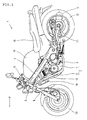
- Fig. 1 is a side view showing a motorcycle 1 equivalent to a first embodiment of the present invention.
- An arrow F points to a forward direction of a vehicle.
- the motorcycle 1 is provided with a pair of main frames 4 ranging to a head pipe 3 and inclined backward and downward, and a pair of subframes 5 which are extended downward from a lower part of the head pipe 3, which are curved backward and the each end of which is connected to the each rear end of the main frame 4.
- a power unit 2 in which an internal combustion engine 6 and a transmission 7 are integrated is mounted in triangular space formed by the main frame 4 and the subframe 5 when the triangular space is viewed from the side.
- a front fork 8 is supported by the head pipe 3 so that the front fork can be turned, a handlebar for steering 9 is mounted at the upper end of the head pipe, and a front wheel 10 is journalled to the lower end of the front fork.
- Respective front ends of a pair of rear forks 11 are supported by the respective rear ends of the main frames 4 so that the rear forks can be vertically rocked.
- a rear cushion (not shown) is mounted between the center of the rear fork 11 and the rear end of the main frame 4.
- a rear wheel 12 is supported by the rear end of the rear fork 11.
- the internal combustion engine 6 is a water-cooled V-type 2-cylinder internal combustion engine and the cylinders form a V type longitudinally.
- a crankshaft of the internal combustion engine 6 is perpendicular in a traveling direction of the vehicle and is arranged in a lateral direction of the vehicle.
- a transmission shaft of the transmission 7 is parallel to the crankshaft.
- a rear wheel driving shaft (not shown) is connected to a connecting shaft 84 shown in Fig. 2 perpendicular to an output shaft of the transmission, is extended to the rear side of the vehicle, and reaches the rear wheel 12.
- An exhaust pipe 13 connected to each exhaust port provided in a longitudinal direction of the vehicle of the two cylinders is extended in front of the internal combustion engine 6, reaches the rear of the body through the downside of the transmission 7, and is connected to an exhaust muffler 14.
- a fuel tank 17 is mounted on the upside of the main frame 4 and a seat 18 is mounted at the back of the fuel tank.
- This internal combustion engine 6 is water-cooled and cooling water the temperature of which is raised in a course for cooling the cylinder and oil is cooled by a radiator 19 attached to the front of the subframe 5.
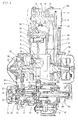
- Fig. 2 is a left side view showing the power unit 2 mounted on the motorcycle.
- An arrow F points to a forward direction when the power unit is mounted (also same in other drawings).
- a crankcase is shown in a state in which a left crankcase cover 22 is detached and the position of internal main shafts, gears and sprockets is shown.
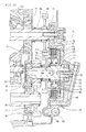
- Fig. 3 is a sectional development viewed along a line III-III shown in Fig. 2.
- a section including the rear cylinder 24R, the crankcase 30 and the transmission shaft 66 of the hydrostatic continuously variable transmission 55 is developed.
- the rear cylinder 24R holds a piston 33 connected to a left crankpin 31.
- the main crust of the power unit 2 is configured by a left crankcase 20, a right crankcase 21, a left crankcase cover 22, a right crankcase cover 23, each cylinder block 25, each cylinder head 26 and each cylinder head cover 27 respectively provided in the front cylinder 24F and the rear cylinder 24R.
- the following description of the cylinder is based upon the rear cylinder 24R.
- crankshaft 30 is rotatably supported by a left bearing 28 and a right bearing 29 held by the left and right crankcases 20, 21.
- a connecting rod 32 and the piston 33 are connected to the left crankpin 31 of the crankshaft 30 and the piston 33 is slidably held in a cylinder hole 34 of the cylinder block 25.
- a combustion chamber 35 is formed in a part opposite to the piston 33 of the cylinder head 26 and an ignition plug 36 which pierces the wall of the cylinder head 26, the end of which is opposite to the combustion chamber 35 and the rear end of which is exposed to the outside is provided.
- the exhaust port 40 and an intake port 41 are connected to the combustion chamber 35.
- the exhaust port 40 is extended forward in the front cylinder 24F and backward in the rear cylinder 24R.
- the intake port 41 is extended upward in space between both cylinders in both cylinders.
- An exhaust valve 42 is provided to the exhaust port 40 and an intake valve 43 is provided to the intake port 41.
- a camshaft 44 is provided in the cylinder head cover 27, an exhaust rocker arm shaft 45 and an intake rocker arm shaft 46 are provided on the upside of the camshaft 44, an exhaust rocker arm 47 and an intake rocker arm 48 provided to these arm shafts are driven by cams 44a, 44b on the camshaft 44, press the top of each stem of the exhaust valve 42 and the intake valve 43, and open and close each valve.
- the camshaft 44 is driven by a camshaft driving chain 51 wound on a camshaft driven sprocket 49 provided to the end of the camshaft and a camshaft driving sprocket 50 provided to the crankshaft 30.
- the hydrostatic continuously variable transmission 55 is provided at the back of the crankshaft 30.
- This transmission is acquired by integrating a centrifugal governor clutch 56, a swash plate hydraulic pump 57 and a swash plate hydraulic motor 58 via the transmission shaft 66.
- a crankshaft output gear 37 provided to the left end of the crankshaft 30 functions in a state in which it is integrally engaged with a cam torque damper 38 provided next to the crankshaft output gear and pressed by a coned disc spring.
- the crankshaft output gear 37 is a backlash noise reducing gear and is configured by a thick main gear, a thin subgear held coaxially with the main gear so that the subgear can be turned and a helical spring that presses the subgear on the main gear in a circumferential direction.
- the crankshaft output gear 37 is engaged with a transmission input gear 60 integrated with a casing 61 of the swash plate hydraulic pump 57.
- the casing 61 of the hydraulic pump 57 is rotatably supported by the left crankcase cover 22 via a ball bearing 39.
- a casing 62 of the centrifugal governor clutch 56 provided to the left end of the hydrostatic continuously variable transmission 55 is integrated with the casing 61 of the swash plate hydraulic pump 57.
- a centrifugal weight 63 for example, a steel roller or a steel ball housed in the casing 62 of the centrifugal governor clutch 56 presses a moving member 64, a hydraulic circuit switching rod clutch valve 65 connected to the moving member is moved in the transmission shaft 66, an oil passage for circulating oil discharged from the swash plate hydraulic pump 57 in the swash plate hydraulic pump 57 is closed, an oil path is switched so that the oil discharged from the swash plate hydraulic pump 57 flows toward the swash plate hydraulic motor 58, and the hydrostatic continuously variable transmission 55 is turned started.
- the swash plate hydraulic pump 57 and the swash plate hydraulic motor 58 are connected at transmission gear ratio according to an inclined condition of a swash plate 67 of the swash plate hydraulic motor 58 and shifted torque is extracted from a transmission output gear 68 fixed to the transmission shaft 66 integrated with an output part of the swash plate hydraulic motor 58.
- a tilted angle of the swash plate 67 of the swash plate hydraulic motor 58 can be changed by a swash plate driving mechanism 69 driven by an electric motor.
- the transmission gear ratio of the hydrostatic continuously variable transmission 55 can be continuously shifted by shifting the tilted angle of the swash plate 67 of the hydraulic motor 58.
- a lock-up actuator 70 acts based upon lock-up operation, an angle of the swash plate 67 of the hydraulic motor is fixed, a cylinder of the hydraulic pump 57, a cylinder of the hydraulic motor 58 and the transmission shaft 66 are integrally revolved, and efficient power transmission is made.
- Fig. 4 is a sectional view viewed along a line IV-IV shown in Fig. 2 and shows a power transmission path from the transmission shaft 66 to a link shaft 84.
- a clutch shaft 75 of an ND switching clutch 74 is rotatably supported by the right crankcase 21 and a transmission cover 73 via ball bearings 78, 79 in parallel with the transmission shaft 66.
- a gear 76 is turnably fitted to the clutch shaft 75 via clearance. The gear 76 is engaged with the transmission output gear 68 fitted on the transmission shaft 66.
- the ND switching clutch 74 is provided next to the gear 76 so as to connect and disconnect power transmission between the transmission output gear 68 and the clutch shaft 75.
- the ND switching clutch 74 is a hydraulic multiple disc clutch for switching a neutral condition and a drive condition.
- the ND switching clutch is an abbreviation of "a neutral/drive switching clutch”.
- An output shaft 80 is rotatably supported by the left crankcase 20 and the right crankcase 21 via ball bearings 87, 86 in parallel with the clutch shaft 75. Further, the connecting shaft 84 is rotatably supported by a connecting shaft support 83 provided close to the left end of the output shaft 80 perpendicularly to the output shaft 80. The connecting shaft support 83 is attached to the outside of the left crankcase 20 (also see Fig. 2).
- a gear 77 is fitted on the clutch shaft 75 next to the gear 76 of the clutch shaft 75.
- a gear 81 is fitted at the right end of the output shaft 80. The gear 81 is engaged with the gear 77 of the clutch shaft 75.
- a bevel gear 82 is integrated with the other end of the output shaft 80.
- a bevel gear 85 is integrated with the front end of the connecting shaft 84 and is engaged with the bevel gear 82 of the output shaft 80.
- a spline 84a is provided to the rear end of the connecting shaft 84 so that the rear wheel driving shaft (not shown) can be connected. The rotational output of the hydrostatic continuously variable transmission 55 is transmitted to the rear wheel via the rear wheel driving shaft by these shafts and gears.
- an oil pan 91 is provided in a lower part of the crankcase, oil stored there is sucked into an oil pump assembly 90 via an oil strainer 92 and an oil suction pipe 93, and is supplied to respective target locations.
- the oil pump 90 is driven by an oil pump driving chain 97 respectively wound on an oil pump driven sprocket 95 mounted on an oil pump shaft 94 and an oil pump driving sprocket 96 provided to the crankshaft 30.
- An oil cooler 98 and an oil filter for low pressure 99 are provided to the rear of the crankcase 20.
- Fig. 5 is a top view showing the horizontal sections of the oil pump assembly 90 and a discharge passage.
- the end of the oil suction pipe 93 is seen in a part surrounded by an oil pump case 100.
- the oil pump assembly 90 is configured by a low pressure oil pump 90L and a high pressure oil pump 90H and they are driven by one pump shaft 94.
- Oil discharged from the low pressure oil pump 90L is discharged from a low pressure oil discharge port 101 on the left side and flows into the oil cooler 98 and the oil filter 99 for low pressure via a backward oil passage L1.
- the oil cooled in the oil cooler and decontaminated in the oil filter for low pressure passage passes an outflow oil passage L2 that communicates with an oil outflow pipe 99a in the center of the oil filter for low pressure and flows rightward via an oil passage L3.
- the oil is supplied to the crankshaft and a valve train through a main gallery not shown so as to lubricate them.
- Oil discharged from the high pressure oil pump 90H is discharged from a high pressure oil discharge port 102 on the right side and flows into an oil filter for high pressure 103.
- the oil decontaminated there flows out into an outflow oil passage H1 that communicates with the center of the oil filter for high pressure, flows backward through an oil passage H2, a direction of the flow is changed rightward into a passage H3 on the way of the oil passage H2, the oil flows upward through a path not shown, and is supplied to the hydrostatic continuously variable transmission 55 so as to operate and lubricate it.
- Fig. 6 is a sectional view showing the inside of the right crankcase 21 viewed from the right side, the right crankcase cover 23 and the transmission cover 73 are removed, and shows positions of inside main shafts and oil passages.
- a reference numeral 21a denotes a fitting plane of the right crankcase cover 23
- 21b denotes a fitting plane of the transmission cover 73.
- Fig. 6 shows respective positions of the crankshaft 30, the transmission shaft 66, the ND switching clutch shaft 75 and the output shaft 80 and the oil filter for high pressure 103.
- Fig. 6 shows the oil passage for low pressure L3 and the oil passages for high pressure H1, H2, H3 respectively described above in relation to Fig. 5.
- the oil passage for low pressure L3 described above in relation to Fig. 5 connects with an oil passage L4 extended forward, an oil passage L5 extended upward, the main gallery L6 and an oil passage L7 extended to each crankshaft bearing.
- the oil passage for high pressure H3 described above in relation to Fig. 5 connects with an oil passage H4 that is extended upward and supplies operating oil and lubricating oil to the hydrostatic continuously variable transmission 55 and an oil passage H5 branched from the oil passage H4 and extended diagonally upward.
- the oil passage H5 connects with an ND switching solenoid 105 described later, the ND switching clutch 74 and a lock-up solenoid 106.
- An oil passage H6 connects with a discharge port of the lock-up solenoid 106 and operating oil is delivered to the lock-up actuator 70 shown in Fig. 3 via an oil passage H7 in a lock-up.
- Fig. 7 shows the outside face (the right surface) of the transmission cover 73.
- the ND switching solenoid 105 and the lock-up solenoid 106 are provided to the outside face.
- the oil passages H3, H4 extended to the transmission shaft 66 of the hydrostatic continuously variable transmission 55, the oil passage H5 extended to the ND switching solenoid 105 and the oil passages H6, H7 extended from the lock-up solenoid 106 to the lock-up actuator 70 are provided inside the transmission cover.
- an ND switching spool valve 110 shown in Fig. 8 is provided on the back side of the ND switching solenoid 105.
- Oil passages H8, H9 extended from the ND switching spool valve 110 to the clutch shaft 75 of the ND switching clutch 74 are provided inside a convex part of the outside face of the transmission cover 73.
- An N sensing pressure switch 107 is provided to the oil passage H8.
- An oil filler cap 108 and an oil level gauge 109 are also provided on the outside face of the transmission cover.
- the ND switching spool valve is an abbreviation of a neutral/drive switching spool valve and the N sensing pressure switch is an abbreviation of a neutral sensing pressure switch.
- Fig. 8 is a sectional view viewed along a line VIII-VIII shown in Fig. 7.
- the ND switching spool valve 110 is provided on the back side of the ND switching solenoid 105.
- Fig. 8 shows a section of its valve case 110c.
- Reference characters D, E, F, G, H in Fig. 8 correspond to reference characters of ports of the ND switching spool valve 110 shown in Fig. 11.
- Fig. 8 shows oil passages H10, H11 branched from the oil passage H5 extended to the ND switching solenoid 105 and extended to the lock-up solenoid 106.
- Fig. 9 is a back view showing the transmission cover 73.
- Fig. 9 shows a contact surface 110d opposite to the back of the transmission cover 73 of the valve case 110c of the ND switching spool valve 110 provided to the back of the transmission cover 73.
- the reference characters D, E, F, G, H in Fig. 9 correspond to the reference characters of the ports of the ND switching spool valve 110 shown in Fig. 11.
- Fig. 10 is an enlarged sectional view showing the vicinity of the ND switching clutch 74 shown in Fig. 4.
- Fig. 10 shows a section viewed along a line X-X in Fig. 7 of the transmission cover 73.
- the right end of the transmission shaft 66 of the hydrostatic continuously variable transmission 55 is rotatably supported by a ball bearing 71 held by the right crankcase 21 and a ball bearing 72 held by the transmission cover 73.
- the transmission output gear 68 is fixed between both ball bearings of the transmission shaft 66 with the transmission output gear connected via splines.
- the right end of the output shaft 80 of the power unit is rotatably supported by a ball bearing 86 held by the right crankcase 21.
- a gear 81 is fixed at the end of the output shaft 80 with the gear connected via splines.
- the ND switching clutch 74 is provided between the transmission shaft 66 and the output shaft 80.
- the clutch shaft 75 is rotatably supported by the ball bearing 78 held by the right crankcase 21 and the ball bearing 79 held by the transmission cover 73.
- the ND switching clutch 74 is configured by a bottomed cylindrical clutch outer 111 a boss 111a of which is connected to the clutch shaft 75 via splines, a clutch inner 113 which is integrated with a gear 76 supported by the clutch shaft 75 via a needle bearing 112 so that the gear can be relatively turned and an inner end of which is concentrically arranged in the clutch outer 111, a piston 115 which is slidably fitted into a cylinder hole 114 formed in the clutch outer 111, plural driving friction plates 116 which is slidably fitted to the periphery of the clutch inner 113 via splines, plural driven friction plates 117 which is slidably fitted to an inner surface of the clutch outer 111 via splines and arranged alternately with the driving friction plate, a pressed plate 118 fixed opposite to the piston 115 with a group of the friction plates 116, 117 between them, and a return spring 119 that presses the piston 115 on the bottom of the clutch outer.
- An oil pressure chamber 120 is
- a hollow part 112 is formed at the right end of the clutch shaft and the oil passages H8, H9 communicate with the hollow part 121.
- the supply of oil is controlled by the ND switching solenoid 105 and the ND switching spool valve 110.
- the hollow part 121 communicates with the oil pressure chamber 120 via an oil hole 122 provided in a radial direction of the clutch shaft 75 and an oil gateway 123 provided to the boss 111a of the clutch outer 111.
- a hollow part 124 and an oil hole 125 are also formed in a left half of the clutch shaft 75 and oil is supplied to the needle bearing 112 from an oil passage not shown via them.
- Fig. 11 is a system diagram showing a high pressure oil passage in this embodiment and shows no low pressure oil passage.
- Fig. 11 shows a flow of oil when the ND switching solenoid 105 is operated to be in the drive condition and is electrified.
- oil is sucked up to the high pressure oil pump 90H from the oil pan 91 in the lower part via the oil strainer 92 and the oil suction pipe 93 and is delivered to the high pressure oil filter 103 via the high pressure oil discharge port 102.
- a relief valve 104 is provided to the high pressure oil pump 90H so that the oil pressure of the oil discharged from the high pressure discharge port 102 is fixed.
- the oil discharged from the high pressure oil filter 103 is delivered to the hydrostatic continuously variable transmission 55 via the oil passages H1, H2, H3, H4 as operating oil and lubricating oil. Further, the oil is delivered to the ND switching solenoid 105 and the ND switching spool valve 110 via the oil passage H5 branched from the oil passage H4.
- the ND switching solenoid is electrified in the drive condition, a valve element 105a is pulled by the solenoid against the pressure of a helical spring 105b, and ports A, B are opened. At this time, oil enters a top of a valve element 110a of the ND switching spool valve from the ports A, B via a port D of the ND switching spool valve 110, presses down the valve element 110a against the pressure of a helical spring 110b, and opens ports F, G.
- Oil directly delivered to the ND switching spool valve 110 enters the ND switching spool valve via the port G, flows out from the port F via a small-diameter part of the valve element 110a, enters the oil pressure chamber 120 of the ND switching clutch 74 via the oil passages H8, H9 and the oil gateway 123, increases pressure in the oil pressure chamber, presses the piston 115 against the pressure of the return spring 119, and the ND switching clutch 74 is let in to turn into the drive condition.
- Fig. 12 is a system diagram showing the high pressure oil passage and shows a flow of oil when the ND switching solenoid 105 is switched to the neutral condition.
- the ND switching solenoid 105 is switched to the neutral condition, electrification to the solenoid is disconnected, electromagnetic force that pulls the valve element is lost, the valve element is pressed by the helical spring 105b and closes the port A, and opens the ports B, C.
- oil at the top of the ND switching spool valve 110 flows out into the crankcase via the port D of the ND switching spool valve and the ports B, C of the ND switching solenoid, and returns to the oil pan.
- the ND switching solenoid 105 has only to be electrified, however, when the ND switching solenoid 105 is not normally operated because of the failure of an electrifying system and others, an emergency bolt 126 provided to the top of the ND switching spool valve 110 is turned so as to mechanically move the valve element 110a, the ports F, G are opened, and oil can be delivered into the ND switching clutch 74.
- Fig. 13 shows a flow of oil when lock-up operation is applied to the hydrostatic continuously variable transmission in the drive condition.
- the lock-up solenoid 106 is electrified by lock-up operation while the swash plate of the hydraulic motor of the hydrostatic continuously variable transmission is turned perpendicular to the transmission shaft to be top transmission gear ratio, a valve element 106a is pulled by the solenoid 106 against the pressure of a helical spring 106b, ports J, K are opened, oil is supplied to the lock-up actuator 70 (also see Fig. 3) from the oil passages H10, H11 (also see Fig. 8) via the ports J, K and the oil passages H6, H7 (also see Fig.
- an angle of the swash plate 67 of the hydraulic motor is fixed by the action of the lock-up actuator 70, and motive power is efficiently transmitted.
- a lock-up condition is released, electrification is disconnected by operation.
- the valve element 106a is pressed by the pressure of the helical spring 106b, the port J is closed and the ports K, L are opened, oil that pressurizes the lock-up actuator 70 is discharged into the crankcase via the oil passages H6, H7 and the ports K, L, is returned to the oil pan, and the lock-up condition is released.
Landscapes
- Engineering & Computer Science (AREA)
- General Engineering & Computer Science (AREA)
- Mechanical Engineering (AREA)
- Arrangement Of Transmissions (AREA)
- Hydraulic Clutches, Magnetic Clutches, Fluid Clutches, And Fluid Joints (AREA)
- Motor Power Transmission Devices (AREA)
- General Details Of Gearings (AREA)
Abstract
Description
- The present invention relates to the transmission structure of a power unit for a vehicle.
- Oil for operating and lubricating a hydrostatic continuously variable transmission is supplied from a central hole oil passage of a transmission shaft. In related art, oil for operating a neutral/drive switching clutch is supplied through an oil passage on the downstream side of the hydrostatic continuously variable transmission acquired by extending the central hole oil passage of the transmission shaft (for example, refer to a patent document 1).
- [Patent document 1]
JP-A No. 2001-140951 - In the related art, as an oil passage for operating oil of the neutral/drive switching clutch is provided on the downstream side of an oil passage in the hydrostatic continuously variable transmission, the operating pressure of the neutral/drive switching clutch lowers because of the loss of oil pressure and the solution is desired.
- 1 The present invention is made to address the problem, and the invention according to Claim 1 relates to transmission structure of a power unit for a vehicle having a characteristic that it is provided with an oil pump that is rotated by the driving force of an internal combustion engine and supplies oil to a hydrostatic continuously variable transmission and a neutral/drive switching clutch which is arranged between the hydrostatic continuously variable transmission and a rear wheel, in which a hydraulic piston adjacent of each set of driving friction plates and driven friction plates is moved by pressure in an oil pressure chamber and which connects and disconnects the driving force in the transmission structure of the power unit for the vehicle provided with the hydrostatic continuously variable transmission for shifting and transmitting the driving force from the internal combustion engine to the rear wheel and an oil passage to the neutral/drive switching clutch is branched from an oil passage from the oil pump to the upstream side of the hydrostatic continuously variable transmission.
- The invention according to
Claim 2 has a characteristic that in the transmission structure of the power unit for the vehicle according to Claim 1, a lock-up actuator that fixes transmission gear ratio is provided to the hydrostatic continuously variable transmission and an oil passage to the lock-up actuator is branched from the oil passage to the neutral/drive switching clutch. - The invention according to Claim 3 has a characteristic that in the transmission structure of the power unit for the vehicle according to
Claim 1 or 2, the rotation axis of the hydrostatic continuously variable transmission and that of the neutral/drive switching clutch are parallel in the power unit for the vehicle and oil is supplied to both hydrostatic continuously variable transmission and the neutral/drive switching clutch via oil passages provided inside the same cover. - The invention according to
Claim 4 has a characteristic that in the transmission structure of the power unit for the vehicle according to Claim 3, the rotation axis of the hydrostatic continuously variable transmission and that of the neutral/drive switching clutch are parallel in the power unit for the vehicle and the rotation axis of the neutral/drive switching clutch is arranged on the upside of the rotation axis of the hydrostatic continuously variable transmission. - In the invention according to Claim 1, as oil is supplied to the neutral/drive switching clutch via the oil passage branched from the oil passage on the upstream side of the hydrostatic continuously variable transmission, there is no resistance in an internal passage of the hydrostatic continuously variable transmission, the connection and the disconnection of the neutral/drive switching clutch can be accelerated, and smooth starting operation is enabled.
- In the invention according to
Claim 2, as both accessories utilize the pressure of oil, the oil passage from the oil pump is used for both and can be simplified, and the oil passage can be miniaturized. - In the invention according to Claim 3, as the oil passages are provided inside the same cover, the oil passages can be shortened and compacted.
- In the invention according to
Claim 4, as the starting clutch is located above, the oil pressure of operating oil when the clutch is let out can be promptly reduced and clutch disengagement performance is enhanced. - Fig. 1 is a side view showing a motorcycle 1 equivalent to one embodiment of the present invention.
- Fig. 2 is a left side view showing a
power unit 2 mounted in the motorcycle. - Fig. 3 is a sectional development viewed along a line III-III shown in Fig. 2.
- Fig. 4 is a sectional view viewed along a line IV-IV shown in Fig. 2.
- Fig. 5 is a top view showing horizontal sections of an
oil pump assembly 90 and a discharge passage. - Fig. 6 is a sectional view showing the inside of a
crankcase 20 viewed from the right side. - Fig. 7 shows the outside face (the right surface) of a
transmission cover 73. - Fig. 8 is a sectional view viewed along a line VIII-VIII shown in Fig. 7.
- Fig. 9 is a back view showing the
transmission cover 73. - Fig. 10 is an enlarged sectional view showing an
ND switching clutch 74. - Fig. 11 is a system diagram showing a high pressure oil passage and shows a flow of oil when an
ND switching solenoid 105 is operated in a drive condition. - Fig. 12 is a system diagram showing the high pressure oil passage and shows a flow of oil when the
ND switching solenoid 105 is switched to a neutral condition. - Fig. 13 shows a flow of oil when lock-up operation is applied to a hydrostatic continuously variable transmission in the drive condition.
- Fig. 1 is a side view showing a motorcycle 1 equivalent to a first embodiment of the present invention. An arrow F points to a forward direction of a vehicle. The motorcycle 1 is provided with a pair of
main frames 4 ranging to a head pipe 3 and inclined backward and downward, and a pair ofsubframes 5 which are extended downward from a lower part of the head pipe 3, which are curved backward and the each end of which is connected to the each rear end of themain frame 4. - A
power unit 2 in which aninternal combustion engine 6 and atransmission 7 are integrated is mounted in triangular space formed by themain frame 4 and thesubframe 5 when the triangular space is viewed from the side. A front fork 8 is supported by the head pipe 3 so that the front fork can be turned, a handlebar forsteering 9 is mounted at the upper end of the head pipe, and afront wheel 10 is journalled to the lower end of the front fork. Respective front ends of a pair ofrear forks 11 are supported by the respective rear ends of themain frames 4 so that the rear forks can be vertically rocked. A rear cushion (not shown) is mounted between the center of therear fork 11 and the rear end of themain frame 4. Arear wheel 12 is supported by the rear end of therear fork 11. - The
internal combustion engine 6 is a water-cooled V-type 2-cylinder internal combustion engine and the cylinders form a V type longitudinally. A crankshaft of theinternal combustion engine 6 is perpendicular in a traveling direction of the vehicle and is arranged in a lateral direction of the vehicle. A transmission shaft of thetransmission 7 is parallel to the crankshaft. A rear wheel driving shaft (not shown) is connected to a connectingshaft 84 shown in Fig. 2 perpendicular to an output shaft of the transmission, is extended to the rear side of the vehicle, and reaches therear wheel 12. - An
exhaust pipe 13 connected to each exhaust port provided in a longitudinal direction of the vehicle of the two cylinders is extended in front of theinternal combustion engine 6, reaches the rear of the body through the downside of thetransmission 7, and is connected to anexhaust muffler 14. Afuel tank 17 is mounted on the upside of themain frame 4 and aseat 18 is mounted at the back of the fuel tank. Thisinternal combustion engine 6 is water-cooled and cooling water the temperature of which is raised in a course for cooling the cylinder and oil is cooled by aradiator 19 attached to the front of thesubframe 5. - Fig. 2 is a left side view showing the
power unit 2 mounted on the motorcycle. An arrow F points to a forward direction when the power unit is mounted (also same in other drawings). As afront cylinder 24F and arear cylinder 24R have the same internal structure, only the section of therear cylinder 24R is shown. A crankcase is shown in a state in which aleft crankcase cover 22 is detached and the position of internal main shafts, gears and sprockets is shown. - Fig. 3 is a sectional development viewed along a line III-III shown in Fig. 2. In the drawing, a section including the
rear cylinder 24R, thecrankcase 30 and thetransmission shaft 66 of the hydrostatic continuouslyvariable transmission 55 is developed. Therear cylinder 24R holds apiston 33 connected to aleft crankpin 31. - As shown in Figs. 2 and 3, the main crust of the
power unit 2 is configured by aleft crankcase 20, aright crankcase 21, aleft crankcase cover 22, aright crankcase cover 23, eachcylinder block 25, eachcylinder head 26 and eachcylinder head cover 27 respectively provided in thefront cylinder 24F and therear cylinder 24R. The following description of the cylinder is based upon therear cylinder 24R. - As shown in Fig. 3, the
crankshaft 30 is rotatably supported by a left bearing 28 and a right bearing 29 held by the left andright crankcases rod 32 and thepiston 33 are connected to theleft crankpin 31 of thecrankshaft 30 and thepiston 33 is slidably held in acylinder hole 34 of thecylinder block 25. Acombustion chamber 35 is formed in a part opposite to thepiston 33 of thecylinder head 26 and anignition plug 36 which pierces the wall of thecylinder head 26, the end of which is opposite to thecombustion chamber 35 and the rear end of which is exposed to the outside is provided. - As shown in Fig. 2, the
exhaust port 40 and anintake port 41 are connected to thecombustion chamber 35. Theexhaust port 40 is extended forward in thefront cylinder 24F and backward in therear cylinder 24R. Theintake port 41 is extended upward in space between both cylinders in both cylinders. Anexhaust valve 42 is provided to theexhaust port 40 and anintake valve 43 is provided to theintake port 41. Acamshaft 44 is provided in thecylinder head cover 27, an exhaustrocker arm shaft 45 and an intakerocker arm shaft 46 are provided on the upside of thecamshaft 44, anexhaust rocker arm 47 and anintake rocker arm 48 provided to these arm shafts are driven bycams 44a, 44b on thecamshaft 44, press the top of each stem of theexhaust valve 42 and theintake valve 43, and open and close each valve. As shown in Fig. 3, thecamshaft 44 is driven by acamshaft driving chain 51 wound on a camshaft drivensprocket 49 provided to the end of the camshaft and acamshaft driving sprocket 50 provided to thecrankshaft 30. - As shown in Fig. 3, the hydrostatic continuously
variable transmission 55 is provided at the back of thecrankshaft 30. This transmission is acquired by integrating acentrifugal governor clutch 56, a swash platehydraulic pump 57 and a swash platehydraulic motor 58 via thetransmission shaft 66. Acrankshaft output gear 37 provided to the left end of thecrankshaft 30 functions in a state in which it is integrally engaged with acam torque damper 38 provided next to the crankshaft output gear and pressed by a coned disc spring. Thecrankshaft output gear 37 is a backlash noise reducing gear and is configured by a thick main gear, a thin subgear held coaxially with the main gear so that the subgear can be turned and a helical spring that presses the subgear on the main gear in a circumferential direction. Thecrankshaft output gear 37 is engaged with atransmission input gear 60 integrated with acasing 61 of the swash platehydraulic pump 57. Thecasing 61 of thehydraulic pump 57 is rotatably supported by theleft crankcase cover 22 via a ball bearing 39. - A
casing 62 of the centrifugal governor clutch 56 provided to the left end of the hydrostatic continuouslyvariable transmission 55 is integrated with thecasing 61 of the swash platehydraulic pump 57. When the revolution speed of thecasing 61 of the swash platehydraulic pump 57 increases, compared with predetermined speed, a centrifugal weight 63 (for example, a steel roller or a steel ball) housed in thecasing 62 of the centrifugal governor clutch 56 presses a movingmember 64, a hydraulic circuit switching rodclutch valve 65 connected to the moving member is moved in thetransmission shaft 66, an oil passage for circulating oil discharged from the swash platehydraulic pump 57 in the swash platehydraulic pump 57 is closed, an oil path is switched so that the oil discharged from the swash platehydraulic pump 57 flows toward the swash platehydraulic motor 58, and the hydrostatic continuouslyvariable transmission 55 is turned started. - The swash plate
hydraulic pump 57 and the swash platehydraulic motor 58 are connected at transmission gear ratio according to an inclined condition of aswash plate 67 of the swash platehydraulic motor 58 and shifted torque is extracted from atransmission output gear 68 fixed to thetransmission shaft 66 integrated with an output part of the swash platehydraulic motor 58. - A tilted angle of the
swash plate 67 of the swash platehydraulic motor 58 can be changed by a swashplate driving mechanism 69 driven by an electric motor. The transmission gear ratio of the hydrostatic continuouslyvariable transmission 55 can be continuously shifted by shifting the tilted angle of theswash plate 67 of thehydraulic motor 58. When the inclination of theswash plate 67 of the hydraulic motor is zero, that is, the swash plate of the hydraulic motor is perpendicular to the transmission shaft, top transmission gear ratio is acquired. At this time, a lock-upactuator 70 acts based upon lock-up operation, an angle of theswash plate 67 of the hydraulic motor is fixed, a cylinder of thehydraulic pump 57, a cylinder of thehydraulic motor 58 and thetransmission shaft 66 are integrally revolved, and efficient power transmission is made. - Fig. 4 is a sectional view viewed along a line IV-IV shown in Fig. 2 and shows a power transmission path from the
transmission shaft 66 to alink shaft 84. Aclutch shaft 75 of anND switching clutch 74 is rotatably supported by theright crankcase 21 and atransmission cover 73 viaball bearings transmission shaft 66. Agear 76 is turnably fitted to theclutch shaft 75 via clearance. Thegear 76 is engaged with thetransmission output gear 68 fitted on thetransmission shaft 66. TheND switching clutch 74 is provided next to thegear 76 so as to connect and disconnect power transmission between thetransmission output gear 68 and theclutch shaft 75. TheND switching clutch 74 is a hydraulic multiple disc clutch for switching a neutral condition and a drive condition. The ND switching clutch is an abbreviation of "a neutral/drive switching clutch". - An
output shaft 80 is rotatably supported by theleft crankcase 20 and theright crankcase 21 viaball bearings clutch shaft 75. Further, the connectingshaft 84 is rotatably supported by a connectingshaft support 83 provided close to the left end of theoutput shaft 80 perpendicularly to theoutput shaft 80. The connectingshaft support 83 is attached to the outside of the left crankcase 20 (also see Fig. 2). - A
gear 77 is fitted on theclutch shaft 75 next to thegear 76 of theclutch shaft 75. Agear 81 is fitted at the right end of theoutput shaft 80. Thegear 81 is engaged with thegear 77 of theclutch shaft 75. Abevel gear 82 is integrated with the other end of theoutput shaft 80. Abevel gear 85 is integrated with the front end of the connectingshaft 84 and is engaged with thebevel gear 82 of theoutput shaft 80. Aspline 84a is provided to the rear end of the connectingshaft 84 so that the rear wheel driving shaft (not shown) can be connected. The rotational output of the hydrostatic continuouslyvariable transmission 55 is transmitted to the rear wheel via the rear wheel driving shaft by these shafts and gears. - As shown in Fig. 2, an
oil pan 91 is provided in a lower part of the crankcase, oil stored there is sucked into anoil pump assembly 90 via anoil strainer 92 and anoil suction pipe 93, and is supplied to respective target locations. Theoil pump 90 is driven by an oil pump driving chain 97 respectively wound on an oil pump drivensprocket 95 mounted on anoil pump shaft 94 and an oilpump driving sprocket 96 provided to thecrankshaft 30. Anoil cooler 98 and an oil filter forlow pressure 99 are provided to the rear of thecrankcase 20. - Fig. 5 is a top view showing the horizontal sections of the
oil pump assembly 90 and a discharge passage. The end of theoil suction pipe 93 is seen in a part surrounded by anoil pump case 100. Theoil pump assembly 90 is configured by a lowpressure oil pump 90L and a highpressure oil pump 90H and they are driven by onepump shaft 94. - Oil discharged from the low
pressure oil pump 90L is discharged from a low pressureoil discharge port 101 on the left side and flows into theoil cooler 98 and theoil filter 99 for low pressure via a backward oil passage L1. The oil cooled in the oil cooler and decontaminated in the oil filter for low pressure passage passes an outflow oil passage L2 that communicates with anoil outflow pipe 99a in the center of the oil filter for low pressure and flows rightward via an oil passage L3. The oil is supplied to the crankshaft and a valve train through a main gallery not shown so as to lubricate them. - Oil discharged from the high
pressure oil pump 90H is discharged from a high pressureoil discharge port 102 on the right side and flows into an oil filter forhigh pressure 103. The oil decontaminated there flows out into an outflow oil passage H1 that communicates with the center of the oil filter for high pressure, flows backward through an oil passage H2, a direction of the flow is changed rightward into a passage H3 on the way of the oil passage H2, the oil flows upward through a path not shown, and is supplied to the hydrostatic continuouslyvariable transmission 55 so as to operate and lubricate it. - Fig. 6 is a sectional view showing the inside of the
right crankcase 21 viewed from the right side, theright crankcase cover 23 and thetransmission cover 73 are removed, and shows positions of inside main shafts and oil passages. As shown in Fig. 6, areference numeral 21a denotes a fitting plane of theright crankcase cover transmission cover 73. Fig. 6 shows respective positions of thecrankshaft 30, thetransmission shaft 66, the ND switchingclutch shaft 75 and theoutput shaft 80 and the oil filter forhigh pressure 103. Besides, Fig. 6 shows the oil passage for low pressure L3 and the oil passages for high pressure H1, H2, H3 respectively described above in relation to Fig. 5. The oil passage for low pressure L3 described above in relation to Fig. 5 connects with an oil passage L4 extended forward, an oil passage L5 extended upward, the main gallery L6 and an oil passage L7 extended to each crankshaft bearing. The oil passage for high pressure H3 described above in relation to Fig. 5 connects with an oil passage H4 that is extended upward and supplies operating oil and lubricating oil to the hydrostatic continuouslyvariable transmission 55 and an oil passage H5 branched from the oil passage H4 and extended diagonally upward. The oil passage H5 connects with anND switching solenoid 105 described later, theND switching clutch 74 and a lock-upsolenoid 106. An oil passage H6 connects with a discharge port of the lock-upsolenoid 106 and operating oil is delivered to the lock-upactuator 70 shown in Fig. 3 via an oil passage H7 in a lock-up. - Fig. 7 shows the outside face (the right surface) of the
transmission cover 73. TheND switching solenoid 105 and the lock-upsolenoid 106 are provided to the outside face. The oil passages H3, H4 extended to thetransmission shaft 66 of the hydrostatic continuouslyvariable transmission 55, the oil passage H5 extended to theND switching solenoid 105 and the oil passages H6, H7 extended from the lock-upsolenoid 106 to the lock-upactuator 70 are provided inside the transmission cover. Though it is not shown in Fig. 7, an NDswitching spool valve 110 shown in Fig. 8 is provided on the back side of theND switching solenoid 105. Oil passages H8, H9 extended from the ND switchingspool valve 110 to theclutch shaft 75 of theND switching clutch 74 are provided inside a convex part of the outside face of thetransmission cover 73. An Nsensing pressure switch 107 is provided to the oil passage H8. Anoil filler cap 108 and anoil level gauge 109 are also provided on the outside face of the transmission cover. The ND switching spool valve is an abbreviation of a neutral/drive switching spool valve and the N sensing pressure switch is an abbreviation of a neutral sensing pressure switch. - Fig. 8 is a sectional view viewed along a line VIII-VIII shown in Fig. 7. The ND
switching spool valve 110 is provided on the back side of theND switching solenoid 105. Fig. 8 shows a section of itsvalve case 110c. Reference characters D, E, F, G, H in Fig. 8 correspond to reference characters of ports of the ND switchingspool valve 110 shown in Fig. 11. Besides, Fig. 8 shows oil passages H10, H11 branched from the oil passage H5 extended to theND switching solenoid 105 and extended to the lock-upsolenoid 106. - Fig. 9 is a back view showing the
transmission cover 73. Fig. 9 shows acontact surface 110d opposite to the back of thetransmission cover 73 of thevalve case 110c of the ND switchingspool valve 110 provided to the back of thetransmission cover 73. The reference characters D, E, F, G, H in Fig. 9 correspond to the reference characters of the ports of the ND switchingspool valve 110 shown in Fig. 11. - Fig. 10 is an enlarged sectional view showing the vicinity of the ND switching clutch 74 shown in Fig. 4. Fig. 10 shows a section viewed along a line X-X in Fig. 7 of the
transmission cover 73. As shown in an upper part of Fig. 10, the right end of thetransmission shaft 66 of the hydrostatic continuouslyvariable transmission 55 is rotatably supported by aball bearing 71 held by theright crankcase 21 and aball bearing 72 held by thetransmission cover 73. Thetransmission output gear 68 is fixed between both ball bearings of thetransmission shaft 66 with the transmission output gear connected via splines. As shown in a lower part of Fig. 10, the right end of theoutput shaft 80 of the power unit is rotatably supported by aball bearing 86 held by theright crankcase 21. Agear 81 is fixed at the end of theoutput shaft 80 with the gear connected via splines. TheND switching clutch 74 is provided between thetransmission shaft 66 and theoutput shaft 80. Theclutch shaft 75 is rotatably supported by theball bearing 78 held by theright crankcase 21 and theball bearing 79 held by thetransmission cover 73. - The
ND switching clutch 74 is configured by a bottomed cylindrical clutch outer 111 aboss 111a of which is connected to theclutch shaft 75 via splines, a clutch inner 113 which is integrated with agear 76 supported by theclutch shaft 75 via aneedle bearing 112 so that the gear can be relatively turned and an inner end of which is concentrically arranged in the clutch outer 111, apiston 115 which is slidably fitted into a cylinder hole 114 formed in the clutch outer 111, pluraldriving friction plates 116 which is slidably fitted to the periphery of the clutch inner 113 via splines, plural drivenfriction plates 117 which is slidably fitted to an inner surface of the clutch outer 111 via splines and arranged alternately with the driving friction plate, apressed plate 118 fixed opposite to thepiston 115 with a group of thefriction plates return spring 119 that presses thepiston 115 on the bottom of the clutch outer. Anoil pressure chamber 120 is formed between the bottom of the clutch outer and thepiston 115. - A
hollow part 112 is formed at the right end of the clutch shaft and the oil passages H8, H9 communicate with thehollow part 121. In the oil passages H9, H8, the supply of oil is controlled by theND switching solenoid 105 and the ND switchingspool valve 110. Thehollow part 121 communicates with theoil pressure chamber 120 via anoil hole 122 provided in a radial direction of theclutch shaft 75 and anoil gateway 123 provided to theboss 111a of the clutch outer 111. Ahollow part 124 and anoil hole 125 are also formed in a left half of theclutch shaft 75 and oil is supplied to theneedle bearing 112 from an oil passage not shown via them. - When the
ND switching solenoid 105 shown in Fig. 10 is electrified by operation by a rider of the vehicle and oil supplied via the ND switchingspool valve 110 is supplied to theoil pressure chamber 120 from the oil passages H8, H9 via thehollow part 121, the group of thefriction plates piston 115 and the pressedplate 118 and motive power transmitted to thegear 76 is transmitted to theclutch shaft 75 via theND switching clutch 74. Thegear 77 fitted on theclutch shaft 75 is engaged with thegear 81 fitted on theoutput shaft 80 and hereby, the motive power transmitted to theclutch shaft 75 is transmitted to theoutput shaft 80. - Fig. 11 is a system diagram showing a high pressure oil passage in this embodiment and shows no low pressure oil passage. Fig. 11 shows a flow of oil when the
ND switching solenoid 105 is operated to be in the drive condition and is electrified. As shown in Fig. 11, oil is sucked up to the highpressure oil pump 90H from theoil pan 91 in the lower part via theoil strainer 92 and theoil suction pipe 93 and is delivered to the highpressure oil filter 103 via the high pressureoil discharge port 102. Arelief valve 104 is provided to the highpressure oil pump 90H so that the oil pressure of the oil discharged from the highpressure discharge port 102 is fixed. The oil discharged from the highpressure oil filter 103 is delivered to the hydrostatic continuouslyvariable transmission 55 via the oil passages H1, H2, H3, H4 as operating oil and lubricating oil. Further, the oil is delivered to theND switching solenoid 105 and the ND switchingspool valve 110 via the oil passage H5 branched from the oil passage H4. - The ND switching solenoid is electrified in the drive condition, a
valve element 105a is pulled by the solenoid against the pressure of ahelical spring 105b, and ports A, B are opened. At this time, oil enters a top of avalve element 110a of the ND switching spool valve from the ports A, B via a port D of the ND switchingspool valve 110, presses down thevalve element 110a against the pressure of ahelical spring 110b, and opens ports F, G. Oil directly delivered to the ND switchingspool valve 110 enters the ND switching spool valve via the port G, flows out from the port F via a small-diameter part of thevalve element 110a, enters theoil pressure chamber 120 of theND switching clutch 74 via the oil passages H8, H9 and theoil gateway 123, increases pressure in the oil pressure chamber, presses thepiston 115 against the pressure of thereturn spring 119, and theND switching clutch 74 is let in to turn into the drive condition. - Fig. 12 is a system diagram showing the high pressure oil passage and shows a flow of oil when the
ND switching solenoid 105 is switched to the neutral condition. When theND switching solenoid 105 is switched to the neutral condition, electrification to the solenoid is disconnected, electromagnetic force that pulls the valve element is lost, the valve element is pressed by thehelical spring 105b and closes the port A, and opens the ports B, C. Then, oil at the top of the ND switchingspool valve 110 flows out into the crankcase via the port D of the ND switching spool valve and the ports B, C of the ND switching solenoid, and returns to the oil pan. When pressure at the top of the ND switchingspool valve 110 is lost, thevalve element 110a is pressed and moved by thehelical spring 110b, closes the port G, and opens the ports E, F. Then, oil in theoil pressure chamber 120 of theND switching clutch 74 is pressed by thepiston 115 pressed by thereturn spring 119, reversely flows through theoil gateway 123 and the oil passages H9, H8, flows out into the crankcase via the ports F, E of the ND switching spool valve, and returns to the oil pan. Hereby, theND switching clutch 74 is let out to turn into the neutral condition. The Nsensing pressure switch 107 is provided on the way of the oil passage H8. This pressure switch prevents more oil than oil required in an oil passage system in the switching clutch that communicates with the continuously variable transmission from flowing out and smoothes the motion of the switching clutch when it is restarted. - To turn the system into the drive condition again, the
ND switching solenoid 105 has only to be electrified, however, when theND switching solenoid 105 is not normally operated because of the failure of an electrifying system and others, anemergency bolt 126 provided to the top of the ND switchingspool valve 110 is turned so as to mechanically move thevalve element 110a, the ports F, G are opened, and oil can be delivered into theND switching clutch 74. - Fig. 13 shows a flow of oil when lock-up operation is applied to the hydrostatic continuously variable transmission in the drive condition. When the lock-up
solenoid 106 is electrified by lock-up operation while the swash plate of the hydraulic motor of the hydrostatic continuously variable transmission is turned perpendicular to the transmission shaft to be top transmission gear ratio, avalve element 106a is pulled by thesolenoid 106 against the pressure of ahelical spring 106b, ports J, K are opened, oil is supplied to the lock-up actuator 70 (also see Fig. 3) from the oil passages H10, H11 (also see Fig. 8) via the ports J, K and the oil passages H6, H7 (also see Fig. 6), an angle of theswash plate 67 of the hydraulic motor is fixed by the action of the lock-upactuator 70, and motive power is efficiently transmitted. When a lock-up condition is released, electrification is disconnected by operation. At this time, as thevalve element 106a is pressed by the pressure of thehelical spring 106b, the port J is closed and the ports K, L are opened, oil that pressurizes the lock-upactuator 70 is discharged into the crankcase via the oil passages H6, H7 and the ports K, L, is returned to the oil pan, and the lock-up condition is released. - As described above in detail, the following effect is produced by the transmission structure of the power unit for the vehicle in this embodiment.
- (1) As oil is supplied to the ND switching clutch 74 from the oil passage H5 branched from the oil passage H4 on the upstream side of the hydrostatic continuously
variable transmission 55, there is no resistance in the internal passages of the hydrostatic continuouslyvariable transmission 55, the connection of the ND switching clutch 74 can be accelerated and smooth starting operation is enabled. - (2) The oil passages H10, H11 that connects with the lock-up
actuator 70 are branched from the oil passage H5 that connects with theND switching clutch 74. As both accessories utilize the pressure of oil, the oil passage from theoil pump 90H is used for both and can be simplified, and the oil passages can be miniaturized. - (3) The rotation axis of the hydrostatic continuously
variable transmission 55 and that of theND switching clutch 74 are parallel and the end of the ND switching clutch is covered with thetransmission cover 73. As the oil passage H4 that connects with the hydrostatic continuouslyvariable transmission 55 and the oil passages H5, H8, H9 that connect with theND switching clutch 74 are both provided inside thetransmission cover 73, the oil passages can be shortened and compacted. - (4) As the starting clutch is located above, the oil pressure of operating oil when the clutch is let out can be promptly reduced and clutch disengagement performance is enhanced.
-
- 2... Power unit,
- 6... Internal combustion engine,
- 7... Transmission,
- 12... Rear wheel,
- 55... Hydrostatic continuously variable transmission,
- 66... Transmission shaft,
- 67... Swash plate of hydraulic motor,
- 69... Swash plate driving mechanism,
- 70... Lock-up actuator,
- 73... Transmission cover,
- 74... ND switching clutch,
- 75... Clutch shaft,
- 90... Oil pump assembly,
- 90L... Low pressure oil pump,
- 90H... High pressure oil pump,
- 102... High pressure oil discharge port,
- 103... High pressure oil filter,
- 105... ND switching solenoid,
- 105a... Valve element,
- 105b... Helical spring,
- 106... Lock-up solenoid,
- 106a... Valve element,
- 106b... Helical spring,
- 110... ND switching spool valve,
- 110a... Valve element,
- 110b... Helical spring,
- 110c... valve case,
- 111... Clutch outer,
- 111a... Boss,
- 112... Needle bearing,
- 113... Clutch inner,
- 114... Cylinder hole,
- 115... Piston,
- 116... Driving friction plate,
- 117... Driven friction plate,
- 118... Pressed plate,
- 119... Return spring,
- 120... Oil pressure chamber,
- 121... Hollow part,
- 122... Oil hole,
- 123... Oil gateway
Claims (4)
- Transmission structure of a power unit (2) for a vehicle provided with a hydrostatic continuously variable transmission (55) for shifting and transmitting driving force from an internal combustion engine (6) to a rear wheel (12), comprising:an oil pump that is rotated by the driving force of the internal combustion engine (6) and supplies oil to the hydrostatic continuously variable transmission (55); anda neutral/drive switching clutch (74) which is arranged between the hydrostatic continuously variable transmission (55) and the rear wheel (12), in which a hydraulic piston adjacent to each set of driving friction plates (116) and driven friction plates(117) is moved by pressure in an oil pressure chamber(120), the neutral/drive switching clutch (74) connecting and disconnecting the driving force,wherein an oil passage to the neutral/drive switching clutch (74) is branched from an oil passage from the oil pump to the upstream side of the hydrostatic continuously variable transmission (55).
- The transmission structure of the power unit (2) for the vehicle according to Claim 1,
wherein: a lock-up actuator (70) that fixes transmission gear ratio is provided to the hydrostatic continuously variable transmission (55); and
an oil passage to the lock-up actuator (70) is branched from the oil passage to the neutral/drive switching clutch (74). - The transmission structure of the power unit (2) for the vehicle according to Claim 1 or 2,
wherein: in the power unit (2) for the vehicle, the rotation axis of the hydrostatic continuously variable transmission (55) and that of the neutral/drive switching clutch (74) are parallel; and
oil is supplied to both the hydrostatic continuously variable transmission (55) and the neutral/drive switching clutch (74) via oil passages provided inside the same cover. - The transmission structure of the power unit (2) for the vehicle according to Claim 1, 2 or 3,
wherein: in the power unit (2) for the vehicle, the rotation axis of the hydrostatic continuously variable transmission (55) and that of the neutral/drive switching clutch (74) are parallel; and
the rotation axis of the neutral/drive switching clutch (74) is arranged on the upside of the rotation axis of the hydrostatic continuously variable transmission (55).
Applications Claiming Priority (1)
| Application Number | Priority Date | Filing Date | Title |
|---|---|---|---|
| JP2006121558A JP2007290580A (en) | 2006-04-26 | 2006-04-26 | Transmission structure of vehicle power unit |
Publications (2)
| Publication Number | Publication Date |
|---|---|
| EP1850036A1 true EP1850036A1 (en) | 2007-10-31 |
| EP1850036B1 EP1850036B1 (en) | 2011-07-27 |
Family
ID=38051570
Family Applications (1)
| Application Number | Title | Priority Date | Filing Date |
|---|---|---|---|
| EP07104612A Not-in-force EP1850036B1 (en) | 2006-04-26 | 2007-03-21 | Transmission Structure of Power Unit for Vehicle |
Country Status (5)
| Country | Link |
|---|---|
| US (1) | US20070251229A1 (en) |
| EP (1) | EP1850036B1 (en) |
| JP (1) | JP2007290580A (en) |
| CA (1) | CA2584308C (en) |
| ES (1) | ES2366742T3 (en) |
Cited By (3)
| Publication number | Priority date | Publication date | Assignee | Title |
|---|---|---|---|---|
| ES2376617A1 (en) * | 2008-02-20 | 2012-03-15 | Honda Motor Co., Ltd. | Vehicle provided with torque damper |
| ES2376869A1 (en) * | 2008-02-26 | 2012-03-20 | Honda Motor Co. Ltd. | Oil quantity monitoring system for motorcycle |
| CN108343684A (en) * | 2017-01-24 | 2018-07-31 | 本田技研工业株式会社 | Hydraulic clutch apparatus |
Families Citing this family (8)
| Publication number | Priority date | Publication date | Assignee | Title |
|---|---|---|---|---|
| JP4608536B2 (en) * | 2007-11-30 | 2011-01-12 | 本田技研工業株式会社 | Power unit for motorcycle |
| JP5053113B2 (en) | 2008-01-31 | 2012-10-17 | 本田技研工業株式会社 | Switch open / close detection device |
| JP5015028B2 (en) * | 2008-02-20 | 2012-08-29 | 本田技研工業株式会社 | Power unit with torque damper |
| US8074451B2 (en) | 2008-06-02 | 2011-12-13 | Caterpillar Inc. | Electric motor actuation of a hydrostatic pump |
| JP2014065465A (en) * | 2012-09-27 | 2014-04-17 | Honda Motor Co Ltd | Internal combustion engine for motorcycle |
| US10961882B2 (en) * | 2017-03-23 | 2021-03-30 | Honda Motor Co., Ltd. | Internal combustion engine |
| CN114894372B (en) * | 2022-03-21 | 2023-09-29 | 中国北方车辆研究所 | A transmission pressure measuring device |
| JP7831233B2 (en) | 2022-11-09 | 2026-03-17 | トヨタ自動車株式会社 | A drive system for a vehicle and a vehicle equipped with it. |
Citations (3)
| Publication number | Priority date | Publication date | Assignee | Title |
|---|---|---|---|---|
| JP2001140951A (en) | 1999-11-19 | 2001-05-22 | Honda Motor Co Ltd | Vehicle transmission |
| US20050198952A1 (en) * | 2004-03-12 | 2005-09-15 | Honda Motor Co., Ltd. | Hydrostatic continuously variable transmission |
| DE102005010015A1 (en) * | 2004-03-12 | 2005-10-06 | Honda Motor Co., Ltd. | Coupling device for a hydrostatic continuously variable transmission |
Family Cites Families (9)
| Publication number | Priority date | Publication date | Assignee | Title |
|---|---|---|---|---|
| JPS61162643U (en) * | 1985-03-29 | 1986-10-08 | ||
| JP3971082B2 (en) * | 2000-05-11 | 2007-09-05 | 本田技研工業株式会社 | Lubricating device for internal combustion engine |
| JP4183975B2 (en) * | 2002-05-24 | 2008-11-19 | 川崎重工業株式会社 | Four-wheel vehicle for rough terrain |
| JP4070554B2 (en) * | 2002-09-18 | 2008-04-02 | 本田技研工業株式会社 | Power device for vehicle with internal combustion engine |
| JP2005256977A (en) * | 2004-03-12 | 2005-09-22 | Honda Motor Co Ltd | Hydrostatic continuously variable transmission |
| JP2005319920A (en) * | 2004-05-10 | 2005-11-17 | Fuji Heavy Ind Ltd | Engine power transmission device |
| JP4761301B2 (en) * | 2004-09-01 | 2011-08-31 | 株式会社 神崎高級工機製作所 | Work vehicle equipped with hydraulic transmission |
| US7942645B2 (en) * | 2004-11-26 | 2011-05-17 | Honda Motor Co., Ltd. | Oil pump assembly |
| JP4451329B2 (en) * | 2005-02-08 | 2010-04-14 | 本田技研工業株式会社 | Clutch mechanism of hydrostatic continuously variable transmission |
-
2006
- 2006-04-26 JP JP2006121558A patent/JP2007290580A/en active Pending
-
2007
- 2007-03-21 EP EP07104612A patent/EP1850036B1/en not_active Not-in-force
- 2007-03-21 ES ES07104612T patent/ES2366742T3/en active Active
- 2007-04-10 CA CA002584308A patent/CA2584308C/en not_active Expired - Fee Related
- 2007-04-24 US US11/790,248 patent/US20070251229A1/en not_active Abandoned
Patent Citations (4)
| Publication number | Priority date | Publication date | Assignee | Title |
|---|---|---|---|---|
| JP2001140951A (en) | 1999-11-19 | 2001-05-22 | Honda Motor Co Ltd | Vehicle transmission |
| US6381957B1 (en) * | 1999-11-19 | 2002-05-07 | Honda Giken Kogyo Kabushiki Kaisha | Vehicle transmission |
| US20050198952A1 (en) * | 2004-03-12 | 2005-09-15 | Honda Motor Co., Ltd. | Hydrostatic continuously variable transmission |
| DE102005010015A1 (en) * | 2004-03-12 | 2005-10-06 | Honda Motor Co., Ltd. | Coupling device for a hydrostatic continuously variable transmission |
Cited By (5)
| Publication number | Priority date | Publication date | Assignee | Title |
|---|---|---|---|---|
| ES2376617A1 (en) * | 2008-02-20 | 2012-03-15 | Honda Motor Co., Ltd. | Vehicle provided with torque damper |
| ES2376869A1 (en) * | 2008-02-26 | 2012-03-20 | Honda Motor Co. Ltd. | Oil quantity monitoring system for motorcycle |
| CN108343684A (en) * | 2017-01-24 | 2018-07-31 | 本田技研工业株式会社 | Hydraulic clutch apparatus |
| CN108343684B (en) * | 2017-01-24 | 2019-10-25 | 本田技研工业株式会社 | hydraulic clutch device |
| US10663014B2 (en) | 2017-01-24 | 2020-05-26 | Honda Motor Co., Ltd. | Hydraulic clutch device |
Also Published As
| Publication number | Publication date |
|---|---|
| CA2584308A1 (en) | 2007-10-26 |
| US20070251229A1 (en) | 2007-11-01 |
| CA2584308C (en) | 2009-12-08 |
| EP1850036B1 (en) | 2011-07-27 |
| ES2366742T3 (en) | 2011-10-25 |
| JP2007290580A (en) | 2007-11-08 |
Similar Documents
| Publication | Publication Date | Title |
|---|---|---|
| EP1850036B1 (en) | Transmission Structure of Power Unit for Vehicle | |
| US7578277B2 (en) | Pump drive structure of water-cooled internal combustion engine | |
| US8002653B2 (en) | Power unit having engine and continuously variable transmission, configuration thereof, and vehicle incorporating same | |
| US7559307B2 (en) | Oil filter mounting structure in internal combustion engine | |
| US8925500B2 (en) | Casing structure of a water-cooled internal combustion engine | |
| JPS63129107A (en) | Engine timing transmission | |
| JP4357322B2 (en) | Power unit for saddle-ride type vehicles | |
| US20170276036A1 (en) | Power unit for vehicle | |
| US6884131B2 (en) | Shift mechanism for marine propulsion unit | |
| EP2239430B1 (en) | Oil storage structure for engine | |
| JP2011047352A (en) | Oil supply device of on-vehicle internal combustion engine | |
| US20040104075A1 (en) | Lubricating system for internal combustion engine | |
| US20040112677A1 (en) | Lubricating system for power unit for vehicle with internal combustion engine | |
| US9261045B2 (en) | Casing structure for an internal combustion engine | |
| US7942645B2 (en) | Oil pump assembly | |
| US20040123596A1 (en) | Power unit for vehicle with internal combustion engine | |
| JP4549834B2 (en) | Shift drum drive mechanism for vehicle | |
| JP4530820B2 (en) | Oil pump assembly structure | |
| JP4467412B2 (en) | Oil pump assembly | |
| JP4451329B2 (en) | Clutch mechanism of hydrostatic continuously variable transmission | |
| JP4401304B2 (en) | Hydrostatic continuously variable transmission | |
| JP4514044B2 (en) | Lubricating structure of hydrostatic continuously variable transmission | |
| JP2006220183A (en) | Lubricating structure of hydrostatic continuously variable transmission | |
| KR100360812B1 (en) | V-type internal combustion engine for a motorcycle | |
| JP2006220181A (en) | Clutch mechanism of hydrostatic continuously variable transmission |
Legal Events
| Date | Code | Title | Description |
|---|---|---|---|
| PUAI | Public reference made under article 153(3) epc to a published international application that has entered the european phase |
Free format text: ORIGINAL CODE: 0009012 |
|
| 17P | Request for examination filed |
Effective date: 20070321 |
|
| AK | Designated contracting states |
Kind code of ref document: A1 Designated state(s): AT BE BG CH CY CZ DE DK EE ES FI FR GB GR HU IE IS IT LI LT LU LV MC MT NL PL PT RO SE SI SK TR |
|
| AX | Request for extension of the european patent |
Extension state: AL BA HR MK YU |
|
| 17Q | First examination report despatched |
Effective date: 20071212 |
|
| AKX | Designation fees paid |
Designated state(s): DE ES FR GB IT |
|
| 17Q | First examination report despatched |
Effective date: 20101001 |
|
| GRAP | Despatch of communication of intention to grant a patent |
Free format text: ORIGINAL CODE: EPIDOSNIGR1 |
|
| GRAS | Grant fee paid |
Free format text: ORIGINAL CODE: EPIDOSNIGR3 |
|
| GRAA | (expected) grant |
Free format text: ORIGINAL CODE: 0009210 |
|
| AK | Designated contracting states |
Kind code of ref document: B1 Designated state(s): DE ES FR GB IT |
|
| REG | Reference to a national code |
Ref country code: GB Ref legal event code: FG4D |
|
| REG | Reference to a national code |
Ref country code: DE Ref legal event code: R096 Ref document number: 602007016033 Country of ref document: DE Effective date: 20110915 |
|
| REG | Reference to a national code |
Ref country code: ES Ref legal event code: FG2A Ref document number: 2366742 Country of ref document: ES Kind code of ref document: T3 Effective date: 20111025 |
|
| PLBE | No opposition filed within time limit |
Free format text: ORIGINAL CODE: 0009261 |
|
| STAA | Information on the status of an ep patent application or granted ep patent |
Free format text: STATUS: NO OPPOSITION FILED WITHIN TIME LIMIT |
|
| 26N | No opposition filed |
Effective date: 20120502 |
|
| REG | Reference to a national code |
Ref country code: DE Ref legal event code: R097 Ref document number: 602007016033 Country of ref document: DE Effective date: 20120502 |
|
| PGFP | Annual fee paid to national office [announced via postgrant information from national office to epo] |
Ref country code: ES Payment date: 20140211 Year of fee payment: 8 Ref country code: FR Payment date: 20140311 Year of fee payment: 8 Ref country code: IT Payment date: 20140313 Year of fee payment: 8 |
|
| PGFP | Annual fee paid to national office [announced via postgrant information from national office to epo] |
Ref country code: GB Payment date: 20140319 Year of fee payment: 8 |
|
| PGFP | Annual fee paid to national office [announced via postgrant information from national office to epo] |
Ref country code: DE Payment date: 20140417 Year of fee payment: 8 |
|
| REG | Reference to a national code |
Ref country code: DE Ref legal event code: R119 Ref document number: 602007016033 Country of ref document: DE |
|
| GBPC | Gb: european patent ceased through non-payment of renewal fee |
Effective date: 20150321 |
|
| PG25 | Lapsed in a contracting state [announced via postgrant information from national office to epo] |
Ref country code: IT Free format text: LAPSE BECAUSE OF NON-PAYMENT OF DUE FEES Effective date: 20150321 |
|
| REG | Reference to a national code |
Ref country code: FR Ref legal event code: ST Effective date: 20151130 |
|
| PG25 | Lapsed in a contracting state [announced via postgrant information from national office to epo] |
Ref country code: DE Free format text: LAPSE BECAUSE OF NON-PAYMENT OF DUE FEES Effective date: 20151001 Ref country code: GB Free format text: LAPSE BECAUSE OF NON-PAYMENT OF DUE FEES Effective date: 20150321 |
|
| PG25 | Lapsed in a contracting state [announced via postgrant information from national office to epo] |
Ref country code: FR Free format text: LAPSE BECAUSE OF NON-PAYMENT OF DUE FEES Effective date: 20150331 |
|
| REG | Reference to a national code |
Ref country code: ES Ref legal event code: FD2A Effective date: 20161129 |
|
| PG25 | Lapsed in a contracting state [announced via postgrant information from national office to epo] |
Ref country code: ES Free format text: LAPSE BECAUSE OF NON-PAYMENT OF DUE FEES Effective date: 20150322 |