EP1850022A1 - Spline with lubricant retention feature for use in torque limiter - Google Patents
Spline with lubricant retention feature for use in torque limiter Download PDFInfo
- Publication number
- EP1850022A1 EP1850022A1 EP07106990A EP07106990A EP1850022A1 EP 1850022 A1 EP1850022 A1 EP 1850022A1 EP 07106990 A EP07106990 A EP 07106990A EP 07106990 A EP07106990 A EP 07106990A EP 1850022 A1 EP1850022 A1 EP 1850022A1
- Authority
- EP
- European Patent Office
- Prior art keywords
- spline
- inner annular
- lubricant
- torque limiter
- torque
- Prior art date
- Legal status (The legal status is an assumption and is not a legal conclusion. Google has not performed a legal analysis and makes no representation as to the accuracy of the status listed.)
- Withdrawn
Links
- 239000000314 lubricant Substances 0.000 title claims abstract description 39
- 230000014759 maintenance of location Effects 0.000 title description 4
- 238000004891 communication Methods 0.000 claims description 2
- 239000012530 fluid Substances 0.000 claims description 2
- 230000008878 coupling Effects 0.000 description 18
- 238000010168 coupling process Methods 0.000 description 18
- 238000005859 coupling reaction Methods 0.000 description 18
- 238000005461 lubrication Methods 0.000 description 10
- 239000004519 grease Substances 0.000 description 6
- 230000004913 activation Effects 0.000 description 3
- 239000002199 base oil Substances 0.000 description 2
- 239000002562 thickening agent Substances 0.000 description 2
- 229910000831 Steel Inorganic materials 0.000 description 1
- 230000008901 benefit Effects 0.000 description 1
- 230000000903 blocking effect Effects 0.000 description 1
- 238000012423 maintenance Methods 0.000 description 1
- 238000004519 manufacturing process Methods 0.000 description 1
- 230000007246 mechanism Effects 0.000 description 1
- 238000000034 method Methods 0.000 description 1
- 230000008569 process Effects 0.000 description 1
- 230000001737 promoting effect Effects 0.000 description 1
- 230000000717 retained effect Effects 0.000 description 1
- 239000010959 steel Substances 0.000 description 1
- 230000001360 synchronised effect Effects 0.000 description 1
Images


Classifications
-
- F—MECHANICAL ENGINEERING; LIGHTING; HEATING; WEAPONS; BLASTING
- F16—ENGINEERING ELEMENTS AND UNITS; GENERAL MEASURES FOR PRODUCING AND MAINTAINING EFFECTIVE FUNCTIONING OF MACHINES OR INSTALLATIONS; THERMAL INSULATION IN GENERAL
- F16D—COUPLINGS FOR TRANSMITTING ROTATION; CLUTCHES; BRAKES
- F16D3/00—Yielding couplings, i.e. with means permitting movement between the connected parts during the drive
- F16D3/02—Yielding couplings, i.e. with means permitting movement between the connected parts during the drive adapted to specific functions
- F16D3/06—Yielding couplings, i.e. with means permitting movement between the connected parts during the drive adapted to specific functions specially adapted to allow axial displacement
-
- F—MECHANICAL ENGINEERING; LIGHTING; HEATING; WEAPONS; BLASTING
- F16—ENGINEERING ELEMENTS AND UNITS; GENERAL MEASURES FOR PRODUCING AND MAINTAINING EFFECTIVE FUNCTIONING OF MACHINES OR INSTALLATIONS; THERMAL INSULATION IN GENERAL
- F16D—COUPLINGS FOR TRANSMITTING ROTATION; CLUTCHES; BRAKES
- F16D7/00—Slip couplings, e.g. slipping on overload, for absorbing shock
- F16D7/04—Slip couplings, e.g. slipping on overload, for absorbing shock of the ratchet type
- F16D7/06—Slip couplings, e.g. slipping on overload, for absorbing shock of the ratchet type with intermediate balls or rollers
- F16D7/08—Slip couplings, e.g. slipping on overload, for absorbing shock of the ratchet type with intermediate balls or rollers moving axially between engagement and disengagement
-
- F—MECHANICAL ENGINEERING; LIGHTING; HEATING; WEAPONS; BLASTING
- F16—ENGINEERING ELEMENTS AND UNITS; GENERAL MEASURES FOR PRODUCING AND MAINTAINING EFFECTIVE FUNCTIONING OF MACHINES OR INSTALLATIONS; THERMAL INSULATION IN GENERAL
- F16D—COUPLINGS FOR TRANSMITTING ROTATION; CLUTCHES; BRAKES
- F16D1/00—Couplings for rigidly connecting two coaxial shafts or other movable machine elements
- F16D1/10—Quick-acting couplings in which the parts are connected by simply bringing them together axially
- F16D2001/103—Quick-acting couplings in which the parts are connected by simply bringing them together axially the torque is transmitted via splined connections
-
- F—MECHANICAL ENGINEERING; LIGHTING; HEATING; WEAPONS; BLASTING
- F16—ENGINEERING ELEMENTS AND UNITS; GENERAL MEASURES FOR PRODUCING AND MAINTAINING EFFECTIVE FUNCTIONING OF MACHINES OR INSTALLATIONS; THERMAL INSULATION IN GENERAL
- F16D—COUPLINGS FOR TRANSMITTING ROTATION; CLUTCHES; BRAKES
- F16D2300/00—Special features for couplings or clutches
- F16D2300/06—Lubrication details not provided for in group F16D13/74
-
- Y—GENERAL TAGGING OF NEW TECHNOLOGICAL DEVELOPMENTS; GENERAL TAGGING OF CROSS-SECTIONAL TECHNOLOGIES SPANNING OVER SEVERAL SECTIONS OF THE IPC; TECHNICAL SUBJECTS COVERED BY FORMER USPC CROSS-REFERENCE ART COLLECTIONS [XRACs] AND DIGESTS
- Y10—TECHNICAL SUBJECTS COVERED BY FORMER USPC
- Y10T—TECHNICAL SUBJECTS COVERED BY FORMER US CLASSIFICATION
- Y10T403/00—Joints and connections
- Y10T403/70—Interfitted members
- Y10T403/7026—Longitudinally splined or fluted rod
- Y10T403/7035—Specific angle or shape of rib, key, groove, or shoulder
Definitions
- the present invention relates to a torque limiter employed in an aircraft's transcowl actuation system and, more particularly, to a spline including an inner annular portion having one or more lubricant retaining features.
- a drive shaft may be received within a cavity provided through annular plate or spine.
- the spline may translate with respect to the drive shaft.
- the spline may comprise a translating plate having a plurality of inner teeth that engage outer teeth provided about the drive shaft.
- the spline is spring biased toward a second, non-translating plate that is coupled to an output shaft. When the torque at the drive shaft is below a predetermined threshold, the spline and the non-translating plate abutting engage.
- the spline and the non-translating plate each include a series of conical pockets therein. Each conical pocket provided on the spline cooperates with a pocket on the non-translating plate to form a ramped cavity.
- An axial load ball bearing resides in each ramped cavity, and generally serves to transfer torque from the spline to the non-translating plate.
- a shear force is exerted on the ball bearings.
- the shear force exerted on the ball bearings exceeds the spring force exerted on the spline.
- the ball bearings roll up the cavities' ramped sides and leave their respective cavities. This causes the spline and the non-translating plate to separate thereby permitting the drive shaft to rotate independently of the output shaft. The transfer of torque to the output shaft is thus limited when the torque at the drive shaft exceeds the predetermined threshold.
- Rotary couplings typically require lubrication to ensure optimal functioning.
- a lack of lubrication may lead to excessive friction and a consequent increase in the activation torque (i.e., the predetermined torque threshold at which the transfer of torque is interrupted). This increase in the activation torque may, in turn, result in damage to system components.
- re-application of lubricant is often required as the lubricant may be expelled at high rotational frequencies by centrifugal forces. If grease is used as the lubricant, the centrifugal force may separate the base oil from the thickener of the grease.
- a torque limiter for use on an aircraft comprises a drive shaft, an output shaft having a toothed portion, and a spline coupled to the drive shaft and having an aperture therethrough for receiving the toothed portion.
- the spline is configured to disengage from the toothed portion when the torque at the drive shaft exceeds a predetermined threshold to limit the transfer of torque from the drive shaft to the output shaft.
- the spline comprises an outer annular portion and an inner annular portion configured to receive a lubricant.
- the inner annular portion comprises a plurality of circumferentially-spaced tooth structures and root structures. At least one of the root structures has at least one slot therein for receiving and retaining the lubricant.
- FIG. 1 is an isometric cutaway view of a conventional jet engine fan case
- FIG. 2 is a functional view of a transcowl actuation system suitable for use in conjunction with the fan case shown in FIG. 1;
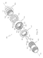
- FIG. 3 is an exploded view of a ball ramp torque limiter that may be employed in the transcowl actuation system shown in FIG. 2;
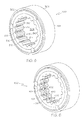
- FIGs. 4, 5, and 6 are isometric views of a spline suitable for use in conjunction with torque limiter shown in FIG. 3 in accordance with first, second, and third embodiments of the present invention, respectively.
- FIG. 1 is an isometric cut-away view of a jet engine fan case 100 incorporating a cascade-type thrust reverser system 102 that may be deployed on an aircraft (not shown).
- Thrust reverser 102 comprises a plurality of cascade vanes 104 disposed on a circumferential portion of case 100.
- Cascade vanes 104 are illustrated as exposed in FIG. 1; however, vanes 104 are typically covered by a plurality (e.g., two) of translating sleeves or cowls referred to as transcowls and discussed below in conjunction with FIG. 2.
- the transcowls are mechanically to a series of blocker doors 106, which are moveable between a stowed and a deployed position, In the stowed position (illustrated in FIG.
- blocker doors 106 are oriented parallel to a bypass air flow path 108.
- thrust reverser system 102 When thrust reverser system 102 is activated, blocker doors 106 rotate into a deployed position thereby blocking bypass air flow path 108 and the transcowls translate aft. This causes cascade vanes 104 to be exposed and the bypass air flow to be redirected out of cascade vanes 104 in a generally forward direction thereby creating a reverse thrust, which helps to decelerate the aircraft upon landing.
- FIG. 2 is a functional view of a portion of a transcowl actuation system 110 suitable for use in conjunction with thrust reverser system 102 (FIG. 1).
- Transcowl actuation system 110 comprises a transcowl 112 fixedly coupled to a plurality (e.g., three) of ball ballscrew actuators (i.e., an upper actuator 114, a center actuator 116, and a lower actuator 118).
- a motor 120 including a brake 122 (e.g., torque activated brake assembly), is directly coupled to center actuator 116 by way of a drive mechanism 124 (e.g., a flexible drive shaft).
- a brake 122 e.g., torque activated brake assembly
- Center actuator 116 is coupled, in turn, to upper actuator 114 and lower actuator 118 by way of flexible shafts 126 and 128, respectively.
- Drive shafts 124, 126, and 128 ensure that actuators 114, 116, and 118, and thus all points on transcowl 112, move in a substantially synchronized manner.
- Motor 120 commands actuator 116, and thus actuators 114 and 118, to extend or retract their respective shafts to move transcowl 112 between a deployed position (vanes 104 exposed as shown in FIG. 1) and a stowed position (vanes 104 covered).
- center ball ballscrew actuator 116 may include a manual drive unit (MDU) 130, which allows the manual actuation of transcowl 112 during routine maintenance.
- MDU manual drive unit
- a torque limiter (e.g., a ball ramp torque limiter) may be incorporated into MDU 130 (or into any one of actuators 114, 116, and 118).
- FIG. 3 provides an exploded view of ball ramp torque limiter 132 suitable for this use.
- Torque limiter l32 is configured for rotational movement about rotational axis 131 and comprises an input/drive shaft 134, a spring 136, a translating plate or spline 138, a set of torque-transferring ball bearings 169, a non-translating plate 140, and an output shaft 142.
- a set of bearings 151 is disposed about a segment of output shaft 142 and axially engages non-translating plate 140.
- Drive shaft 134 includes an annular collar 144 and a splined or toothed end portion having a plurality of outer teeth 146 circumferentially disposed there round.
- output shaft 142 includes an annular collar 148 and a splined or toothed medial portion having a plurality of outer teeth 150 circumferentially disposed there round.
- Output shaft 142 includes a longitudinal post 156 that may be received by a cylindrical cavity 158 provided in the first end portion of drive shaft 134.
- Spring 136, spline 138, and non-translating plate 140 each have an aperture therethrough for receiving post 146, and spline 138 and plate 140 each have a plurality of inwardly-protruding teeth 152 and 154, respectively.
- non-translating plate 140 is placed in an abutting relationship with bearings 151, and inner teeth 154 engage outer teeth 150.
- Spline 138 and spring 136 are also threaded over post 156 such that a first end of spring 136 abuts collar 144 and a second, opposite end of spring 136 abuts spline 138.
- spring 136, translating spline 138, and non-translating plate 140 are confined between collar 144 of drive shaft 134 and collar 148 of output shaft 142, and spline 138 is biased toward plate 140 by spring 136.
- a plurality (e.g., three) of conical pockets 166 is provided in the first end section of spline 138 adjacent non-translating plate 140.
- Three identical conical pockets are also provided in non-translating plate 140 (not shown).
- a circular track 168 transects each of pockets 166.
- pockets 166 cooperate with the pockets in non-translating plate 140 to form a series of ramped cavities.
- a torque-transferring ball bearing 169 is disposed within each of these cavities. Ball bearings 169 generally serve to transfer torque from spline 138 to non-translating plate 140.
- Ball bearings 169 remain in their respective cavities when the shear force exerted on bearings 169 is less than the force exerted on translating spline 138 by spring 136.
- the shear force exerted on ball bearings 169 overcomes the spring force exerted on spline 138.
- Ball bearings 169 roll up the ramped sides of the cavities and enter track 168.
- Ball bearings 169 consequently force translating spline 138 to separate from non-translating plate 140, move toward collar 144 of drive shaft 134, and compress spring 136.
- Drive shaft 134 is thus permitted to rotate independently of output shaft 142, and bearings 169 do not transfer torque from drive shaft 134 to output shaft 142. In this way, torque limiter 132 limits the torque transferred to output shaft 142 when the torque at shaft 134 exceeds the predetermined threshold value.
- the spline coupling employed by torque limiter 132 (and other such rotary couplings) generally requires lubrication to ensure optimal functioning. If the spline coupling of torque limiter 132 is not properly lubricated, an increase in the coefficient of friction may alter the torque at which spline 138 and plate 140 separate, which may ultimately result in damage to transcowl actuation system 110 (FIG. 2). Specifically, proper lubrication must be maintained along the inner annular portion of translating spline 138, which engages teeth 146 of shaft 134.
- translating spline 138 may rotate at a relatively high rotational frequency (e.g., 10,000 revolutions per minute), lubricant applied to the inner portion of spline 138 may be expelled by centrifugal force. Additionally, if grease is used as the lubricant, the centrifugal force may separate the base oil from the thickener of the grease.
- spline 138 may be replaced with a rotatable body or spline having one or more lubricant retaining features to minimize the loss of lubrication and to facilitate the dispersal of lubrication during rotation as described in more detail below.
- FIG. 4 illustrates a translating plate or spline 200 having a lubricant retaining feature in accordance with a first embodiment of the present invention.
- Spline 200 e.g., carbonized steel
- Sections 202, 204, and 206 cooperate to form a substantially tubular (e.g., annular) body comprising an outer annular portion and an inner annular portion 210 having an aperture 208 therethrough.
- Inner annular portion 210 includes a plurality of inwardly-protruding teeth 212 circumferentially spaced around portion 210.
- Teeth 212 are configured to matingly engage the teeth of a rotatable body disposed within aperture 208 (e.g., teeth 150 of output shaft 142) as described above.
- Inner annular portion 210 further includes a plurality of root structures 214 that are interspersed with teeth 212. Root structures 214 may be conveniently described as exposed portions of an inner annular surface from which teeth 212 protrude and in which the lubricant retaining feature or features (described below) are disposed.
- spline 200 may include a plurality of hemi-spherical pockets 216 in end section 202 for receiving axial load ball bearings in the manner described above.
- Spline 200 is provided with a slot or groove 218 around an inner circumference of medial section 206.
- groove 218 is provided within inner annular surface 210, and transects (e.g., bisects) each of teeth 212.
- Groove 218 provides spline 200 with a reservoir capable of retaining a significant volume of lubricant (e.g., grease) during rotational movement. During rapid rotation of body 200, centrifugal force will direct lubricant into groove 218 wherein the lubricant will be retained by the inner walls of groove 218.
- lubricant e.g., grease
- groove 218 may facilitate the dispersal of lubricant about inner annular surface 210 by, for example, facilitating the flow of lubricant between adjacent pairs of root structures 214. Considering this, it should be appreciated that spline 200 will retain lubrication longer than will a conventional spline.
- FIG. 5 illustrates a spline 300 in accordance with a second embodiment of the present invention.
- Spline 300 is similar to spline 200 (FIG. 4); i.e., spline 300 includes a first end section 302, a second end section 304, and a medial section 306 disposed between sections 302 and 304. Sections 302, 304, and 306 cooperate to form an annular body having an aperture 308 therethrough and an inner annular portion 310, which comprises a plurality of alternating teeth 312 and root structures 314.
- spline 300 includes a plurality of radially transverse slots 316 between each of teeth 312.
- each slot 316 is disposed within the middle of a different one of root structures 314, and is substantially parallel to the axis about which spline 300 rotates. Slots 316 may assume a variety of shapes and dimensions. Slots 316 should not, however, extend entirely through end section 302 or end section 304 as this would allow lubricant to escape from inner annular portion 310 during the rotation of spline 300.
- radially transverse slots 316 of spline 300 will function to provide lubricant retention in substantially the same way as does circumferential groove 218 of spline 200 (FIG. 4). This not withstanding, slots 316 will not readily facilitate the dispersal of lubricant along the inner annular portion 310 of spline 300.
- the inventive spline may be provided a combination of lubricant retaining features.
- spline 400 which is shown in FIG. 6, is provided with a circumferential groove 402, a plurality of radially transverse slots 404, and a plurality of inner teeth 406.
- Groove 402 extends through (e.g., bisects) each of teeth 406 and transects (e.g., bisects) each of radially transverse slots 404. Groove 402 permits fluid communication between adjacent ones of slots 404 thereby promoting the uniform dispersal of lubrication along the inner annular surface of spline 400. As an additional advantage, the collective volume of groove 402 and slots 404 is significantly greater than that of groove 402 or radially transverse slots 404 alone thereby improving the lubricant retaining ability of spline 400.
- the lubricant retaining features described above may be machined into the spline after manufacture.
- the structure and dimensions of the lubricant retaining features will vary with the dimensions of the spline and the intended application. For example, if the spline is to be utilized for an application requiring maximum tooth strength, a circumferential groove may be preferable over a plurality of radially transverse slots disposed in the root structures. In general, however, it will be preferable to utilize a combination of lubricant retaining features (e.g., a circumferential groove with a plurality of radially transverse slots) to maximize the lubricant retaining ability of the spline.
- a combination of lubricant retaining features e.g., a circumferential groove with a plurality of radially transverse slots
- a rotary coupling employing a rotatable body (e.g., a spline) having one or more features that facilitate the retention and dispersal of lubricant has been provided. While at least one exemplary embodiment has been presented in the foregoing detailed description, it should be appreciated that a vast number of variations exist. It should also be appreciated that the exemplary embodiment or exemplary embodiments are only examples, and are not intended to limit the scope, applicability, or configuration of the invention in any way. Rather, the foregoing detailed description will provide those skilled in the art with a convenient road map for implementing the exemplary embodiment or exemplary embodiments. It should be understood that various changes can be made in the function and arrangement of elements without departing from the scope of the invention as set forth in the appended claims and the legal equivalents thereof.
Landscapes
- Engineering & Computer Science (AREA)
- General Engineering & Computer Science (AREA)
- Mechanical Engineering (AREA)
- One-Way And Automatic Clutches, And Combinations Of Different Clutches (AREA)
Abstract
Description
- The present invention relates to a torque limiter employed in an aircraft's transcowl actuation system and, more particularly, to a spline including an inner annular portion having one or more lubricant retaining features.
- In spline couplings and other such rotary couplings (e.g., epicycle gear couplings), a drive shaft may be received within a cavity provided through annular plate or spine. In certain systems, the spline may translate with respect to the drive shaft. For example, in a ball ramp torque limiter, the spline may comprise a translating plate having a plurality of inner teeth that engage outer teeth provided about the drive shaft. The spline is spring biased toward a second, non-translating plate that is coupled to an output shaft. When the torque at the drive shaft is below a predetermined threshold, the spline and the non-translating plate abutting engage. The spline and the non-translating plate each include a series of conical pockets therein. Each conical pocket provided on the spline cooperates with a pocket on the non-translating plate to form a ramped cavity. An axial load ball bearing resides in each ramped cavity, and generally serves to transfer torque from the spline to the non-translating plate. As the torque limiter rotates, a shear force is exerted on the ball bearings. When the torque at the drive shaft exceeds the predetermined torque threshold (the activation torque), the shear force exerted on the ball bearings exceeds the spring force exerted on the spline. As a result, the ball bearings roll up the cavities' ramped sides and leave their respective cavities. This causes the spline and the non-translating plate to separate thereby permitting the drive shaft to rotate independently of the output shaft. The transfer of torque to the output shaft is thus limited when the torque at the drive shaft exceeds the predetermined threshold.
- Rotary couplings typically require lubrication to ensure optimal functioning. In the case of a spline coupling utilized in a ball ramp torque limiter, a lack of lubrication may lead to excessive friction and a consequent increase in the activation torque (i.e., the predetermined torque threshold at which the transfer of torque is interrupted). This increase in the activation torque may, in turn, result in damage to system components. Even after initial application, re-application of lubricant is often required as the lubricant may be expelled at high rotational frequencies by centrifugal forces. If grease is used as the lubricant, the centrifugal force may separate the base oil from the thickener of the grease. Accessing the rotary coupling typically involves a cumbersome process thereby making repeated manual applications of lubrication impractical. Consequently, various sub-systems have been developed that actively supply lubricant to rotary couplings; however, such sub-systems may be relatively complex and expensive to employ. In addition, such sub-systems add to the weight of the rotary coupling, which may be problematic if the rotary coupling is utilized in a system deployed on an aircraft (e.g., a torque limiter employed in a ballscrew actuator). Furthermore, active supply sub-systems may have difficulty conducting thicker lubricants (e.g., grease).
- Considering the above, it should be appreciated that it would be desirable to provide a rotary coupling employing a spline having one or more features that facilitate the retention of lubricant. It should also be appreciated that it would be advantageous if such lubricant retaining features also promoted the uniform dispersal of lubricant. Furthermore, other desirable features and characteristics of the present invention will become apparent from the subsequent detailed description of the invention and the appended claims, taken in conjunction with the accompanying drawings and this background of the invention.
- A torque limiter for use on an aircraft is provided. The torque limiter comprises a drive shaft, an output shaft having a toothed portion, and a spline coupled to the drive shaft and having an aperture therethrough for receiving the toothed portion. The spline is configured to disengage from the toothed portion when the torque at the drive shaft exceeds a predetermined threshold to limit the transfer of torque from the drive shaft to the output shaft. The spline comprises an outer annular portion and an inner annular portion configured to receive a lubricant. The inner annular portion comprises a plurality of circumferentially-spaced tooth structures and root structures. At least one of the root structures has at least one slot therein for receiving and retaining the lubricant.
- Furthermore, other desirable features and characteristics of the present invention will become apparent from the subsequent detailed description of the invention and the appended claims, taken in conjunction with the accompanying drawings and this background of the invention.
- The preferred exemplary embodiment of the present invention will hereinafter be described in conjunction with the appended drawings, where like designations denote like elements, and:
- FIG. 1 is an isometric cutaway view of a conventional jet engine fan case;
- FIG. 2 is a functional view of a transcowl actuation system suitable for use in conjunction with the fan case shown in FIG. 1;
- FIG. 3 is an exploded view of a ball ramp torque limiter that may be employed in the transcowl actuation system shown in FIG. 2; and
- FIGs. 4, 5, and 6 are isometric views of a spline suitable for use in conjunction with torque limiter shown in FIG. 3 in accordance with first, second, and third embodiments of the present invention, respectively.
- The following detailed description is merely exemplary in nature and is not intended to limit the invention or the application and uses of the invention. Furthermore, there is no intention to be bound by any expressed or implied theory presented in the preceding technical field, background, brief summary or the following detailed description.
- FIG. 1 is an isometric cut-away view of a jet
engine fan case 100 incorporating a cascade-typethrust reverser system 102 that may be deployed on an aircraft (not shown).Thrust reverser 102 comprises a plurality ofcascade vanes 104 disposed on a circumferential portion ofcase 100.Cascade vanes 104 are illustrated as exposed in FIG. 1; however,vanes 104 are typically covered by a plurality (e.g., two) of translating sleeves or cowls referred to as transcowls and discussed below in conjunction with FIG. 2. The transcowls are mechanically to a series ofblocker doors 106, which are moveable between a stowed and a deployed position, In the stowed position (illustrated in FIG. 1),blocker doors 106 are oriented parallel to a bypass air flow path 108. Whenthrust reverser system 102 is activated,blocker doors 106 rotate into a deployed position thereby blocking bypass air flow path 108 and the transcowls translate aft. This causescascade vanes 104 to be exposed and the bypass air flow to be redirected out ofcascade vanes 104 in a generally forward direction thereby creating a reverse thrust, which helps to decelerate the aircraft upon landing. - FIG. 2 is a functional view of a portion of a
transcowl actuation system 110 suitable for use in conjunction with thrust reverser system 102 (FIG. 1).Transcowl actuation system 110 comprises atranscowl 112 fixedly coupled to a plurality (e.g., three) of ball ballscrew actuators (i.e., anupper actuator 114, acenter actuator 116, and a lower actuator 118). Amotor 120, including a brake 122 (e.g., torque activated brake assembly), is directly coupled tocenter actuator 116 by way of a drive mechanism 124 (e.g., a flexible drive shaft).Center actuator 116 is coupled, in turn, toupper actuator 114 andlower actuator 118 by way offlexible shafts Drive shafts actuators transcowl 112, move in a substantially synchronized manner.Motor 120commands actuator 116, and thusactuators transcowl 112 between a deployed position (vanes 104 exposed as shown in FIG. 1) and a stowed position (vanes 104 covered). If desired, centerball ballscrew actuator 116 may include a manual drive unit (MDU) 130, which allows the manual actuation oftranscowl 112 during routine maintenance. - To prevent physical damage to
transcowl 112, a torque limiter (e.g., a ball ramp torque limiter) may be incorporated into MDU 130 (or into any one ofactuators ramp torque limiter 132 suitable for this use. Torque limiter l32 is configured for rotational movement aboutrotational axis 131 and comprises an input/drive shaft 134, aspring 136, a translating plate orspline 138, a set of torque-transferringball bearings 169, anon-translating plate 140, and anoutput shaft 142. A set ofbearings 151 is disposed about a segment ofoutput shaft 142 and axially engagesnon-translating plate 140.Drive shaft 134 includes anannular collar 144 and a splined or toothed end portion having a plurality ofouter teeth 146 circumferentially disposed there round. Similarly,output shaft 142 includes anannular collar 148 and a splined or toothed medial portion having a plurality ofouter teeth 150 circumferentially disposed there round. -
Output shaft 142 includes alongitudinal post 156 that may be received by acylindrical cavity 158 provided in the first end portion ofdrive shaft 134.Spring 136,spline 138, andnon-translating plate 140 each have an aperture therethrough for receivingpost 146, andspline 138 andplate 140 each have a plurality of inwardly-protrudingteeth post 156,non-translating plate 140 is placed in an abutting relationship withbearings 151, andinner teeth 154 engageouter teeth 150.Spline 138 andspring 136 are also threaded overpost 156 such that a first end ofspring 136abuts collar 144 and a second, opposite end ofspring 136abuts spline 138. Thus, whentorque limiter 132 is assembled,spring 136, translatingspline 138, andnon-translating plate 140 are confined betweencollar 144 ofdrive shaft 134 andcollar 148 ofoutput shaft 142, andspline 138 is biased towardplate 140 byspring 136. - As can be seen in FIG. 3, a plurality (e.g., three) of
conical pockets 166 is provided in the first end section ofspline 138 adjacentnon-translating plate 140. Three identical conical pockets are also provided in non-translating plate 140 (not shown). Acircular track 168 transects each of pockets 166. When translatingspline 138 abuttingly engagesnon-translating plate 140, pockets 166 cooperate with the pockets innon-translating plate 140 to form a series of ramped cavities. A torque-transferringball bearing 169 is disposed within each of these cavities.Ball bearings 169 generally serve to transfer torque fromspline 138 tonon-translating plate 140. Astorque limiter 132 rotates, a shear force is exerted onball bearings 169.Ball bearings 169 remain in their respective cavities when the shear force exerted onbearings 169 is less than the force exerted on translatingspline 138 byspring 136. When the torque atdrive shaft 134 meets or exceeds the threshold value, however, the shear force exerted onball bearings 169 overcomes the spring force exerted onspline 138. As a result,ball bearings 169 roll up the ramped sides of the cavities and entertrack 168.Ball bearings 169 consequently force translatingspline 138 to separate fromnon-translating plate 140, move towardcollar 144 ofdrive shaft 134, and compressspring 136. Driveshaft 134 is thus permitted to rotate independently ofoutput shaft 142, andbearings 169 do not transfer torque fromdrive shaft 134 tooutput shaft 142. In this way,torque limiter 132 limits the torque transferred tooutput shaft 142 when the torque atshaft 134 exceeds the predetermined threshold value. - As previously mentioned, the spline coupling employed by torque limiter 132 (and other such rotary couplings) generally requires lubrication to ensure optimal functioning. If the spline coupling of
torque limiter 132 is not properly lubricated, an increase in the coefficient of friction may alter the torque at whichspline 138 andplate 140 separate, which may ultimately result in damage to transcowl actuation system 110 (FIG. 2). Specifically, proper lubrication must be maintained along the inner annular portion of translatingspline 138, which engagesteeth 146 ofshaft 134. However, as translatingspline 138 may rotate at a relatively high rotational frequency (e.g., 10,000 revolutions per minute), lubricant applied to the inner portion ofspline 138 may be expelled by centrifugal force. Additionally, if grease is used as the lubricant, the centrifugal force may separate the base oil from the thickener of the grease. In accordance with the present invention,spline 138 may be replaced with a rotatable body or spline having one or more lubricant retaining features to minimize the loss of lubrication and to facilitate the dispersal of lubrication during rotation as described in more detail below. - FIG. 4 illustrates a translating plate or
spline 200 having a lubricant retaining feature in accordance with a first embodiment of the present invention. Spline 200 (e.g., carbonized steel) comprises afirst end section 202, asecond end section 204 substantiallyopposite section 202, and amedial section 206intermediate sections Sections annular portion 210 having anaperture 208 therethrough. Innerannular portion 210 includes a plurality of inwardly-protrudingteeth 212 circumferentially spaced aroundportion 210.Teeth 212 are configured to matingly engage the teeth of a rotatable body disposed within aperture 208 (e.g.,teeth 150 of output shaft 142) as described above. Innerannular portion 210 further includes a plurality ofroot structures 214 that are interspersed withteeth 212.Root structures 214 may be conveniently described as exposed portions of an inner annular surface from whichteeth 212 protrude and in which the lubricant retaining feature or features (described below) are disposed. If employed in a ball ramp torque limiter, such as torque limiter 132 (FIG. 3),spline 200 may include a plurality of hemi-spherical pockets 216 inend section 202 for receiving axial load ball bearings in the manner described above. -
Spline 200 is provided with a slot or groove 218 around an inner circumference ofmedial section 206. In particular,groove 218 is provided within innerannular surface 210, and transects (e.g., bisects) each ofteeth 212.Groove 218 providesspline 200 with a reservoir capable of retaining a significant volume of lubricant (e.g., grease) during rotational movement. During rapid rotation ofbody 200, centrifugal force will direct lubricant intogroove 218 wherein the lubricant will be retained by the inner walls ofgroove 218. Additionally, groove 218 may facilitate the dispersal of lubricant about innerannular surface 210 by, for example, facilitating the flow of lubricant between adjacent pairs ofroot structures 214. Considering this, it should be appreciated thatspline 200 will retain lubrication longer than will a conventional spline. - FIG. 5 illustrates a
spline 300 in accordance with a second embodiment of the present invention.Spline 300 is similar to spline 200 (FIG. 4); i.e.,spline 300 includes afirst end section 302, asecond end section 304, and amedial section 306 disposed betweensections Sections aperture 308 therethrough and an inner annular portion 310, which comprises a plurality of alternatingteeth 312 androot structures 314. Unlikespline 200, however,spline 300 includes a plurality of radiallytransverse slots 316 between each ofteeth 312. Preferably, eachslot 316 is disposed within the middle of a different one ofroot structures 314, and is substantially parallel to the axis about which spline 300 rotates.Slots 316 may assume a variety of shapes and dimensions.Slots 316 should not, however, extend entirely throughend section 302 orend section 304 as this would allow lubricant to escape from inner annular portion 310 during the rotation ofspline 300. - It should be apparent that radially
transverse slots 316 of spline 300 (FIG. 5) will function to provide lubricant retention in substantially the same way as does circumferential groove 218 of spline 200 (FIG. 4). This not withstanding,slots 316 will not readily facilitate the dispersal of lubricant along the inner annular portion 310 ofspline 300. To facilitate the dispersal of lubrication, the inventive spline may be provided a combination of lubricant retaining features. As an example,spline 400, which is shown in FIG. 6, is provided with acircumferential groove 402, a plurality of radiallytransverse slots 404, and a plurality ofinner teeth 406.Groove 402 extends through (e.g., bisects) each ofteeth 406 and transects (e.g., bisects) each of radiallytransverse slots 404. Groove 402 permits fluid communication between adjacent ones ofslots 404 thereby promoting the uniform dispersal of lubrication along the inner annular surface ofspline 400. As an additional advantage, the collective volume ofgroove 402 andslots 404 is significantly greater than that ofgroove 402 or radiallytransverse slots 404 alone thereby improving the lubricant retaining ability ofspline 400. - The lubricant retaining features described above may be machined into the spline after manufacture. The structure and dimensions of the lubricant retaining features will vary with the dimensions of the spline and the intended application. For example, if the spline is to be utilized for an application requiring maximum tooth strength, a circumferential groove may be preferable over a plurality of radially transverse slots disposed in the root structures. In general, however, it will be preferable to utilize a combination of lubricant retaining features (e.g., a circumferential groove with a plurality of radially transverse slots) to maximize the lubricant retaining ability of the spline. Though discussed above in conjunction with a spline coupling utilized by a ball ramp torque limiter, it should be understood that the inventive lubricant retaining features are equally applicable to other rotary couplings (e.g., epicycle gear couplings) and spline couplings utilized in other contexts.
- In view of the above, it should be appreciated that a rotary coupling employing a rotatable body (e.g., a spline) having one or more features that facilitate the retention and dispersal of lubricant has been provided. While at least one exemplary embodiment has been presented in the foregoing detailed description, it should be appreciated that a vast number of variations exist. It should also be appreciated that the exemplary embodiment or exemplary embodiments are only examples, and are not intended to limit the scope, applicability, or configuration of the invention in any way. Rather, the foregoing detailed description will provide those skilled in the art with a convenient road map for implementing the exemplary embodiment or exemplary embodiments. It should be understood that various changes can be made in the function and arrangement of elements without departing from the scope of the invention as set forth in the appended claims and the legal equivalents thereof.
Claims (10)
- A torque limiter (132) for use on an aircraft, comprising:a drive shaft (134) having a toothed outer portion;an output shaft (142); anda spline (138) having an aperture (208) therethrough that receives said toothed outer portion, said spline (138) configured to normally rotationally couple said drive shaft (134) to said output shaft (142) and to rotationally disengage from said output shaft (142) when the torque at said drive shaft (134) exceeds a predetermined torque threshold, said spline (138) comprising:an outer annular portion; andan inner annular portion (210) configured to receive a lubricant, said inner annular portion comprising a plurality of circumferentially-spaced tooth structures (212, 312, 406) and root structures (214, 314), at least one of said root structures (214, 314) having at least one slot (316, 404) therein for receiving and retaining the lubricant.
- A torque limiter (132) according to claim 1 wherein said at least one slot (3l6, 404) comprises a plurality of radially transverse slots (316, 404).
- A torque limiter (132) according to claim 2 wherein each of said plurality of radially transverse slots (316, 404) is disposed within a different one of said root structures (214, 314).
- A torque limiter (132) according to claim 2 further comprising a groove (218, 402) in said inner annular portion (210) transecting at least one of said plurality of radially transverse slots (316, 404).
- A torque limiter (132) according to claim 1 wherein said at least one slot (316, 404) comprises a groove (218, 402) in said inner annular portion (210) and through at least one of said tooth structures (212, 312, 406).
- A torque limiter (132) according to claim 5 wherein said groove (218, 402) extends around a circumference of said inner annular portion (210).
- A spline (200, 300, 400) having a cavity therein for receiving a rotatable shaft (134) having a plurality of outer teeth (146) and for receiving a lubricant, the spline (200, 300, 400) comprising:an inner annular surface (210) proximate the cavity;a plurality of inner teeth (212, 312, 406) extending from said inner annular surface (210) into the cavity and configured to engage the plurality of outer teeth (146); anda plurality of radially transverse slots (316, 404) in said inner annular surface (210) for receiving and retaining the lubricant.
- A spline (200, 300, 400) according to claim 7 wherein each of said plurality of radially transverse slots (316, 404) is substantially disposed between a different pair of adjacent ones of said plurality of inner teeth (212, 312, 406).
- A spline (200, 300, 400) according to claim 8 further comprising a groove (218, 402) around at least a portion of a circumference of said inner annular surface (210).
- A spline (200, 300, 400) according to claim 9 wherein said groove (218, 402) transects at least two radially transverse slots (316, 404) in said plurality of radially transverse slots (316, 404) so as to provide fluid communication there between.
Applications Claiming Priority (1)
| Application Number | Priority Date | Filing Date | Title |
|---|---|---|---|
| US11/414,645 US7491127B2 (en) | 2006-04-27 | 2006-04-27 | Spline with lubricant retention feature for use in torque limiter |
Publications (1)
| Publication Number | Publication Date |
|---|---|
| EP1850022A1 true EP1850022A1 (en) | 2007-10-31 |
Family
ID=38308606
Family Applications (1)
| Application Number | Title | Priority Date | Filing Date |
|---|---|---|---|
| EP07106990A Withdrawn EP1850022A1 (en) | 2006-04-27 | 2007-04-26 | Spline with lubricant retention feature for use in torque limiter |
Country Status (2)
| Country | Link |
|---|---|
| US (1) | US7491127B2 (en) |
| EP (1) | EP1850022A1 (en) |
Cited By (1)
| Publication number | Priority date | Publication date | Assignee | Title |
|---|---|---|---|---|
| FR3022294A1 (en) * | 2014-06-12 | 2015-12-18 | Peugeot Citroen Automobiles Sa | MOTOR-RECEIVER GROUP WITH LUBRICATED COUPLING |
Families Citing this family (8)
| Publication number | Priority date | Publication date | Assignee | Title |
|---|---|---|---|---|
| US7839053B2 (en) * | 2007-03-28 | 2010-11-23 | Hoya Corporation | One-way rotational transfer mechanism, and ultrasonic rotary drive device incorporating one-way rotational transfer mechanism |
| US9677662B2 (en) * | 2007-12-20 | 2017-06-13 | Rolls-Royce Corporation | Dual splined shaft |
| CN102414457A (en) * | 2009-05-08 | 2012-04-11 | 纳博特斯克株式会社 | Key connecting mechanism |
| US8678937B2 (en) * | 2009-12-01 | 2014-03-25 | Rolls-Royce Corporation | Shaft coupling |
| JP5750296B2 (en) * | 2011-04-15 | 2015-07-15 | アルパイン株式会社 | In-vehicle display device |
| AU2012203111B2 (en) * | 2011-05-26 | 2015-12-10 | Sandvik Intellectual Property Ab | Improvements to RC hammer bit lubrication |
| US10731742B2 (en) * | 2017-12-08 | 2020-08-04 | Torq-Masters Industries, Inc | Axle coupler with ring recess |
| USD1111054S1 (en) | 2023-05-27 | 2026-02-03 | Torq-Masters Industries, Inc. | Locker set for a differential |
Citations (6)
| Publication number | Priority date | Publication date | Assignee | Title |
|---|---|---|---|---|
| US1973702A (en) * | 1933-03-31 | 1934-09-18 | Frank V Cooke | Slip joint |
| US3203201A (en) * | 1963-02-25 | 1965-08-31 | Hyster Co | Slip joint for a mechanical drive |
| US4153260A (en) * | 1978-06-02 | 1979-05-08 | Dana Corporation | Slip spline seal assembly |
| FR2432380A1 (en) * | 1978-08-04 | 1980-02-29 | Nacam | Injection moulded coatings for sliding rotary shaft gears - to obtain close tolerance profiles without extensive machining of gears or coatings |
| US5503494A (en) * | 1993-07-22 | 1996-04-02 | Honda Giken Kogyo Kabushiki Kaisha | Spline-coupling structure |
| DE19717290A1 (en) * | 1997-04-24 | 1998-10-29 | Claas Usines France | Torque measuring system, transmitting by line drive protected by overload, for coupling machines |
Family Cites Families (17)
| Publication number | Priority date | Publication date | Assignee | Title |
|---|---|---|---|---|
| US1586990A (en) * | 1924-04-22 | 1926-06-01 | Henry P Harrison | Spline shaft |
| US1756335A (en) * | 1924-06-19 | 1930-04-29 | Auto Research Corp | Trunnion joint and the lubrication thereof and of associated parts |
| US1973708A (en) * | 1932-10-08 | 1934-09-18 | Heller Hugo | Cleaning device |
| DE1273289B (en) * | 1965-03-04 | 1973-11-15 | ||
| US3455122A (en) * | 1966-08-19 | 1969-07-15 | Babcock & Wilcox Co | Precision spline |
| CH469208A (en) * | 1967-10-21 | 1969-02-28 | Stoeckicht Alexander W | Tooth coupling |
| US3889489A (en) * | 1974-08-23 | 1975-06-17 | Gen Motors Corp | Lubricated spline coupling |
| JPS61180063A (en) * | 1984-09-12 | 1986-08-12 | Toshiba Mach Co Ltd | Statical pressure worm rack |
| JPS61286593A (en) * | 1985-06-07 | 1986-12-17 | マネスマン レクスロ−ト ゲゼルシヤフトミツト ベシユレンクタ− ハフツング | Gearing |
| US4913671A (en) * | 1988-04-07 | 1990-04-03 | Brunswick Corporation | Marine drive with lubricated output coupler |
| DE4223374C2 (en) * | 1992-07-16 | 1994-09-15 | Viscodrive Gmbh | Differential gear |
| US5624344A (en) * | 1995-05-01 | 1997-04-29 | Zexel Torsen Inc. | Lubrication system for a parallel-axis differential |
| JP3017416B2 (en) * | 1995-06-14 | 2000-03-06 | エヌティエヌ株式会社 | Torque-sensitive rotation control device |
| JP3390124B2 (en) * | 1997-02-19 | 2003-03-24 | アイダエンジニアリング株式会社 | screw |
| US5901817A (en) * | 1997-04-18 | 1999-05-11 | The Boeing Company | Torque limiter with trip indicator |
| US6666307B1 (en) * | 2002-08-05 | 2003-12-23 | Honeywell International, Inc. | Thrust reverser system with a pass-through torque activated brake |
| US6786315B1 (en) * | 2003-03-28 | 2004-09-07 | Honeywell International, Inc. | Thrust reverser system with sequential torque decoupler |
-
2006
- 2006-04-27 US US11/414,645 patent/US7491127B2/en not_active Expired - Fee Related
-
2007
- 2007-04-26 EP EP07106990A patent/EP1850022A1/en not_active Withdrawn
Patent Citations (6)
| Publication number | Priority date | Publication date | Assignee | Title |
|---|---|---|---|---|
| US1973702A (en) * | 1933-03-31 | 1934-09-18 | Frank V Cooke | Slip joint |
| US3203201A (en) * | 1963-02-25 | 1965-08-31 | Hyster Co | Slip joint for a mechanical drive |
| US4153260A (en) * | 1978-06-02 | 1979-05-08 | Dana Corporation | Slip spline seal assembly |
| FR2432380A1 (en) * | 1978-08-04 | 1980-02-29 | Nacam | Injection moulded coatings for sliding rotary shaft gears - to obtain close tolerance profiles without extensive machining of gears or coatings |
| US5503494A (en) * | 1993-07-22 | 1996-04-02 | Honda Giken Kogyo Kabushiki Kaisha | Spline-coupling structure |
| DE19717290A1 (en) * | 1997-04-24 | 1998-10-29 | Claas Usines France | Torque measuring system, transmitting by line drive protected by overload, for coupling machines |
Cited By (1)
| Publication number | Priority date | Publication date | Assignee | Title |
|---|---|---|---|---|
| FR3022294A1 (en) * | 2014-06-12 | 2015-12-18 | Peugeot Citroen Automobiles Sa | MOTOR-RECEIVER GROUP WITH LUBRICATED COUPLING |
Also Published As
| Publication number | Publication date |
|---|---|
| US20070254743A1 (en) | 2007-11-01 |
| US7491127B2 (en) | 2009-02-17 |
Similar Documents
| Publication | Publication Date | Title |
|---|---|---|
| US5605071A (en) | Enveloped worm gear clutch wedgelock responsive to reaction force | |
| DE69501027T2 (en) | Synchromechanism for gears | |
| DE60318721T2 (en) | CUTTING DISC FOR CONTINUOUS CURRENT GENERATOR WITH BLANK WIRE SPRING AND GREASE LUBRICATION | |
| US7491127B2 (en) | Spline with lubricant retention feature for use in torque limiter | |
| CN110621913A (en) | Separable speed reducer device | |
| DE102012205764A1 (en) | torsional vibration damper | |
| DE3544392A1 (en) | AERODYNAMIC SLIDING BEARING | |
| DE102014217853A1 (en) | Dual mass flywheel with torque limiter and centrifugal pendulum | |
| US10364020B2 (en) | Pitch change mechanism for a bladed rotor | |
| US9828089B2 (en) | Rotor drive systems for rotorcraft | |
| CA2890718C (en) | Torque limiter | |
| DE102008031010A1 (en) | Two-channel multi-function torque converter | |
| EP1813831B1 (en) | Cooling medium distribution device | |
| WO2015081953A1 (en) | Device for transmitting torque | |
| CN109386385B (en) | Decoupler assembly for an engine starter | |
| DE102015226220A1 (en) | Double coupling | |
| DE112018005564T5 (en) | INTERFACE MODULE FOR A DRIVELINE | |
| WO2014139522A1 (en) | Clutch arrangement for a vehicle and method for operating a vehicle | |
| DE102019001957C5 (en) | Hybrid drive system | |
| EP2851290B1 (en) | Propeller pitchlock system with a rotating interface | |
| DE102015213731A1 (en) | Connecting arrangement comprising two shafts | |
| WO2016150439A1 (en) | Torque transmission device | |
| DE102012202456B4 (en) | axial adjusting | |
| DE102014214297A1 (en) | clutch assembly | |
| EP3473879B1 (en) | A synchronizing ring |
Legal Events
| Date | Code | Title | Description |
|---|---|---|---|
| PUAI | Public reference made under article 153(3) epc to a published international application that has entered the european phase |
Free format text: ORIGINAL CODE: 0009012 |
|
| AK | Designated contracting states |
Kind code of ref document: A1 Designated state(s): AT BE BG CH CY CZ DE DK EE ES FI FR GB GR HU IE IS IT LI LT LU LV MC MT NL PL PT RO SE SI SK TR |
|
| AX | Request for extension of the european patent |
Extension state: AL BA HR MK YU |
|
| 17P | Request for examination filed |
Effective date: 20080415 |
|
| 17Q | First examination report despatched |
Effective date: 20080516 |
|
| AKX | Designation fees paid |
Designated state(s): DE FR GB |
|
| GRAP | Despatch of communication of intention to grant a patent |
Free format text: ORIGINAL CODE: EPIDOSNIGR1 |
|
| STAA | Information on the status of an ep patent application or granted ep patent |
Free format text: STATUS: THE APPLICATION IS DEEMED TO BE WITHDRAWN |
|
| 18D | Application deemed to be withdrawn |
Effective date: 20100616 |