EP1850021A1 - Rolling bearing - Google Patents
Rolling bearing Download PDFInfo
- Publication number
- EP1850021A1 EP1850021A1 EP06713765A EP06713765A EP1850021A1 EP 1850021 A1 EP1850021 A1 EP 1850021A1 EP 06713765 A EP06713765 A EP 06713765A EP 06713765 A EP06713765 A EP 06713765A EP 1850021 A1 EP1850021 A1 EP 1850021A1
- Authority
- EP
- European Patent Office
- Prior art keywords
- outer ring
- bearing
- rolling bearing
- insulation film
- rolling
- Prior art date
- Legal status (The legal status is an assumption and is not a legal conclusion. Google has not performed a legal analysis and makes no representation as to the accuracy of the status listed.)
- Withdrawn
Links
Images




Classifications
-
- F—MECHANICAL ENGINEERING; LIGHTING; HEATING; WEAPONS; BLASTING
- F16—ENGINEERING ELEMENTS AND UNITS; GENERAL MEASURES FOR PRODUCING AND MAINTAINING EFFECTIVE FUNCTIONING OF MACHINES OR INSTALLATIONS; THERMAL INSULATION IN GENERAL
- F16C—SHAFTS; FLEXIBLE SHAFTS; ELEMENTS OR CRANKSHAFT MECHANISMS; ROTARY BODIES OTHER THAN GEARING ELEMENTS; BEARINGS
- F16C35/00—Rigid support of bearing units; Housings, e.g. caps, covers
- F16C35/04—Rigid support of bearing units; Housings, e.g. caps, covers in the case of ball or roller bearings
- F16C35/06—Mounting or dismounting of ball or roller bearings; Fixing them onto shaft or in housing
- F16C35/067—Fixing them in a housing
-
- F—MECHANICAL ENGINEERING; LIGHTING; HEATING; WEAPONS; BLASTING
- F16—ENGINEERING ELEMENTS AND UNITS; GENERAL MEASURES FOR PRODUCING AND MAINTAINING EFFECTIVE FUNCTIONING OF MACHINES OR INSTALLATIONS; THERMAL INSULATION IN GENERAL
- F16C—SHAFTS; FLEXIBLE SHAFTS; ELEMENTS OR CRANKSHAFT MECHANISMS; ROTARY BODIES OTHER THAN GEARING ELEMENTS; BEARINGS
- F16C33/00—Parts of bearings; Special methods for making bearings or parts thereof
- F16C33/30—Parts of ball or roller bearings
- F16C33/58—Raceways; Race rings
- F16C33/583—Details of specific parts of races
- F16C33/586—Details of specific parts of races outside the space between the races, e.g. end faces or bore of inner ring
-
- F—MECHANICAL ENGINEERING; LIGHTING; HEATING; WEAPONS; BLASTING
- F16—ENGINEERING ELEMENTS AND UNITS; GENERAL MEASURES FOR PRODUCING AND MAINTAINING EFFECTIVE FUNCTIONING OF MACHINES OR INSTALLATIONS; THERMAL INSULATION IN GENERAL
- F16C—SHAFTS; FLEXIBLE SHAFTS; ELEMENTS OR CRANKSHAFT MECHANISMS; ROTARY BODIES OTHER THAN GEARING ELEMENTS; BEARINGS
- F16C33/00—Parts of bearings; Special methods for making bearings or parts thereof
- F16C33/30—Parts of ball or roller bearings
- F16C33/58—Raceways; Race rings
- F16C33/64—Special methods of manufacture
-
- F—MECHANICAL ENGINEERING; LIGHTING; HEATING; WEAPONS; BLASTING
- F16—ENGINEERING ELEMENTS AND UNITS; GENERAL MEASURES FOR PRODUCING AND MAINTAINING EFFECTIVE FUNCTIONING OF MACHINES OR INSTALLATIONS; THERMAL INSULATION IN GENERAL
- F16C—SHAFTS; FLEXIBLE SHAFTS; ELEMENTS OR CRANKSHAFT MECHANISMS; ROTARY BODIES OTHER THAN GEARING ELEMENTS; BEARINGS
- F16C19/00—Bearings with rolling contact, for exclusively rotary movement
- F16C19/02—Bearings with rolling contact, for exclusively rotary movement with bearing balls essentially of the same size in one or more circular rows
- F16C19/14—Bearings with rolling contact, for exclusively rotary movement with bearing balls essentially of the same size in one or more circular rows for both radial and axial load
- F16C19/16—Bearings with rolling contact, for exclusively rotary movement with bearing balls essentially of the same size in one or more circular rows for both radial and axial load with a single row of balls
- F16C19/163—Bearings with rolling contact, for exclusively rotary movement with bearing balls essentially of the same size in one or more circular rows for both radial and axial load with a single row of balls with angular contact
- F16C19/166—Four-point-contact ball bearings
-
- F—MECHANICAL ENGINEERING; LIGHTING; HEATING; WEAPONS; BLASTING
- F16—ENGINEERING ELEMENTS AND UNITS; GENERAL MEASURES FOR PRODUCING AND MAINTAINING EFFECTIVE FUNCTIONING OF MACHINES OR INSTALLATIONS; THERMAL INSULATION IN GENERAL
- F16C—SHAFTS; FLEXIBLE SHAFTS; ELEMENTS OR CRANKSHAFT MECHANISMS; ROTARY BODIES OTHER THAN GEARING ELEMENTS; BEARINGS
- F16C2226/00—Joining parts; Fastening; Assembling or mounting parts
- F16C2226/50—Positive connections
-
- F—MECHANICAL ENGINEERING; LIGHTING; HEATING; WEAPONS; BLASTING
- F16—ENGINEERING ELEMENTS AND UNITS; GENERAL MEASURES FOR PRODUCING AND MAINTAINING EFFECTIVE FUNCTIONING OF MACHINES OR INSTALLATIONS; THERMAL INSULATION IN GENERAL
- F16C—SHAFTS; FLEXIBLE SHAFTS; ELEMENTS OR CRANKSHAFT MECHANISMS; ROTARY BODIES OTHER THAN GEARING ELEMENTS; BEARINGS
- F16C2380/00—Electrical apparatus
- F16C2380/26—Dynamo-electric machines or combinations therewith, e.g. electro-motors and generators
Definitions
- the present invention relates to a rolling bearing and more particularly to a rolling bearing having an insulation layer on its race ring.
- the rolling bearing has comprised an anticreep device disclosed in Japanese Utility Model Publication No. 7-8913 , for example to prevent a creep from being generated between a housing and an outer ring at the time of rotation.
- a notch 2 having a certain width is provided from the outer diameter surface to the end face of an outer ring 1.
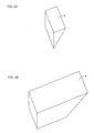
- Figs. 2A and 2B show keys 3 and 4 corresponding to the notch 2.
- an insulated bearing having an insulation layer on its outer ring is used.
- the outer ring 1 having the anticreep device as shown in Fig. 1 since it has a complicated structure like the notch 2, its finish processing becomes very complicated. Especially, when the notch 2 is small in dimension and the insulation film is formed, since its finish processing cannot be performed by a machine and it has to be manually processed in some cases, the number of processing steps of the bearing is increased. Furthermore, the finish processing for notched wall surfaces 2a and 2b shown in Fig. 3 cannot be performed in some cases.
- the contact area between the notch 2 and the key 3 is small, the key 3 is largely abraded due to the vibration at the time of the rotation of the bearing, so that the structure is not superior in durability.
- it is considered to increase the size of the notch 2, however, it is limited in order to maintain the strength of the bearing itself.
- the insulation film is formed on its outer diameter surface by spraying ceramic and the like to the outer ring.
- the insulation film is sprayed to the outer ring having the anticreep device as shown in Fig. 1, when it is assumed that the insulation film is sprayed from direction "A" as shown in Fig. 3, the insulation film is not sufficiently formed on both wall surfaces 2a and 2b of the notch.
- the film is likely to be damaged by stress concentration, which lowers the insulation performance of the bearing.
- a rolling bearing according to the present invention comprises an inner ring, an outer ring, and rolling elements arranged between the inner ring and the outer ring, and the outer ring has a flat surface cut by a plane connecting any one point of its outer diameter surface to any two points of its end face.
- the anticreep device since the anticreep device has a simple structure, its finish process can be simple and the number of processing steps can be reduced.
- the rolling bearing is preferably an insulated bearing in which an insulation film is formed on the outer diameter surface of the outer ring or the inner diameter surface of the inner ring. According to the rolling bearing having the above constitution, even when the insulation film is formed on the surface of the anticreep device, since the insulation film can be formed on the cut flat surface and its vicinity by spraying from one direction, the number of spraying steps can be reduced. In addition, the film thickness of the insulation film can be easily uniformed at each part.
- the rolling element may be a ball or a roller.
- the rolling bearing comprising the anticreep device in which its finish processing is simple and the anticreep function can be maintained for a long period of time.
- the rolling bearing comprising the anticreep device in which the number of spraying steps of the insulation film can be reduced and the film thickness is easily managed and the insulation film can be prevented from being damaged due to the stress concentration at the time of the rotation.
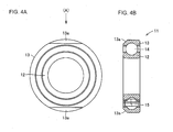
- Figs. 4A and 4B are front view and side sectional view showing a four-point contact ball bearing 11, respectively according to one embodiment of the present invention.
- Fig. 5 is a perspective view showing an outer ring 13 used in the four-point contact ball bearing 11 as shown in Figs. 4A and 4B.
- Figs. 6A and 6B are perspective views showing keys 16 and 17 for fixing the outer ring 13 to a housing.
- the four-point contact ball bearing 11 comprises an inner ring 12, the outer ring 13, balls 14 arranged between the inner ring 12 and the outer ring 13 as rolling elements, and a retainer 15 holding intervals of the balls 14.
- the outer ring 13 has a flat surface 13a cut by a plane that connects any one point "P" on its outer diameter surface to any two points "Q" and "R” at its end face.
- an anticreep device having a simple structure can be provided, its finish processing can be simple and the number of processing steps can be reduced.
- a key 17 having a massive pillar part at the rear part of the abutment part of the cut flat surface 13a as shown in Fig. 6B may be used.
- the four-point contact ball bearing 11 is used as an insulated bearing for supporting a rotation shaft of an electric motor including a railcar main electric motor, a wind power generator, an inverter motor or the like, an insulation film is formed by spraying ceramic and the like to the outer diameter surface of the outer ring 13.
- the insulation film When the insulation film is formed on the outer diameter surface of the outer diameter 13 provided with the cut flat surface 13a, as shown in Fig. 4A, the insulation film can be uniformly formed on the cut flat surface and its vicinity by spraying from direction "A".
- the cost of the bearing can be low.
- the film thickness can be easily uniformed at each part.
- an insulation film may be formed on the inner diameter surface of the inner ring 12 other than the outer diameter surface of the outer ring 13.
- the cut flat surfaces 13a are provided at two parts of the outer ring 13 in the above embodiment, the present invention is not limited to this.
- the cut flat surface 13a may be provided at one part or the cut flat surfaces 13a may be provided at two or more parts.
- the angle formed between the cut flat surface 13a and a surface perpendicular to a bearing rotation axis is desirably about 45 degrees in view of the strength of the key 16 and a wedge effect as the anticreep device.
- the strength of the key 16 is lowered and when the angle is too large, the anti-creep function is lowered.
- the present invention is not limited to this.
- the present invention can be applied to various kinds of rolling bearings such as a deep groove ball bearing, an angular ball bearing, a self-aligning roller bearing, and a cylindrical roller bearing or a conical roller bearing regardless of the configuration of the bearing itself and whether the rolling element is a ball or roller.
- the present invention is not limited to this.
- the present invention can be applied to a double-row rolling bearing in which rolling elements are arranged in double rows between an inner ring and an outer ring.
- the present invention can be advantageously applied to a rolling bearing having an insulation layer on its race ring.
Landscapes
- Engineering & Computer Science (AREA)
- General Engineering & Computer Science (AREA)
- Mechanical Engineering (AREA)
- Manufacturing & Machinery (AREA)
- Rolling Contact Bearings (AREA)
Abstract
Description
- The present invention relates to a rolling bearing and more particularly to a rolling bearing having an insulation layer on its race ring.
- Conventionally, the rolling bearing has comprised an anticreep device disclosed in
Japanese Utility Model Publication No. 7-8913 - There are various kinds of anticreep devices, and a rolling bearing having an outer ring as shown in Fig. 1 has been known in general.
- According to Fig. 1, a
notch 2 having a certain width is provided from the outer diameter surface to the end face of anouter ring 1. In addition, Figs. 2A and 2B showkeys notch 2. - When the rolling bearing having the
outer ring 1 as shown in Fig. 1 is mounted to a shaft, a recessed part is provided at a part corresponding to thenotch 2, in the housing and the housing and theouter ring 2 are fixed by thekey 3, whereby a creep is prevented. - As a bearing for supporting a rotation shaft of an electric motor including a railcar main electric motor, a wind power generator, an inverter motor or the like, an insulated bearing having an insulation layer on its outer ring is used.
- According to the
outer ring 1 having the anticreep device as shown in Fig. 1, since it has a complicated structure like thenotch 2, its finish processing becomes very complicated. Especially, when thenotch 2 is small in dimension and the insulation film is formed, since its finish processing cannot be performed by a machine and it has to be manually processed in some cases, the number of processing steps of the bearing is increased. Furthermore, the finish processing fornotched wall surfaces - In addition, since the contact area between the
notch 2 and thekey 3 is small, thekey 3 is largely abraded due to the vibration at the time of the rotation of the bearing, so that the structure is not superior in durability. In order to increase the contact area, it is considered to increase the size of thenotch 2, however, it is limited in order to maintain the strength of the bearing itself. - According to the insulated bearing, the insulation film is formed on its outer diameter surface by spraying ceramic and the like to the outer ring. In the case where the insulation film is sprayed to the outer ring having the anticreep device as shown in Fig. 1, when it is assumed that the insulation film is sprayed from direction "A" as shown in Fig. 3, the insulation film is not sufficiently formed on both
wall surfaces - In this case, when the insulation film is to be formed on the
wall surface 2a, the spraying needs to be performed from direction "B" and when the insulation film is to be formed on thewall surface 2b, the spraying needs to be performed from direction "C". As a result, the number of spraying steps is increased. - In addition, when the spraying is performed from the two directions "B" and "C", the spraying is performed to a
bottom 2c of thenotch 2 and the vicinity of thenotch 2 twice, which causes a variation in film thickness of the insulation film at each part. - Still furthermore, at the corner parts formed between both
wall surface bottom 2c of thenotch 2, the film is likely to be damaged by stress concentration, which lowers the insulation performance of the bearing. - Thus, it is an object of the present invention to provide a rolling bearing comprising an anticreep device in which its finish processing is simple and an anticreep function is prevented from being lowered due to abrasion.
- In addition, when the above bearing is applied to a bearing having an insulation layer, it is an object of the present invention to provide a rolling bearing comprising an anticreep device in which the number of spraying steps of the insulation film is reduced, a film thickness is easily managed, and the insulation film is prevented from being damaged due to stress concentration at the time of rotation.
- A rolling bearing according to the present invention comprises an inner ring, an outer ring, and rolling elements arranged between the inner ring and the outer ring, and the outer ring has a flat surface cut by a plane connecting any one point of its outer diameter surface to any two points of its end face.
- According to the above constitution, as compared with the conventional constitution, since the anticreep device has a simple structure, its finish process can be simple and the number of processing steps can be reduced.
- In addition, since the contact area between the cut flat surface and the key is large, the contact stress between both members is small, so that abrasion of the key due to vibration and the like can be prevented, and a high anticreep function can be maintained for a long period of time.
- The rolling bearing is preferably an insulated bearing in which an insulation film is formed on the outer diameter surface of the outer ring or the inner diameter surface of the inner ring. According to the rolling bearing having the above constitution, even when the insulation film is formed on the surface of the anticreep device, since the insulation film can be formed on the cut flat surface and its vicinity by spraying from one direction, the number of spraying steps can be reduced. In addition, the film thickness of the insulation film can be easily uniformed at each part.
- Furthermore, since there is no corner part bending inside in the cut flat surface, stress concentration is not generated, so that the insulation performance of the bearing is not lowered due to the damage of the insulation film, and the rolling bearing can be superior in durability.
- The rolling element may be a ball or a roller.
- According to the present invention, there is provided the rolling bearing comprising the anticreep device in which its finish processing is simple and the anticreep function can be maintained for a long period of time.
- Furthermore, when it is applied to the insulated bearing, there can be provided the rolling bearing comprising the anticreep device in which the number of spraying steps of the insulation film can be reduced and the film thickness is easily managed and the insulation film can be prevented from being damaged due to the stress concentration at the time of the rotation.
-
- Fig. 1 is a perspective view showing an outer ring used in a rolling bearing provided with a conventional anticreep device;
- Fig. 2A is a perspective view showing one example of a key corresponding to a notch of the outer ring in Fig. 1;
- Fig. 2B is a perspective view showing another example of a key corresponding to the notch of the outer ring in Fig. 1;
- Fig. 3 is a front view showing the outer ring viewed from a direction shown by an arrow "A" shown in Fig. 1;
- Fig. 4A is a front view showing a four-point contact bearing according to one embodiment of the present invention;
- Fig. 4B is a side sectional view showing the four-point contact bearing according to one embodiment of the present invention;
- Fig. 5 is a perspective view showing an outer ring used in the four-point contact ball bearing shown in Fig. 4;
- Fig. 6A is a perspective view showing one example of a key corresponding to a cut flat surface of the outer ring shown in Fig. 5; and
- Fig. 6B is a perspective view showing another example of a key corresponding to the cut flat surface of the outer ring shown in Fig. 5.
- Figs. 4A and 4B are front view and side sectional view showing a four-point contact ball bearing 11, respectively according to one embodiment of the present invention. In addition, Fig. 5 is a perspective view showing an
outer ring 13 used in the four-point contact ball bearing 11 as shown in Figs. 4A and 4B. Furthermore, Figs. 6A and 6B are perspectiveviews showing keys outer ring 13 to a housing. - As shown in Fig. 4A, the four-point contact ball bearing 11 comprises an
inner ring 12, theouter ring 13,balls 14 arranged between theinner ring 12 and theouter ring 13 as rolling elements, and aretainer 15 holding intervals of theballs 14. As shown in Fig. 5, theouter ring 13 has aflat surface 13a cut by a plane that connects any one point "P" on its outer diameter surface to any two points "Q" and "R" at its end face. - When the four-point ball bearing 11 having the
outer ring 13 as shown in Fig. 5 is mounted to a shaft, a recessed part is provided at a part corresponding to the cutflat surface 13a, in the housing and the housing and theouter ring 13 are fixed by thekey 16, whereby a creep is prevented. - According to the above constitution, as compared with the conventional constitution, since an anticreep device having a simple structure can be provided, its finish processing can be simple and the number of processing steps can be reduced.
- In addition, since the contact area between the cut
flat surface 13a and thekey 16 as shown in Fig. 6A is large, the contact stress between both members is small, so that abrasion of thekey 16 due to vibration and the like can be prevented, and a high anticreep function can be maintained for a long period of time. In addition, in order to enhance the strength of the key corresponding to the cutflat surface 13a, akey 17 having a massive pillar part at the rear part of the abutment part of the cutflat surface 13a as shown in Fig. 6B may be used. - When the four-point
contact ball bearing 11 is used as an insulated bearing for supporting a rotation shaft of an electric motor including a railcar main electric motor, a wind power generator, an inverter motor or the like, an insulation film is formed by spraying ceramic and the like to the outer diameter surface of theouter ring 13. - When the insulation film is formed on the outer diameter surface of the
outer diameter 13 provided with the cutflat surface 13a, as shown in Fig. 4A, the insulation film can be uniformly formed on the cut flat surface and its vicinity by spraying from direction "A". - As a result, since the number of spraying steps of the insulation film can be reduced, the cost of the bearing can be low. In addition, the film thickness can be easily uniformed at each part.
- In addition, an insulation film may be formed on the inner diameter surface of the
inner ring 12 other than the outer diameter surface of theouter ring 13. - Although the cut
flat surfaces 13a are provided at two parts of theouter ring 13 in the above embodiment, the present invention is not limited to this. For example, the cutflat surface 13a may be provided at one part or the cutflat surfaces 13a may be provided at two or more parts. - Furthermore, the angle formed between the cut
flat surface 13a and a surface perpendicular to a bearing rotation axis is desirably about 45 degrees in view of the strength of the key 16 and a wedge effect as the anticreep device. When the angle is too small, the strength of the key 16 is lowered and when the angle is too large, the anti-creep function is lowered. - Although the four-point ball bearing is shown in the above embodiment, the present invention is not limited to this. For example, the present invention can be applied to various kinds of rolling bearings such as a deep groove ball bearing, an angular ball bearing, a self-aligning roller bearing, and a cylindrical roller bearing or a conical roller bearing regardless of the configuration of the bearing itself and whether the rolling element is a ball or roller.
- Furthermore, although the single-row four-point contact ball bearing is shown in the above embodiment, the present invention is not limited to this. For example, the present invention can be applied to a double-row rolling bearing in which rolling elements are arranged in double rows between an inner ring and an outer ring.
- Although the embodiments of the present invention have been described with reference to the drawings in the above, the present invention is not limited to the above-illustrated embodiments. Various kinds of modifications and variations may be added to the illustrated embodiments within the same or equal scope of the present invention.
- The present invention can be advantageously applied to a rolling bearing having an insulation layer on its race ring.
Claims (5)
- A rolling bearing comprising:an inner ring;an outer ring; androlling elements arranged between said inner ring and said outer ring, whereinsaid outer ring has a flat surface cut by a plane connecting any one point of its outer diameter surface to any two points of its end face.
- The rolling bearing according to claim 1, wherein
an insulation film is formed on the outer diameter surface of said outer ring. - The rolling bearing according to claim 1, wherein
an insulation film is formed on the inner diameter surface of said inner ring. - The rolling bearing according to claim 1, wherein
said rolling element is a ball. - The rolling bearing according to claim 1, wherein
said rolling element is a roller.
Applications Claiming Priority (2)
| Application Number | Priority Date | Filing Date | Title |
|---|---|---|---|
| JP2005040326A JP2006226391A (en) | 2005-02-17 | 2005-02-17 | Rolling bearing |
| PCT/JP2006/302624 WO2006088045A1 (en) | 2005-02-17 | 2006-02-15 | Rolling bearing |
Publications (2)
| Publication Number | Publication Date |
|---|---|
| EP1850021A1 true EP1850021A1 (en) | 2007-10-31 |
| EP1850021A4 EP1850021A4 (en) | 2009-11-04 |
Family
ID=36916449
Family Applications (1)
| Application Number | Title | Priority Date | Filing Date |
|---|---|---|---|
| EP06713765A Withdrawn EP1850021A4 (en) | 2005-02-17 | 2006-02-15 | Rolling bearing |
Country Status (4)
| Country | Link |
|---|---|
| EP (1) | EP1850021A4 (en) |
| JP (1) | JP2006226391A (en) |
| CN (1) | CN101120180A (en) |
| WO (1) | WO2006088045A1 (en) |
Families Citing this family (5)
| Publication number | Priority date | Publication date | Assignee | Title |
|---|---|---|---|---|
| JP4843431B2 (en) * | 2006-09-15 | 2011-12-21 | Ntn株式会社 | Insulated rolling bearings and rolling bearings for wind power generators |
| JP2009236287A (en) * | 2008-03-28 | 2009-10-15 | Jtekt Corp | Rolling bearing device for wheel |
| CN101684841B (en) * | 2008-09-26 | 2011-07-20 | 上海联合滚动轴承有限公司 | Pitch bearing used on wind driven generator |
| JP2011252523A (en) * | 2010-06-01 | 2011-12-15 | Jtekt Corp | Rolling bearing device |
| DE102016208286B4 (en) * | 2015-05-28 | 2026-06-18 | Robert Bosch Gmbh | Roller bearing and hydrostatic axial piston machine in swashplate design with one roller bearing |
Family Cites Families (7)
| Publication number | Priority date | Publication date | Assignee | Title |
|---|---|---|---|---|
| JPS49138249U (en) * | 1973-03-30 | 1974-11-28 | ||
| JPS52152932U (en) * | 1976-05-15 | 1977-11-19 | ||
| JPS5510111A (en) * | 1978-07-04 | 1980-01-24 | Nippon Seiko Kk | Roller bearing for preventing electrolytic corrosion |
| JP2604774Y2 (en) | 1993-07-15 | 2000-06-05 | 日本オートマチックマシン株式会社 | Wire gripper |
| JP3821968B2 (en) * | 1998-11-06 | 2006-09-13 | 株式会社ジェイテクト | Anti-corrosion rolling bearing |
| DE10161820A1 (en) * | 2000-12-14 | 2002-09-05 | Ntn Toyo Bearing Co Ltd | Electric corrosion prevention type bearing has reference plane provided to internal surface of outer wheel and subjected to grinding before providing ceramic thermal spraying insulating layer |
| US6666583B2 (en) * | 2001-12-04 | 2003-12-23 | Visteon Global Technologies, Inc. | Bearing retention assembly having cam chamfered bearing race ring |
-
2005
- 2005-02-17 JP JP2005040326A patent/JP2006226391A/en active Pending
-
2006
- 2006-02-15 EP EP06713765A patent/EP1850021A4/en not_active Withdrawn
- 2006-02-15 CN CNA2006800051079A patent/CN101120180A/en active Pending
- 2006-02-15 WO PCT/JP2006/302624 patent/WO2006088045A1/en not_active Ceased
Also Published As
| Publication number | Publication date |
|---|---|
| WO2006088045A1 (en) | 2006-08-24 |
| CN101120180A (en) | 2008-02-06 |
| JP2006226391A (en) | 2006-08-31 |
| EP1850021A4 (en) | 2009-11-04 |
Similar Documents
| Publication | Publication Date | Title |
|---|---|---|
| US6783279B2 (en) | Angular contact ball-bearing cage with lubricant pockets | |
| JP2008180246A (en) | Tapered roller bearing | |
| CN113167320A (en) | Tapered Roller Bearings | |
| EP3779220A1 (en) | Tapered roller bearing | |
| JP2005106234A (en) | Conical roller bearing and method for working conical roller bearing | |
| WO1999002874A1 (en) | Roller bearing | |
| JP2006226391A (en) | Rolling bearing | |
| JP2000120670A (en) | Rolling bearing | |
| JP2002206542A (en) | Electro-corrosion prevention type bearing and method of manufacturing outer ring thereof | |
| US10208797B2 (en) | Tapered roller bearing | |
| JP2009243618A (en) | Rolling bearing | |
| EP1860337B1 (en) | Needle bearing | |
| JP2006144921A (en) | Rolling bearing | |
| JPH09210072A (en) | Angular contact ball bearing with seal | |
| JP2006200677A (en) | Thrust ball bearing | |
| CN108035969A (en) | A kind of reinforced micro- bearing of spy | |
| WO2007043298A1 (en) | Anti-electrolytic corrosion rolling bearing | |
| JP2006177445A (en) | Double-row automatic aligned roller bearing | |
| CN222823549U (en) | A miniature bearing | |
| JP2006300130A (en) | Bearing structure | |
| KR20230048671A (en) | A Roller For Cross-Roller Bearing And A Cross-Roller Bearing Having Therewith | |
| JP2008256116A (en) | Wheel support device | |
| JP2006300128A (en) | Conical roller bearing, pin-type retainer for conical roller bearing, and main spindle supporting structure for wind generator | |
| JP4110764B2 (en) | Thrust roller bearing | |
| JP2007170429A (en) | Angular ball bearing |
Legal Events
| Date | Code | Title | Description |
|---|---|---|---|
| PUAI | Public reference made under article 153(3) epc to a published international application that has entered the european phase |
Free format text: ORIGINAL CODE: 0009012 |
|
| 17P | Request for examination filed |
Effective date: 20070813 |
|
| AK | Designated contracting states |
Kind code of ref document: A1 Designated state(s): DE FR |
|
| DAX | Request for extension of the european patent (deleted) | ||
| RBV | Designated contracting states (corrected) |
Designated state(s): DE FR |
|
| A4 | Supplementary search report drawn up and despatched |
Effective date: 20091006 |
|
| RIC1 | Information provided on ipc code assigned before grant |
Ipc: F16C 33/62 20060101ALI20090930BHEP Ipc: F16C 33/58 20060101ALI20090930BHEP Ipc: F16C 19/26 20060101ALI20090930BHEP Ipc: F16C 33/64 20060101ALI20090930BHEP Ipc: F16C 19/06 20060101ALI20090930BHEP Ipc: F16C 35/077 20060101AFI20060828BHEP |
|
| 17Q | First examination report despatched |
Effective date: 20100215 |
|
| STAA | Information on the status of an ep patent application or granted ep patent |
Free format text: STATUS: THE APPLICATION HAS BEEN WITHDRAWN |
|
| 18W | Application withdrawn |
Effective date: 20100601 |