EP1850008A1 - Vane pump - Google Patents
Vane pump Download PDFInfo
- Publication number
- EP1850008A1 EP1850008A1 EP06712698A EP06712698A EP1850008A1 EP 1850008 A1 EP1850008 A1 EP 1850008A1 EP 06712698 A EP06712698 A EP 06712698A EP 06712698 A EP06712698 A EP 06712698A EP 1850008 A1 EP1850008 A1 EP 1850008A1
- Authority
- EP
- European Patent Office
- Prior art keywords
- vane
- rotor
- pump room
- oil supply
- passage
- Prior art date
- Legal status (The legal status is an assumption and is not a legal conclusion. Google has not performed a legal analysis and makes no representation as to the accuracy of the status listed.)
- Granted
Links
Images
Classifications
-
- F—MECHANICAL ENGINEERING; LIGHTING; HEATING; WEAPONS; BLASTING
- F04—POSITIVE - DISPLACEMENT MACHINES FOR LIQUIDS; PUMPS FOR LIQUIDS OR ELASTIC FLUIDS
- F04C—ROTARY-PISTON, OR OSCILLATING-PISTON, POSITIVE-DISPLACEMENT MACHINES FOR LIQUIDS; ROTARY-PISTON, OR OSCILLATING-PISTON, POSITIVE-DISPLACEMENT PUMPS
- F04C18/00—Rotary-piston pumps specially adapted for elastic fluids
- F04C18/30—Rotary-piston pumps specially adapted for elastic fluids having the characteristics covered by two or more of groups F04C18/02, F04C18/08, F04C18/22, F04C18/24, F04C18/48, or having the characteristics covered by one of these groups together with some other type of movement between co-operating members
- F04C18/34—Rotary-piston pumps specially adapted for elastic fluids having the characteristics covered by two or more of groups F04C18/02, F04C18/08, F04C18/22, F04C18/24, F04C18/48, or having the characteristics covered by one of these groups together with some other type of movement between co-operating members having the movement defined in group F04C18/08 or F04C18/22 and relative reciprocation between the co-operating members
- F04C18/344—Rotary-piston pumps specially adapted for elastic fluids having the characteristics covered by two or more of groups F04C18/02, F04C18/08, F04C18/22, F04C18/24, F04C18/48, or having the characteristics covered by one of these groups together with some other type of movement between co-operating members having the movement defined in group F04C18/08 or F04C18/22 and relative reciprocation between the co-operating members with vanes reciprocating with respect to the inner member
-
- F—MECHANICAL ENGINEERING; LIGHTING; HEATING; WEAPONS; BLASTING
- F04—POSITIVE - DISPLACEMENT MACHINES FOR LIQUIDS; PUMPS FOR LIQUIDS OR ELASTIC FLUIDS
- F04C—ROTARY-PISTON, OR OSCILLATING-PISTON, POSITIVE-DISPLACEMENT MACHINES FOR LIQUIDS; ROTARY-PISTON, OR OSCILLATING-PISTON, POSITIVE-DISPLACEMENT PUMPS
- F04C29/00—Component parts, details or accessories of pumps or pumping installations, not provided for in groups F04C18/00 - F04C28/00
- F04C29/02—Lubrication; Lubricant separation
- F04C29/026—Lubricant separation
-
- F—MECHANICAL ENGINEERING; LIGHTING; HEATING; WEAPONS; BLASTING
- F04—POSITIVE - DISPLACEMENT MACHINES FOR LIQUIDS; PUMPS FOR LIQUIDS OR ELASTIC FLUIDS
- F04C—ROTARY-PISTON, OR OSCILLATING-PISTON, POSITIVE-DISPLACEMENT MACHINES FOR LIQUIDS; ROTARY-PISTON, OR OSCILLATING-PISTON, POSITIVE-DISPLACEMENT PUMPS
- F04C18/00—Rotary-piston pumps specially adapted for elastic fluids
- F04C18/30—Rotary-piston pumps specially adapted for elastic fluids having the characteristics covered by two or more of groups F04C18/02, F04C18/08, F04C18/22, F04C18/24, F04C18/48, or having the characteristics covered by one of these groups together with some other type of movement between co-operating members
- F04C18/34—Rotary-piston pumps specially adapted for elastic fluids having the characteristics covered by two or more of groups F04C18/02, F04C18/08, F04C18/22, F04C18/24, F04C18/48, or having the characteristics covered by one of these groups together with some other type of movement between co-operating members having the movement defined in group F04C18/08 or F04C18/22 and relative reciprocation between the co-operating members
- F04C18/344—Rotary-piston pumps specially adapted for elastic fluids having the characteristics covered by two or more of groups F04C18/02, F04C18/08, F04C18/22, F04C18/24, F04C18/48, or having the characteristics covered by one of these groups together with some other type of movement between co-operating members having the movement defined in group F04C18/08 or F04C18/22 and relative reciprocation between the co-operating members with vanes reciprocating with respect to the inner member
- F04C18/3441—Rotary-piston pumps specially adapted for elastic fluids having the characteristics covered by two or more of groups F04C18/02, F04C18/08, F04C18/22, F04C18/24, F04C18/48, or having the characteristics covered by one of these groups together with some other type of movement between co-operating members having the movement defined in group F04C18/08 or F04C18/22 and relative reciprocation between the co-operating members with vanes reciprocating with respect to the inner member the inner and outer member being in contact along one line or continuous surface substantially parallel to the axis of rotation
- F04C18/3442—Rotary-piston pumps specially adapted for elastic fluids having the characteristics covered by two or more of groups F04C18/02, F04C18/08, F04C18/22, F04C18/24, F04C18/48, or having the characteristics covered by one of these groups together with some other type of movement between co-operating members having the movement defined in group F04C18/08 or F04C18/22 and relative reciprocation between the co-operating members with vanes reciprocating with respect to the inner member the inner and outer member being in contact along one line or continuous surface substantially parallel to the axis of rotation the surfaces of the inner and outer member, forming the inlet and outlet opening
-
- F—MECHANICAL ENGINEERING; LIGHTING; HEATING; WEAPONS; BLASTING
- F04—POSITIVE - DISPLACEMENT MACHINES FOR LIQUIDS; PUMPS FOR LIQUIDS OR ELASTIC FLUIDS
- F04C—ROTARY-PISTON, OR OSCILLATING-PISTON, POSITIVE-DISPLACEMENT MACHINES FOR LIQUIDS; ROTARY-PISTON, OR OSCILLATING-PISTON, POSITIVE-DISPLACEMENT PUMPS
- F04C25/00—Adaptations of pumps for special use of pumps for elastic fluids
- F04C25/02—Adaptations of pumps for special use of pumps for elastic fluids for producing high vacuum
-
- F—MECHANICAL ENGINEERING; LIGHTING; HEATING; WEAPONS; BLASTING
- F04—POSITIVE - DISPLACEMENT MACHINES FOR LIQUIDS; PUMPS FOR LIQUIDS OR ELASTIC FLUIDS
- F04C—ROTARY-PISTON, OR OSCILLATING-PISTON, POSITIVE-DISPLACEMENT MACHINES FOR LIQUIDS; ROTARY-PISTON, OR OSCILLATING-PISTON, POSITIVE-DISPLACEMENT PUMPS
- F04C28/00—Control of, monitoring of, or safety arrangements for, pumps or pumping installations specially adapted for elastic fluids
- F04C28/06—Control of, monitoring of, or safety arrangements for, pumps or pumping installations specially adapted for elastic fluids specially adapted for stopping, starting, idling or no-load operation
-
- F—MECHANICAL ENGINEERING; LIGHTING; HEATING; WEAPONS; BLASTING
- F04—POSITIVE - DISPLACEMENT MACHINES FOR LIQUIDS; PUMPS FOR LIQUIDS OR ELASTIC FLUIDS
- F04C—ROTARY-PISTON, OR OSCILLATING-PISTON, POSITIVE-DISPLACEMENT MACHINES FOR LIQUIDS; ROTARY-PISTON, OR OSCILLATING-PISTON, POSITIVE-DISPLACEMENT PUMPS
- F04C28/00—Control of, monitoring of, or safety arrangements for, pumps or pumping installations specially adapted for elastic fluids
- F04C28/28—Safety arrangements; Monitoring
-
- F—MECHANICAL ENGINEERING; LIGHTING; HEATING; WEAPONS; BLASTING
- F04—POSITIVE - DISPLACEMENT MACHINES FOR LIQUIDS; PUMPS FOR LIQUIDS OR ELASTIC FLUIDS
- F04C—ROTARY-PISTON, OR OSCILLATING-PISTON, POSITIVE-DISPLACEMENT MACHINES FOR LIQUIDS; ROTARY-PISTON, OR OSCILLATING-PISTON, POSITIVE-DISPLACEMENT PUMPS
- F04C29/00—Component parts, details or accessories of pumps or pumping installations, not provided for in groups F04C18/00 - F04C28/00
- F04C29/02—Lubrication; Lubricant separation
-
- F—MECHANICAL ENGINEERING; LIGHTING; HEATING; WEAPONS; BLASTING
- F04—POSITIVE - DISPLACEMENT MACHINES FOR LIQUIDS; PUMPS FOR LIQUIDS OR ELASTIC FLUIDS
- F04C—ROTARY-PISTON, OR OSCILLATING-PISTON, POSITIVE-DISPLACEMENT MACHINES FOR LIQUIDS; ROTARY-PISTON, OR OSCILLATING-PISTON, POSITIVE-DISPLACEMENT PUMPS
- F04C29/00—Component parts, details or accessories of pumps or pumping installations, not provided for in groups F04C18/00 - F04C28/00
- F04C29/02—Lubrication; Lubricant separation
- F04C29/023—Lubricant distribution through a hollow driving shaft
-
- F—MECHANICAL ENGINEERING; LIGHTING; HEATING; WEAPONS; BLASTING
- F04—POSITIVE - DISPLACEMENT MACHINES FOR LIQUIDS; PUMPS FOR LIQUIDS OR ELASTIC FLUIDS
- F04C—ROTARY-PISTON, OR OSCILLATING-PISTON, POSITIVE-DISPLACEMENT MACHINES FOR LIQUIDS; ROTARY-PISTON, OR OSCILLATING-PISTON, POSITIVE-DISPLACEMENT PUMPS
- F04C2240/00—Components
- F04C2240/50—Bearings
- F04C2240/51—Bearings for cantilever assemblies
-
- F—MECHANICAL ENGINEERING; LIGHTING; HEATING; WEAPONS; BLASTING
- F04—POSITIVE - DISPLACEMENT MACHINES FOR LIQUIDS; PUMPS FOR LIQUIDS OR ELASTIC FLUIDS
- F04C—ROTARY-PISTON, OR OSCILLATING-PISTON, POSITIVE-DISPLACEMENT MACHINES FOR LIQUIDS; ROTARY-PISTON, OR OSCILLATING-PISTON, POSITIVE-DISPLACEMENT PUMPS
- F04C2240/00—Components
- F04C2240/60—Shafts
-
- F—MECHANICAL ENGINEERING; LIGHTING; HEATING; WEAPONS; BLASTING
- F04—POSITIVE - DISPLACEMENT MACHINES FOR LIQUIDS; PUMPS FOR LIQUIDS OR ELASTIC FLUIDS
- F04C—ROTARY-PISTON, OR OSCILLATING-PISTON, POSITIVE-DISPLACEMENT MACHINES FOR LIQUIDS; ROTARY-PISTON, OR OSCILLATING-PISTON, POSITIVE-DISPLACEMENT PUMPS
- F04C2270/00—Control; Monitoring or safety arrangements
- F04C2270/70—Safety, emergency conditions or requirements
Definitions
- the present invention relates to a vane pump, and in particular to a vane pump adapted to intermittently feed a lubricating oil to a pump room owing to rotation of a rotor.
- a vane pump including: a housing having a pump room in which an approximately circular, inner wall is formed; a rotor rotating at an eccentric position relative to the center of the pump room and sliding in contact with a part of the inner wall of the pump room; and a vane rotated by the rotor, for dividing the pump room into a plurality of spaces full-time (Patent Document 1).
- Patent Document 1 Japanese Patent No. 3107906 (especially Figure 3)
- the lubricating oil has, in addition to an effect of lubricating the vane and the pump room, an effect of sealing a gap between the vane and the pump room to maintain airtight of a space divided by the vane, and when the lubricating oil is not sufficiently fed into the pump room, such as at the time of engine start, this sealing is not fully effected.
- an object of the present invention is to provide a vane pump which can rapidly exert its original performance, even when an amount of the lubricating oil fed to a pump room is small, such as at the time of engine start.
- the vane pump according to the present invention is a vane pump including: a housing having a pump room in which an approximately circular, inner wall is formed; a rotor rotating at an eccentric position relative to the center of the pump room and sliding in contact with a part of the inner wall of the pump room; and a vane rotated by the rotor, for dividing the pump room into a plurality of spaces full-time, wherein in the housing, among spaces divided by a center line drawn between the center of the pump room and the center of rotation of the rotor, an intake passage in one space and an exhaust passage in the other space are formed, respectively, further, in the rotor and the housing, an oil supply passage intermittently communicating with the pump room owing to rotation of the rotor is formed, and a lubricating oil is intermittently fed through a communicating hole of the oil supply passage formed in the pump room, characterized in that the communicating hole is formed in a space on the side of the exhaust passage from the center line in the pump room, and the vane passes the communicating hole,
- the pump room is divided into three spaces by the vane, and among them, the space on the side where the rotor contacts with the pump room is divided into a space on the side of the intake passage and a space on the side of the exhaust passage relative to the center line by the rotor.
- a pressure in the space on the side, where the rotor contacts with the pump room, of the intake passage from the center line is made negative due to suction of a gas through the intake passage, and a pressure in the space on the side where the rotor does not contact with the pump room is made negative, because its volume is increased by rotation of the vane.
- the space on the side, where the rotor contacts with the pump room, of the exhaust passage from the center line has a higher pressure than the space in which the pressure is negative due to an increase of the volume as described above, because, while its volume is decreased, the lubricating oil and a gas are discharged from the exhaust passage.
- a differential pressure between the space having a negative pressure due to an increase of the volume and the space having a higher pressure than the relevant space is also generated, thereby the lubricating oil in the space having a higher pressure is spouted into the space having a negative pressure through a gap between the vane and the pump room.
- the lubricating oil spouted into the space having a negative pressure is spouted in the direction opposite to the rotational direction of the vane, so that the lubricating oil positively impact on the vane which subsequently passes the communicating hole.
- the spouted lubricating oil seals the gap between the vane and the pump room, accordingly the vane pump can rapidly exert its original performance, even if the lubricating oil is not sufficiently fed into the pump room.
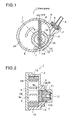
- FIGS 1 to 3 show a vane pump 1 of this embodiment.
- This vane pump 1 is fixed on the side surface of an engine of an automobile not shown, and adapted to generate a negative pressure in a booster of a brake control system not shown.
- This vane pump 1 includes: a housing 2 having an approximately circular pump room 2A formed therein; a rotor 3 rotated at an eccentric position relative to the center of the pump room 2A by a driving force of the engine; a hollow vane 4 rotated by the rotor 3, for dividing the pump room 2A into a plurality of spaces full-time; and a cover 5 for covering the pump room 2A.
- an intake passage 6 located above the pump room 2A, in communication with the booster of the brake control system, for sucking in a gas from the booster, and an exhaust passage 7 located below the pump room 2A, for discharging the gas sucked in from the booster and a lubricating oil fed from an oil supply groove 13 described below are provided, respectively.
- a check valve 8 is provided in the intake passage 6, to hold a negative pressure in the booster, especially at stop of the engine.
- the rotor 3 includes a cylindrical rotor portion 3A rotating in the pump room 2A, an outer surface of the rotor portion 3A contacts with an inner wall surface of the pump room 2A, and further, oppositely across a center line L drawn between the center of the rotor portion 3A and the center of the pump room 2A, the intake passage 6 and the exhaust passage 7 are disposed.
- an upstream side in the rotational direction means a space adjacent to a clockwise side from a line drawn between the center of rotation of the rotor 3 and an arbitrary point of the pump room 2A
- a downstream side in the rotational direction means a space adjacent to a counterclockwise side from the line.
- a hollow portion 3a and a groove 9 in the diametrical direction are provided, and the vane 4 is adapted to move slidably along in the groove 9 in the direction perpendicular to the axial direction of the rotor 3.
- caps 10 of which fore ends are formed to be semicircular are provided, and the fore end of this cap 10 slides in contact with the inner wall surface of the pump room 2A and a slight gap is present between the vane 4 and the cap 10.
- the lubricating oil is arranged to be fed through an oil supply groove 13, and a communicating hole of the oil supply groove 13 is formed on the downstream side in the rotational direction of the vane 4 from a position at which the exhaust passage 7 is formed. Therefore, the vane 4 is arranged to pass the oil supply groove 13 after passing the exhaust passage 7, so that the lubricating oil fed from the oil supply groove 13 is not discharged, just as it is, from the exhaust passage 7.
- the vane 4 is shown as oriented in the vertical direction, hereinafter for illustrative purposes, a space situated on the right side shown of the vane 4 and above the rotor portion 3A in the pump room 2A is called the "first space A”, a space situated on the left side of the vane 4 is called the “second space B” and a space situated on the right side of the vane 4 and below the rotor portion 3A is called the "third space C".
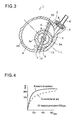
- Figure 2 shows a cross-sectional view taken along the line II-II in situations shown in Figure 1.
- a bearing 2B adjacent to the pump room 2A for supporting the rotor 3 is formed, and the cover 5 is provided on the opposite side to the bearing 2B.
- the rotor 3 includes a shank 3B supported by the bearing 2B, for driving rotationally the rotor portion 3A, and the shank 3B projects from the bearing 2B to the right side shown, being linked to a coupling 11 driven rotationally by a camshaft of the engine.
- end surfaces of the rotor portion 3A and the vane 4 on the left side shown slide in contact with the cover 5, and further an end surface of the vane 4 on the right side rotates slidably in contact with an inner surface of the pump room 2A on the side of the bearing 2B.
- a bottom surface 9a of the groove 9 formed in the rotor 3 is formed on the side of the shank 3B slightly from a surface on which the vane 4 and the pump room 2A slide, and a gap between the vane 4 and the bottom surface 9a is present.
- an oil passage 12 for circulating the lubricating oil from the engine and constituting an oil supply passage is formed, and this oil passage 12 branches at a predetermined position in the same direction as the groove 9 and includes a branch passage 12a open into an outer surface of the shank 3B.
- an oil supply groove 13 formed in the axial direction of the bearing 2B, for constituting the oil supply passage forming the communicating hole into the pump room 2A is formed, and as shown in Figure 1, a width of the oil supply groove 13 along the rotational direction of the vane 4 is formed to be not smaller than that of the vane 4.
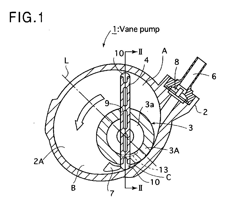
- the first space A in Figure 1 is located on the left side of the vane 4 in this figure ( Figure 3) due to rotation of the rotor 3, and the second space B in Figure 1 is located on the right lower side of the vane 4 and the rotor 3 in this figure ( Figure 3).
- the first space A has an increased volume compared to that in Figure 1, and further sucked in a gas from the booster through the intake passage 6, accordingly a pressure in the first space A becomes negative.
- a volume of the second space B is decreased compared to that in Figure 1, and also the lubricating oil along with a gas in the second space B is discharged from the exhaust passage 7, at this time, in order to force the lubricating oil in the exhaust passage 7 to be removed, the gas in the second space B is compressed to have a higher pressure than the first space A.
- a differential pressure between the first space A and the second space B is generated, as the result, the lubricating oil which could not be removed through the exhaust passage 7 by the vane 4 is sprayed into the first space A through the gap between the pump room 2A and the vane 4, and the gap between the vane 4 and the cap 10, respectively, due to the differential pressure.
- the branch passage 12a in the oil supply passage and the groove 9 of the rotor 3 are placed in the same direction, if the vane 4 and the oil supply groove 13 coincide with each other in position as shown, at the same time, the branch passage 12a and the oil supply groove 13 also coincide with each other.
- the lubricating oil from the oil supply groove 13 is made misty to be spouted into the first space A through a bottom portion of the rotor portion 3A downstream, due to a negative pressure in the first space A. That is, in this embodiment, to the first space A, the lubricating oil is adapted to be fed at two steps in form of the lubricating oil sprayed from the second space B as described above and the lubricating oil sprayed from the bottom portion of the rotor portion 3A downstream.
- the lubricating oil can rapidly circulate around in the gap between the vane 4 and the pump room 2A or the gap between the cap 10 and the pump room 2A, when the lubricating oil is not sufficiently distributed in the vane pump 1, especially such as at start of an engine. Then, the lubricating oil not only lubricates the inside of the vane pump 1, but plays a role of sealing, and by sealing the gap between the vane 4 and the pump room 2A etc. with the lubricating oil, for example, airtight between the second space B and the first space A can be held. Therefore, even immediately after start of an engine, the vane pump 1 can rapidly exert its original performance.
- FIG. 4 shows this with the experimental result.
- an elapsed time from engine start is shown in the horizontal axis
- an ability to generate a negative pressure in a booster is shown in the longitudinal axis, and it may be seen that the vane pump 1 having the configuration of this embodiment denoted by the solid line brings out a predetermined ability to generate a negative pressure more rapidly compared to the vane pump having a conventional configuration denoted by the broken line.
- the oil supply groove 13 may be formed at a position on the side of the exhaust passage 7 relative to the center line L, but it is noted that, if the oil supply groove 13 is positioned on the side too much upstream in the rotational direction of the vane 4, a negative pressure to be generated by increasing a volume of the pump room 2A is reduced due to inflow of the lubricating oil, accordingly suction becomes insufficient, thereby performance of the vane pump cannot be fully provided.
- the width of the oil supply groove 13 in the rotational direction has been set slightly larger to be not smaller than that of the vane 4, but it is noted that, here, if the width of the oil supply groove 13 in the rotational direction is set to be narrower than that of the vane 4, a time for feeding oil is shortened and lubrication cannot be sufficiently performed, and on the contrary, if the width of the oil supply groove 13 in the rotational direction is set to be too wide, an amount of the lubricating oil becomes too large and the vane 4 bears a load, when the lubricating oil is removed.
Landscapes
- Engineering & Computer Science (AREA)
- Mechanical Engineering (AREA)
- General Engineering & Computer Science (AREA)
- Rotary Pumps (AREA)
- Applications Or Details Of Rotary Compressors (AREA)
Abstract
Description
- The present invention relates to a vane pump, and in particular to a vane pump adapted to intermittently feed a lubricating oil to a pump room owing to rotation of a rotor.
- Conventionally, there is known a vane pump including: a housing having a pump room in which an approximately circular, inner wall is formed; a rotor rotating at an eccentric position relative to the center of the pump room and sliding in contact with a part of the inner wall of the pump room; and a vane rotated by the rotor, for dividing the pump room into a plurality of spaces full-time (Patent Document 1).
Then, there is known a vane pump that, in the rotor and the housing described above, an oil supply passage intermittently communicating with a pump room owing to rotation of the rotor is formed, a lubricating oil is intermittently fed through a communicating hole of the oil supply passage formed in the pump room, and the communicating hole is formed at a position on the side of an intake passage from a center line drawn between the center of the pump room and the center of rotation of the rotor in the housing.
Patent Document 1:Japanese Patent No. 3107906 - Here, the lubricating oil has, in addition to an effect of lubricating the vane and the pump room, an effect of sealing a gap between the vane and the pump room to maintain airtight of a space divided by the vane, and when the lubricating oil is not sufficiently fed into the pump room, such as at the time of engine start, this sealing is not fully effected.
In the case of a conventional vane pump, because the communicating hole is formed at a position on the side of the intake passage from the center line, even if the vane passes the communicating hole, a pressure in the space divided by the vane becomes negative, thereby the lubricating oil is made to flow into the pump room only in a manner that the lubricating oil is dragged to the rotational direction of the vane.
Therefore, it takes a considerable time until the lubricating oil is fed between the vane and the pump room, and sealing the gap between the vane and the pump room is fully effected, and there arose a problem that, during this time period, the vane pump cannot fulfill its original performance.
In view of such a problem, an object of the present invention is to provide a vane pump which can rapidly exert its original performance, even when an amount of the lubricating oil fed to a pump room is small, such as at the time of engine start. - Therefore, the vane pump according to the present invention is a vane pump including: a housing having a pump room in which an approximately circular, inner wall is formed; a rotor rotating at an eccentric position relative to the center of the pump room and sliding in contact with a part of the inner wall of the pump room; and a vane rotated by the rotor, for dividing the pump room into a plurality of spaces full-time, wherein
in the housing, among spaces divided by a center line drawn between the center of the pump room and the center of rotation of the rotor, an intake passage in one space and an exhaust passage in the other space are formed, respectively,
further, in the rotor and the housing, an oil supply passage intermittently communicating with the pump room owing to rotation of the rotor is formed, and
a lubricating oil is intermittently fed through a communicating hole of the oil supply passage formed in the pump room, characterized in that
the communicating hole is formed in a space on the side of the exhaust passage from the center line in the pump room, and
the vane passes the communicating hole, at the same time, the oil supply passage and the pump room are adapted to communicate with each other. - According to the present invention, when the vane passes the exhaust passage, the pump room is divided into three spaces by the vane, and among them, the space on the side where the rotor contacts with the pump room is divided into a space on the side of the intake passage and a space on the side of the exhaust passage relative to the center line by the rotor.
At this time, a pressure in the space on the side, where the rotor contacts with the pump room, of the intake passage from the center line is made negative due to suction of a gas through the intake passage, and a pressure in the space on the side where the rotor does not contact with the pump room is made negative, because its volume is increased by rotation of the vane.
Further, the space on the side, where the rotor contacts with the pump room, of the exhaust passage from the center line has a higher pressure than the space in which the pressure is negative due to an increase of the volume as described above, because, while its volume is decreased, the lubricating oil and a gas are discharged from the exhaust passage.
In such manner, even when the vane passes the communicating hole after it passed the exhaust passage, a differential pressure between the space having a negative pressure due to an increase of the volume and the space having a higher pressure than the relevant space is also generated, thereby the lubricating oil in the space having a higher pressure is spouted into the space having a negative pressure through a gap between the vane and the pump room.
At this time, the lubricating oil spouted into the space having a negative pressure is spouted in the direction opposite to the rotational direction of the vane, so that the lubricating oil positively impact on the vane which subsequently passes the communicating hole.
As the result, the spouted lubricating oil seals the gap between the vane and the pump room, accordingly the vane pump can rapidly exert its original performance, even if the lubricating oil is not sufficiently fed into the pump room. - Now, an embodiment shown will be described hereinafter. Figures 1 to 3 show a
vane pump 1 of this embodiment. Thisvane pump 1 is fixed on the side surface of an engine of an automobile not shown, and adapted to generate a negative pressure in a booster of a brake control system not shown.
Thisvane pump 1 includes: ahousing 2 having an approximatelycircular pump room 2A formed therein; arotor 3 rotated at an eccentric position relative to the center of thepump room 2A by a driving force of the engine; ahollow vane 4 rotated by therotor 3, for dividing thepump room 2A into a plurality of spaces full-time; and acover 5 for covering thepump room 2A.
In thehousing 2, anintake passage 6 located above thepump room 2A, in communication with the booster of the brake control system, for sucking in a gas from the booster, and anexhaust passage 7 located below thepump room 2A, for discharging the gas sucked in from the booster and a lubricating oil fed from anoil supply groove 13 described below are provided, respectively. Then, in theintake passage 6, acheck valve 8 is provided to hold a negative pressure in the booster, especially at stop of the engine. - Describing with reference to Figure 1, the
rotor 3 includes acylindrical rotor portion 3A rotating in thepump room 2A, an outer surface of therotor portion 3A contacts with an inner wall surface of thepump room 2A, and further, oppositely across a center line L drawn between the center of therotor portion 3A and the center of thepump room 2A, theintake passage 6 and theexhaust passage 7 are disposed.
In Figure 1, therotor 3 is arranged to rotate counterclockwise shown, in the following description, an upstream side in the rotational direction means a space adjacent to a clockwise side from a line drawn between the center of rotation of therotor 3 and an arbitrary point of thepump room 2A, and a downstream side in the rotational direction means a space adjacent to a counterclockwise side from the line.
Further, in a central portion of therotor portion 3A, ahollow portion 3a and agroove 9 in the diametrical direction are provided, and thevane 4 is adapted to move slidably along in thegroove 9 in the direction perpendicular to the axial direction of therotor 3.
Moreover, on both ends of thevane 4,caps 10 of which fore ends are formed to be semicircular are provided, and the fore end of thiscap 10 slides in contact with the inner wall surface of thepump room 2A and a slight gap is present between thevane 4 and thecap 10.
To thepump room 2A, the lubricating oil is arranged to be fed through anoil supply groove 13, and a communicating hole of theoil supply groove 13 is formed on the downstream side in the rotational direction of thevane 4 from a position at which theexhaust passage 7 is formed.
Therefore, thevane 4 is arranged to pass theoil supply groove 13 after passing theexhaust passage 7, so that the lubricating oil fed from theoil supply groove 13 is not discharged, just as it is, from theexhaust passage 7.
In addition, in Figure 1, thevane 4 is shown as oriented in the vertical direction, hereinafter for illustrative purposes, a space situated on the right side shown of thevane 4 and above therotor portion 3A in thepump room 2A is called the "first space A", a space situated on the left side of thevane 4 is called the "second space B" and a space situated on the right side of thevane 4 and below therotor portion 3A is called the "third space C". - Figure 2 shows a cross-sectional view taken along the line II-II in situations shown in Figure 1. In the
housing 2, abearing 2B adjacent to thepump room 2A for supporting therotor 3 is formed, and thecover 5 is provided on the opposite side to thebearing 2B.
Next, therotor 3 includes ashank 3B supported by thebearing 2B, for driving rotationally therotor portion 3A, and theshank 3B projects from thebearing 2B to the right side shown, being linked to acoupling 11 driven rotationally by a camshaft of the engine.
Then, end surfaces of therotor portion 3A and thevane 4 on the left side shown slide in contact with thecover 5, and further an end surface of thevane 4 on the right side rotates slidably in contact with an inner surface of thepump room 2A on the side of thebearing 2B.
Moreover, abottom surface 9a of thegroove 9 formed in therotor 3 is formed on the side of theshank 3B slightly from a surface on which thevane 4 and thepump room 2A slide, and a gap between thevane 4 and thebottom surface 9a is present. - Then, in the
shank 3B, in its central portion, anoil passage 12 for circulating the lubricating oil from the engine and constituting an oil supply passage is formed, and thisoil passage 12 branches at a predetermined position in the same direction as thegroove 9 and includes abranch passage 12a open into an outer surface of theshank 3B.
Further, in thebearing 2B, anoil supply groove 13 formed in the axial direction of thebearing 2B, for constituting the oil supply passage forming the communicating hole into thepump room 2A is formed, and as shown in Figure 1, a width of theoil supply groove 13 along the rotational direction of thevane 4 is formed to be not smaller than that of thevane 4.
Owing to such configuration, when thebranch passage 12a coincides with theoil supply groove 13 due to rotation of therotor 3, the lubricating oil from theoil passage 12 flows into thepump room 2A through theoil supply groove 13, and approximately half of the lubricating oil is arranged to flow into thehollow portion 3a of therotor 3 from the gap between thevane 4 and thebottom surface 9a of thegroove 9.
Further, the rest of the lubricating oil is arranged to be sucked down into thepump room 2A of which pressure becomes negative due to rotation of thevane 4, being sprayed into thepump room 2A through the gap between thevane 4 and thebottom surface 9a of thegroove 9 or the gap between thevane 4 and thecap 10. - With the configuration described above, operation of the
vane pump 1 according to this embodiment will be described. Therotor 3 is rotated counterclockwise as shown in Figure 1 by operation of the engine through thecoupling 11, and then thevane 4 rotates while reciprocating in thegroove 9 of therotor 3, and the space divided by thevane 4 in thepump room 2A changes in volume depending on rotation of therotor 3.
Specifically described, Figure 3 shows a situation when thevane 4 is passing theoil supply groove 13 due to rotation of therotor 3.
Then, the first space A in Figure 1 is located on the left side of thevane 4 in this figure (Figure 3) due to rotation of therotor 3, and the second space B in Figure 1 is located on the right lower side of thevane 4 and therotor 3 in this figure (Figure 3).
The first space A has an increased volume compared to that in Figure 1, and further sucked in a gas from the booster through theintake passage 6, accordingly a pressure in the first space A becomes negative.
On the one hand, a volume of the second space B is decreased compared to that in Figure 1, and also the lubricating oil along with a gas in the second space B is discharged from theexhaust passage 7, at this time, in order to force the lubricating oil in theexhaust passage 7 to be removed, the gas in the second space B is compressed to have a higher pressure than the first space A.
In such manner, during change from Figure 1 to Figure 3, a differential pressure between the first space A and the second space B is generated, as the result, the lubricating oil which could not be removed through theexhaust passage 7 by thevane 4 is sprayed into the first space A through the gap between thepump room 2A and thevane 4, and the gap between thevane 4 and thecap 10, respectively, due to the differential pressure. - Further, in the situations in Figure 3, the
branch passage 12a in the oil supply passage and thegroove 9 of therotor 3 are placed in the same direction, if thevane 4 and theoil supply groove 13 coincide with each other in position as shown, at the same time, thebranch passage 12a and theoil supply groove 13 also coincide with each other.
In this manner, when thebranch passage 12a and theoil supply groove 13 coincide with each other, approximately half of the lubricating oil from theoil supply groove 13 flows into thehollow portion 3a of therotor 3 through the gap between thevane 4 and thebottom surface 9a of thegroove 9, and subsequently this lubricating oil goes up in a manner of flowing along an inner surface of the rotor due to a centrifugal force by therotor 3, and seals the gap between thecover 5, therotor 3 and thevane 4.
On the other hand, as for the rest of the lubricating oil, because theoil supply groove 13 is formed on the downstream side shown, the lubricating oil from theoil supply groove 13 is made misty to be spouted into the first space A through a bottom portion of therotor portion 3A downstream, due to a negative pressure in the first space A.
That is, in this embodiment, to the first space A, the lubricating oil is adapted to be fed at two steps in form of the lubricating oil sprayed from the second space B as described above and the lubricating oil sprayed from the bottom portion of therotor portion 3A downstream.
Further, the lubricating oil spouted into the first space A through the gap between the bottom surface of therotor portion 3A and the bottom surface of thepump room 2A, the lubricating oil through the gap between thevane 4, thegroove 9 and thebottom surface 9a, and the lubricating oil through the gap between thevane 4 and thecap 10, each is spouted in the direction opposite to the rotational direction of thevane 4.
Therefore, against thevane 4 which, subsequently, reaches theexhaust passage 7 due to rotation of therotor 3, the lubricating oil is blown, and the lubricating oil gets into the gap between thevane 4 and thepump room 2A, and the gap between thecap 10 and thepump room 2A. - In such a manner, by spouting the lubricating oil positively in the direction opposite to the rotational direction of the
vane 4, the lubricating oil can rapidly circulate around in the gap between thevane 4 and thepump room 2A or the gap between thecap 10 and thepump room 2A, when the lubricating oil is not sufficiently distributed in thevane pump 1, especially such as at start of an engine.
Then, the lubricating oil not only lubricates the inside of thevane pump 1, but plays a role of sealing, and by sealing the gap between thevane 4 and thepump room 2A etc. with the lubricating oil, for example, airtight between the second space B and the first space A can be held.
Therefore, even immediately after start of an engine, thevane pump 1 can rapidly exert its original performance. - On the contrary, in a conventional vane pump, because the direction in which a lubricating oil flows in is a direction following rotation of a vane, especially a gap between a cap and a pump room is not rapidly sealed, so that immediately after an engine gets started, the vane pump cannot rapidly exert its original performance.
Figure 4 shows this with the experimental result. In Figure 4, an elapsed time from engine start is shown in the horizontal axis, and an ability to generate a negative pressure in a booster is shown in the longitudinal axis, and it may be seen that thevane pump 1 having the configuration of this embodiment denoted by the solid line brings out a predetermined ability to generate a negative pressure more rapidly compared to the vane pump having a conventional configuration denoted by the broken line. - In addition, the
oil supply groove 13 may be formed at a position on the side of theexhaust passage 7 relative to the center line L, but it is noted that, if theoil supply groove 13 is positioned on the side too much upstream in the rotational direction of thevane 4, a negative pressure to be generated by increasing a volume of thepump room 2A is reduced due to inflow of the lubricating oil, accordingly suction becomes insufficient, thereby performance of the vane pump cannot be fully provided.
Further, in this embodiment, the width of theoil supply groove 13 in the rotational direction has been set slightly larger to be not smaller than that of thevane 4, but it is noted that, here, if the width of theoil supply groove 13 in the rotational direction is set to be narrower than that of thevane 4, a time for feeding oil is shortened and lubrication cannot be sufficiently performed, and on the contrary, if the width of theoil supply groove 13 in the rotational direction is set to be too wide, an amount of the lubricating oil becomes too large and thevane 4 bears a load, when the lubricating oil is removed. -
- Figure 1 is an elevation view of a
vane pump 1 according to an embodiment; - Figure 2 is a cross-sectional view taken along the line II-II in Figure 1;
- Figure 3 is an elevation view of the
vane pump 1 showing a situation that avane 4 moves from Figure 1; and - Figure 4 is a view showing the experimental result.
-
- 1
- vane pump
- 2
- housing
- 2A
- pump room
- 2B
- bearing
- 3
- rotor
- 3A
- rotor portion
- 3B
- shank
- 4
- vane
- 7
- exhaust passage
- 9
- groove
- 12
- oil passage
- 12a
- branch passage
- 13
- oil supply groove
Claims (6)
- A vane pump comprising: a housing having a pump room in which an approximately circular, inner wall is formed; a rotor rotating at an eccentric position relative to the center of the pump room and sliding in contact with a part of the inner wall of the pump room; and a vane rotated by the rotor, for dividing the pump room into a plurality of spaces full-time, wherein
in the housing, among spaces divided by a center line drawn between the center of the pump room and the center of rotation of the rotor, an intake passage in one space and an exhaust passage in the other space are formed, respectively,
further, in the rotor and the housing, an oil supply passage intermittently communicating with the pump room owing to rotation of the rotor is formed, and
a lubricating oil is intermittently fed through a communicating hole of the oil supply passage formed in the pump room, characterized in that
the communicating hole is formed in a space on the side of the exhaust passage from the center line in the pump room, and
the vane passes the communicating hole, at the same time, the oil supply passage and the pump room are adapted to communicate with each other. - The vane pump according to claim 1, characterized in that
the communicating hole is formed at the back side from a position at which the exhaust passage is formed, seen from an upstream side in the rotational direction of the vane. - The vane pump according to any of claims 1 and 2, characterized in that
a width of the communicating hole in the rotational direction of the vane is formed to be not smaller than that of the vane. - The vane pump according to any of claims 1 to 3, characterized in that
the rotor comprises a rotor portion for holding the vane and a shank for driving rotationally the rotor portion,
in the housing, a bearing for supporting the shank is formed,
the oil supply passage comprises an oil passage formed in the shank, open into a sliding surface along the bearing, and an oil supply groove formed on an inner surface of the bearing in the axial direction, for forming the communicating hole in the pump room, and
when the oil passage coincides with the oil supply groove due to rotation of the rotor, a lubricating oil is fed into the pump room. - The vane pump according to claim 4, characterized in that
the oil passage comprises a branch passage branching at a required position on the shank in the diametrical direction of the shank, and
the vane passes the oil supply groove, at the same time, the branch passage and the oil supply groove are adapted to communicate with each other. - The vane pump according to any of claims 4 and 5, characterized in that
in the rotor, a groove for holding the vane so that it can reciprocate is formed in the diametrical direction, and
by forming a bottom surface of the groove on the side of the shank from a sliding surface at which the vane slides on the housing, when the oil passage communicates with the oil supply groove, the lubricating oil is arranged to flow into a gap between the bottom surface of the groove and the vane.
Priority Applications (1)
| Application Number | Priority Date | Filing Date | Title |
|---|---|---|---|
| PL06712698T PL1850008T3 (en) | 2005-02-16 | 2006-01-31 | Vane pump |
Applications Claiming Priority (2)
| Application Number | Priority Date | Filing Date | Title |
|---|---|---|---|
| JP2005039643A JP3849799B2 (en) | 2005-02-16 | 2005-02-16 | Vane pump |
| PCT/JP2006/301555 WO2006087904A1 (en) | 2005-02-16 | 2006-01-31 | Vane pump |
Publications (3)
| Publication Number | Publication Date |
|---|---|
| EP1850008A1 true EP1850008A1 (en) | 2007-10-31 |
| EP1850008A4 EP1850008A4 (en) | 2012-11-14 |
| EP1850008B1 EP1850008B1 (en) | 2014-05-14 |
Family
ID=36916315
Family Applications (1)
| Application Number | Title | Priority Date | Filing Date |
|---|---|---|---|
| EP06712698.7A Expired - Lifetime EP1850008B1 (en) | 2005-02-16 | 2006-01-31 | Vane pump |
Country Status (8)
| Country | Link |
|---|---|
| US (1) | US7588433B2 (en) |
| EP (1) | EP1850008B1 (en) |
| JP (1) | JP3849799B2 (en) |
| KR (1) | KR100898953B1 (en) |
| CN (1) | CN101120175B (en) |
| PL (1) | PL1850008T3 (en) |
| RU (1) | RU2374494C2 (en) |
| WO (1) | WO2006087904A1 (en) |
Cited By (2)
| Publication number | Priority date | Publication date | Assignee | Title |
|---|---|---|---|---|
| EP2677118A1 (en) * | 2012-06-20 | 2013-12-25 | Pierburg Pump Technology GmbH | Automotive volumetric vacuum pump |
| DE102014208775A1 (en) * | 2014-05-09 | 2015-11-12 | Magna Powertrain Bad Homburg GmbH | Gas vane pump and method of operation of the gas vane pump |
Families Citing this family (20)
| Publication number | Priority date | Publication date | Assignee | Title |
|---|---|---|---|---|
| JP4165608B1 (en) * | 2007-06-26 | 2008-10-15 | 大豊工業株式会社 | Vane type vacuum pump |
| US9080569B2 (en) * | 2009-01-22 | 2015-07-14 | Gregory S. Sundheim | Portable, rotary vane vacuum pump with automatic vacuum breaking arrangement |
| KR20100115606A (en) | 2009-04-20 | 2010-10-28 | 삼성광주전자 주식회사 | Suction body providing electric energy by itself and cleaner having the same |
| CN101672279B (en) * | 2009-10-17 | 2011-04-13 | 河北裕泰实业集团有限公司 | Single-stage blade pump for dimethyl ether vehicle |
| US9974920B2 (en) | 2010-04-07 | 2018-05-22 | Caire Inc. | Portable oxygen delivery device |
| JP5447149B2 (en) * | 2010-04-27 | 2014-03-19 | 大豊工業株式会社 | Vane pump |
| JP5477587B2 (en) * | 2010-05-27 | 2014-04-23 | 大豊工業株式会社 | Vane pump cap and manufacturing method thereof |
| JP6146607B2 (en) * | 2013-03-27 | 2017-06-14 | 大豊工業株式会社 | Vane pump |
| US9803640B2 (en) * | 2013-10-07 | 2017-10-31 | Sanoh Industrial Co., Ltd. | Negative pressure pump and cylinder head cover |
| DE102013222597B4 (en) * | 2013-11-07 | 2016-03-24 | Joma-Polytec Gmbh | displacement |
| JP6210859B2 (en) | 2013-11-22 | 2017-10-11 | 三桜工業株式会社 | Negative pressure pump and cylinder head cover |
| WO2016150505A1 (en) * | 2015-03-25 | 2016-09-29 | Pierburg Pump Technology Gmbh | Vacuum pump |
| DE102015206684B4 (en) * | 2015-04-14 | 2024-03-14 | Hanon Systems Efp Deutschland Gmbh | Pump device |
| EP3303843B1 (en) * | 2015-06-02 | 2020-05-20 | Pierburg Pump Technology GmbH | Automotive vacuum pump |
| DE102015213098B4 (en) * | 2015-07-13 | 2017-05-04 | Joma-Polytec Gmbh | Wing for a vane pump and vane pump |
| RU2602951C1 (en) * | 2015-07-22 | 2016-11-20 | Николай Александрович Николаев | Rotary-vane vacuum pump |
| US10982673B2 (en) * | 2016-03-07 | 2021-04-20 | Pierburg Pump Technology Gmbh | Automotive vacuum pump |
| GB201614971D0 (en) * | 2016-09-02 | 2016-10-19 | Lontra Ltd | Rotary piston and cylinder device |
| CN107387403A (en) * | 2017-09-07 | 2017-11-24 | 浙江森汉图机电有限公司 | A kind of extreme pressure pump |
| JP6826561B2 (en) * | 2018-07-11 | 2021-02-03 | 大豊工業株式会社 | Vane pump |
Family Cites Families (12)
| Publication number | Priority date | Publication date | Assignee | Title |
|---|---|---|---|---|
| US3499600A (en) * | 1968-03-21 | 1970-03-10 | Whirlpool Co | Rotary compressor |
| DE3619166A1 (en) * | 1985-06-15 | 1986-12-18 | Barmag Barmer Maschinenfabrik Ag, 5630 Remscheid | Vane pump |
| DE3734573C2 (en) * | 1986-10-18 | 1998-12-17 | Barmag Barmer Maschf | Vane vacuum pump |
| SU1521915A1 (en) * | 1987-12-28 | 1989-11-15 | Предприятие П/Я А-1614 | Vacuum pump |
| ES2118765T3 (en) | 1991-05-29 | 1998-10-01 | Luk Automobiltech Gmbh & Co Kg | FLAP VACUUM PUMP FIXED TO THE ENGINE HOUSING OF AN AUTOMOBILE VEHICLE ENGINE. |
| DE4316195A1 (en) * | 1993-05-14 | 1994-11-17 | Katharina Koterewa | Oil-sealed vacuum pump with pressure-oil lubrication |
| DE19526303A1 (en) * | 1995-07-19 | 1997-01-23 | Leybold Ag | Oil sealed rotary vane vacuum pump with an oil supply |
| JPH1162864A (en) | 1997-08-22 | 1999-03-05 | Sanwa Seiki Co Ltd | Vacuum pump for automobile |
| JP2003343462A (en) * | 2002-05-23 | 2003-12-03 | Toyoda Mach Works Ltd | Vane type vacuum pump |
| JP2004011421A (en) | 2002-06-03 | 2004-01-15 | Toyoda Mach Works Ltd | Vane type vacuum pump |
| WO2004036046A1 (en) * | 2002-10-15 | 2004-04-29 | Mitsubishi Denki Kabushiki Kaisha | Vane type vacuum pump |
| JP2004263690A (en) * | 2003-02-13 | 2004-09-24 | Aisan Ind Co Ltd | Vane type vacuum pump |
-
2005
- 2005-02-16 JP JP2005039643A patent/JP3849799B2/en not_active Expired - Fee Related
-
2006
- 2006-01-31 KR KR1020077018646A patent/KR100898953B1/en not_active Expired - Fee Related
- 2006-01-31 RU RU2007134430/06A patent/RU2374494C2/en not_active IP Right Cessation
- 2006-01-31 CN CN2006800051420A patent/CN101120175B/en not_active Expired - Fee Related
- 2006-01-31 EP EP06712698.7A patent/EP1850008B1/en not_active Expired - Lifetime
- 2006-01-31 US US11/884,217 patent/US7588433B2/en not_active Expired - Lifetime
- 2006-01-31 WO PCT/JP2006/301555 patent/WO2006087904A1/en not_active Ceased
- 2006-01-31 PL PL06712698T patent/PL1850008T3/en unknown
Cited By (4)
| Publication number | Priority date | Publication date | Assignee | Title |
|---|---|---|---|---|
| EP2677118A1 (en) * | 2012-06-20 | 2013-12-25 | Pierburg Pump Technology GmbH | Automotive volumetric vacuum pump |
| WO2013189931A3 (en) * | 2012-06-20 | 2014-05-15 | Pierburg Pump Technology Gmbh | Automotive volumetric vacuum pump with an oil discharge channel |
| US9366256B2 (en) | 2012-06-20 | 2016-06-14 | Pierburg Pump Technology Gmbh | Automotive volumetric vacuum pump |
| DE102014208775A1 (en) * | 2014-05-09 | 2015-11-12 | Magna Powertrain Bad Homburg GmbH | Gas vane pump and method of operation of the gas vane pump |
Also Published As
| Publication number | Publication date |
|---|---|
| US7588433B2 (en) | 2009-09-15 |
| KR20070100795A (en) | 2007-10-11 |
| JP3849799B2 (en) | 2006-11-22 |
| RU2007134430A (en) | 2009-03-27 |
| JP2006226166A (en) | 2006-08-31 |
| US20080159896A1 (en) | 2008-07-03 |
| EP1850008B1 (en) | 2014-05-14 |
| KR100898953B1 (en) | 2009-05-25 |
| RU2374494C2 (en) | 2009-11-27 |
| PL1850008T3 (en) | 2014-10-31 |
| WO2006087904A1 (en) | 2006-08-24 |
| CN101120175A (en) | 2008-02-06 |
| CN101120175B (en) | 2010-12-01 |
| EP1850008A4 (en) | 2012-11-14 |
Similar Documents
| Publication | Publication Date | Title |
|---|---|---|
| EP1850008B1 (en) | Vane pump | |
| US8382462B2 (en) | Vane pump with circulating oil supply passage | |
| EP2397696B1 (en) | Vane pump | |
| EP2602487B1 (en) | Vane pump | |
| JP2005256684A (en) | Vane pump for gas and operation method thereof | |
| CN104074760B (en) | Rotary vane compressor | |
| EP1300593A2 (en) | Vane compressor | |
| JP2006118424A (en) | Vacuum pump | |
| EP2857688B1 (en) | Rotary compressor | |
| JP2007100667A (en) | Vacuum pump | |
| CN107923400A (en) | The automobile vacuum pump of lubrication | |
| JP6146607B2 (en) | Vane pump | |
| JP2009103073A (en) | Swash plate compressor | |
| KR20210146131A (en) | Rotary Compressor | |
| JP2002221176A (en) | Vane-type compressor | |
| JP2019056314A (en) | Vane-type compressor | |
| JP2016133040A (en) | Vacuum pump |
Legal Events
| Date | Code | Title | Description |
|---|---|---|---|
| PUAI | Public reference made under article 153(3) epc to a published international application that has entered the european phase |
Free format text: ORIGINAL CODE: 0009012 |
|
| 17P | Request for examination filed |
Effective date: 20070904 |
|
| AK | Designated contracting states |
Kind code of ref document: A1 Designated state(s): AT BE BG CH CY CZ DE DK EE ES FI FR GB GR HU IE IS IT LI LT LU LV MC NL PL PT RO SE SI SK TR |
|
| DAX | Request for extension of the european patent (deleted) | ||
| A4 | Supplementary search report drawn up and despatched |
Effective date: 20121017 |
|
| RIC1 | Information provided on ipc code assigned before grant |
Ipc: F04C 18/344 20060101AFI20121011BHEP Ipc: F04C 28/28 20060101ALI20121011BHEP Ipc: F04C 28/06 20060101ALI20121011BHEP Ipc: F04C 29/02 20060101ALI20121011BHEP Ipc: F04C 25/02 20060101ALI20121011BHEP |
|
| 17Q | First examination report despatched |
Effective date: 20130808 |
|
| GRAP | Despatch of communication of intention to grant a patent |
Free format text: ORIGINAL CODE: EPIDOSNIGR1 |
|
| INTG | Intention to grant announced |
Effective date: 20131204 |
|
| GRAS | Grant fee paid |
Free format text: ORIGINAL CODE: EPIDOSNIGR3 |
|
| GRAA | (expected) grant |
Free format text: ORIGINAL CODE: 0009210 |
|
| AK | Designated contracting states |
Kind code of ref document: B1 Designated state(s): AT BE BG CH CY CZ DE DK EE ES FI FR GB GR HU IE IS IT LI LT LU LV MC NL PL PT RO SE SI SK TR |
|
| REG | Reference to a national code |
Ref country code: GB Ref legal event code: FG4D |
|
| REG | Reference to a national code |
Ref country code: AT Ref legal event code: REF Ref document number: 668487 Country of ref document: AT Kind code of ref document: T Effective date: 20140615 |
|
| REG | Reference to a national code |
Ref country code: IE Ref legal event code: FG4D |
|
| REG | Reference to a national code |
Ref country code: DE Ref legal event code: R096 Ref document number: 602006041568 Country of ref document: DE Effective date: 20140703 |
|
| REG | Reference to a national code |
Ref country code: SE Ref legal event code: TRGR |
|
| REG | Reference to a national code |
Ref country code: AT Ref legal event code: MK05 Ref document number: 668487 Country of ref document: AT Kind code of ref document: T Effective date: 20140514 Ref country code: NL Ref legal event code: VDEP Effective date: 20140514 |
|
| REG | Reference to a national code |
Ref country code: LT Ref legal event code: MG4D |
|
| PG25 | Lapsed in a contracting state [announced via postgrant information from national office to epo] |
Ref country code: GR Free format text: LAPSE BECAUSE OF FAILURE TO SUBMIT A TRANSLATION OF THE DESCRIPTION OR TO PAY THE FEE WITHIN THE PRESCRIBED TIME-LIMIT Effective date: 20140815 Ref country code: IS Free format text: LAPSE BECAUSE OF FAILURE TO SUBMIT A TRANSLATION OF THE DESCRIPTION OR TO PAY THE FEE WITHIN THE PRESCRIBED TIME-LIMIT Effective date: 20140914 Ref country code: CY Free format text: LAPSE BECAUSE OF FAILURE TO SUBMIT A TRANSLATION OF THE DESCRIPTION OR TO PAY THE FEE WITHIN THE PRESCRIBED TIME-LIMIT Effective date: 20140514 Ref country code: LT Free format text: LAPSE BECAUSE OF FAILURE TO SUBMIT A TRANSLATION OF THE DESCRIPTION OR TO PAY THE FEE WITHIN THE PRESCRIBED TIME-LIMIT Effective date: 20140514 Ref country code: FI Free format text: LAPSE BECAUSE OF FAILURE TO SUBMIT A TRANSLATION OF THE DESCRIPTION OR TO PAY THE FEE WITHIN THE PRESCRIBED TIME-LIMIT Effective date: 20140514 |
|
| REG | Reference to a national code |
Ref country code: PL Ref legal event code: T3 |
|
| PG25 | Lapsed in a contracting state [announced via postgrant information from national office to epo] |
Ref country code: ES Free format text: LAPSE BECAUSE OF FAILURE TO SUBMIT A TRANSLATION OF THE DESCRIPTION OR TO PAY THE FEE WITHIN THE PRESCRIBED TIME-LIMIT Effective date: 20140514 Ref country code: AT Free format text: LAPSE BECAUSE OF FAILURE TO SUBMIT A TRANSLATION OF THE DESCRIPTION OR TO PAY THE FEE WITHIN THE PRESCRIBED TIME-LIMIT Effective date: 20140514 Ref country code: LV Free format text: LAPSE BECAUSE OF FAILURE TO SUBMIT A TRANSLATION OF THE DESCRIPTION OR TO PAY THE FEE WITHIN THE PRESCRIBED TIME-LIMIT Effective date: 20140514 |
|
| PG25 | Lapsed in a contracting state [announced via postgrant information from national office to epo] |
Ref country code: PT Free format text: LAPSE BECAUSE OF FAILURE TO SUBMIT A TRANSLATION OF THE DESCRIPTION OR TO PAY THE FEE WITHIN THE PRESCRIBED TIME-LIMIT Effective date: 20140915 |
|
| PG25 | Lapsed in a contracting state [announced via postgrant information from national office to epo] |
Ref country code: DK Free format text: LAPSE BECAUSE OF FAILURE TO SUBMIT A TRANSLATION OF THE DESCRIPTION OR TO PAY THE FEE WITHIN THE PRESCRIBED TIME-LIMIT Effective date: 20140514 Ref country code: RO Free format text: LAPSE BECAUSE OF FAILURE TO SUBMIT A TRANSLATION OF THE DESCRIPTION OR TO PAY THE FEE WITHIN THE PRESCRIBED TIME-LIMIT Effective date: 20140514 Ref country code: EE Free format text: LAPSE BECAUSE OF FAILURE TO SUBMIT A TRANSLATION OF THE DESCRIPTION OR TO PAY THE FEE WITHIN THE PRESCRIBED TIME-LIMIT Effective date: 20140514 Ref country code: CZ Free format text: LAPSE BECAUSE OF FAILURE TO SUBMIT A TRANSLATION OF THE DESCRIPTION OR TO PAY THE FEE WITHIN THE PRESCRIBED TIME-LIMIT Effective date: 20140514 Ref country code: SK Free format text: LAPSE BECAUSE OF FAILURE TO SUBMIT A TRANSLATION OF THE DESCRIPTION OR TO PAY THE FEE WITHIN THE PRESCRIBED TIME-LIMIT Effective date: 20140514 Ref country code: BE Free format text: LAPSE BECAUSE OF FAILURE TO SUBMIT A TRANSLATION OF THE DESCRIPTION OR TO PAY THE FEE WITHIN THE PRESCRIBED TIME-LIMIT Effective date: 20140514 |
|
| REG | Reference to a national code |
Ref country code: DE Ref legal event code: R097 Ref document number: 602006041568 Country of ref document: DE |
|
| PG25 | Lapsed in a contracting state [announced via postgrant information from national office to epo] |
Ref country code: NL Free format text: LAPSE BECAUSE OF FAILURE TO SUBMIT A TRANSLATION OF THE DESCRIPTION OR TO PAY THE FEE WITHIN THE PRESCRIBED TIME-LIMIT Effective date: 20140514 |
|
| PLBE | No opposition filed within time limit |
Free format text: ORIGINAL CODE: 0009261 |
|
| STAA | Information on the status of an ep patent application or granted ep patent |
Free format text: STATUS: NO OPPOSITION FILED WITHIN TIME LIMIT |
|
| 26N | No opposition filed |
Effective date: 20150217 |
|
| REG | Reference to a national code |
Ref country code: HU Ref legal event code: AG4A Ref document number: E022282 Country of ref document: HU |
|
| REG | Reference to a national code |
Ref country code: DE Ref legal event code: R097 Ref document number: 602006041568 Country of ref document: DE Effective date: 20150217 |
|
| PG25 | Lapsed in a contracting state [announced via postgrant information from national office to epo] |
Ref country code: SI Free format text: LAPSE BECAUSE OF FAILURE TO SUBMIT A TRANSLATION OF THE DESCRIPTION OR TO PAY THE FEE WITHIN THE PRESCRIBED TIME-LIMIT Effective date: 20140514 |
|
| REG | Reference to a national code |
Ref country code: CH Ref legal event code: PL |
|
| PG25 | Lapsed in a contracting state [announced via postgrant information from national office to epo] |
Ref country code: LU Free format text: LAPSE BECAUSE OF FAILURE TO SUBMIT A TRANSLATION OF THE DESCRIPTION OR TO PAY THE FEE WITHIN THE PRESCRIBED TIME-LIMIT Effective date: 20150131 |
|
| PG25 | Lapsed in a contracting state [announced via postgrant information from national office to epo] |
Ref country code: MC Free format text: LAPSE BECAUSE OF FAILURE TO SUBMIT A TRANSLATION OF THE DESCRIPTION OR TO PAY THE FEE WITHIN THE PRESCRIBED TIME-LIMIT Effective date: 20140514 |
|
| PG25 | Lapsed in a contracting state [announced via postgrant information from national office to epo] |
Ref country code: LI Free format text: LAPSE BECAUSE OF NON-PAYMENT OF DUE FEES Effective date: 20150131 Ref country code: CH Free format text: LAPSE BECAUSE OF NON-PAYMENT OF DUE FEES Effective date: 20150131 |
|
| REG | Reference to a national code |
Ref country code: IE Ref legal event code: MM4A |
|
| REG | Reference to a national code |
Ref country code: FR Ref legal event code: PLFP Year of fee payment: 11 |
|
| PG25 | Lapsed in a contracting state [announced via postgrant information from national office to epo] |
Ref country code: IE Free format text: LAPSE BECAUSE OF NON-PAYMENT OF DUE FEES Effective date: 20150131 |
|
| REG | Reference to a national code |
Ref country code: FR Ref legal event code: PLFP Year of fee payment: 12 |
|
| PG25 | Lapsed in a contracting state [announced via postgrant information from national office to epo] |
Ref country code: BG Free format text: LAPSE BECAUSE OF FAILURE TO SUBMIT A TRANSLATION OF THE DESCRIPTION OR TO PAY THE FEE WITHIN THE PRESCRIBED TIME-LIMIT Effective date: 20140514 |
|
| PG25 | Lapsed in a contracting state [announced via postgrant information from national office to epo] |
Ref country code: TR Free format text: LAPSE BECAUSE OF FAILURE TO SUBMIT A TRANSLATION OF THE DESCRIPTION OR TO PAY THE FEE WITHIN THE PRESCRIBED TIME-LIMIT Effective date: 20140514 |
|
| REG | Reference to a national code |
Ref country code: FR Ref legal event code: PLFP Year of fee payment: 13 |
|
| PGFP | Annual fee paid to national office [announced via postgrant information from national office to epo] |
Ref country code: FR Payment date: 20171211 Year of fee payment: 13 |
|
| PGFP | Annual fee paid to national office [announced via postgrant information from national office to epo] |
Ref country code: PL Payment date: 20171219 Year of fee payment: 13 |
|
| PGFP | Annual fee paid to national office [announced via postgrant information from national office to epo] |
Ref country code: GB Payment date: 20180131 Year of fee payment: 13 |
|
| PGFP | Annual fee paid to national office [announced via postgrant information from national office to epo] |
Ref country code: IT Payment date: 20180122 Year of fee payment: 13 Ref country code: SE Payment date: 20180213 Year of fee payment: 13 Ref country code: HU Payment date: 20171218 Year of fee payment: 13 |
|
| PGFP | Annual fee paid to national office [announced via postgrant information from national office to epo] |
Ref country code: DE Payment date: 20190115 Year of fee payment: 14 |
|
| GBPC | Gb: european patent ceased through non-payment of renewal fee |
Effective date: 20190131 |
|
| REG | Reference to a national code |
Ref country code: SE Ref legal event code: EUG |
|
| PG25 | Lapsed in a contracting state [announced via postgrant information from national office to epo] |
Ref country code: FR Free format text: LAPSE BECAUSE OF NON-PAYMENT OF DUE FEES Effective date: 20190131 Ref country code: SE Free format text: LAPSE BECAUSE OF NON-PAYMENT OF DUE FEES Effective date: 20190201 |
|
| PG25 | Lapsed in a contracting state [announced via postgrant information from national office to epo] |
Ref country code: HU Free format text: LAPSE BECAUSE OF NON-PAYMENT OF DUE FEES Effective date: 20190201 |
|
| PG25 | Lapsed in a contracting state [announced via postgrant information from national office to epo] |
Ref country code: GB Free format text: LAPSE BECAUSE OF NON-PAYMENT OF DUE FEES Effective date: 20190131 |
|
| PG25 | Lapsed in a contracting state [announced via postgrant information from national office to epo] |
Ref country code: IT Free format text: LAPSE BECAUSE OF NON-PAYMENT OF DUE FEES Effective date: 20190131 |
|
| REG | Reference to a national code |
Ref country code: DE Ref legal event code: R119 Ref document number: 602006041568 Country of ref document: DE |
|
| PG25 | Lapsed in a contracting state [announced via postgrant information from national office to epo] |
Ref country code: PL Free format text: LAPSE BECAUSE OF NON-PAYMENT OF DUE FEES Effective date: 20190131 |
|
| PG25 | Lapsed in a contracting state [announced via postgrant information from national office to epo] |
Ref country code: DE Free format text: LAPSE BECAUSE OF NON-PAYMENT OF DUE FEES Effective date: 20200801 |