EP1849959A2 - Steam turbine and turbine rotor - Google Patents
Steam turbine and turbine rotor Download PDFInfo
- Publication number
- EP1849959A2 EP1849959A2 EP07008143A EP07008143A EP1849959A2 EP 1849959 A2 EP1849959 A2 EP 1849959A2 EP 07008143 A EP07008143 A EP 07008143A EP 07008143 A EP07008143 A EP 07008143A EP 1849959 A2 EP1849959 A2 EP 1849959A2
- Authority
- EP
- European Patent Office
- Prior art keywords
- turbine rotor
- temperature
- steam
- constituent part
- rotor constituent
- Prior art date
- Legal status (The legal status is an assumption and is not a legal conclusion. Google has not performed a legal analysis and makes no representation as to the accuracy of the status listed.)
- Granted
Links
- 239000000470 constituent Substances 0.000 claims abstract description 151
- 239000000463 material Substances 0.000 claims abstract description 21
- 230000007797 corrosion Effects 0.000 claims abstract description 15
- 238000005260 corrosion Methods 0.000 claims abstract description 15
- 239000003779 heat-resistant material Substances 0.000 claims abstract description 14
- 238000001816 cooling Methods 0.000 claims description 90
- 229910000831 Steel Inorganic materials 0.000 claims description 16
- 239000010959 steel Substances 0.000 claims description 16
- 238000003466 welding Methods 0.000 claims description 14
- 238000011144 upstream manufacturing Methods 0.000 claims description 6
- 239000000956 alloy Substances 0.000 claims description 5
- 229910045601 alloy Inorganic materials 0.000 claims description 5
- 230000002093 peripheral effect Effects 0.000 claims description 4
- 238000010793 Steam injection (oil industry) Methods 0.000 description 15
- 238000010248 power generation Methods 0.000 description 7
- 210000003027 ear inner Anatomy 0.000 description 6
- 210000004907 gland Anatomy 0.000 description 5
- 238000007789 sealing Methods 0.000 description 5
- 230000008646 thermal stress Effects 0.000 description 4
- 238000000034 method Methods 0.000 description 3
- 230000007613 environmental effect Effects 0.000 description 2
- 238000005507 spraying Methods 0.000 description 2
- 230000006866 deterioration Effects 0.000 description 1
- 230000000694 effects Effects 0.000 description 1
- 238000004519 manufacturing process Methods 0.000 description 1
- 239000000203 mixture Substances 0.000 description 1
- 230000003647 oxidation Effects 0.000 description 1
- 238000007254 oxidation reaction Methods 0.000 description 1
- 238000003303 reheating Methods 0.000 description 1
Images




Classifications
-
- F—MECHANICAL ENGINEERING; LIGHTING; HEATING; WEAPONS; BLASTING
- F01—MACHINES OR ENGINES IN GENERAL; ENGINE PLANTS IN GENERAL; STEAM ENGINES
- F01D—NON-POSITIVE DISPLACEMENT MACHINES OR ENGINES, e.g. STEAM TURBINES
- F01D5/00—Blades; Blade-carrying members; Heating, heat-insulating, cooling or antivibration means on the blades or the members
- F01D5/02—Blade-carrying members, e.g. rotors
- F01D5/06—Rotors for more than one axial stage, e.g. of drum or multiple disc type; Details thereof, e.g. shafts, shaft connections
- F01D5/063—Welded rotors
-
- F—MECHANICAL ENGINEERING; LIGHTING; HEATING; WEAPONS; BLASTING
- F01—MACHINES OR ENGINES IN GENERAL; ENGINE PLANTS IN GENERAL; STEAM ENGINES
- F01D—NON-POSITIVE DISPLACEMENT MACHINES OR ENGINES, e.g. STEAM TURBINES
- F01D5/00—Blades; Blade-carrying members; Heating, heat-insulating, cooling or antivibration means on the blades or the members
- F01D5/02—Blade-carrying members, e.g. rotors
- F01D5/06—Rotors for more than one axial stage, e.g. of drum or multiple disc type; Details thereof, e.g. shafts, shaft connections
- F01D5/066—Connecting means for joining rotor-discs or rotor-elements together, e.g. by a central bolt, by clamps
-
- F—MECHANICAL ENGINEERING; LIGHTING; HEATING; WEAPONS; BLASTING
- F05—INDEXING SCHEMES RELATING TO ENGINES OR PUMPS IN VARIOUS SUBCLASSES OF CLASSES F01-F04
- F05C—INDEXING SCHEME RELATING TO MATERIALS, MATERIAL PROPERTIES OR MATERIAL CHARACTERISTICS FOR MACHINES, ENGINES OR PUMPS OTHER THAN NON-POSITIVE-DISPLACEMENT MACHINES OR ENGINES
- F05C2201/00—Metals
- F05C2201/04—Heavy metals
- F05C2201/0433—Iron group; Ferrous alloys, e.g. steel
- F05C2201/0466—Nickel
-
- F—MECHANICAL ENGINEERING; LIGHTING; HEATING; WEAPONS; BLASTING
- F05—INDEXING SCHEMES RELATING TO ENGINES OR PUMPS IN VARIOUS SUBCLASSES OF CLASSES F01-F04
- F05D—INDEXING SCHEME FOR ASPECTS RELATING TO NON-POSITIVE-DISPLACEMENT MACHINES OR ENGINES, GAS-TURBINES OR JET-PROPULSION PLANTS
- F05D2220/00—Application
- F05D2220/30—Application in turbines
- F05D2220/31—Application in turbines in steam turbines
-
- F—MECHANICAL ENGINEERING; LIGHTING; HEATING; WEAPONS; BLASTING
- F05—INDEXING SCHEMES RELATING TO ENGINES OR PUMPS IN VARIOUS SUBCLASSES OF CLASSES F01-F04
- F05D—INDEXING SCHEME FOR ASPECTS RELATING TO NON-POSITIVE-DISPLACEMENT MACHINES OR ENGINES, GAS-TURBINES OR JET-PROPULSION PLANTS
- F05D2300/00—Materials; Properties thereof
- F05D2300/10—Metals, alloys or intermetallic compounds
- F05D2300/17—Alloys
- F05D2300/171—Steel alloys
Definitions
- the present invention relates to a steam turbine and a turbine rotor, more particularly, to a steam turbine and a turbine rotor allowing the use of high-temperature steam at 620°C or higher.
- a steam turbine of such a conventional thermal power generation facility is generally under a steam temperature condition on order of not higher than 600°C, and therefore, its major components such as a turbine rotor and moving blades are made of ferritic heat resistant steel.
- JP-A 7-247806 (KOKAI), JP-A2000-282808 (KOKAI), and Japanese Patent No. 3095745 describe arts to construct a steam turbine power generation facility with the minimum use of an austenitic material for a steam turbine utilizing high-temperature steam at 650°C or higher.
- a superhigh-pressure turbine, a high-pressure turbine, an intermediate-pressure turbine, a low-pressure turbine, a second low-pressure turbine, and a generator are uniaxially connected, and the super high-pressure turbine and the high-pressure turbine are assembled in the same outer casing and thus are independent from the others.
- the present invention was made to solve the above problems, and its object is to provide a steam turbine and a turbine rotor which can be driven by high-temperature steam to have improved thermal efficiency and which are excellent in economic efficiency, by using a corrosion and heat resistant material limitedly for predetermined turbine components.
- a steam turbine to which high-temperature steam at 620°C or higher is introduced, the steam turbine including a turbine rotor including: a high-temperature turbine rotor constituent part positioned in an area extending from a nozzle on a first stage to a moving blade on a stage where temperature of the steam becomes 550°C and made of a corrosion and heat resistant material; and low-temperature turbine rotor constituent parts connected to and sandwiching the high-temperature turbine rotor constituent part and made of a material different from the material of the high-temperature turbine rotor constituent part.
- a turbine rotor penetratingly provided in a steam turbine to which high-temperature steam at 620°C or higher is introduced including: a high-temperature turbine rotor constituent part positioned in an area extending from a nozzle on a first stage in the steam turbine to a moving blade on a stage where temperature of the steam becomes 550°C and made of a corrosion and heat resistant material; and low-temperature turbine rotor constituent parts connected to and sandwiching the high-temperature turbine rotor constituent part and made of a material different from the material of the high-temperature turbine rotor constituent part.
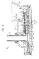
- FIG. 1 is a view showing a cross section of an upper casing part of a reheat steam turbine 100 of a first embodiment.
- the reheat steam turbine 100 includes a dual-structured casing composed of an inner casing 110 and an outer casing 111 provided outside the inner casing 110, and a heat chamber 112 is formed between the inner casing 110 and the outer casing 111.
- a turbine rotor 113 is penetratingly provided in the inner casing 110.
- nozzle diaphragm outer rings 117 are connected to an inner surface of the inner casing 110, and for example, nine-stages of nozzles 114 are provided.
- movingblades 115 are implanted in the turbine rotor 113 so as to correspond to these nozzles 114.
- This turbine rotor 113 is composed of: a high-temperature turbine rotor constituent part 113a positioned in an area extending from a nozzle 114a on a first stage (where steam temperature is 620°C or higher) to a moving blade 115a on a stage where the steam temperature becomes 550°C; and low-temperature turbine rotor constituent parts 113b connected to and sandwiching the high-temperature turbine rotor constituent part 113a.
- the high-temperature turbine rotor constituent part 113a and each of the low-temperature turbine rotor constituent parts 113b are connected by welding or bolting. The structure of a joint portion therebetween will be described later.
- the aforesaid inner casing 110 is composed of: a high-temperature casing constituent part110a covering the area where the high-temperature turbine rotor constituent part 113a is penetratingly provided; and low-temperature casing constituent parts 110b covering the areas where the low-temperature turbine rotor constituent parts 113b are penetratingly provided.
- the high-temperature casing constituent part 110a and each of the low-temperature casing constituent parts 110b are connected by welding or bolting, similarly to the aforesaid connection of the high-temperature turbine rotor constituent part 113a and each of the low-temperature turbine rotor constituent parts 113b.
- the high-temperature turbine rotor constituent part 113a and the high-temperature casing constituent part 110a positioned in the area extending from the nozzle 114a on the first stage to the moving blade 115a on the stage where the steam temperature becomes almost 550°C are exposed to high-temperature steam at 620°C or higher, which is an inlet steam temperature, and steam up to 550°C, and therefore are made of a corrosion and heat resistant material or the like whose mechanical strength (for example, a hundred thousand hour creep rupture strength) at high temperatures is high and which has steam oxidation resistance.
- the corrosion and heat resistant material for example, a Ni-based alloy is used, and concrete examples thereof are Inco625, Inco617, Inco713, and the like manufactured by Inco Limited.
- the nozzles 114, the nozzle diaphragm outer rings 117, nozzle diaphragm inner rings 118, the moving blades 115, and so on positioned in the area extending from the nozzle 114a on the first stage to the moving blade 115a on the stage where the steam temperature becomes 550°C are also made of the aforesaid corrosion and heat resistant material.
- the low-temperature turbine rotor constituent parts 113b and the low-temperature casing constituent parts 110b exposed to the steam at temperatures lower than 550°C are made of a material different from the aforesaid material forming the high-temperature turbine rotor constituent part 113a and the high-temperature casing constituent part 110a, and are preferably made of ferritic heat resistant steel or the like which has conventionally been in wide use as a material of a turbine rotor and a casing.
- this ferritic heat resistant steel are new 12Cr steel, modified 12Cr steel, 12Cr steel, 9Cr steel, CrMov Steel and the like but are not limited to these.
- nozzle labyrinths 119 are provided on turbine rotor 113 side surfaces of the nozzle diaphragm inner rings 118 to prevent leakage of the steam.
- the reheat steam turbine 100 further has a steam inlet pipe 130 which penetrates the outer casing 111 and the inner casing 110 and whose end portion communicates with and connected to a nozzle box 116 guiding the steam out to a moving blade side.
- These steam inlet pipe 130 and nozzle box 116 are exposed to the high-temperature steam at 620°C or hither which is the inlet steam temperature, and therefore are made of the aforesaid corrosion and heat resistant material.
- the nozzle box 116 may have a structure, for example, disclosed in JP-A No.
- FIG. 2 is a view showing part of a cross section of a joint portion between the high-temperature turbine rotor constituent part 113a and the low-temperature turbine rotor constituent part 113b which are connected by welding.
- FIG. 3 to FIG. 5 are views each showing part of a cross section of a joint portion between the high-temperature turbine rotor constituent part 113a and the low-temperature turbine rotor constituent part 113b which are connected by bolting.
- the high-temperature turbine rotor constituent part 113a and the low-temperature turbine rotor constituent part 113b are connected by welding on a downstream side of the nozzle 114 positioned on an immediate downstream side of the moving blade 115a on the stage where the steam temperature becomes 550°C, whereby a joint portion 120 is formed.
- flange portions 121, 122 protruding outward in a radial direction of the turbine rotor 113 are formed in joint end portions of the high-temperature turbine rotor constituent part 113a and the low-temperature turbine rotor constituent part 113b respectively, and the both flange portions 121, 122 are bolt-connected with a bolt 123 and a nut 124.
- the joint portion 120 by the bolt-connection is positioned on an upstream side of the nozzle 114 positioned on an immediate downstream side of the moving blade 115a on the stage where the steam temperature becomes 550°C.
- the joint portion by the bolt connection may be disposed to face the nozzle labyrinth 119.
- the bolt 123 and the nut 124 do not protrude in the axial direction of the turbine rotor 113 but are housed in a recessed portion formed by the protruding portions 121a, 122a, the turbine rotor 113, and the flange portions 121, 122.
- the protruding portions 121a, 122a it is possible to prevent scattering of the bolt 123 and the nut 124.
- connection of the high-temperature turbine rotor constituent part 113a and the low-temperature turbine rotor constituent part 113b in a joint portion 126 formed at a position corresponding to the nozzle 114a on the first stage can be realized by the above-described welding or bolting. In this case, it is also possible to obtain the same operation and effect as are obtained by the above-described welding or bolting.
- the steam whose temperature is 620°C or higher flowing into the nozzle box 116 in the reheat steam turbine 100 via the steam inlet pipe 130 passes through the steam channel between the nozzles 114 fixed to the inner casing 110 and the moving blades 115 implanted in the turbine rotor 113 to rotate the turbine rotor 113. Further, most of the steam having finished expansion work passes through a discharge path 125 to be discharged out of the reheat steam turbine 100 and flows into a boiler through, for example, a low-temperature reheating pipe.
- the above-described reheat steam turbine 100 may include a structure to introduce, as cooling steam, part of the steam having finished the expansion work to an area between the inner casing 110 and the outer casing 111 to cool the outer casing 111 and the inner casing 110.
- the cooling steam is discharged through a gland sealing part 127a or the discharge path 125.
- a method of introducing the cooling steam is not limited to this, and for example, steam extracted from a stage in the middle of the reheat steam turbine 100 or steam extracted from another steam turbine may be used as the cooling steam.
- the Ni-based alloy which is a corrosion and heat resistant material is used only in the high-temperature parts, in the turbine rotor 113 and the inner casing 110, whose temperature exceeds a tolerable temperature of a conventional material (for example, ferritic heat resistant steel) determined by mechanical strength and corrosion resistance, so that they can be driven with high-temperature steam at 620°C or higher to be able to maintain performances such as predetermined thermal efficiency, and they are also highly cost efficient.
- a conventional material for example, ferritic heat resistant steel
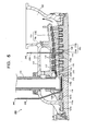
- FIG. 6 is a view showing a cross section of an upper casing part of a reheat steam turbine 200 of a second embodiment.
- the reheat steam turbine 200 of the second embodiment includes cooling parts to introduce cooling steam, in addition to the structure of the reheat steam turbine 100 of the first embodiment.
- the structure and materials except those of the cooling parts are the same as those of the reheat steamturbine 100 of the first embodiment, and therefore, the same reference numerals and symbols are used to designate the same constituent elements as those of the reheat steam turbine 100 of the first embodiment and they will be described only briefly or will not be repeatedly described.
- the reheat steam turbine 200 includes: a cooling steam supply pipe 220 disposed along a turbine rotor 113 and injecting cooling steam 240 from the vicinity of a joint portion 126 at a position corresponding to a nozzle 114a on a first stage to a wheel part 210 corresponding to a moving blade 115 on a first stage; and a cooling steam supply pipe 230 disposed between a moving blade 115a on a stage where steam temperature becomes 550°C and a nozzle 114 positioned on an immediate downstream side of the moving blade 115a and injecting the cooling steam 240 to the turbine rotor 113.
- cooling steam supply pipes 220, 230 function as the cooling parts, and the cooling steam 240 injected from these cooling steam supply pipes 220, 230 cool the turbine rotor 113, joint portions 120, 126, further, an outer casing 111, an inner casing 110, and so on.
- cooling steam 240 usable is, for example, steam extracted from a high-pressure turbine, a boiler, or the like, steam extracted from a stage in the middle of the reheat steam turbine 200, or steam discharged to a discharge path 125 of the reheat steam turbine 200, and its supply source is appropriately selected based on a set temperature of the cooling steam 240.
- FIG. 7 is a view showing part of a cross section of the joint portion between the high-temperature turbine rotor constituent part 113a and the low-temperature turbine rotor constituent part 113b which are connected by welding, and also showing the cooling part.
- FIG. 8 to FIG. 10 are views each showing part of a cross section of a joint portion between the high-temperature turbine rotor constituent part 113a and the low-temperature turbine rotor constituent part 113b which are connected by bolting, and also showing the cooling part.
- the high-temperature turbine rotor constituent part 113a and the low-temperature turbine rotor constituent part 113b are connected by welding on a downstream side of the nozzle 114 positioned on an immediate downstream side of the moving blade 115a on the stage where the steam temperature becomes 550°C, whereby the joint portion 120 is formed.
- the cooling steam supply pipe 230 is disposed between the moving blade 115a on the stage where the steam temperature becomes 550°C and the nozzle 114 positioned on the immediate downstream side of the moving blade 115a, and its steam injection port 230a is directed to the high-temperature turbine rotor constituent part 113a, being a predetermined distance apart from the high-temperature turbine rotor constituent part 113a.
- flange portions 121, 122 protruding outward in a radial direction of the turbine rotor 113 are formed in joint end portions of the high-temperature turbine rotor constituent part 113a and the low-temperature turbine rotor constituent part 113b respectively, and the both flange portions 121, 122 are bolt-connected with a bolt 123 and a nut 124.
- the cooling steam supply pipe 230 is disposed between the moving blade 115a on the stage where the steam temperature becomes 550°C and the flange portion 121 of the high-temperature turbine rotor constituent part 113a positioned on the immediate downstream side of the moving blade 115a, and its steam injection port 230a is directed to the high-temperature turbine rotor constituent part 113a, being a predetermined distance apart from the high-temperature turbine rotor constituent part 113a.
- the joint portion 120 by the bolt connection is positioned between the cooling steam supply pipe 230 and the nozzle 114 positioned on the downstream side of the moving blade 115a on the stage where the steam temperature becomes 550°C.
- FIG. 9 Another possible structure is, as shown in FIG. 9, that the joint portion by the bolt connection is disposed to face a nozzle labyrinth 119, and the cooling steam supply pipe 230 is positioned between the moving blade 115a on the stage where the steam temperature becomes 550°C and the flange portion 121 of the high-temperature turbine rotor constituent part 113a positioned on an immediate downstream side of the moving blade 115a.
- the joint portion it is possible to shorten the whole length of the turbine rotor 13 compared with the case of the bolt connection shown in FIG. 8.
- by supplying the cooling steam it is possible to prevent heat conduction to the low-temperature turbine rotor constituent part 113b side.
- protruding portions 121a, 122a protruding to a side different from the joint surface where the high-temperature turbine rotor constituent part 113a and the low-temperature turbine rotor constituent part 113b are joined and preventing the exposure of the bolt 123 and the nut 124 in the radial direction of the turbine rotor 113 may be provided along outer peripheral edges of the flange portions 121, 122 of the high-temperature turbine rotor constituent part 113a and the low-temperature turbine rotor constituent part 113b respectively.
- the bolt 12 and the nut 124 do not protrude in the axial direction of the turbine rotor 113 but are housed in a recessed portion formed by the protruding portions 121a, 122a, the turbine rotor 113, and the flange portions 121, 122.
- the protruding portions 121a, 122a it is possible to prevent scattering of the bolt 123 and the nut 124.
- the cooling steam supply pipe 220 is disposed along the turbine rotor 113, and its steam injection port 220a is positioned near the joint portion 126 at a position corresponding to the nozzle 114a on the first stage and is directed to the wheel part 210 corresponding to the moving blade 115 on the first stage. From this steam injection port 220a, the cooling steam 240 is injected toward the wheel part 210.
- the cooling steam 240 By thus supplying the cooling steam 240, it is possible to prevent heat conduction from the wheel part 210 corresponding to the moving blade 115a on the first stage where the high-temperature steam at 620°C or higher passes, to the low-temperature turbine rotor constituent part 113b side via the high-temperature turbine rotor constituent part 113a. Moreover, the cooling steam 240 also cools the joint portion 126 and its vicinity.
- the joint portion 126 at the position corresponding to the nozzle 114a on the first stage is formed by the weld connection as shown in FIG. 6 is described here, but the joint portion 126 may be formed by the bolt connection similarly to the above-described joint portion 120 on the downstream side.
- the cooling steam 240 is preferably supplied to an area between the joint portion 126 by the bolt connection and the wheel part 210 corresponding to the moving blade 115 on the first stage.
- the steam injection port 220a of the cooling steam supply pipe 220 is preferably directed to the wheel part 210 corresponding to the moving blade 115 on the first stage or the high-temperature turbine rotor constituent part 113a.
- the cooling steam 240 injected from the steam injection port 220a of the cooling steam supply pipe 220 collides with the wheel part 210 corresponding to the moving blade 115 on the first stage to cool the wheel part 210, and further comes into contact with the joint portion 126 to cool the joint portion 126 and its vicinity. Then, the cooling steam 240 passes through the gland sealing part 127b, and part thereof flows between the outer casing 111 and the inner casing 110 to cool the both casings. Further, the cooling steam 240 is introduced into a heat chamber 112 to be discharged through the discharge path 125. On the other hand, the rest of the cooling steam 240 having passed through the gland sealing part 127b passes through a gland sealing part 127a to be discharged.
- the cooling steam240 injected from the steam injection port 230a of the cooling steam supply pipe 230 collides with the high-temperature turbine rotor constituent part 113a on an immediate downstream side of the moving blade 115a on the stage where the steam temperature becomes 550°C and cools the high-temperature turbine rotor constituent part 113a. Subsequently, the cooling steam 240 flows downstream between the nozzle labyrinth 119 and the high-temperature turbine rotor constituent part 113a to cool the joint portion 120 and its vicinity.
- the cooling steam 240 injected from the steam injection port 230a of the cooling steam supply pipe 230 collides with the high-temperature turbine rotor constituent part 113a on the immediate downstream side of the moving blade 115a on the stage where the steam temperature becomes 550°C and cools the high-temperature turbine rotor constituent part 113a, and further cools the flange portions 121, 122 being the joint portion 120. Subsequently, the cooling steam 240 flows downstream between the nozzle labyrinth 119 and the low-temperature turbine rotor constituent part 113b while cooling the both.
- the cooling steam 240 injected from the steam injection port 230a of the cooling steam supply pipe 230 collides with the high-temperature turbine rotor constituent part 113a on the immediate downstream side of the moving blade 115a on the stage where the steam temperature becomes 550°C and cools the high-temperature turbine rotor constituent part 113a. Subsequently, the cooling steam 240 flows downstream between the nozzle labyrinth 119 and the flange portions 121, 122 to cool the flange portions 121, 122 being the joint portion 120.
- the cooling method by the cooling steam 240 injected from the steam injection port 220a of the cooling steam supply pipe 220 shown in FIG. 6 is a method to inject the cooling team 240 locally to the wheel part 210 near the joint portion 126 and can reduce a supply amount of the cooling steam 240 to a minimum. Consequently, blade cascade performance which becomes lower if the cooling steam 240 flows into a channel for a working steam from an area between the wheel parts 210 and the nozzle diaphragm inner rings 118 can be maintained at an equivalent level to that in a conventional steam turbine where the cooling steam is not supplied, and internal efficiency of the turbine itself can be improved.
- the steam injection port 220a of the cooling steam supply pipe 220 is directed to the wheel part 210 corresponding to the moving blade 115 on the first stage and is capable of spraying the cooling steam 240 at a predetermined velocity, resulting in improved heat conductivity, so that the high-temperature turbine rotor constituent part 113a can be effectively cooled.
- the cooling methods by the cooling steam 240 injected from the steam injection port 230a of the cooling steam supply pipe 230 shown in FIG. 7 to FIG. 10 are methods to inject the cooling steam 240 locally to the high-temperature turbine rotor constituent part 113a near the joint portion 120, and are capable of reducing a supply amount of the cooling steam 240 to a minimum. Consequently, blade cascade performance which becomes lower if the cooling steam 240 flows into the channel for the working steam from the area between the wheel parts 210 and the nozzle diaphragm inner rings 118 can be maintained at an equivalent level to that of a conventional steam turbine where the cooling steam is not supplied, and internal efficiency of the turbine itself can be improved.
- the steam injection port 230a of the cooling steam supply pipe 230 is directed to the high-temperature turbine rotor constituent part 113a and is capable of spraying the cooling steam 240 at a predetermined velocity, resulting in improved heat conductivity, so that the high-temperature turbine rotor constituent part 113a can be effectively cooled.
- the present invention has been concretely described based on the embodiments, but the present invention is not limited to these embodiments, and can be variously modified within a range not departing from the spirit of the present invention. Further, the steam turbine and the turbine rotor of the present invention are applicable to a steam turbine to which high-temperature steam at 620°C or higher is introduced.
Landscapes
- Engineering & Computer Science (AREA)
- Mechanical Engineering (AREA)
- General Engineering & Computer Science (AREA)
- Turbine Rotor Nozzle Sealing (AREA)
Abstract
Description
- This application is based upon and claims the benefit of priority from the prior
Japanese Patent Application No. 2006-121411, filed on April 26, 2006 - The present invention relates to a steam turbine and a turbine rotor, more particularly, to a steam turbine and a turbine rotor allowing the use of high-temperature steam at 620°C or higher.
- For most of high-temperature parts in thermal power generation facilities, ferritic heat resistant steels excellent in manufacturing performance and economic efficiency have been used. A steam turbine of such a conventional thermal power generation facility is generally under a steam temperature condition on order of not higher than 600°C, and therefore, its major components such as a turbine rotor and moving blades are made of ferritic heat resistant steel.
- However, in recent years, improvement in efficiency of thermal power generation facilities have been actively promoted from a viewpoint of environmental protection, and steam turbines utilizing high-temperature steam at about 600°C are operated. Such a steam turbine includes components requiring characteristics that cannot be satisfied by characteristics of the ferritic heat resistant steel, and therefore, these components are sometimes made of a heat resistant alloy or austenitic heat resistant steel more excellent in high-temperature resistance.
- For example,
JP-A 7-247806 JP-A2000-282808 Japanese Patent No. 3095745 JP-A 2000-282808 - Further, in view of global environmental protection, a need for higher efficiency enabling a reduction in emissions of CO2 SOx, and NOx is currently increasing. One of the most effective plans to enhance plant thermal efficiency in a thermal power generation facility is to increase steam temperature, and the development of a steam turbine on order of 700°C is under consideration.
- Further, for example,
JP-A 2004-353603 - In the development of the aforesaid steam turbine on order of 700°C, how strength of, in particular, turbine components can be ensured is currently groped for. In thermal power generation facilities, improved heat resistant steel has been conventionally used for turbine components such as a turbine rotor, nozzles, moving blades, a nozzle box (steam chamber), and a steam supply pipe included in a steam turbine, but when the temperature of reheated steam becomes 700°C or higher, it is difficult to maintain high level of strength guarantee of the turbine components.
- Under such circumstances, there is a demand for realizing a new art that is capable of maintaining high level of strength guarantee of turbine components even when conventional improved heat resistant steel is used as it is for the turbine components in a steam turbine. One prospective art to realize this is to use cooling steam for cooling the aforesaid turbine components. However, to cool a turbine rotor and a casing by the cooling steam in order to use the conventional material for portions, for instance, corresponding to and after a first-stage turbine, a required amount of the cooling steam amounts to several % of an amount of main steam. Moreover, since the cooling steam flows into a channel portion, there arises a problem of deterioration in internal efficiency of a turbine itself in accordance with deteriorationin blade cascade performance.
- The present invention was made to solve the above problems, and its object is to provide a steam turbine and a turbine rotor which can be driven by high-temperature steam to have improved thermal efficiency and which are excellent in economic efficiency, by using a corrosion and heat resistant material limitedly for predetermined turbine components.
- According to an aspect of the present invention, there is provided a steam turbine to which high-temperature steam at 620°C or higher is introduced, the steam turbine including a turbine rotor including: a high-temperature turbine rotor constituent part positioned in an area extending from a nozzle on a first stage to a moving blade on a stage where temperature of the steam becomes 550°C and made of a corrosion and heat resistant material; and low-temperature turbine rotor constituent parts connected to and sandwiching the high-temperature turbine rotor constituent part and made of a material different from the material of the high-temperature turbine rotor constituent part.
- According to another aspect of the present invention, there is provided a turbine rotor penetratingly provided in a steam turbine to which high-temperature steam at 620°C or higher is introduced, including: a high-temperature turbine rotor constituent part positioned in an area extending from a nozzle on a first stage in the steam turbine to a moving blade on a stage where temperature of the steam becomes 550°C and made of a corrosion and heat resistant material; and low-temperature turbine rotor constituent parts connected to and sandwiching the high-temperature turbine rotor constituent part and made of a material different from the material of the high-temperature turbine rotor constituent part.
- The present invention will be described with reference to the drawings, but these drawings are provided only for an illustrative purpose and in no way are intended to limit the present invention.
- FIG. 1 is a view showing a cross section of an upper casing part of a reheat steam turbine of a first embodiment.
- FIG. 2 is a view showing part of a cross section of a joint portion between a high-temperature turbine rotor constituent part and a low-temperature turbine rotor constituent part which are connected by welding.
- FIG. 3 is a view showing part of a cross section of a joint portion between the high-temperature turbine rotor constituent part and the low-temperature turbine rotor constituent part which are connected by bolting.
- FIG. 4 is a view showing part of a cross section of a joint portion between the high-temperature turbine rotor constituent part and the low-temperature turbine rotor constituent part which are connected by bolting.
- FIG. 5 is a view showing part of a cross section of a joint portion between the high-temperature turbine rotor constituent part and the low-temperature turbine rotor constituent part which are connected by bolting.
- FIG. 6 is a view showing a cross section of an upper casing part of a reheat steam turbine of a second embodiment.
- FIG. 7 is a view showing part of a cross section of a joint portion between a high-temperature turbine rotor constituent part and a low-temperature turbine rotor constituent part which are connected by welding, and also showing a cooling part.
- FIG. 8 is a view showing part of a cross section of a joint portion between the high-temperature turbine rotor constituent part and the low-temperature turbine rotor constituent part which are connected by bolting, and also showing the cooling part.
- FIG. 9 is a view showing part of a cross section of a joint portion between the high-temperature turbine rotor constituent part and the low-temperature turbine rotor constituent part which are connected by bolting, and also showing the cooling part.
- FIG. 10 is a view showing part of a cross section of a joint portion between the high-temperature turbine rotor constituent part and the low-temperature turbine rotor constituent part which are connected by bolting, and also showing the cooling part.
- Hereinafter, embodiments of the present invention will be described with reference to the drawings.
- FIG. 1 is a view showing a cross section of an upper casing part of a
reheat steam turbine 100 of a first embodiment. - As shown in FIG. 1, the
reheat steam turbine 100 includes a dual-structured casing composed of aninner casing 110 and anouter casing 111 provided outside theinner casing 110, and aheat chamber 112 is formed between theinner casing 110 and theouter casing 111. Aturbine rotor 113 is penetratingly provided in theinner casing 110. Further, nozzle diaphragmouter rings 117 are connected to an inner surface of theinner casing 110, and for example, nine-stages ofnozzles 114 are provided. Further,movingblades 115 are implanted in theturbine rotor 113 so as to correspond to thesenozzles 114. - This
turbine rotor 113 is composed of: a high-temperature turbinerotor constituent part 113a positioned in an area extending from anozzle 114a on a first stage (where steam temperature is 620°C or higher) to a movingblade 115a on a stage where the steam temperature becomes 550°C; and low-temperature turbinerotor constituent parts 113b connected to and sandwiching the high-temperature turbinerotor constituent part 113a. The high-temperature turbinerotor constituent part 113a and each of the low-temperature turbinerotor constituent parts 113b are connected by welding or bolting. The structure of a joint portion therebetween will be described later. Here, the aforesaidinner casing 110 is composed of: a high-temperature casing constituent part110a covering the area where the high-temperature turbinerotor constituent part 113a is penetratingly provided; and low-temperature casingconstituent parts 110b covering the areas where the low-temperature turbine rotorconstituent parts 113b are penetratingly provided. The high-temperature casingconstituent part 110a and each of the low-temperature casingconstituent parts 110b are connected by welding or bolting, similarly to the aforesaid connection of the high-temperature turbinerotor constituent part 113a and each of the low-temperature turbinerotor constituent parts 113b. - The high-temperature turbine
rotor constituent part 113a and the high-temperature casingconstituent part 110a positioned in the area extending from thenozzle 114a on the first stage to the movingblade 115a on the stage where the steam temperature becomes almost 550°C (strictly speaking, it may be a temperature near 550°C) are exposed to high-temperature steam at 620°C or higher, which is an inlet steam temperature, and steam up to 550°C, and therefore are made of a corrosion and heat resistant material or the like whose mechanical strength (for example, a hundred thousand hour creep rupture strength) at high temperatures is high and which has steam oxidation resistance. As the corrosion and heat resistant material, for example, a Ni-based alloy is used, and concrete examples thereof are Inco625, Inco617, Inco713, and the like manufactured by Inco Limited. Thenozzles 114, the nozzle diaphragmouter rings 117, nozzle diaphragminner rings 118, the movingblades 115, and so on positioned in the area extending from thenozzle 114a on the first stage to the movingblade 115a on the stage where the steam temperature becomes 550°C are also made of the aforesaid corrosion and heat resistant material. - The low-temperature turbine
rotor constituent parts 113b and the low-temperature casingconstituent parts 110b exposed to the steam at temperatures lower than 550°C are made of a material different from the aforesaid material forming the high-temperature turbinerotor constituent part 113a and the high-temperature casingconstituent part 110a, and are preferably made of ferritic heat resistant steel or the like which has conventionally been in wide use as a material of a turbine rotor and a casing. Concrete examples of this ferritic heat resistant steel are new 12Cr steel, modified 12Cr steel, 12Cr steel, 9Cr steel, CrMov Steel and the like but are not limited to these. - Further,
nozzle labyrinths 119 are provided onturbine rotor 113 side surfaces of the nozzle diaphragminner rings 118 to prevent leakage of the steam. - The
reheat steam turbine 100 further has asteam inlet pipe 130 which penetrates theouter casing 111 and theinner casing 110 and whose end portion communicates with and connected to anozzle box 116 guiding the steam out to a moving blade side. Thesesteam inlet pipe 130 andnozzle box 116 are exposed to the high-temperature steam at 620°C or hither which is the inlet steam temperature, and therefore are made of the aforesaid corrosion and heat resistant material. Here, thenozzle box 116 may have a structure, for example, disclosed inJP-A No. 2004-353603 - Next, the structure of the joint portion between the high-temperature turbine
rotor constituent part 113a and the low-temperature turbinerotor constituent part 113b will be described with reference to FIG. 2 to FIG. 5. - FIG. 2 is a view showing part of a cross section of a joint portion between the high-temperature turbine
rotor constituent part 113a and the low-temperature turbinerotor constituent part 113b which are connected by welding. Further, FIG. 3 to FIG. 5 are views each showing part of a cross section of a joint portion between the high-temperature turbinerotor constituent part 113a and the low-temperature turbinerotor constituent part 113b which are connected by bolting. - As shown in FIG. 2, the high-temperature turbine
rotor constituent part 113a and the low-temperature turbinerotor constituent part 113b are connected by welding on a downstream side of thenozzle 114 positioned on an immediate downstream side of the movingblade 115a on the stage where the steam temperature becomes 550°C, whereby ajoint portion 120 is formed. By thus connecting the high-temperature turbine rotorconstituent part 113a and the low-temperature turbine rotorconstituent part 113b by welding, it is possible to reduce an area occupied by thejoint portion 120 to a minimum. - Another possible structure is, as shown in FIG. 3, that
flange portions turbine rotor 113 are formed in joint end portions of the high-temperature turbine rotorconstituent part 113a and the low-temperature turbine rotorconstituent part 113b respectively, and the bothflange portions bolt 123 and anut 124. Thejoint portion 120 by the bolt-connection is positioned on an upstream side of thenozzle 114 positioned on an immediate downstream side of the movingblade 115a on the stage where the steam temperature becomes 550°C. By such bolt connection, it is possible to prevent thermal stress from occurring on a joint surface due to a difference in coefficient of linear expansion between the materials forming the high-temperature turbine rotorconstituent part 113a and the low-temperature turbine rotorconstituent part 113b. - Further, as shown in FIG. 4, the joint portion by the bolt connection may be disposed to face the
nozzle labyrinth 119. By thus positioning the joint portion, it is possible to shorten the whole length of theturbine rotor 113 compared with the case of the bolt connection shown in FIG. 3. - Further, as shown in FIG. 5, protruding
portions constituent part 113a and the low-temperature turbine rotorconstituent part 113b are joined and preventing the exposure of thebolt 123 and thenut 124 in the radial direction of theturbine rotor 113 may be provided along outer peripheral edges of theflange portions constituent part 113a and the low-temperature turbine rotorconstituent part 113b respectively. That is, thebolt 123 and thenut 124 do not protrude in the axial direction of theturbine rotor 113 but are housed in a recessed portion formed by the protrudingportions turbine rotor 113, and theflange portions portions bolt 123 and thenut 124. - Further, the connection of the high-temperature turbine rotor
constituent part 113a and the low-temperature turbine rotorconstituent part 113b in ajoint portion 126 formed at a position corresponding to thenozzle 114a on the first stage, though not shown, can be realized by the above-described welding or bolting. In this case, it is also possible to obtain the same operation and effect as are obtained by the above-described welding or bolting. - Next, the operation in the
reheat steam turbine 100 will be described with reference to FIG. 1. - The steam whose temperature is 620°C or higher flowing into the
nozzle box 116 in thereheat steam turbine 100 via thesteam inlet pipe 130 passes through the steam channel between thenozzles 114 fixed to theinner casing 110 and the movingblades 115 implanted in theturbine rotor 113 to rotate theturbine rotor 113. Further, most of the steam having finished expansion work passes through adischarge path 125 to be discharged out of thereheat steam turbine 100 and flows into a boiler through, for example, a low-temperature reheating pipe. - Incidentally, the above-described
reheat steam turbine 100 may include a structure to introduce, as cooling steam, part of the steam having finished the expansion work to an area between theinner casing 110 and theouter casing 111 to cool theouter casing 111 and theinner casing 110. In this case, the cooling steam is discharged through agland sealing part 127a or thedischarge path 125. It should be noted that a method of introducing the cooling steam is not limited to this, and for example, steam extracted from a stage in the middle of thereheat steam turbine 100 or steam extracted from another steam turbine may be used as the cooling steam. - As described above, according to the
reheat steam turbine 100 of the first embodiment and theturbine rotor 113 penetratingly provided in thereheat steam turbine 100, the Ni-based alloy which is a corrosion and heat resistant material is used only in the high-temperature parts, in theturbine rotor 113 and theinner casing 110, whose temperature exceeds a tolerable temperature of a conventional material (for example, ferritic heat resistant steel) determined by mechanical strength and corrosion resistance, so that they can be driven with high-temperature steam at 620°C or higher to be able to maintain performances such as predetermined thermal efficiency, and they are also highly cost efficient. - FIG. 6 is a view showing a cross section of an upper casing part of a
reheat steam turbine 200 of a second embodiment. Here, thereheat steam turbine 200 of the second embodiment includes cooling parts to introduce cooling steam, in addition to the structure of thereheat steam turbine 100 of the first embodiment. The structure and materials except those of the cooling parts are the same as those of thereheat steamturbine 100 of the first embodiment, and therefore, the same reference numerals and symbols are used to designate the same constituent elements as those of thereheat steam turbine 100 of the first embodiment and they will be described only briefly or will not be repeatedly described. - As shown in FIG. 6, the
reheat steam turbine 200 includes: a coolingsteam supply pipe 220 disposed along aturbine rotor 113 and injectingcooling steam 240 from the vicinity of ajoint portion 126 at a position corresponding to anozzle 114a on a first stage to awheel part 210 corresponding to a movingblade 115 on a first stage; and a coolingsteam supply pipe 230 disposed between a movingblade 115a on a stage where steam temperature becomes 550°C and anozzle 114 positioned on an immediate downstream side of the movingblade 115a and injecting the coolingsteam 240 to theturbine rotor 113. These coolingsteam supply pipes steam 240 injected from these coolingsteam supply pipes turbine rotor 113,joint portions outer casing 111, aninner casing 110, and so on. - As the cooling
steam 240, usable is, for example, steam extracted from a high-pressure turbine, a boiler, or the like, steam extracted from a stage in the middle of thereheat steam turbine 200, or steam discharged to adischarge path 125 of thereheat steam turbine 200, and its supply source is appropriately selected based on a set temperature of the coolingsteam 240. - Next, the structure of a joint portion between a high-temperature turbine rotor
constituent part 113a and a low-temperature turbine rotorconstituent part 113b will be described with reference to FIG. 7 to FIG. 10. - FIG. 7 is a view showing part of a cross section of the joint portion between the high-temperature turbine rotor
constituent part 113a and the low-temperature turbine rotorconstituent part 113b which are connected by welding, and also showing the cooling part. FIG. 8 to FIG. 10 are views each showing part of a cross section of a joint portion between the high-temperature turbine rotorconstituent part 113a and the low-temperature turbine rotorconstituent part 113b which are connected by bolting, and also showing the cooling part. - As shown in FIG. 7, the high-temperature turbine rotor
constituent part 113a and the low-temperature turbine rotorconstituent part 113b are connected by welding on a downstream side of thenozzle 114 positioned on an immediate downstream side of the movingblade 115a on the stage where the steam temperature becomes 550°C, whereby thejoint portion 120 is formed. Further, the coolingsteam supply pipe 230 is disposed between the movingblade 115a on the stage where the steam temperature becomes 550°C and thenozzle 114 positioned on the immediate downstream side of the movingblade 115a, and itssteam injection port 230a is directed to the high-temperature turbine rotorconstituent part 113a, being a predetermined distance apart from the high-temperature turbine rotorconstituent part 113a. - By thus connecting the high-temperature turbine rotor
constituent part 113a and the low-temperature turbine rotorconstituent part 113b by welding, it is possible to reduce an area occupied by thejoint portion 120 to a minimum. Further, by supplying the coolingsteam 240 to an area between the movingblade 115a on the stage where the steam temperature becomes 550°C and thenozzle 114 positioned on the immediate downstream side of the movingblade 115a, it is possible to cool thejoint portion 120 and the high-temperature turbine rotorconstituent part 113a near thejoint portion 120, so that it is possible to prevent the occurrence of thermal stress in thejoint portion 120 and heat conduction to the low-temperature turbine rotorconstituent part 113b side. - Another possible structure is, as shown in FIG. 8, that
flange portions turbine rotor 113 are formed in joint end portions of the high-temperature turbine rotorconstituent part 113a and the low-temperature turbine rotorconstituent part 113b respectively, and the bothflange portions bolt 123 and anut 124. The coolingsteam supply pipe 230 is disposed between the movingblade 115a on the stage where the steam temperature becomes 550°C and theflange portion 121 of the high-temperature turbine rotorconstituent part 113a positioned on the immediate downstream side of the movingblade 115a, and itssteam injection port 230a is directed to the high-temperature turbine rotorconstituent part 113a, being a predetermined distance apart from the high-temperature turbine rotorconstituent part 113a. Further, thejoint portion 120 by the bolt connection is positioned between the coolingsteam supply pipe 230 and thenozzle 114 positioned on the downstream side of the movingblade 115a on the stage where the steam temperature becomes 550°C. - By such bolt connection and the supply of the cooling
steam 240, it is possible to prevent thermal stress from occurring in a joint surface due to a difference in coefficient of linear expansion between materials forming the high-temperature turbine rotorconstituent part 113a and the low-temperature turbine rotorconstituent part 113b. Further, by supplying the cooling steam, it is possible to prevent heat conduction to the low-temperature turbine rotorconstituent part 113b side. - Another possible structure is, as shown in FIG. 9, that the joint portion by the bolt connection is disposed to face a
nozzle labyrinth 119, and the coolingsteam supply pipe 230 is positioned between the movingblade 115a on the stage where the steam temperature becomes 550°C and theflange portion 121 of the high-temperature turbine rotorconstituent part 113a positioned on an immediate downstream side of the movingblade 115a. By thus positioning the joint portion, it is possible to shorten the whole length of the turbine rotor 13 compared with the case of the bolt connection shown in FIG. 8. Moreover, by supplying the cooling steam, it is possible to prevent heat conduction to the low-temperature turbine rotorconstituent part 113b side. - Further, as shown in FIG. 10, protruding
portions constituent part 113a and the low-temperature turbine rotorconstituent part 113b are joined and preventing the exposure of thebolt 123 and thenut 124 in the radial direction of theturbine rotor 113 may be provided along outer peripheral edges of theflange portions constituent part 113a and the low-temperature turbine rotorconstituent part 113b respectively. That is, the bolt 12 and thenut 124 do not protrude in the axial direction of theturbine rotor 113 but are housed in a recessed portion formed by the protrudingportions turbine rotor 113, and theflange portions portions bolt 123 and thenut 124. - Further, as shown in FIG. 6, the cooling
steam supply pipe 220 is disposed along theturbine rotor 113, and itssteam injection port 220a is positioned near thejoint portion 126 at a position corresponding to thenozzle 114a on the first stage and is directed to thewheel part 210 corresponding to the movingblade 115 on the first stage. From thissteam injection port 220a, the coolingsteam 240 is injected toward thewheel part 210. - By thus supplying the cooling
steam 240, it is possible to prevent heat conduction from thewheel part 210 corresponding to the movingblade 115a on the first stage where the high-temperature steam at 620°C or higher passes, to the low-temperature turbine rotorconstituent part 113b side via the high-temperature turbine rotorconstituent part 113a. Moreover, the coolingsteam 240 also cools thejoint portion 126 and its vicinity. - Incidentally, the structure where the
joint portion 126 at the position corresponding to thenozzle 114a on the first stage is formed by the weld connection as shown in FIG. 6 is described here, but thejoint portion 126 may be formed by the bolt connection similarly to the above-describedjoint portion 120 on the downstream side. In this case, the coolingsteam 240 is preferably supplied to an area between thejoint portion 126 by the bolt connection and thewheel part 210 corresponding to the movingblade 115 on the first stage. At this time, thesteam injection port 220a of the coolingsteam supply pipe 220 is preferably directed to thewheel part 210 corresponding to the movingblade 115 on the first stage or the high-temperature turbine rotorconstituent part 113a. - Here, the behavior of the cooling
steam 240 will be described. - First, the cooling
steam 240 injected from thesteam injection port 220a of the coolingsteam supply pipe 220 will be described with reference to FIG. 6. - The cooling
steam 240 injected from thesteam injection port 220a of the coolingsteam supply pipe 220 collides with thewheel part 210 corresponding to the movingblade 115 on the first stage to cool thewheel part 210, and further comes into contact with thejoint portion 126 to cool thejoint portion 126 and its vicinity. Then, the coolingsteam 240 passes through thegland sealing part 127b, and part thereof flows between theouter casing 111 and theinner casing 110 to cool the both casings. Further, the coolingsteam 240 is introduced into aheat chamber 112 to be discharged through thedischarge path 125. On the other hand, the rest of the coolingsteam 240 having passed through thegland sealing part 127b passes through agland sealing part 127a to be discharged. - Next, the cooling
steam 240 injected from thesteam injection port 230a of the coolingsteam supply pipe 230 will be described with reference to FIG. 7 to FIG. 10. - In the structure shown in FIG. 7, the cooling steam240 injected from the
steam injection port 230a of the coolingsteam supply pipe 230 collides with the high-temperature turbine rotorconstituent part 113a on an immediate downstream side of the movingblade 115a on the stage where the steam temperature becomes 550°C and cools the high-temperature turbine rotorconstituent part 113a. Subsequently, the coolingsteam 240 flows downstream between thenozzle labyrinth 119 and the high-temperature turbine rotorconstituent part 113a to cool thejoint portion 120 and its vicinity. - In the structure shown in FIG. 8, the cooling
steam 240 injected from thesteam injection port 230a of the coolingsteam supply pipe 230 collides with the high-temperature turbine rotorconstituent part 113a on the immediate downstream side of the movingblade 115a on the stage where the steam temperature becomes 550°C and cools the high-temperature turbine rotorconstituent part 113a, and further cools theflange portions joint portion 120. Subsequently, the coolingsteam 240 flows downstream between thenozzle labyrinth 119 and the low-temperature turbine rotorconstituent part 113b while cooling the both. - In the structures shown in FIG. 9 and FIG. 10, the cooling
steam 240 injected from thesteam injection port 230a of the coolingsteam supply pipe 230 collides with the high-temperature turbine rotorconstituent part 113a on the immediate downstream side of the movingblade 115a on the stage where the steam temperature becomes 550°C and cools the high-temperature turbine rotorconstituent part 113a. Subsequently, the coolingsteam 240 flows downstream between thenozzle labyrinth 119 and theflange portions flange portions joint portion 120. - As described above, the cooling method by the cooling
steam 240 injected from thesteam injection port 220a of the coolingsteam supply pipe 220 shown in FIG. 6 is a method to inject thecooling team 240 locally to thewheel part 210 near thejoint portion 126 and can reduce a supply amount of the coolingsteam 240 to a minimum. Consequently, blade cascade performance which becomes lower if the coolingsteam 240 flows into a channel for a working steam from an area between thewheel parts 210 and the nozzle diaphragminner rings 118 can be maintained at an equivalent level to that in a conventional steam turbine where the cooling steam is not supplied, and internal efficiency of the turbine itself can be improved. Further, it is also possible to cool theouter casing 111, theinner casing 110, and so on by the coolingsteam 240 which has passed through thegland sealing part 127b. Further, thesteam injection port 220a of the coolingsteam supply pipe 220 is directed to thewheel part 210 corresponding to the movingblade 115 on the first stage and is capable of spraying the coolingsteam 240 at a predetermined velocity, resulting in improved heat conductivity, so that the high-temperature turbine rotorconstituent part 113a can be effectively cooled. - Further, as described above, the cooling methods by the cooling
steam 240 injected from thesteam injection port 230a of the coolingsteam supply pipe 230 shown in FIG. 7 to FIG. 10 are methods to inject the coolingsteam 240 locally to the high-temperature turbine rotorconstituent part 113a near thejoint portion 120, and are capable of reducing a supply amount of the coolingsteam 240 to a minimum. Consequently, blade cascade performance which becomes lower if the coolingsteam 240 flows into the channel for the working steam from the area between thewheel parts 210 and the nozzle diaphragminner rings 118 can be maintained at an equivalent level to that of a conventional steam turbine where the cooling steam is not supplied, and internal efficiency of the turbine itself can be improved. Further, thesteam injection port 230a of the coolingsteam supply pipe 230 is directed to the high-temperature turbine rotorconstituent part 113a and is capable of spraying the coolingsteam 240 at a predetermined velocity, resulting in improved heat conductivity, so that the high-temperature turbine rotorconstituent part 113a can be effectively cooled. - Hitherto, the present invention has been concretely described based on the embodiments, but the present invention is not limited to these embodiments, and can be variously modified within a range not departing from the spirit of the present invention. Further, the steam turbine and the turbine rotor of the present invention are applicable to a steam turbine to which high-temperature steam at 620°C or higher is introduced.
- It is explicitly stated that all features disclosed in the description and/or the claims are intended to be disclosed separately and independently from each other for the purpose of original disclosure as well as for the purpose of restricting the claimed invention independent of the composition of the features in the embodiments and/or the claims. It is explicitly stated that all value ranges or indications of groups of entities disclose every possible intermediate value or intermediate entity for the purpose of original disclosure as well as for the purpose of restricting the claimed invention, in particular as limits of value ranges.
Claims (15)
- Asteamturbine (100, 200) to which high-temperature steam at 620°C or higher is introduced and which includes a turbine rotor (113), characterized in that the turbine rotor (113) comprises:a high-temperature turbine rotor constituent part (113a) positioned in an area extending from a nozzle (114a) on a first stage to a moving blade (115a) on a stage where temperature of the steam becomes 550°C and made of a corrosion and heat resistant material; andlow-temperature turbine rotor constituent parts (113b) connected to and sandwiching the high-temperature turbine rotor constituent part (113a) and made of a material different from the material of the high-temperature turbine rotor constituent part (113a).
- The steam turbine (100, 200) according to claim 1, characterized in that
the corrosion and heat resistant material forming the high-temperature turbine rotor constituent part (113a) is a Ni-based alloy, and the material forming the low-temperature turbine rotor constituent parts (113b) is ferritic heat resistant steel. - The steam turbine (100, 200) according to claim 1 or claim 2,
wherein the high-temperature turbine rotor constituent part (113a)and thelow-temperature turbine rotor constituent parts(113b) are connected by welding or bolting. - The steam turbine (100, 200) according to claim 3, characterized in that
in a case where the high-temperature turbine rotor constituent part (113a) and each of the low-temperature turbine rotor constituent parts (113b) are connected by the bolting, flange portions (121, 122) formed in joint end portions of the high-temperature turbine rotor constituent part (113a) and the low-temperature turbine rotor constituent part (113b) to protrude outward in a radial direction of the turbine rotor (113) are bolted. - The steam turbine (100, 200) according to claim 4, characterized in that
along outer peripheral edges of the flange portions (121, 122) formed in the joint end portions of the high-temperature turbine rotor constituent part (113a) and the low-temperature turbine rotor constituentpart (113b), protruding portions (121a,122a) protruding to a side different from a joint surface between the high-temperature turbine rotor constituent part (113a) and the low-temperature turbine rotor constituent part (113b) and preventing a bolting member (123, 124) from being exposed in the radial direction are formed. - The steam turbine (100, 200) according to any one of claim 1 to claim 5, characterized in that
a joint portion (126) on an upstream side out of joint portions (120, 126) where the high-temperature turbine rotor constituent part (113a) and the low-temperature turbine rotor constituent parts (113b) are connected is formed at a position corresponding to the nozzle (114a) on the first stage, and a joint portion (120) on a downstream side is formed at a position on an upstream side of, at a position facing a labyrinth part (119) corresponding to, or at a position on a downstream side of a nozzle (114) positioned on an immediate downstream side of the moving blade (115a) on the stage where temperature of the steam becomes 550°C. - The steam turbine (100, 200) according to any one of claim 1 to claim 6, characterized in that
in a casing (110) of the steam turbine (100, 200) connected to a nozzle diaphragm (117), a constituent portion (110a) covering the area in which the high-temperature turbine rotor constituent part (113a) is penetratingly provided is made of a corrosion and heat resistant material. - The steam turbine (100, 200) according to any one of claim 1 to claim 7, characterized in that
the steam turbine (100, 200) further comprises cooling parts (220, 230) cooling, by cooling steam (240), joint portions (120, 126) where the high-temperature turbine rotor constituent part (113a) and the low-temperature turbine rotor constituent parts (113b) are connected to each other. - The steam turbine (100, 200) according to claim 8, characterized in that
the cooling part (230) cooling a joint portion (120) on a downstream side out of the joint portions (120, 126) where the high-temperature turbine rotor constituent part (113a) and the low-temperature turbine rotor constituent parts (113b) are connected to each other supplies the cooling steam (240) to an upstream side of a nozzle (114) positioned on an immediate downstream side of the moving blade (115a) on the stage where the steam temperature becomes 550°C. - A turbine rotor (113) penetratingly provided in a steam turbine (100, 200) to which high-temperature steam at 620°C or higher is introduced, characterized in that the turbine rotor (113) comprises:a high-temperature turbine rotor constituent part (113a) positioned in an area extending from a nozzle (114a) on a first stage in the steam turbine (100, 200) to a moving blade (115a) on a stage where temperature of the steam becomes 550°C and made of a corrosion and heat resistant material; andlow-temperature turbine rotor constituent parts (113b) connected to and sandwiching the high-temperature turbine rotor constituent part (113a) and made of a material different from the material of the high-temperature turbine rotor constituent part (113a) .
- The turbine rotor (113) according to claim 10, characterized in that
the corrosion and heat resistant material forming the high-temperature turbine rotor constituent part (113a) is a Ni-based alloy, and the material forming the low-temperature turbine rotor constituent parts (113b) is ferritic heat resistant steel. - The turbine rotor (113) according to claim 10 or claim 11, characterized in that
the high-temperature turbine rotor constituent part (113a) and the low-temperature turbine rotor constituent parts (113b) are connected by welding or bolting. - The turbine rotor (113) according to claim 12, characterized in that
in a case where the high-temperature turbine rotor constituent part (113a) and each of the low-temperature turbine rotor constituent parts (113b) are connected by the bolting, flange portions (121, 122) formed in joint end portions of the high-temperature turbine rotor constituent part (113a) and the low-temperature turbine rotor constituent part (113b) to protrude outward in a radial direction of the turbine rotor (113) are bolted. - The turbine rotor (113) according to claim 13, characterized in that
along outer peripheral edges of the flange portions (121, 122) formed in the joint end portions of the high-temperature turbine rotor constituent part (113a) and the low-temperature turbine rotor constituent part (113b),protruding portions(121a,122a)protruding to a side different from a joint surface between the high-temperature turbine rotor constituent part (113a) and the low-temperature turbine rotor part (113b)and preventing a bolting member (123, 124) from being exposed in the radial direction are formed. - The turbine rotor (113) according to any one of claim 10 to claim 14, characterized in that
a joint portion (126) on an upstream side out of joint portions (120, 126) where the high-temperature turbine rotor constituent part (113a)and the low-temperature turbine rotor constituent parts(113b) are connected is formed at a position corresponding to the nozzle (114a) on the first stage in the steam turbine (100, 200), and a joint portion (120) on a downstream side is formed at a position on an upstream side of, at a position facing a labyrinth part (119) corresponding to, or at a position on a downstream side of a nozzle (114) positioned on an immediate downstream side of the moving blade (115a) on the stage where temperature of the steam becomes 550°C.
Applications Claiming Priority (1)
| Application Number | Priority Date | Filing Date | Title |
|---|---|---|---|
| JP2006121411A JP2007291966A (en) | 2006-04-26 | 2006-04-26 | Steam turbine and turbine rotor |
Publications (3)
| Publication Number | Publication Date |
|---|---|
| EP1849959A2 true EP1849959A2 (en) | 2007-10-31 |
| EP1849959A3 EP1849959A3 (en) | 2009-12-23 |
| EP1849959B1 EP1849959B1 (en) | 2011-08-03 |
Family
ID=38283295
Family Applications (1)
| Application Number | Title | Priority Date | Filing Date |
|---|---|---|---|
| EP07008143A Not-in-force EP1849959B1 (en) | 2006-04-26 | 2007-04-20 | Steam turbine and turbine rotor |
Country Status (4)
| Country | Link |
|---|---|
| US (1) | US7850423B2 (en) |
| EP (1) | EP1849959B1 (en) |
| JP (1) | JP2007291966A (en) |
| CN (1) | CN101063414B (en) |
Cited By (3)
| Publication number | Priority date | Publication date | Assignee | Title |
|---|---|---|---|---|
| EP2151547A2 (en) | 2008-08-07 | 2010-02-10 | Kabushiki Kaisha Toshiba | Steam turbine and steam turbine plant system |
| EP2354450A2 (en) * | 2010-02-02 | 2011-08-10 | General Electric Company | Rotor wheel capable of carrying multiple blade stages |
| EP2597271A4 (en) * | 2010-07-14 | 2017-05-31 | Mitsubishi Hitachi Power Systems, Ltd. | Combined cycle power generator |
Families Citing this family (19)
| Publication number | Priority date | Publication date | Assignee | Title |
|---|---|---|---|---|
| JP5049578B2 (en) | 2006-12-15 | 2012-10-17 | 株式会社東芝 | Steam turbine |
| EP2182086B1 (en) | 2008-06-18 | 2016-09-21 | Mitsubishi Hitachi Power Systems, Ltd. | Process for producing a ni-base alloy-high chromium steel structure |
| CN101765702B (en) | 2008-06-18 | 2013-05-15 | 三菱重工业株式会社 | Rotor of rotary machine and method for manufacturing same |
| JP2011069307A (en) * | 2009-09-28 | 2011-04-07 | Hitachi Ltd | Steam turbine rotor and steam turbine using the same |
| KR101353840B1 (en) * | 2009-12-21 | 2014-01-20 | 미츠비시 쥬고교 가부시키가이샤 | Cooling method and device in single-flow turbine |
| JP5618701B2 (en) * | 2010-08-24 | 2014-11-05 | 株式会社東芝 | Steam turbine turbine rotor and steam turbine |
| JP2012077702A (en) * | 2010-10-04 | 2012-04-19 | Toshiba Corp | Steam turbine rotor, method of manufacturing the same, and steam turbine |
| US20120177494A1 (en) * | 2011-01-06 | 2012-07-12 | General Electric Company | Steam turbine rotor with mechanically coupled high and low temperature sections using different materials |
| US8944761B2 (en) * | 2011-01-21 | 2015-02-03 | General Electric Company | Welded rotor, a steam turbine having a welded rotor and a method for producing a welded rotor |
| US20120189459A1 (en) * | 2011-01-21 | 2012-07-26 | General Electric Company | Welded Rotor, a Steam Turbine having a Welded Rotor and a Method for Producing a Welded Rotor |
| US20130017092A1 (en) * | 2011-07-11 | 2013-01-17 | General Electric Company | Rotor assembly for gas turbines |
| US20130177438A1 (en) * | 2012-01-06 | 2013-07-11 | General Electric Company | Sectioned rotor, a steam turbine having a sectioned rotor and a method for producing a sectioned rotor |
| US9039365B2 (en) | 2012-01-06 | 2015-05-26 | General Electric Company | Rotor, a steam turbine and a method for producing a rotor |
| CN104060192B (en) * | 2014-06-27 | 2015-12-30 | 南京赛达机械制造有限公司 | A kind of turbine blade and production technique thereof improving water erosion resistent ability |
| CN104032239B (en) * | 2014-06-27 | 2016-02-10 | 南京赛达机械制造有限公司 | A kind of corrosion-resistant turbine blade and production technique thereof |
| CN104481618B (en) * | 2014-11-14 | 2017-02-01 | 东方电气集团东方汽轮机有限公司 | High-parameter ultra-supercritical steam turbine generator unit |
| CN105351011B (en) * | 2015-11-26 | 2017-03-29 | 北京全三维能源科技股份有限公司 | Steam turbine and its pin combined rotor, the assemble method of combined rotor |
| CN105317465B (en) * | 2015-11-26 | 2017-04-12 | 北京全三维能源科技股份有限公司 | Steam turbine and bolt combination rotor thereof and assembly method of combination rotor |
| JP2020097894A (en) * | 2018-12-17 | 2020-06-25 | 東芝エネルギーシステムズ株式会社 | Turbine cabin |
Family Cites Families (17)
| Publication number | Priority date | Publication date | Assignee | Title |
|---|---|---|---|---|
| JPS5817322B2 (en) * | 1977-10-31 | 1983-04-06 | 三井造船株式会社 | Axial coupling structure of gas turbine rotor |
| JPS5968501A (en) * | 1982-10-13 | 1984-04-18 | Hitachi Ltd | Method and device for cooling steam turbine rotor |
| US5257905A (en) * | 1992-05-08 | 1993-11-02 | Westinghouse Electric Corp. | Rotor coupling anti-windage apparatus |
| JP3582848B2 (en) | 1994-03-14 | 2004-10-27 | 株式会社東芝 | Steam turbine power plant |
| JP2948324B2 (en) * | 1995-04-12 | 1999-09-13 | 三菱重工業株式会社 | High-strength, high-toughness heat-resistant steel |
| US6358004B1 (en) * | 1996-02-16 | 2002-03-19 | Hitachi, Ltd. | Steam turbine power-generation plant and steam turbine |
| JP3999402B2 (en) * | 1998-06-09 | 2007-10-31 | 三菱重工業株式会社 | Dissimilar welding rotor for steam turbine |
| JP2000282808A (en) * | 1999-03-26 | 2000-10-10 | Toshiba Corp | Steam turbine equipment |
| JP3975609B2 (en) * | 1999-04-01 | 2007-09-12 | 株式会社日立製作所 | gas turbine |
| JP3095745B1 (en) | 1999-09-09 | 2000-10-10 | 三菱重工業株式会社 | Ultra high temperature power generation system |
| DE50208002D1 (en) * | 2002-07-01 | 2006-10-12 | Alstom Technology Ltd | Rotor for a rotary thermal machine and method for producing such a rotor |
| EP1473442B1 (en) | 2003-04-30 | 2014-04-23 | Kabushiki Kaisha Toshiba | Steam turbine, steam turbine plant and method of operating a steam turbine in a steam turbine plant |
| US6994519B2 (en) | 2003-05-20 | 2006-02-07 | General Electric Company | Apparatus and methods for coupling axially aligned turbine rotors |
| CN1573018B (en) | 2003-05-20 | 2010-09-15 | 株式会社东芝 | Steam turbine |
| JP4304006B2 (en) | 2003-05-30 | 2009-07-29 | 株式会社東芝 | Steam turbine |
| DE10355738A1 (en) | 2003-11-28 | 2005-06-16 | Alstom Technology Ltd | Rotor for a turbine |
| EP1577494A1 (en) | 2004-03-17 | 2005-09-21 | Siemens Aktiengesellschaft | Welded steam turbine shaft and its method of manufacture |
-
2006
- 2006-04-26 JP JP2006121411A patent/JP2007291966A/en active Pending
-
2007
- 2007-04-20 EP EP07008143A patent/EP1849959B1/en not_active Not-in-force
- 2007-04-24 US US11/739,358 patent/US7850423B2/en not_active Expired - Fee Related
- 2007-04-25 CN CN2007101018290A patent/CN101063414B/en not_active Expired - Fee Related
Non-Patent Citations (1)
| Title |
|---|
| None |
Cited By (4)
| Publication number | Priority date | Publication date | Assignee | Title |
|---|---|---|---|---|
| EP2151547A2 (en) | 2008-08-07 | 2010-02-10 | Kabushiki Kaisha Toshiba | Steam turbine and steam turbine plant system |
| EP2151547A3 (en) * | 2008-08-07 | 2013-04-03 | Kabushiki Kaisha Toshiba | Steam turbine and steam turbine plant system |
| EP2354450A2 (en) * | 2010-02-02 | 2011-08-10 | General Electric Company | Rotor wheel capable of carrying multiple blade stages |
| EP2597271A4 (en) * | 2010-07-14 | 2017-05-31 | Mitsubishi Hitachi Power Systems, Ltd. | Combined cycle power generator |
Also Published As
| Publication number | Publication date |
|---|---|
| US20070253812A1 (en) | 2007-11-01 |
| JP2007291966A (en) | 2007-11-08 |
| EP1849959A3 (en) | 2009-12-23 |
| US7850423B2 (en) | 2010-12-14 |
| CN101063414B (en) | 2012-08-29 |
| CN101063414A (en) | 2007-10-31 |
| EP1849959B1 (en) | 2011-08-03 |
Similar Documents
| Publication | Publication Date | Title |
|---|---|---|
| EP1849959B1 (en) | Steam turbine and turbine rotor | |
| US8277173B2 (en) | Turbine rotor and steam turbine | |
| AU2007214378B2 (en) | Methods and apparatus for fabricating turbine engines | |
| CN101220757B (en) | Steam turbine | |
| US8454303B2 (en) | Turbine nozzle assembly | |
| US8162598B2 (en) | Gas turbine sealing apparatus | |
| EP2483529B1 (en) | Gas turbine nozzle arrangement and gas turbine | |
| US7836702B2 (en) | Gas turbine combustor exit duct and HP vane interface | |
| US7201559B2 (en) | Stationary ring assembly for a gas turbine | |
| EP2984296A1 (en) | Blade outer air seal with secondary air sealing | |
| US12624644B2 (en) | Seal assembly for a rotary machine | |
| US20150098808A1 (en) | Method and system to facilitate sealing in gas turbines | |
| CN113250766B (en) | Hot gas path components including the rear exhaust pipe and rear flange | |
| US10280777B2 (en) | System and method including a circumferential seal assembly to facilitate sealing in a turbine | |
| US10563529B2 (en) | Turbine and turbine stator blade | |
| KR102048874B1 (en) | Turbine vane having improved flexibility | |
| EP2613009A2 (en) | Turbine assembly and method for reducing fluid flow between turbine components | |
| EP2685052A1 (en) | A heat shield and a method for construction thereof | |
| JP2009127515A (en) | High temperature steam turbine | |
| KR101353840B1 (en) | Cooling method and device in single-flow turbine | |
| Marshall et al. | Detailed design and cost estimation of a 300 MWE oxy-fuel sCO2 turbine | |
| US11300209B2 (en) | Wire mesh brush seal windage cover | |
| Hawley et al. | Significant Performance Improvements of GE-Built, Frame No. 7, Model EA, GT | |
| WO2017029689A1 (en) | Axial-flow turbine | |
| JP2016006299A (en) | Sealing structure and rotor assembly |
Legal Events
| Date | Code | Title | Description |
|---|---|---|---|
| PUAI | Public reference made under article 153(3) epc to a published international application that has entered the european phase |
Free format text: ORIGINAL CODE: 0009012 |
|
| 17P | Request for examination filed |
Effective date: 20070420 |
|
| AK | Designated contracting states |
Kind code of ref document: A2 Designated state(s): AT BE BG CH CY CZ DE DK EE ES FI FR GB GR HU IE IS IT LI LT LU LV MC MT NL PL PT RO SE SI SK TR |
|
| AX | Request for extension of the european patent |
Extension state: AL BA HR MK YU |
|
| PUAL | Search report despatched |
Free format text: ORIGINAL CODE: 0009013 |
|
| AK | Designated contracting states |
Kind code of ref document: A3 Designated state(s): AT BE BG CH CY CZ DE DK EE ES FI FR GB GR HU IE IS IT LI LT LU LV MC MT NL PL PT RO SE SI SK TR |
|
| AX | Request for extension of the european patent |
Extension state: AL BA HR MK RS |
|
| 17Q | First examination report despatched |
Effective date: 20100310 |
|
| GRAP | Despatch of communication of intention to grant a patent |
Free format text: ORIGINAL CODE: EPIDOSNIGR1 |
|
| AKX | Designation fees paid |
Designated state(s): DE FR |
|
| GRAS | Grant fee paid |
Free format text: ORIGINAL CODE: EPIDOSNIGR3 |
|
| RBV | Designated contracting states (corrected) |
Designated state(s): CH DE FR LI |
|
| GRAA | (expected) grant |
Free format text: ORIGINAL CODE: 0009210 |
|
| AK | Designated contracting states |
Kind code of ref document: B1 Designated state(s): CH DE FR LI |
|
| REG | Reference to a national code |
Ref country code: CH Ref legal event code: EP |
|
| REG | Reference to a national code |
Ref country code: CH Ref legal event code: NV Representative=s name: E. BLUM & CO. AG PATENT- UND MARKENANWAELTE VSP |
|
| REG | Reference to a national code |
Ref country code: DE Ref legal event code: R096 Ref document number: 602007016198 Country of ref document: DE Effective date: 20110929 |
|
| PLBE | No opposition filed within time limit |
Free format text: ORIGINAL CODE: 0009261 |
|
| STAA | Information on the status of an ep patent application or granted ep patent |
Free format text: STATUS: NO OPPOSITION FILED WITHIN TIME LIMIT |
|
| 26N | No opposition filed |
Effective date: 20120504 |
|
| REG | Reference to a national code |
Ref country code: DE Ref legal event code: R097 Ref document number: 602007016198 Country of ref document: DE Effective date: 20120504 |
|
| REG | Reference to a national code |
Ref country code: FR Ref legal event code: ST Effective date: 20121228 |
|
| PG25 | Lapsed in a contracting state [announced via postgrant information from national office to epo] |
Ref country code: FR Free format text: LAPSE BECAUSE OF NON-PAYMENT OF DUE FEES Effective date: 20120430 |
|
| PGFP | Annual fee paid to national office [announced via postgrant information from national office to epo] |
Ref country code: DE Payment date: 20160412 Year of fee payment: 10 Ref country code: CH Payment date: 20160411 Year of fee payment: 10 |
|
| REG | Reference to a national code |
Ref country code: DE Ref legal event code: R119 Ref document number: 602007016198 Country of ref document: DE |
|
| REG | Reference to a national code |
Ref country code: CH Ref legal event code: PL |
|
| PG25 | Lapsed in a contracting state [announced via postgrant information from national office to epo] |
Ref country code: DE Free format text: LAPSE BECAUSE OF NON-PAYMENT OF DUE FEES Effective date: 20171103 |
|
| PG25 | Lapsed in a contracting state [announced via postgrant information from national office to epo] |
Ref country code: LI Free format text: LAPSE BECAUSE OF NON-PAYMENT OF DUE FEES Effective date: 20170430 Ref country code: CH Free format text: LAPSE BECAUSE OF NON-PAYMENT OF DUE FEES Effective date: 20170430 |