EP1849906A1 - Integrated tub overflow system for top-loading washing machine - Google Patents
Integrated tub overflow system for top-loading washing machine Download PDFInfo
- Publication number
- EP1849906A1 EP1849906A1 EP06008714A EP06008714A EP1849906A1 EP 1849906 A1 EP1849906 A1 EP 1849906A1 EP 06008714 A EP06008714 A EP 06008714A EP 06008714 A EP06008714 A EP 06008714A EP 1849906 A1 EP1849906 A1 EP 1849906A1
- Authority
- EP
- European Patent Office
- Prior art keywords
- overflow system
- labyrinth
- room
- tub
- baffle
- Prior art date
- Legal status (The legal status is an assumption and is not a legal conclusion. Google has not performed a legal analysis and makes no representation as to the accuracy of the status listed.)
- Granted
Links
- 238000005406 washing Methods 0.000 title claims description 6
- 230000001174 ascending effect Effects 0.000 claims abstract description 7
- XLYOFNOQVPJJNP-UHFFFAOYSA-N water Substances O XLYOFNOQVPJJNP-UHFFFAOYSA-N 0.000 description 4
- 239000006260 foam Substances 0.000 description 3
- 238000004519 manufacturing process Methods 0.000 description 3
- 239000007788 liquid Substances 0.000 description 2
- 230000006978 adaptation Effects 0.000 description 1
- 238000009833 condensation Methods 0.000 description 1
- 230000005494 condensation Effects 0.000 description 1
- 238000007796 conventional method Methods 0.000 description 1
- 238000001035 drying Methods 0.000 description 1
- 230000007257 malfunction Effects 0.000 description 1
- 238000000034 method Methods 0.000 description 1
- 230000000750 progressive effect Effects 0.000 description 1
Images


Classifications
-
- D—TEXTILES; PAPER
- D06—TREATMENT OF TEXTILES OR THE LIKE; LAUNDERING; FLEXIBLE MATERIALS NOT OTHERWISE PROVIDED FOR
- D06F—LAUNDERING, DRYING, IRONING, PRESSING OR FOLDING TEXTILE ARTICLES
- D06F37/00—Details specific to washing machines covered by groups D06F21/00 - D06F25/00
- D06F37/26—Casings; Tubs
- D06F37/261—Tubs made by a specially selected manufacturing process or characterised by their assembly from elements
-
- D—TEXTILES; PAPER
- D06—TREATMENT OF TEXTILES OR THE LIKE; LAUNDERING; FLEXIBLE MATERIALS NOT OTHERWISE PROVIDED FOR
- D06F—LAUNDERING, DRYING, IRONING, PRESSING OR FOLDING TEXTILE ARTICLES
- D06F37/00—Details specific to washing machines covered by groups D06F21/00 - D06F25/00
- D06F37/26—Casings; Tubs
-
- D—TEXTILES; PAPER
- D06—TREATMENT OF TEXTILES OR THE LIKE; LAUNDERING; FLEXIBLE MATERIALS NOT OTHERWISE PROVIDED FOR
- D06F—LAUNDERING, DRYING, IRONING, PRESSING OR FOLDING TEXTILE ARTICLES
- D06F37/00—Details specific to washing machines covered by groups D06F21/00 - D06F25/00
- D06F37/42—Safety arrangements, e.g. for stopping rotation of the receptacle upon opening of the casing door
Definitions
- the invention refers to an integrated tub overflow system for a top-loading rotating-drum washing machine.
- the integrated overflow system consists of a flexible pipe connected to the tub, directing excess water to the base of the machine away from the electrical equipment.
- the purpose of the present invention is to provide a solution for these disadvantages.
- the invention as it is characterised in the claims, resolves the problem by creating an integrated overflow system for a top-loading washing machine, whereby, on the one hand, all evacuation piping, be it rigid or flexible, is eliminated and, on the other hand, the said system be fully integrated in the machine tub during its manufacturing of the tub, without use of additional parts.
- the advantages procured by this invention consist primarily in that there is no risk of a leak around the overflow connection or any risk of foam overflow or vapour production. Mounting the tub in its frame is facilitated by the lack of specific parts to attach and connect. The flow resulting from a potential overflow is channelled towards an area removed as far as possible from the electrical equipment.
- the figures represent an integrated overflow system for a top-loading washing machine according to the invention, whose tub includes, around its junction plane with the corresponding flange 3, a system forming a labyrinth 10 open on the side of the junction plane with the flange 3, including an ascending hollow baffle 11 that starts inside the tub at a predetermined spot and opens into a meander forming a siphon 12, which opens into a room 13 with an L-shaped deflector 131 by communicating on the one hand with a descending baffle 14 next to the ascending baffle 11 and coming into the open air around the base of this last baffle and, on the other hand, with a nozzle 15 connected directly to the room 13 and coming out behind the L-shaped deflector 131.
- the labyrinth 10 for the flow of excess water is made as a hollow in the junction plane of the tub body 1 with the corresponding flange 3, which includes the labyrinth 10 lid 31 that in this way, during assembly of the left flange 3 with the machine tub body 1, definitively materialises the baffles 11 and 14 of the labyrinth 10 thereby constituting the overflow according to the invention.
- the tub body 1 is assembled with its flanges 3 according to the conventional technique, without any other constraint than to align the system with its lid 31, as shown in figure 2.
- the siphon 12 provided it is filled with water, resists the passage of foam and vapour.
- condensation water than can appear in the upper part of the system, it flows normally inside the drum through the ascending baffle 11 of the labyrinth 10 by overflowing the siphon 12 as soon as the siphon is full.
- the nozzle 15 coming out inside and behind the L-shaped deflector 131 can, given the shape of the said deflector 131, prime the siphon 12 without any risk of projection at the entry to the descending baffle 14.
- the siphon 12 fills up with condensed vapour produced during the wash cycle.
- the overflow according to the invention has been designed for top-loading rotating-drum washing machines, but there is no reason it cannot be used on front-loading machines, subject to minor adaptations according to current techniques.
Landscapes
- Engineering & Computer Science (AREA)
- Textile Engineering (AREA)
- Main Body Construction Of Washing Machines And Laundry Dryers (AREA)
- Detail Structures Of Washing Machines And Dryers (AREA)
- Accessory Of Washing/Drying Machine, Commercial Washing/Drying Machine, Other Washing/Drying Machine (AREA)
- Closures For Containers (AREA)
Abstract
Description
- The invention refers to an integrated tub overflow system for a top-loading rotating-drum washing machine.
- On this type of machine, it was deemed essential to equip the tub with an integrated overflow system designed to avoid any overflow of the tub inside the machine, which would be likely to cause short-circuits and damage to the machine electrical equipment in case the machine malfunctions during use.
- Currently, the integrated overflow system consists of a flexible pipe connected to the tub, directing excess water to the base of the machine away from the electrical equipment.
- However, during machine operation, and especially during spin-drying, the flexible pipe accommodating any overflow is subjected to vibrations that pound it against the fixed parts of the machine, which over time results in the progressive disconnection of the pipe from the machine tub overflow nozzle, which causes leaks around the connection, thereby generating and maintaining humidity that is initially undetectable by the user since in this case the liquid flows by trickling along the tub, behind the machine body. The same problem arises with potential overflows of foam, which break itself for a large part of the integrated overflow system designed to evacuate liquid.
- The purpose of the present invention is to provide a solution for these disadvantages. The invention, as it is characterised in the claims, resolves the problem by creating an integrated overflow system for a top-loading washing machine, whereby, on the one hand, all evacuation piping, be it rigid or flexible, is eliminated and, on the other hand, the said system be fully integrated in the machine tub during its manufacturing of the tub, without use of additional parts.
- The advantages procured by this invention consist primarily in that there is no risk of a leak around the overflow connection or any risk of foam overflow or vapour production. Mounting the tub in its frame is facilitated by the lack of specific parts to attach and connect. The flow resulting from a potential overflow is channelled towards an area removed as far as possible from the electrical equipment.
- Other characteristics and advantages will appear in the following description of a method of making the system according to the invention, given as a non-limiting example with regard to the appended drawings where:
- figure 1 shows a partial plan view of the tub's left flange joint, around the system,
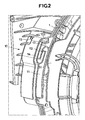
- figure 2 shows a partially exploded perspective view of the tub, around the system,
- figure 3 shows a side perspective view of the tub before its left flange is mounted.
- The figures represent an integrated overflow system for a top-loading washing machine according to the invention, whose tub includes, around its junction plane with the corresponding flange 3, a system forming a
labyrinth 10 open on the side of the junction plane with the flange 3, including an ascendinghollow baffle 11 that starts inside the tub at a predetermined spot and opens into a meander forming asiphon 12, which opens into aroom 13 with an L-shaped deflector 131 by communicating on the one hand with a descendingbaffle 14 next to theascending baffle 11 and coming into the open air around the base of this last baffle and, on the other hand, with anozzle 15 connected directly to theroom 13 and coming out behind the L-shaped deflector 131. - In examining the figures in more detail, one notices first of all, by simultaneously and comparatively examining figures 1 and 2, that the
labyrinth 10 for the flow of excess water is made as a hollow in the junction plane of thetub body 1 with the corresponding flange 3, which includes thelabyrinth 10lid 31 that in this way, during assembly of the left flange 3 with themachine tub body 1, definitively materialises thebaffles labyrinth 10 thereby constituting the overflow according to the invention. Thetub body 1 is assembled with its flanges 3 according to the conventional technique, without any other constraint than to align the system with itslid 31, as shown in figure 2. - One also notes on the same figures that the
siphon 12, provided it is filled with water, resists the passage of foam and vapour. Regarding condensation water than can appear in the upper part of the system, it flows normally inside the drum through theascending baffle 11 of thelabyrinth 10 by overflowing thesiphon 12 as soon as the siphon is full. - In referring to figure 2, one notes that the
nozzle 15 coming out inside and behind the L-shaped deflector 131 can, given the shape of the saiddeflector 131, prime thesiphon 12 without any risk of projection at the entry to the descendingbaffle 14. However generally, thesiphon 12 fills up with condensed vapour produced during the wash cycle. - If one now refers to figure 3, showing a side perspective view of the tub before its left flange 3 is mounted, one sees that the overfill does not cause any oversizing of the machine, given its position.
- The overflow according to the invention has been designed for top-loading rotating-drum washing machines, but there is no reason it cannot be used on front-loading machines, subject to minor adaptations according to current techniques.
Claims (4)
- Integrated overflow system for a top-loading rotating-drum washing machine, characterised in that it is constituted of a labyrinth (10) incorporated in the machine tub body (1).
- Integrated overflow system according to claim 1, characterised in that this labyrinth (10) is made as a hollow in one side of the machine tub body (1), in the junction plane, with one of its lateral flanges (3), which overlaps it when it is mounted on the said body (1).
- Integrated overflow system according to claim 1 or 2, characterised in that the labyrinth (10) is comprised of an ascending baffle (11) that begins inside the tub body and communicates with it, opening into a meander that forms a siphon (12), which opens into a room (13) that includes an L-shaped deflector (131) in its upper part, which communicates, on the one hand, with a descending baffle (14) next to the ascending baffle (11) opening into the open air and, on the other hand, with a nozzle (15) connected directly to the room (13) and coming out behind the room L-shaped deflector (131).
- Integrated overflow system according to claim 2, characterised in that the overlap of the labyrinth (10), made in the tub junction plane by one of the corresponding lateral flanges (3), is obtained via a plate forming a lid (31) of corresponding dimensions, arranged radially to the periphery of the junction plane of the said corresponding flange (3).
Priority Applications (7)
| Application Number | Priority Date | Filing Date | Title |
|---|---|---|---|
| ES06008714T ES2333148T3 (en) | 2006-04-27 | 2006-04-27 | INTEGRATED CUBA FLOODING SYSTEM FOR UPPER LOADING WASHING MACHINE. |
| DE602006010177T DE602006010177D1 (en) | 2006-04-27 | 2006-04-27 | Integrated tub overflow device for a obenbeschickbare washing machine |
| EP06008714A EP1849906B1 (en) | 2006-04-27 | 2006-04-27 | Integrated tub overflow system for top-loading washing machine |
| PL06008714T PL1849906T3 (en) | 2006-04-27 | 2006-04-27 | Integrated tub overflow system for top-loading washing machine |
| AT06008714T ATE447638T1 (en) | 2006-04-27 | 2006-04-27 | INTEGRATED SUDDING CONTAINER OVERFLOW DEVICE FOR A TOP-LOADING WASHING MACHINE |
| RU2008146774/12A RU2425916C2 (en) | 2006-04-27 | 2007-03-01 | Inbuilt system of tank overflow in washing machine tank with top loading |
| PCT/EP2007/001778 WO2007124806A1 (en) | 2006-04-27 | 2007-03-01 | Integrated tub overflow system for top-loading washing machine |
Applications Claiming Priority (1)
| Application Number | Priority Date | Filing Date | Title |
|---|---|---|---|
| EP06008714A EP1849906B1 (en) | 2006-04-27 | 2006-04-27 | Integrated tub overflow system for top-loading washing machine |
Publications (2)
| Publication Number | Publication Date |
|---|---|
| EP1849906A1 true EP1849906A1 (en) | 2007-10-31 |
| EP1849906B1 EP1849906B1 (en) | 2009-11-04 |
Family
ID=37075058
Family Applications (1)
| Application Number | Title | Priority Date | Filing Date |
|---|---|---|---|
| EP06008714A Expired - Lifetime EP1849906B1 (en) | 2006-04-27 | 2006-04-27 | Integrated tub overflow system for top-loading washing machine |
Country Status (7)
| Country | Link |
|---|---|
| EP (1) | EP1849906B1 (en) |
| AT (1) | ATE447638T1 (en) |
| DE (1) | DE602006010177D1 (en) |
| ES (1) | ES2333148T3 (en) |
| PL (1) | PL1849906T3 (en) |
| RU (1) | RU2425916C2 (en) |
| WO (1) | WO2007124806A1 (en) |
Cited By (5)
| Publication number | Priority date | Publication date | Assignee | Title |
|---|---|---|---|---|
| ITMC20090027A1 (en) * | 2009-02-13 | 2010-08-14 | Meccanica Generale Srl | BATHTUB FOR WASHING MACHINE OR DISHWASHER MAKER CONDUCTED. |
| EP2273003A1 (en) * | 2009-07-09 | 2011-01-12 | Miele & Cie. KG | Washing machine with a lye container in a housing |
| CN109281132A (en) * | 2018-09-27 | 2019-01-29 | 无锡小天鹅股份有限公司 | Anti-overflow foam device and wall-mounted device for clothing processing with it |
| CN109518428A (en) * | 2017-09-20 | 2019-03-26 | 青岛海尔洗衣机有限公司 | A kind of washing machine water overflowing structure and washing machine |
| CN110541285A (en) * | 2018-05-29 | 2019-12-06 | 日立环球生活方案株式会社 | Washing machine |
Citations (5)
| Publication number | Priority date | Publication date | Assignee | Title |
|---|---|---|---|---|
| DE1157578B (en) * | 1958-07-26 | 1963-11-21 | Constructa Werke G M B H | Washing machine with an automatically controlled adjustment device for the level of the liquor depending on the amount of laundry |
| EP0110482A1 (en) * | 1982-12-06 | 1984-06-13 | Constructions Electro-Mecaniques D'amiens | Linen laundering machine with a drain conduit opening at the bottom of the tub |
| EP0335452A1 (en) | 1988-03-29 | 1989-10-04 | Whirlpool France | Washing machine with an overflow |
| EP0421442A2 (en) | 1989-10-05 | 1991-04-10 | Sanyo Electric Co., Ltd. | drum-type washing machine |
| DE19936420A1 (en) * | 1999-08-03 | 2001-02-08 | Bsh Bosch Siemens Hausgeraete | Domestic machine has collection trough with trigger element for blocking valve, overflow device mounted on or in soapy water feed line from inflow basin to soapy water container |
Family Cites Families (2)
| Publication number | Priority date | Publication date | Assignee | Title |
|---|---|---|---|---|
| FR2533026A1 (en) * | 1982-09-14 | 1984-03-16 | Esswein Sa | CONTROLLED LEVEL LIQUID SUPPLY DEVICE AND APPLICATION TO WASHING MACHINE |
| JP4293093B2 (en) * | 2004-09-06 | 2009-07-08 | パナソニック株式会社 | Washing machine |
-
2006
- 2006-04-27 PL PL06008714T patent/PL1849906T3/en unknown
- 2006-04-27 DE DE602006010177T patent/DE602006010177D1/en not_active Expired - Lifetime
- 2006-04-27 ES ES06008714T patent/ES2333148T3/en not_active Expired - Lifetime
- 2006-04-27 AT AT06008714T patent/ATE447638T1/en not_active IP Right Cessation
- 2006-04-27 EP EP06008714A patent/EP1849906B1/en not_active Expired - Lifetime
-
2007
- 2007-03-01 RU RU2008146774/12A patent/RU2425916C2/en not_active IP Right Cessation
- 2007-03-01 WO PCT/EP2007/001778 patent/WO2007124806A1/en not_active Ceased
Patent Citations (5)
| Publication number | Priority date | Publication date | Assignee | Title |
|---|---|---|---|---|
| DE1157578B (en) * | 1958-07-26 | 1963-11-21 | Constructa Werke G M B H | Washing machine with an automatically controlled adjustment device for the level of the liquor depending on the amount of laundry |
| EP0110482A1 (en) * | 1982-12-06 | 1984-06-13 | Constructions Electro-Mecaniques D'amiens | Linen laundering machine with a drain conduit opening at the bottom of the tub |
| EP0335452A1 (en) | 1988-03-29 | 1989-10-04 | Whirlpool France | Washing machine with an overflow |
| EP0421442A2 (en) | 1989-10-05 | 1991-04-10 | Sanyo Electric Co., Ltd. | drum-type washing machine |
| DE19936420A1 (en) * | 1999-08-03 | 2001-02-08 | Bsh Bosch Siemens Hausgeraete | Domestic machine has collection trough with trigger element for blocking valve, overflow device mounted on or in soapy water feed line from inflow basin to soapy water container |
Cited By (7)
| Publication number | Priority date | Publication date | Assignee | Title |
|---|---|---|---|---|
| ITMC20090027A1 (en) * | 2009-02-13 | 2010-08-14 | Meccanica Generale Srl | BATHTUB FOR WASHING MACHINE OR DISHWASHER MAKER CONDUCTED. |
| EP2218816A1 (en) * | 2009-02-13 | 2010-08-18 | Meccanica Generale S.R.L. | Tub for washer or washer/dryer machine provided with conduits |
| EP2273003A1 (en) * | 2009-07-09 | 2011-01-12 | Miele & Cie. KG | Washing machine with a lye container in a housing |
| CN109518428A (en) * | 2017-09-20 | 2019-03-26 | 青岛海尔洗衣机有限公司 | A kind of washing machine water overflowing structure and washing machine |
| CN110541285A (en) * | 2018-05-29 | 2019-12-06 | 日立环球生活方案株式会社 | Washing machine |
| CN110541285B (en) * | 2018-05-29 | 2021-08-03 | 日立环球生活方案株式会社 | washing machine |
| CN109281132A (en) * | 2018-09-27 | 2019-01-29 | 无锡小天鹅股份有限公司 | Anti-overflow foam device and wall-mounted device for clothing processing with it |
Also Published As
| Publication number | Publication date |
|---|---|
| RU2008146774A (en) | 2010-06-10 |
| ATE447638T1 (en) | 2009-11-15 |
| DE602006010177D1 (en) | 2009-12-17 |
| PL1849906T3 (en) | 2010-04-30 |
| ES2333148T3 (en) | 2010-02-17 |
| WO2007124806A1 (en) | 2007-11-08 |
| RU2425916C2 (en) | 2011-08-10 |
| EP1849906B1 (en) | 2009-11-04 |
Similar Documents
| Publication | Publication Date | Title |
|---|---|---|
| CN103668857B (en) | Wall-mounted drum washing machine and method for detecting installation abnormality and fall of wall-mounted drum washing machine | |
| US10472758B2 (en) | Wall-mounted drum-type washing machine | |
| US10260190B2 (en) | Wall-mounted drum type washing machine | |
| US10487434B2 (en) | Wall-mounted drum type washing machine | |
| US9783924B2 (en) | Wall-mounted drum-type washing machine | |
| US10174451B2 (en) | Wall-mounted drum-type washing machine | |
| US10428452B2 (en) | Wall-mounted drum type washing machine | |
| US10301758B2 (en) | Wall-mounted drum-type washing machine | |
| WO2007124806A1 (en) | Integrated tub overflow system for top-loading washing machine | |
| US20180044837A1 (en) | Washing machine | |
| US5868011A (en) | Water traps for washing machines | |
| CN103958761A (en) | Wall-mounted drum type washing machine | |
| US12024810B2 (en) | Washing machine | |
| US8961704B2 (en) | Dishwasher | |
| AU2005203224A1 (en) | Washing machine, apparatus and method of controlling the same | |
| KR20130064627A (en) | Wall mounted mini drum type washing machine | |
| KR20100083208A (en) | Tub and washing machine having the same | |
| KR20200095920A (en) | sensor module and clothes treatment apparatus having the same | |
| US20050257574A1 (en) | Washing machine with improved decoration panel mounting structure and method of mounting decoration panel on washing maching | |
| KR102160979B1 (en) | Washing Machine | |
| CN106659356A (en) | Dishwasher and method of manufacturing the same | |
| KR20130064626A (en) | Wall mounted mini drum type washing machine | |
| KR20130064622A (en) | Wall mounted mini drum type washing machine | |
| KR20130064623A (en) | Wall mounted mini drum type washing machine |
Legal Events
| Date | Code | Title | Description |
|---|---|---|---|
| PUAI | Public reference made under article 153(3) epc to a published international application that has entered the european phase |
Free format text: ORIGINAL CODE: 0009012 |
|
| 17P | Request for examination filed |
Effective date: 20070911 |
|
| AK | Designated contracting states |
Kind code of ref document: A1 Designated state(s): AT BE BG CH CY CZ DE DK EE ES FI FR GB GR HU IE IS IT LI LT LU LV MC NL PL PT RO SE SI SK TR |
|
| AX | Request for extension of the european patent |
Extension state: AL BA HR MK YU |
|
| AKX | Designation fees paid |
Designated state(s): AT BE BG CH CY CZ DE DK EE ES FI FR GB GR HU IE IS IT LI LT LU LV MC NL PL PT RO SE SI SK TR |
|
| 17Q | First examination report despatched |
Effective date: 20090325 |
|
| GRAP | Despatch of communication of intention to grant a patent |
Free format text: ORIGINAL CODE: EPIDOSNIGR1 |
|
| GRAS | Grant fee paid |
Free format text: ORIGINAL CODE: EPIDOSNIGR3 |
|
| GRAA | (expected) grant |
Free format text: ORIGINAL CODE: 0009210 |
|
| AK | Designated contracting states |
Kind code of ref document: B1 Designated state(s): AT BE BG CH CY CZ DE DK EE ES FI FR GB GR HU IE IS IT LI LT LU LV MC NL PL PT RO SE SI SK TR |
|
| REG | Reference to a national code |
Ref country code: GB Ref legal event code: FG4D |
|
| REG | Reference to a national code |
Ref country code: CH Ref legal event code: EP |
|
| REG | Reference to a national code |
Ref country code: IE Ref legal event code: FG4D |
|
| REF | Corresponds to: |
Ref document number: 602006010177 Country of ref document: DE Date of ref document: 20091217 Kind code of ref document: P |
|
| REG | Reference to a national code |
Ref country code: ES Ref legal event code: FG2A Ref document number: 2333148 Country of ref document: ES Kind code of ref document: T3 |
|
| NLV1 | Nl: lapsed or annulled due to failure to fulfill the requirements of art. 29p and 29m of the patents act | ||
| LTIE | Lt: invalidation of european patent or patent extension |
Effective date: 20091104 |
|
| PG25 | Lapsed in a contracting state [announced via postgrant information from national office to epo] |
Ref country code: IS Free format text: LAPSE BECAUSE OF FAILURE TO SUBMIT A TRANSLATION OF THE DESCRIPTION OR TO PAY THE FEE WITHIN THE PRESCRIBED TIME-LIMIT Effective date: 20100304 Ref country code: SE Free format text: LAPSE BECAUSE OF FAILURE TO SUBMIT A TRANSLATION OF THE DESCRIPTION OR TO PAY THE FEE WITHIN THE PRESCRIBED TIME-LIMIT Effective date: 20091104 Ref country code: PT Free format text: LAPSE BECAUSE OF FAILURE TO SUBMIT A TRANSLATION OF THE DESCRIPTION OR TO PAY THE FEE WITHIN THE PRESCRIBED TIME-LIMIT Effective date: 20100304 Ref country code: LT Free format text: LAPSE BECAUSE OF FAILURE TO SUBMIT A TRANSLATION OF THE DESCRIPTION OR TO PAY THE FEE WITHIN THE PRESCRIBED TIME-LIMIT Effective date: 20091104 Ref country code: FI Free format text: LAPSE BECAUSE OF FAILURE TO SUBMIT A TRANSLATION OF THE DESCRIPTION OR TO PAY THE FEE WITHIN THE PRESCRIBED TIME-LIMIT Effective date: 20091104 |
|
| REG | Reference to a national code |
Ref country code: PL Ref legal event code: T3 |
|
| PG25 | Lapsed in a contracting state [announced via postgrant information from national office to epo] |
Ref country code: CY Free format text: LAPSE BECAUSE OF FAILURE TO SUBMIT A TRANSLATION OF THE DESCRIPTION OR TO PAY THE FEE WITHIN THE PRESCRIBED TIME-LIMIT Effective date: 20091104 Ref country code: SI Free format text: LAPSE BECAUSE OF FAILURE TO SUBMIT A TRANSLATION OF THE DESCRIPTION OR TO PAY THE FEE WITHIN THE PRESCRIBED TIME-LIMIT Effective date: 20091104 Ref country code: LV Free format text: LAPSE BECAUSE OF FAILURE TO SUBMIT A TRANSLATION OF THE DESCRIPTION OR TO PAY THE FEE WITHIN THE PRESCRIBED TIME-LIMIT Effective date: 20091104 |
|
| PG25 | Lapsed in a contracting state [announced via postgrant information from national office to epo] |
Ref country code: BE Free format text: LAPSE BECAUSE OF FAILURE TO SUBMIT A TRANSLATION OF THE DESCRIPTION OR TO PAY THE FEE WITHIN THE PRESCRIBED TIME-LIMIT Effective date: 20091104 Ref country code: AT Free format text: LAPSE BECAUSE OF FAILURE TO SUBMIT A TRANSLATION OF THE DESCRIPTION OR TO PAY THE FEE WITHIN THE PRESCRIBED TIME-LIMIT Effective date: 20091104 |
|
| PG25 | Lapsed in a contracting state [announced via postgrant information from national office to epo] |
Ref country code: DK Free format text: LAPSE BECAUSE OF FAILURE TO SUBMIT A TRANSLATION OF THE DESCRIPTION OR TO PAY THE FEE WITHIN THE PRESCRIBED TIME-LIMIT Effective date: 20091104 Ref country code: BG Free format text: LAPSE BECAUSE OF FAILURE TO SUBMIT A TRANSLATION OF THE DESCRIPTION OR TO PAY THE FEE WITHIN THE PRESCRIBED TIME-LIMIT Effective date: 20100204 Ref country code: EE Free format text: LAPSE BECAUSE OF FAILURE TO SUBMIT A TRANSLATION OF THE DESCRIPTION OR TO PAY THE FEE WITHIN THE PRESCRIBED TIME-LIMIT Effective date: 20091104 Ref country code: RO Free format text: LAPSE BECAUSE OF FAILURE TO SUBMIT A TRANSLATION OF THE DESCRIPTION OR TO PAY THE FEE WITHIN THE PRESCRIBED TIME-LIMIT Effective date: 20091104 |
|
| PG25 | Lapsed in a contracting state [announced via postgrant information from national office to epo] |
Ref country code: CZ Free format text: LAPSE BECAUSE OF FAILURE TO SUBMIT A TRANSLATION OF THE DESCRIPTION OR TO PAY THE FEE WITHIN THE PRESCRIBED TIME-LIMIT Effective date: 20091104 Ref country code: SK Free format text: LAPSE BECAUSE OF FAILURE TO SUBMIT A TRANSLATION OF THE DESCRIPTION OR TO PAY THE FEE WITHIN THE PRESCRIBED TIME-LIMIT Effective date: 20091104 |
|
| PLBE | No opposition filed within time limit |
Free format text: ORIGINAL CODE: 0009261 |
|
| STAA | Information on the status of an ep patent application or granted ep patent |
Free format text: STATUS: NO OPPOSITION FILED WITHIN TIME LIMIT |
|
| 26N | No opposition filed |
Effective date: 20100805 |
|
| PG25 | Lapsed in a contracting state [announced via postgrant information from national office to epo] |
Ref country code: GR Free format text: LAPSE BECAUSE OF FAILURE TO SUBMIT A TRANSLATION OF THE DESCRIPTION OR TO PAY THE FEE WITHIN THE PRESCRIBED TIME-LIMIT Effective date: 20100205 |
|
| PG25 | Lapsed in a contracting state [announced via postgrant information from national office to epo] |
Ref country code: MC Free format text: LAPSE BECAUSE OF NON-PAYMENT OF DUE FEES Effective date: 20100430 |
|
| REG | Reference to a national code |
Ref country code: CH Ref legal event code: PL |
|
| PG25 | Lapsed in a contracting state [announced via postgrant information from national office to epo] |
Ref country code: IE Free format text: LAPSE BECAUSE OF NON-PAYMENT OF DUE FEES Effective date: 20100427 |
|
| PG25 | Lapsed in a contracting state [announced via postgrant information from national office to epo] |
Ref country code: CH Free format text: LAPSE BECAUSE OF NON-PAYMENT OF DUE FEES Effective date: 20100430 Ref country code: LI Free format text: LAPSE BECAUSE OF NON-PAYMENT OF DUE FEES Effective date: 20100430 |
|
| PG25 | Lapsed in a contracting state [announced via postgrant information from national office to epo] |
Ref country code: HU Free format text: LAPSE BECAUSE OF FAILURE TO SUBMIT A TRANSLATION OF THE DESCRIPTION OR TO PAY THE FEE WITHIN THE PRESCRIBED TIME-LIMIT Effective date: 20100505 Ref country code: NL Free format text: LAPSE BECAUSE OF FAILURE TO SUBMIT A TRANSLATION OF THE DESCRIPTION OR TO PAY THE FEE WITHIN THE PRESCRIBED TIME-LIMIT Effective date: 20091104 Ref country code: LU Free format text: LAPSE BECAUSE OF NON-PAYMENT OF DUE FEES Effective date: 20100427 |
|
| PG25 | Lapsed in a contracting state [announced via postgrant information from national office to epo] |
Ref country code: TR Free format text: LAPSE BECAUSE OF FAILURE TO SUBMIT A TRANSLATION OF THE DESCRIPTION OR TO PAY THE FEE WITHIN THE PRESCRIBED TIME-LIMIT Effective date: 20091104 |
|
| PGFP | Annual fee paid to national office [announced via postgrant information from national office to epo] |
Ref country code: ES Payment date: 20120425 Year of fee payment: 7 |
|
| PGFP | Annual fee paid to national office [announced via postgrant information from national office to epo] |
Ref country code: PL Payment date: 20130322 Year of fee payment: 8 |
|
| REG | Reference to a national code |
Ref country code: ES Ref legal event code: FD2A Effective date: 20150730 |
|
| REG | Reference to a national code |
Ref country code: PL Ref legal event code: LAPE |
|
| PG25 | Lapsed in a contracting state [announced via postgrant information from national office to epo] |
Ref country code: PL Free format text: LAPSE BECAUSE OF NON-PAYMENT OF DUE FEES Effective date: 20140427 |
|
| PG25 | Lapsed in a contracting state [announced via postgrant information from national office to epo] |
Ref country code: ES Free format text: LAPSE BECAUSE OF NON-PAYMENT OF DUE FEES Effective date: 20140428 |
|
| REG | Reference to a national code |
Ref country code: FR Ref legal event code: PLFP Year of fee payment: 11 |
|
| PGFP | Annual fee paid to national office [announced via postgrant information from national office to epo] |
Ref country code: DE Payment date: 20160421 Year of fee payment: 11 Ref country code: GB Payment date: 20160421 Year of fee payment: 11 |
|
| PGFP | Annual fee paid to national office [announced via postgrant information from national office to epo] |
Ref country code: IT Payment date: 20160427 Year of fee payment: 11 Ref country code: FR Payment date: 20160421 Year of fee payment: 11 |
|
| REG | Reference to a national code |
Ref country code: DE Ref legal event code: R119 Ref document number: 602006010177 Country of ref document: DE |
|
| GBPC | Gb: european patent ceased through non-payment of renewal fee |
Effective date: 20170427 |
|
| REG | Reference to a national code |
Ref country code: FR Ref legal event code: ST Effective date: 20171229 |
|
| PG25 | Lapsed in a contracting state [announced via postgrant information from national office to epo] |
Ref country code: FR Free format text: LAPSE BECAUSE OF NON-PAYMENT OF DUE FEES Effective date: 20170502 Ref country code: DE Free format text: LAPSE BECAUSE OF NON-PAYMENT OF DUE FEES Effective date: 20171103 |
|
| PG25 | Lapsed in a contracting state [announced via postgrant information from national office to epo] |
Ref country code: GB Free format text: LAPSE BECAUSE OF NON-PAYMENT OF DUE FEES Effective date: 20170427 |
|
| PG25 | Lapsed in a contracting state [announced via postgrant information from national office to epo] |
Ref country code: IT Free format text: LAPSE BECAUSE OF NON-PAYMENT OF DUE FEES Effective date: 20170427 |