EP1848975B1 - A method and a system for adaptive compensation of the temperature drift of a sensor - Google Patents
A method and a system for adaptive compensation of the temperature drift of a sensor Download PDFInfo
- Publication number
- EP1848975B1 EP1848975B1 EP05821877A EP05821877A EP1848975B1 EP 1848975 B1 EP1848975 B1 EP 1848975B1 EP 05821877 A EP05821877 A EP 05821877A EP 05821877 A EP05821877 A EP 05821877A EP 1848975 B1 EP1848975 B1 EP 1848975B1
- Authority
- EP
- European Patent Office
- Prior art keywords
- sensor
- temperature
- signal
- torque
- unloaded
- Prior art date
- Legal status (The legal status is an assumption and is not a legal conclusion. Google has not performed a legal analysis and makes no representation as to the accuracy of the status listed.)
- Expired - Lifetime
Links
Images







Classifications
-
- G—PHYSICS
- G01—MEASURING; TESTING
- G01L—MEASURING FORCE, STRESS, TORQUE, WORK, MECHANICAL POWER, MECHANICAL EFFICIENCY, OR FLUID PRESSURE
- G01L25/00—Testing or calibrating of apparatus for measuring force, torque, work, mechanical power, or mechanical efficiency
- G01L25/003—Testing or calibrating of apparatus for measuring force, torque, work, mechanical power, or mechanical efficiency for measuring torque
Definitions
- the document EP1283414 presents a method and a device for compensation of the temperature drift of a sensor. Preliminary, the temperature characteristic of the torque offset is measured when the shaft is unloaded. Combined with the measurement of the temperature during operation, the torque measurement can be compensated.
- a trigger signal for a disengaged drive train can be achieved by analyzing characteristics of the sensor signal such as the sudden change in derivative of the sensor signal or the amplitude of the torque ripple information that both changes when the torque sensor is structurally disengaged from the drive train, due to play in the transmission.
Landscapes
- Physics & Mathematics (AREA)
- General Physics & Mathematics (AREA)
- Control Of Transmission Device (AREA)
- Indication And Recording Devices For Special Purposes And Tariff Metering Devices (AREA)
- Force Measurement Appropriate To Specific Purposes (AREA)
- Feedback Control In General (AREA)
Abstract
Description
- The present invention relates to a method and a system for adaptive compensation of the temperature drift of a sensor in a mechanical equipment, and preferably for a torque sensor designed for a shaft driven by a motor/engine in a process, a production line or a vehicle.
- More specifically the invention concerns a compensation system for minimizing offset variations in a torque sensor in an automotive power train.
- Due to increasing levels of traffic pollution caused by vehicle exhaust emissions, new government legislations for lower exhaust emission limits, customer demands for lower fuel consumption and increased smoothness of the transmission there is a pressing need to improve the efficiency of engines and transmissions. Also in the field of motor sport the competition is very high and it is of utmost importance to apply the best technology for the race car engines and their drive trains.
- Electronic control systems for combustion engines include a number of sensors and systems for determining various engine operating conditions. Many of these sensors are working in harsh environments and are subjected to widely varying operating conditions and the requirements on a sensor are very demanding in terms of durability, long term stability and the ability to operate over a large temperature range. Typical temperature ranges that are encountered in automotive applications range from -40 ºC up to +150 ºC. In this temperature range it is required that the sensor produces a reliable output signal throughout its entire life.
- One solution to the problem of temperature stability is to design a sensor that is sufficiently stable throughout the temperature range and throughout the lifetime of the sensor. The problem with such a sensor is that it is either too costly to produce for automotive purposes or too bulky to integrate in the power train.
- Another solution is to add a temperature calibration step in the production where the temperature characteristics of the sensor are compensated by adjustments of the sensor or in the electronics. Since this operation has to be performed on each individual sensor in production this adds extra cost to the component.
- A further complication is that a torque sensor for automotive applications is usually for practical reasons designed by two separate parts, where one part is the load carrying shaft and the other part is a surrounding yoke, which parts are combined first when the sensor is mounted on the gear box. A temperature calibration step of the offset drift of the sensor has to be performed on the complete sensor and can not be done on the separate parts. A further problem with the temperature calibration solution is that it does not account for long term effects on temperature characteristics.
- A straightforward way to calibrate the sensor offset in the application is to perform a zero reset of the sensor during gearshifts, when the drive train is unloaded. A limitation of that approach is that the zero reset is only valid at that particular temperature level. When the temperature changes a new zero reset/calibration has to be performed in order to achieve reliable sensor data.
-
US 6,658,345 describes how the temperature characteristics of a sensor can be compensated after installation in an application. A problem with this approach is that it requires the input of a separate temperature sensor. It further relies on a key switch for start and stop and can only update the sensor model at start or stop of the engine. - the document
US5412998 discloses a method and a device for compensation of the temperature drift of a sensor, designed to measure the torque of a shaft comprising the steps of recurrently measuring the sensor signal and determining an associated temperature, compensating the measured signal value using stored offset values calculated during a correction mode when the shaft is unloaded. - The document
EP1283414 presents a method and a device for compensation of the temperature drift of a sensor. Preliminary, the temperature characteristic of the torque offset is measured when the shaft is unloaded. Combined with the measurement of the temperature during operation, the torque measurement can be compensated. - The object of the present invention is to solve the problems indicated above and to provide a method and a system that effectively compensate the temperature dependence of the sensor signal value using a calculated offset value and thereby improving the value of the sensor signal.
- A further important object of the present invention is to provide such automotive components at a low cost.
- These and other objects are achieved according to the present invention by a method as described in and characterised by
claim 1 and a system as described in and characterised byclaim 12, and a computer program product as described in and characterised byclaim 13. - The invention uses naturally occurring operation points of the application in which the loading state of the shaft or drive train and the sensor are known. Sensor data from these operation points are stored in a memory/database and are used to update a model of the sensor characteristics. Such operation points that are readily available occur during gearshift when a drive train is disengaged and the sensor is known to be unloaded or at least close to unloaded.
- Sensor data and temperature data are collected, after suitable filtering, when the shaft or drive train is unloaded and is used
- as information about the sensor offset at that particular temperature. When data from at least two temperature levels is collected this information is used to determine parameters in a sensor model that describe the temperature dependence of the sensor offset. The sensor model is used to continuously calculate the sensor offset based on the temperature signal.
- A temperature signal is preferably obtained from the sensor excitation/supply unit by measuring changes in the electrical properties of the sensor, but can also be obtained from an external temperature sensor or by other means from the supervising system. Information about when the drive train or the sensor is unloaded can be obtained in several different ways. In the case of an automatic transmission or an automated manual transmission a signal can be obtained from the supervising system when the drive train is disengaged. For a manual transmission a signal can be obtained from a switch position of the clutch pedal and/or the shift lever. This signal can also be obtained by monitoring specific characteristics of the torque signal.
- In a further embodiment of the invention a trigger signal for a disengaged drive train can be achieved by analyzing characteristics of the sensor signal such as the sudden change in derivative of the sensor signal or the amplitude of the torque ripple information that both changes when the torque sensor is structurally disengaged from the drive train, due to play in the transmission.
- The most important feature of the invention is to use operation points, at least two, when the drive train is unloaded/disengaged in order determine/update a model of the temperature dependence of the sensor offset.
- Another important feature of the invention is to use the electrical properties of the sensor as a measure of the operating temperature which eliminates the need of an external temperature sensor.
- A further important feature of the invention is to analyze the characteristics of the sensor signal in order to obtain a trigger signal for a disengaged drive train.
- The primary advantage of the invention is that the temperature characteristic of the sensor is greatly enhanced without the need for a costly or difficult temperature calibration step in the manufacturing process. The adaptation scheme is performed during operation in the application. Furthermore the temperature performance of the sensor is guaranteed to be maintained throughout the lifetime of the sensor.
- Other objects, features, and advantages of the invention will become evident in light of the following detailed description considered in conjunction with the enclosed drawings and defined by any of the dependent claims.
- For better understanding of the present invention, reference will be made to the accompanying drawing.
-
Figure 1 is a schematic block diagram and gives an overview of the preferred embodiment of the invention. -
Figure 2 illustrates a signal processing and block diagram according to the invention. -
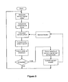
Figure 3 is a flow chart of the invention. -
Figure 4 illustrates a gearshift with an offset of the sensor signal. -
Figure 5 illustrates a gearshift with a corrected offset of the sensor signal. -
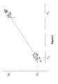
Figure 6 illustrates measurements of sensor output at zero load at high and low temperatures. -
Figure 7 illustrates measurements of sensor output at zero load at a continuous temperature range. -
Figure 8 illustrates measurements of sensor output at zero load at a continuous temperature range with a linear and a higher order sensor model. -
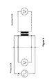
Figure 9 illustrates a four-wire measurement of the impedance of the primary circuit of the sensor. -
Figure 10 illustrates the variation in torque ripple with engine engaged and disengaged. -
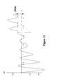
Figure 11 illustrates the torque variation around zero indicating play in the transmission. - The preferred embodiment of the invention consists, as illustrated in
figure 1 , of atorque sensor 1 that is located in thedrive train 2 of a vehicle. Thetorque sensor 1 is electrically connected to anelectronic unit 3 consisting of anexcitation unit 4, an A/D-converter 5, a calculation orprocessing unit 6 and amemory 7. - The
electronic unit 3 is connected to a gearbox control unit, not shown, that controls/operates a mechanical clutch 17 in thedrive train 2. When themechanical clutch 17 is disengaged the state of thedrive train 2 is known to be unloaded. This can also be achieved by other means which will be discussed later. - As can be seen in
figure 2 thesensor 1 is supplied with anexcitation signal 4a from theexcitation unit 4 and thesensor 1 produces anoutput signal 1a that is sampled by the A/D-converter 5. The digital signal 5a from the A/D-converter 5 is processed by thecalculation unit 6 in order to obtain a linear and temperature stable output indicative of the torsional load of thetorque sensor 1. Thecalculation unit 6 further comprise atemperature calculation unit 8, aparameter calculation unit 9, ademodulation unit 10, an offsetcompensation unit 11, alinearisation unit 12 and anoutput compensation unit 13. - The
demodulation unit 10 infigure 2 consists of filtering and decimation of the signal 5a synchronised with theexcitation signal 4a. It may also consist of further filtering and processing in order to improve noise and stability of thedemodulated signal 10a. - In the preferred embodiment a temperature signal is determined based on characteristics of the primary circuit of
sensor 1. The temperature signal is used by thecalculation unit 6 to compensate the temperature drift of thesensor 1 based on a mathematical model, e.g. stored in thememory 7. - When it is known from a supervising
system 14, e.g. a gearbox control unit that thedrive train 2 is unloaded sensor signal data/values and temperature signal data/values are collected and stored in thememory 7. Data from zero load conditions gathered at several, at least two, different temperature levels form a database that is used to recurrently update the sensor model. Zero load state is indicated infigure 1 as atrigger signal 14a from the supervisingsystem 14. - The output signal of the
calculation unit 6 can be transferred to and used by the gearbox control unit (not shown) in order to optimise the gearshifts, detect wear of transmission components and so on, but it can also be used by an engine management system in order to diagnose, control and optimize theengine 16. - Based on the data monitored and collected for a number of different
temperature levels parameters linearisation unit 12 and anoutput compensation unit 13 and includes a possible compensation of the sensitivity/gain drift of thesensor 1, further filtering and/or adaption of output levels of the resultingoutput signal 13a. One specific operation point of the application that is used by the invention is during gearshift when thedrive train 2 is unloaded. - A flowchart that describes the method according to the invention is shown in
figure 3 and consists of one part that runs continuously, left side, and compensates the temperature offset of the sensor signal. The other part of the flow is run when the drive train is known to be unloaded, right side. - The first part of the flow consists of the steps of measuring a signal value from the sensor which means that the secondary signal of the sensor is converted into a digital signal indicative of the torsional load. This step may consist of the steps of an A/D-conversion and also a demodulation of the signal that can be either in the digital or the analogue domain. A second step of the flow consists of determining a temperature value, which in the preferred embodiment is achieved by measuring the change in impedance of the primary circuit of the sensor. By knowing the relation between impedance and temperature a temperature value can thus be determined. In a third step the temperature value is used to calculate the temperature offset of the sensor at this particular temperature. This is done based on a relation between temperature and sensor offset that is stored in a database in the electronic unit. In a fourth step the calculated value of the sensor offset is used to compensate the output signal of the sensor thereby obtaining a temperature compensated output signal. In the fifth and final step of the continuous part of the flow the state of the drive train is detected.
- If the drive train is found to be unloaded the present values of the sensor signal and the temperature signal are stored in a memory/database. In order to improve the quality of the stored values this step may consist of an optional filtering of the temperature and sensor signals. In the next step the new values in the database, together with values measured previously, are used to determine the relation between temperature values and sensor offset values. This relation is the one that is used to calculate a sensor offset in the continuous part of the flowchart. This relation can, for instance, be established by determining parameters in a general expression between sensor offset and temperature value using known methods such as "least squares".
- Both the sensor signals and temperature signals are preferably filtered using common methods in order to reduce noise levels, torque ripple, torque oscillations or other disturbances on the signals. If a known resonance exists in the system a filter can be designed that reduces or cancels that resonance.
- The data pairs are stored in a memory and forms a database that represents the variation of the sensor offset at different temperatures. Every new gearshift, or other occasion when data is collected, results in a new data pair in the database. Before the new data pairs are stored in the data base a control of the stability of the torque signal may be included. If a certain stability criterion is not met the data pair is rejected.
-
Figure 4 illustrates a typical gearshift of asynchronized gearbox 15 where there is an offset on the sensor signal. The first part a shows the torque level before the gearshift is initiated. In the second part b of the curve the torque level is reduced while the clutch 17 disengages. When thedrive train 2 is fully disengaged the drop in torque flattens out for a short period c before the gearshift, is operated. At this point the drive train and consequently the torque sensor are unloaded (at zero torque level) and a measurement of the sensor signal and temperature signal can be made and stored in the database. Since the sensor signal in this example has an offset the sensor value at part c of the curve is not equal to zero. The next part of the curve shows how the operation of the gear actuator, not shown, results in a negative bump d in the torque curve when the new gears are accelerated or decelerated. After gear selection the clutch 17 is engaged and the torque from theengine 16 is applied e. The transient of the gearshift usually results in an oscillation in torque that slowly damps out, part f of the curve. - In systems where a gearshift is performed without the use of a clutch 17 the gearshift can be designed such that the
gearbox 15 is in neutral position after the first gear is disengaged but before the new gear is engaged. This gives an operation point where the drive train is unloaded and a reading of the sensor output at zero load can be taken. The scheme is also applicable to automatic gearboxes that normally shift gear without any drop in torque. At certain occasions where a gearshift is performed at low load, the gearbox can intentionally be operated through neutral gear in order to give an operation point where the drive train is unloaded and a reading of sensor output at zero load can be taken. - An offset of the sensor output affects the accuracy in the entire operating range, but is most apparent at low loads. In
figure 4 the offset of the sensor signal is clearly seen in part c of the curve, as a deviation from zero. -
Figure 5 shows an example of a gearshift with corrected offset of the sensor signal, in comparison to the uncorrected offset infigure 4 . In this example the sensor signal in part c of the curve is almost identical to zero which is the actual value. -
Figure 6 shows an example of the distribution of measurements of sensor output at low temperatures and high temperatures. The scatter of data pairs at each temperature level is due to uncertainties such as hysteresis, noise, positional movement, temperature gradients and so on. In order to reduce the effect of such uncertainties a number of samples from different occasions are preferably used at each temperature level. The low temperature samples can for instance be taken when the engine is just started before the gearbox components are heated up. The high temperature samples can consequently be taken when the engine has been operated for a while and reached its nominal operating temperature. - By taking temperature samples at a number of different operating points throughout all seasonal variations of the vehicle a model of the sensor performance in the entire operating range can be covered.
-
Figure 7 shows measurements of sensor output at zero load at a number of-different temperatures-at continuous temperature range. In this figure a linear relation between sensor offset and temperature is shown. -
Figure 8 shows measurements of sensor output at zero load at a continuous temperature range with a linear and higher order sensor model. - The model of the sensor offset dependence on temperature drift is determined by calculating parameters in a general expression of the sensor offset with respect to temperature. In its simplest form this is represented by a linear relation depicted with the straight line in
figure 6 ,7 and8 and represented by the equation:
where
S 0 = calculated sensor offset of the sensor
k0,k1 = modeling parameters
TS = sensor temperature - The parameters k 0,k 1 are determined by an optimisation or best fit of the expression in Eq. 1 to the data pairs of sensor signal and temperature signal collected when the drive train is disengaged also shown in
figure 6 ,7 and8 . If it is of interest to model a more complex relationship between sensor offset S 0 and temperature TS higher order terms can be included in the expression, thereby resulting in several parameters ki to determine. This gives the possibility to represent a non-linear relationship between sensor offset and temperature illustrated by the dashed curve infigure 8 . - Common methods to determine a best fit of parameters to a set of data are for instance linear regression schemes or least squares fit. Other schemes are also conceivable. In its simplest form the database is limited to only two data pairs which makes it very straightforward to calculate parameters k 0,k 1. In this case an additional condition may be required in order to certify that the temperature difference between the two samples is large enough. For such a scheme it may also be required that the parameters k 0,k 1 are not updated directly, but rather through successive approximations.
- By repeating the calculation of parameters k i every time a gearshift is performed, or every other occasion when the drive train is known to be unloaded, the sensor model according to Eq. 1 is continuously maintained and thereby compensates for long term effects such as aging of the sensor. Old data are preferably shifted out from the database or diminished by a weighing function, which guarantees that the sensor model represents the current characteristic of the sensor.
- In the preferred embodiment the
temperature signal 8a is calculated in thetemperature calculation unit 8 based on characteristics of the primary circuit of thesensor 1. Readily available signals from theexcitation unit 2 are the excitation current and the excitation voltage. The measured values of the excitation current and excitation voltage can be combined in order to form the impedance of thesensor 1 according to the equation:
where
ZP = impedance of the primary circuit of the sensor
UP = excitation voltage of the primary circuit of the sensor
IP = excitation current of the primary circuit of the sensor - Since the impedance of the primary circuit is a function of temperature resulting from resistivity drift of the primary windings of the
sensor 1 and temperature, dependent reluctance of the shaft, resistivity drift of the shaft, copper pattern, temperature dependant permeability and residual stresses in the surface an expression for thesensor 1 temperature can be formed based on the impedance of the primary circuit, which in its simplest form is a linear relationship according to the equation:
where
TS = calculated temperature of the sensor
kT = temperature coefficient
ZP = impedance of the primary circuit of the sensor
Z 0= impedance at zero/calibration temperature - In a more refined implementation or for large temperature ranges higher order terms equations may be included in the relation between sensor temperature and impedance of the primary circuit. At a general level the relation between temperature and impedance can be represented by any suitable function.
- The supply voltage and supply current can be measured directly in the
excitation unit 4 of thesensor 1 as indicated infigure 1 . However, in order to minimize the influence of cable and contact resistances in the connection betweenexcitation unit 4 and thesensor 1 the voltage measurement is preferably made as close as possible to thesensor 1 with a four wire measurement of the impedance. In a four wire measurement the voltage is measured in a pair of leads that are separate from the pair of leads that supplies the current, seefigure 9 . No or very little current flows through the pair of leads over which the voltage is measured. - The excitation voltage and excitation current are time varying signals and can as such be represented by an amplitude and a phase angle. This gives a complex representation of the impedence consisting of a resistive part and a reactive part. Their representation in
equation 2 can be real numbers representing the amplitude of the signals or complex numbers representing both amplitude and phase angle. Other measures that represent the curve forms of the signals can also be used. - Furthermore, the characteristics of the primary circuit may also be represented by the inverse of the impedance or other combinations of excitation voltage and excitation current.
- In order to minimize the influence of the mechanical load on the temperature signal, the representation of impedance in
equation 3 can be chosen at the phase angle that has the least influence of applied load. In a complex representation of the impedance it is observed that the influence of the applied load affects the impedance signal at a different phase angle than the effect of a different temperature. - However, for certain reasons it can be favorable to work with a representation of impedance that is influenced by both temperature and load. An example of such a representation is the amplitude of the impedance. In these cases the performance of the temperature signal can be greatly improved by a linearisation or compensation that eliminates or minimises the effect of load based on either
signal 10a orsignal 13a infigure 1 . - The
preferred torque sensor 1 is of the magnetostrictive type according toUS patent 5646356 or pendingUS application 2002189372 . - Another way of detecting zero torque level in a transmission is to further process the achieved torque signal and follow the change in torque during disengagement of the clutch. As can be seen in
figure 5 there is a very abrupt change in the slope of the torque signal when the reduction in torque in part b flattens out in part c. This transition can easily be detected by observing the derivative of the torque signal or by other means that detects the change in slope and the sharp change between the two phases. - Another characteristic that can be used to detect that the drive train is disengaged is the change in ripple content of the torque signal. Due to the individual combustions from the engine the torque signal has a steady amount of torque ripple or oscillations superimposed on the net torque output when the drive train is mechanically connected to the engine. This torque ripple is dramatically reduced when the engine is disengaged. This change in ripple content can therefore be used as a means to detect whether the drive train is engaged or disengaged from the engine.
- A further means to detect zero torque level of the drive train can be used even without operation of the gearbox. When the engine and drive train is operated close to zero load shifting from negative to positive load or vice versa, the part where the drive train goes through the backlash or play in the drive train can be detected in the torque signal as a phase where the change in torque flattens out. This is clearly seen as plateaus in the torque signal when it goes through the play or backlash in the transmission.
- In
figure 11 these plateaus appear at a level different from zero which indicates the offset of the sensor signal. In the part where the torque flattens out according to the above description the load of the drive train is known to be unloaded. - Any of the methods above can be used for a detection of zero load in the transmission either on its own, in combination or in combination with a trigger signal from the gearbox control unit.
- In another embodiment of the invention the temperature signal used in
equation 1 may be composed not only of the temperature signal calculated from the primary circuit of the sensor according toequation 3,-but also of other temperature signals that are known by the supervising control system as well as temperature signals from other external temperature sensors. - It is noted that while the above describes exemplifying embodiments of the invention, there are several variations and modifications which may be made to the disclosed solution without departing from the scope of the present invention as defined in the appended claims.
- Therefore the invention may also be applied for adaptive compensation of the temperature drift of a force sensor in a mechanical equipment or a process line such as a steel mill or a paper mill. A force sensor in such an equipment may be used for instance to measure roll force or web tension of the steel sheet or paper web. An example of naturally occuring points of operation where the sensor is unloaded for these applications exists after the sheet or web exits the process line and before a new sheet or paper web enters.
- The invention may also be applied for a torque sensor or a force sensor for other applications in the automotive industry, in other industrial applications or applications in other areas which exhibits the nature of an intermittent operation with naturally occuring points of operation where the sensor is unloaded, close to unloaded or at a known load level where these points of operation can by any means be either controlled or detected.
Claims (15)
- A method for adaptive compensation of the temperature drift of a sensor, designed to measure the torque of a shaft or a drive train or the force in a mechanical equipment, during operation, comprising the steps of:- recurrently measuring the sensor signal and determining an associated temperature,- calculating an offset value as a function of temperature based on measured and stored data,- compensating the measured signal value using said calculated offset value,
characterized in,- detecting when the sensor is unloaded or nearly unloaded and if so storing the sensor signal value and the associated temperature value in a memory and updating a model of the sensor offset. - A method according to claim 1,
further characterized in,- detecting when the sensor is unloaded based on a signal from a control unit or a control system. - A method according to claim 1 or 2,
further characterized in,- detecting when the sensor is unloaded based on the position of a a switch. - A method according to any of the preceding claims,
further characterized in,- detecting when the sensor is unloaded by monitoring characteristics of the sensor signal. - A method according to any of the preceding claims,
further characterized in,- detecting when the sensor is unloaded by monitoring the change/transition in torque and/or the slope of the torque. - A method according to any of the preceding claims,
further characterized in,- detecting when the sensor is unloaded by monitoring the change in ripple content of the torque signal. - A method according to any of the preceding claims,
further characterized in,- detecting when the sensor is unloaded by monitoring when the change in torque flattens out in the transmission. - A method according to any of the preceding claims,
further characterized in,- that the temperature signal is determined based on properties of the primary circuit of the sensor. - A method according to any of the preceding claims,
further characterized in,- that the temperature signal is determined based on the current, voltage and/or impedance of the primary circuit of the sensor or a combination thereof. - A method according to any of the preceding claims,
further characterized in,- that temperature signals are used from external temperature sensors. - A method according to any of the preceding claims,
further characterized in,- filtering the data in order to reduce disturbances on the signals such as noise, torque ripple and/or torque oscillations. - A system for adaptive compensation of the temperature drift of a sensor, designed to measure the torque of a shaft or a drive train or the force in a mechanical equipment, during operation, comprising:- means (1) for measuring the sensor torque and an associated temperature,- means (6,7) for calculating an offset value of the sensor as a function of temperature based on the measured and stored data,- means (6,7) for compensating the sensor signal value using said calculated offset value,
characterised in,- means (6,7) for detecting when the sensor (1) and/or drive train (2) is unloaded and if so storing these data in a memory (7) and- means (6,7) for updating a sensor model thereby minimizing the offset of the sensor signal. - A computer program comprising computer program code means for carrying out the steps of a method according to any of the claims 1-11.
- A computer readable medium comprising a computer program according to claim 13.
- A logic circuit configured to carry out the steps of the claims 1-11.
Applications Claiming Priority (2)
| Application Number | Priority Date | Filing Date | Title |
|---|---|---|---|
| SE0403229A SE0403229D0 (en) | 2004-12-30 | 2004-12-30 | A method and a system for adaptive compensation of the temperature operation of a sensor |
| PCT/SE2005/002063 WO2006071195A1 (en) | 2004-12-30 | 2005-12-30 | A method and a system for adaptive compensation of the temperature drift of a sensor |
Publications (3)
| Publication Number | Publication Date |
|---|---|
| EP1848975A1 EP1848975A1 (en) | 2007-10-31 |
| EP1848975A4 EP1848975A4 (en) | 2010-12-22 |
| EP1848975B1 true EP1848975B1 (en) | 2011-10-12 |
Family
ID=34132478
Family Applications (1)
| Application Number | Title | Priority Date | Filing Date |
|---|---|---|---|
| EP05821877A Expired - Lifetime EP1848975B1 (en) | 2004-12-30 | 2005-12-30 | A method and a system for adaptive compensation of the temperature drift of a sensor |
Country Status (8)
| Country | Link |
|---|---|
| US (1) | US7937236B2 (en) |
| EP (1) | EP1848975B1 (en) |
| JP (1) | JP5336085B2 (en) |
| CN (1) | CN100465605C (en) |
| AT (1) | ATE528630T1 (en) |
| ES (1) | ES2374926T3 (en) |
| SE (1) | SE0403229D0 (en) |
| WO (1) | WO2006071195A1 (en) |
Families Citing this family (40)
| Publication number | Priority date | Publication date | Assignee | Title |
|---|---|---|---|---|
| US7656257B2 (en) | 2004-09-27 | 2010-02-02 | Steorn Limited | Low energy magnetic actuator |
| US7681462B2 (en) * | 2006-08-14 | 2010-03-23 | Steorn Limited | System and method for measuring interaction of loads |
| JP2008275548A (en) * | 2007-05-07 | 2008-11-13 | Shinko Electric Co Ltd | Stress measuring device and actuator |
| JP5846405B2 (en) * | 2007-11-13 | 2016-01-20 | ジーアイエフ ゲゼルシャフト フル インドゥストリーフォルシュング エムベーハー | Torque measuring device, torque measuring flange and torque measuring method |
| KR101062230B1 (en) | 2007-12-03 | 2011-09-06 | 국방과학연구소 | Dynamic stiffness measuring device and its control method |
| FR2939509B1 (en) * | 2008-12-09 | 2011-03-04 | Snecma | METHOD AND SYSTEM FOR ESTIMATING A VEIN TEMPERATURE IN A TURBOKIN. |
| US7984250B2 (en) * | 2008-12-31 | 2011-07-19 | Intel Corporation | Dynamic updating of thresholds in accordance with operating conditons |
| AU2010293067B2 (en) * | 2009-09-08 | 2017-04-06 | Daniel J. Eades | Sous- vide cooker |
| US20110199094A1 (en) * | 2010-02-16 | 2011-08-18 | Hamilton Sundstrand Corporation | Gas Sensor Age Compensation and Failure Detection |
| US20110135474A1 (en) * | 2010-04-29 | 2011-06-09 | Matthias Thulke | Method for temperature calibration of blade strain gauges and wind turbine rotor blade containing strain gauges |
| CN102062209B (en) * | 2010-11-15 | 2014-01-22 | 奇瑞汽车股份有限公司 | Self-adaptive control method and device for eliminating drifting of sensor |
| CN103048087B (en) * | 2011-10-13 | 2015-02-11 | 贾庆锋 | Pressure sensor debugging system and debugging method thereof |
| CN102507676B (en) * | 2011-11-01 | 2013-11-27 | 重庆大学 | On-line drift compensation method of electronic nose based on multiple self-organizing neural networks |
| CN103363886B (en) * | 2013-07-17 | 2016-02-10 | 国家电网公司 | The throw sensor gamut temperature compensation of genset and system |
| CN103674071B (en) * | 2013-12-17 | 2016-01-20 | 吉林大学 | Universal measurement instrument data correction card |
| CN103900757B (en) * | 2014-03-24 | 2016-03-02 | 西北工业大学 | A kind of the method for temperature adjustmemt is carried out to temperature-sensitive shear stress sensor under water |
| DE102014208505B4 (en) * | 2014-05-07 | 2020-01-09 | Robert Bosch Gmbh | Method for sensorless temperature compensation of a sensor for position detection |
| US10007749B2 (en) * | 2014-09-23 | 2018-06-26 | Intel Corporation | Converged adaptive compensation scheme |
| CN105652103A (en) * | 2014-11-10 | 2016-06-08 | 大陆汽车投资(上海)有限公司 | Method and system for testing, calibrating and verifying correction value of solenoid valve control device |
| DE102015109450A1 (en) * | 2015-06-12 | 2016-12-15 | Abb Schweiz Ag | Device for measuring the pressure of a fluid flowing through a pipeline |
| JP6369399B2 (en) * | 2015-06-26 | 2018-08-08 | 株式会社デンソー | Sensor output correction device |
| DE102015216339B3 (en) * | 2015-08-26 | 2016-09-08 | Continental Automotive Gmbh | Method for calibrating a arranged in the drive train of a motor vehicle torque sensor |
| DE102015221745A1 (en) * | 2015-11-05 | 2017-05-11 | Siemens Aktiengesellschaft | Method and device for determining a torque and drive unit |
| USD821134S1 (en) | 2016-02-02 | 2018-06-26 | Eades Appliance Technology, Llc | Cooker |
| USD817068S1 (en) | 2016-02-02 | 2018-05-08 | Eades Appliance Technology, Llc | Cooker |
| JP6742190B2 (en) * | 2016-08-05 | 2020-08-19 | 株式会社Subaru | Engine fail-safe device |
| CN106289364B (en) * | 2016-08-09 | 2018-08-03 | 重庆大学 | A kind of adaptive regulation method of sensor drift |
| CN106289328B (en) * | 2016-08-16 | 2018-07-27 | 广州卓振智能科技有限公司 | A kind of temperature and humidity value measures compensation method and system |
| CN109631975A (en) * | 2018-12-30 | 2019-04-16 | 郑州衡量科技股份有限公司 | A kind of automatic zero point track algorithm for inhibiting sensor zero to float |
| US10862502B2 (en) | 2019-03-04 | 2020-12-08 | Analog Devices International Unlimited Company | ADC output drift correction techniques |
| CN113382690B (en) * | 2019-03-08 | 2023-11-14 | 柯惠Lp公司 | Method for analog temperature compensation of offset and offset of differential sensor |
| CN111649811A (en) * | 2020-07-02 | 2020-09-11 | 上海道捷智能科技有限公司 | A vehicle on-board weighing system |
| DE102020209481A1 (en) * | 2020-07-28 | 2022-02-03 | Robert Bosch Gesellschaft mit beschränkter Haftung | Method and device for calibrating and operating a sensor component using machine learning methods |
| DE102020123710A1 (en) * | 2020-09-11 | 2022-03-17 | Trafag Ag | Measuring method, measuring device, control and computer program product |
| CN116337326A (en) * | 2023-03-02 | 2023-06-27 | 上海纳恩汽车技术股份有限公司 | Calibration method, device and computer-readable storage medium for pressure sensor |
| CN116026512B (en) * | 2023-03-30 | 2023-07-04 | 江西飞尚科技有限公司 | Soxhlet calculation temperature fitting method, system, computer and readable storage medium |
| CN119668329B (en) * | 2024-12-13 | 2026-02-17 | 维沃移动通信有限公司 | Temperature control module, electronic equipment and error compensation method |
| CN120333692A (en) * | 2025-03-31 | 2025-07-18 | 北京菲舍波特科技发展有限公司 | Automatic temperature compensation system for pressure transmitter |
| CN120609667B (en) * | 2025-07-01 | 2026-01-06 | 东方大道(北京)信息科技有限公司 | Cryogenic Tensile Testing Temperature Drift Compensation Method and System |
| CN121294742A (en) * | 2025-12-12 | 2026-01-09 | 湖南世涵食品有限公司 | A supervised control-based remote temperature control system and method for chopped chili fermentation jars |
Family Cites Families (10)
| Publication number | Priority date | Publication date | Assignee | Title |
|---|---|---|---|---|
| JPH0420826A (en) * | 1990-05-15 | 1992-01-24 | Kubota Corp | Temperature characteristics compensating circuit of torque sensor |
| JPH04175626A (en) * | 1990-11-08 | 1992-06-23 | Kubota Corp | Method of compensating characteristic of torque sensor |
| US5307690A (en) * | 1991-07-29 | 1994-05-03 | Kubota Corporation | Temperature compensating device for torque measuring apparatus |
| JP2842466B2 (en) * | 1992-10-08 | 1999-01-06 | 株式会社クボタ | Torque measuring device |
| US5412998A (en) * | 1992-10-08 | 1995-05-09 | Kubota Corporation | Torque measuring system |
| CN2226289Y (en) * | 1995-03-28 | 1996-05-01 | 同济大学 | Bolt axial fastening stress ultrasonic measuring instrument |
| US6658345B2 (en) * | 2001-05-18 | 2003-12-02 | Cummins, Inc. | Temperature compensation system for minimizing sensor offset variations |
| JP2003050167A (en) * | 2001-08-07 | 2003-02-21 | Showa Corp | Temperature-compensating apparatus for torque sensor |
| DE10155430B4 (en) * | 2001-11-12 | 2006-12-14 | Siemens Ag | Adaptation of compensation data to reduce positional errors in machine tools and robots |
| US7548130B2 (en) * | 2003-03-17 | 2009-06-16 | Seiko Epson Corporation | Characteristic automatic compensating apparatus, characteristic automatic compensating method, characteristic automatic compensating program of oscillator and positioning signal receiver |
-
2004
- 2004-12-30 SE SE0403229A patent/SE0403229D0/en unknown
-
2005
- 2005-12-30 EP EP05821877A patent/EP1848975B1/en not_active Expired - Lifetime
- 2005-12-30 AT AT05821877T patent/ATE528630T1/en not_active IP Right Cessation
- 2005-12-30 WO PCT/SE2005/002063 patent/WO2006071195A1/en not_active Ceased
- 2005-12-30 JP JP2007549325A patent/JP5336085B2/en not_active Expired - Fee Related
- 2005-12-30 ES ES05821877T patent/ES2374926T3/en not_active Expired - Lifetime
- 2005-12-30 CN CNB2005800453871A patent/CN100465605C/en not_active Expired - Fee Related
- 2005-12-30 US US11/794,570 patent/US7937236B2/en active Active
Also Published As
| Publication number | Publication date |
|---|---|
| SE0403229D0 (en) | 2004-12-30 |
| ATE528630T1 (en) | 2011-10-15 |
| EP1848975A1 (en) | 2007-10-31 |
| CN101103260A (en) | 2008-01-09 |
| JP2008527326A (en) | 2008-07-24 |
| JP5336085B2 (en) | 2013-11-06 |
| US20100017164A1 (en) | 2010-01-21 |
| ES2374926T3 (en) | 2012-02-23 |
| WO2006071195A1 (en) | 2006-07-06 |
| EP1848975A4 (en) | 2010-12-22 |
| CN100465605C (en) | 2009-03-04 |
| US7937236B2 (en) | 2011-05-03 |
Similar Documents
| Publication | Publication Date | Title |
|---|---|---|
| US7937236B2 (en) | Method and a system for adaptive compensation of the temperature drift of a sensor | |
| US7111611B1 (en) | Torque sensor-based engine and powertrain control system | |
| US6250144B1 (en) | Method and device for correcting tolerances in a transmitter wheel | |
| US9353806B2 (en) | Method of estimating torque of transmission clutch | |
| RU2443973C1 (en) | Method of adjusting tensoresistor sensors with bridge measurement circuit based on multiplicative temperature error taking into account nonlinearity of temperature characteristic of sensor output signal | |
| JP2004257388A (en) | Method and apparatus for detecting impending sensor failure | |
| US8131501B2 (en) | Analyzing method for a sensor system determining the position of a shifting fork in a change gear transmission | |
| CN116134295A (en) | Method and device for calibrating and manipulating sensor assemblies by means of machine learning methods | |
| CN115217874A (en) | System and method for estimating wear life of clutch | |
| JP2003111487A (en) | Load current control device | |
| CN110108499B (en) | Comprehensive testing method for gear shifting rule of automatic transmission | |
| EP2136194B1 (en) | Procedure for estimating the torque transmitted by a friction clutch controlled by an actuator | |
| JP4323396B2 (en) | Power transformer remaining life diagnosis apparatus and remaining life diagnosis method | |
| KR20080083005A (en) | Automatic zero adjustment method in the system of the torque sensor in the automatic transmission drive train | |
| EP1502091B1 (en) | Method and device for measurement of temperature | |
| US20160195425A1 (en) | Online mass estimation | |
| JP2003130751A (en) | Testing equipment for car parts | |
| US20160123841A1 (en) | Method for processing a voltage signal relating to the pressure prevailing in a combustion chamber of a cylinder of an internal combustion engine | |
| EP1502082B1 (en) | Method and device for diagnosis of detector | |
| Wallin et al. | Non-Contact Magnetostrictive Torque Sensor—Opportunities and Realisation | |
| CN121469519A (en) | A method, system, terminal, and vehicle for braking slope warning and optimized control of intermediate shaft brake in commercial vehicle AMT. | |
| KR100252284B1 (en) | A method of measuring endurance of a power train of gear box | |
| US7540189B2 (en) | Method and apparatus for detection of a variable parameter of a vehicle | |
| Minisini et al. | Monitoring a truck drive train using an observer | |
| Gehringer et al. | Road Load Simulation Testing for Improved Assessment of Powertrain Noise and Vibration |
Legal Events
| Date | Code | Title | Description |
|---|---|---|---|
| PUAI | Public reference made under article 153(3) epc to a published international application that has entered the european phase |
Free format text: ORIGINAL CODE: 0009012 |
|
| 17P | Request for examination filed |
Effective date: 20070712 |
|
| AK | Designated contracting states |
Kind code of ref document: A1 Designated state(s): AT BE BG CH CY CZ DE DK EE ES FI FR GB GR HU IE IS IT LI LT LU LV MC NL PL PT RO SE SI SK TR |
|
| DAX | Request for extension of the european patent (deleted) | ||
| A4 | Supplementary search report drawn up and despatched |
Effective date: 20101124 |
|
| RIC1 | Information provided on ipc code assigned before grant |
Ipc: G01L 25/00 20060101AFI20060714BHEP Ipc: G01L 3/10 20060101ALI20101118BHEP |
|
| RIC1 | Information provided on ipc code assigned before grant |
Ipc: G01L 25/00 20060101AFI20110301BHEP Ipc: G01L 3/10 20060101ALI20110301BHEP |
|
| GRAP | Despatch of communication of intention to grant a patent |
Free format text: ORIGINAL CODE: EPIDOSNIGR1 |
|
| GRAS | Grant fee paid |
Free format text: ORIGINAL CODE: EPIDOSNIGR3 |
|
| GRAA | (expected) grant |
Free format text: ORIGINAL CODE: 0009210 |
|
| AK | Designated contracting states |
Kind code of ref document: B1 Designated state(s): AT BE BG CH CY CZ DE DK EE ES FI FR GB GR HU IE IS IT LI LT LU LV MC NL PL PT RO SE SI SK TR |
|
| REG | Reference to a national code |
Ref country code: GB Ref legal event code: FG4D |
|
| REG | Reference to a national code |
Ref country code: CH Ref legal event code: EP |
|
| REG | Reference to a national code |
Ref country code: IE Ref legal event code: FG4D |
|
| REG | Reference to a national code |
Ref country code: DE Ref legal event code: R081 Ref document number: 602005030628 Country of ref document: DE Owner name: ABB SCHWEIZ AG, CH Free format text: FORMER OWNER: ABB AB, VAESTERAS, SE |
|
| REG | Reference to a national code |
Ref country code: SE Ref legal event code: TRGR |
|
| REG | Reference to a national code |
Ref country code: DE Ref legal event code: R096 Ref document number: 602005030628 Country of ref document: DE Effective date: 20120105 |
|
| REG | Reference to a national code |
Ref country code: NL Ref legal event code: VDEP Effective date: 20111012 |
|
| REG | Reference to a national code |
Ref country code: ES Ref legal event code: FG2A Ref document number: 2374926 Country of ref document: ES Kind code of ref document: T3 Effective date: 20120223 |
|
| LTIE | Lt: invalidation of european patent or patent extension |
Effective date: 20111012 |
|
| REG | Reference to a national code |
Ref country code: AT Ref legal event code: MK05 Ref document number: 528630 Country of ref document: AT Kind code of ref document: T Effective date: 20111012 |
|
| PG25 | Lapsed in a contracting state [announced via postgrant information from national office to epo] |
Ref country code: IS Free format text: LAPSE BECAUSE OF FAILURE TO SUBMIT A TRANSLATION OF THE DESCRIPTION OR TO PAY THE FEE WITHIN THE PRESCRIBED TIME-LIMIT Effective date: 20120212 Ref country code: BE Free format text: LAPSE BECAUSE OF FAILURE TO SUBMIT A TRANSLATION OF THE DESCRIPTION OR TO PAY THE FEE WITHIN THE PRESCRIBED TIME-LIMIT Effective date: 20111012 Ref country code: LT Free format text: LAPSE BECAUSE OF FAILURE TO SUBMIT A TRANSLATION OF THE DESCRIPTION OR TO PAY THE FEE WITHIN THE PRESCRIBED TIME-LIMIT Effective date: 20111012 |
|
| PG25 | Lapsed in a contracting state [announced via postgrant information from national office to epo] |
Ref country code: PT Free format text: LAPSE BECAUSE OF FAILURE TO SUBMIT A TRANSLATION OF THE DESCRIPTION OR TO PAY THE FEE WITHIN THE PRESCRIBED TIME-LIMIT Effective date: 20120213 Ref country code: GR Free format text: LAPSE BECAUSE OF FAILURE TO SUBMIT A TRANSLATION OF THE DESCRIPTION OR TO PAY THE FEE WITHIN THE PRESCRIBED TIME-LIMIT Effective date: 20120113 Ref country code: NL Free format text: LAPSE BECAUSE OF FAILURE TO SUBMIT A TRANSLATION OF THE DESCRIPTION OR TO PAY THE FEE WITHIN THE PRESCRIBED TIME-LIMIT Effective date: 20111012 Ref country code: SI Free format text: LAPSE BECAUSE OF FAILURE TO SUBMIT A TRANSLATION OF THE DESCRIPTION OR TO PAY THE FEE WITHIN THE PRESCRIBED TIME-LIMIT Effective date: 20111012 Ref country code: LV Free format text: LAPSE BECAUSE OF FAILURE TO SUBMIT A TRANSLATION OF THE DESCRIPTION OR TO PAY THE FEE WITHIN THE PRESCRIBED TIME-LIMIT Effective date: 20111012 |
|
| PG25 | Lapsed in a contracting state [announced via postgrant information from national office to epo] |
Ref country code: CY Free format text: LAPSE BECAUSE OF FAILURE TO SUBMIT A TRANSLATION OF THE DESCRIPTION OR TO PAY THE FEE WITHIN THE PRESCRIBED TIME-LIMIT Effective date: 20111012 |
|
| PG25 | Lapsed in a contracting state [announced via postgrant information from national office to epo] |
Ref country code: SK Free format text: LAPSE BECAUSE OF FAILURE TO SUBMIT A TRANSLATION OF THE DESCRIPTION OR TO PAY THE FEE WITHIN THE PRESCRIBED TIME-LIMIT Effective date: 20111012 Ref country code: DK Free format text: LAPSE BECAUSE OF FAILURE TO SUBMIT A TRANSLATION OF THE DESCRIPTION OR TO PAY THE FEE WITHIN THE PRESCRIBED TIME-LIMIT Effective date: 20111012 Ref country code: EE Free format text: LAPSE BECAUSE OF FAILURE TO SUBMIT A TRANSLATION OF THE DESCRIPTION OR TO PAY THE FEE WITHIN THE PRESCRIBED TIME-LIMIT Effective date: 20111012 Ref country code: BG Free format text: LAPSE BECAUSE OF FAILURE TO SUBMIT A TRANSLATION OF THE DESCRIPTION OR TO PAY THE FEE WITHIN THE PRESCRIBED TIME-LIMIT Effective date: 20120112 Ref country code: CZ Free format text: LAPSE BECAUSE OF FAILURE TO SUBMIT A TRANSLATION OF THE DESCRIPTION OR TO PAY THE FEE WITHIN THE PRESCRIBED TIME-LIMIT Effective date: 20111012 Ref country code: MC Free format text: LAPSE BECAUSE OF NON-PAYMENT OF DUE FEES Effective date: 20111231 |
|
| REG | Reference to a national code |
Ref country code: CH Ref legal event code: PL |
|
| PLBE | No opposition filed within time limit |
Free format text: ORIGINAL CODE: 0009261 |
|
| STAA | Information on the status of an ep patent application or granted ep patent |
Free format text: STATUS: NO OPPOSITION FILED WITHIN TIME LIMIT |
|
| PG25 | Lapsed in a contracting state [announced via postgrant information from national office to epo] |
Ref country code: RO Free format text: LAPSE BECAUSE OF FAILURE TO SUBMIT A TRANSLATION OF THE DESCRIPTION OR TO PAY THE FEE WITHIN THE PRESCRIBED TIME-LIMIT Effective date: 20111012 Ref country code: PL Free format text: LAPSE BECAUSE OF FAILURE TO SUBMIT A TRANSLATION OF THE DESCRIPTION OR TO PAY THE FEE WITHIN THE PRESCRIBED TIME-LIMIT Effective date: 20111012 |
|
| 26N | No opposition filed |
Effective date: 20120713 |
|
| REG | Reference to a national code |
Ref country code: IE Ref legal event code: MM4A |
|
| PG25 | Lapsed in a contracting state [announced via postgrant information from national office to epo] |
Ref country code: IE Free format text: LAPSE BECAUSE OF NON-PAYMENT OF DUE FEES Effective date: 20111230 Ref country code: CH Free format text: LAPSE BECAUSE OF NON-PAYMENT OF DUE FEES Effective date: 20111231 Ref country code: LI Free format text: LAPSE BECAUSE OF NON-PAYMENT OF DUE FEES Effective date: 20111231 |
|
| REG | Reference to a national code |
Ref country code: DE Ref legal event code: R097 Ref document number: 602005030628 Country of ref document: DE Effective date: 20120713 |
|
| PG25 | Lapsed in a contracting state [announced via postgrant information from national office to epo] |
Ref country code: AT Free format text: LAPSE BECAUSE OF FAILURE TO SUBMIT A TRANSLATION OF THE DESCRIPTION OR TO PAY THE FEE WITHIN THE PRESCRIBED TIME-LIMIT Effective date: 20111012 |
|
| PG25 | Lapsed in a contracting state [announced via postgrant information from national office to epo] |
Ref country code: LU Free format text: LAPSE BECAUSE OF NON-PAYMENT OF DUE FEES Effective date: 20111230 |
|
| PG25 | Lapsed in a contracting state [announced via postgrant information from national office to epo] |
Ref country code: FI Free format text: LAPSE BECAUSE OF FAILURE TO SUBMIT A TRANSLATION OF THE DESCRIPTION OR TO PAY THE FEE WITHIN THE PRESCRIBED TIME-LIMIT Effective date: 20111012 |
|
| PG25 | Lapsed in a contracting state [announced via postgrant information from national office to epo] |
Ref country code: TR Free format text: LAPSE BECAUSE OF FAILURE TO SUBMIT A TRANSLATION OF THE DESCRIPTION OR TO PAY THE FEE WITHIN THE PRESCRIBED TIME-LIMIT Effective date: 20111012 |
|
| PG25 | Lapsed in a contracting state [announced via postgrant information from national office to epo] |
Ref country code: HU Free format text: LAPSE BECAUSE OF FAILURE TO SUBMIT A TRANSLATION OF THE DESCRIPTION OR TO PAY THE FEE WITHIN THE PRESCRIBED TIME-LIMIT Effective date: 20111012 |
|
| REG | Reference to a national code |
Ref country code: FR Ref legal event code: PLFP Year of fee payment: 11 |
|
| REG | Reference to a national code |
Ref country code: FR Ref legal event code: PLFP Year of fee payment: 12 |
|
| PGFP | Annual fee paid to national office [announced via postgrant information from national office to epo] |
Ref country code: GB Payment date: 20161222 Year of fee payment: 12 |
|
| PGFP | Annual fee paid to national office [announced via postgrant information from national office to epo] |
Ref country code: ES Payment date: 20161213 Year of fee payment: 12 Ref country code: FR Payment date: 20161222 Year of fee payment: 12 |
|
| REG | Reference to a national code |
Ref country code: GB Ref legal event code: 732E Free format text: REGISTERED BETWEEN 20180327 AND 20180328 |
|
| REG | Reference to a national code |
Ref country code: DE Ref legal event code: R081 Ref document number: 602005030628 Country of ref document: DE Owner name: ABB SCHWEIZ AG, CH Free format text: FORMER OWNER: ABB AB, VAESTERAS, SE |
|
| REG | Reference to a national code |
Ref country code: ES Ref legal event code: PC2A Owner name: ABB SCHWEIZ AG. Effective date: 20180522 Ref country code: ES Ref legal event code: PC2A Effective date: 20180522 |
|
| GBPC | Gb: european patent ceased through non-payment of renewal fee |
Effective date: 20171230 |
|
| REG | Reference to a national code |
Ref country code: FR Ref legal event code: ST Effective date: 20180831 |
|
| PG25 | Lapsed in a contracting state [announced via postgrant information from national office to epo] |
Ref country code: FR Free format text: LAPSE BECAUSE OF NON-PAYMENT OF DUE FEES Effective date: 20180102 |
|
| PG25 | Lapsed in a contracting state [announced via postgrant information from national office to epo] |
Ref country code: GB Free format text: LAPSE BECAUSE OF NON-PAYMENT OF DUE FEES Effective date: 20171230 |
|
| REG | Reference to a national code |
Ref country code: FR Ref legal event code: TP Owner name: ABB SCHWEIZ AG, CH Effective date: 20181106 |
|
| REG | Reference to a national code |
Ref country code: ES Ref legal event code: FD2A Effective date: 20190704 |
|
| PG25 | Lapsed in a contracting state [announced via postgrant information from national office to epo] |
Ref country code: ES Free format text: LAPSE BECAUSE OF NON-PAYMENT OF DUE FEES Effective date: 20171231 |
|
| PGFP | Annual fee paid to national office [announced via postgrant information from national office to epo] |
Ref country code: SE Payment date: 20231220 Year of fee payment: 19 Ref country code: IT Payment date: 20231228 Year of fee payment: 19 Ref country code: DE Payment date: 20231214 Year of fee payment: 19 |
|
| REG | Reference to a national code |
Ref country code: DE Ref legal event code: R119 Ref document number: 602005030628 Country of ref document: DE |
|
| REG | Reference to a national code |
Ref country code: SE Ref legal event code: EUG |
|
| PG25 | Lapsed in a contracting state [announced via postgrant information from national office to epo] |
Ref country code: DE Free format text: LAPSE BECAUSE OF NON-PAYMENT OF DUE FEES Effective date: 20250701 |
|
| PG25 | Lapsed in a contracting state [announced via postgrant information from national office to epo] |
Ref country code: IT Free format text: LAPSE BECAUSE OF NON-PAYMENT OF DUE FEES Effective date: 20241230 |