EP1847725A1 - Comb-shaped cage for a ball row of a two row angular contact ball bearing - Google Patents
Comb-shaped cage for a ball row of a two row angular contact ball bearing Download PDFInfo
- Publication number
- EP1847725A1 EP1847725A1 EP20060112909 EP06112909A EP1847725A1 EP 1847725 A1 EP1847725 A1 EP 1847725A1 EP 20060112909 EP20060112909 EP 20060112909 EP 06112909 A EP06112909 A EP 06112909A EP 1847725 A1 EP1847725 A1 EP 1847725A1
- Authority
- EP
- European Patent Office
- Prior art keywords
- cage
- fingers
- balls
- row
- bearing
- Prior art date
- Legal status (The legal status is an assumption and is not a legal conclusion. Google has not performed a legal analysis and makes no representation as to the accuracy of the status listed.)
- Granted
Links
Images

Classifications
-
- F—MECHANICAL ENGINEERING; LIGHTING; HEATING; WEAPONS; BLASTING
- F16—ENGINEERING ELEMENTS AND UNITS; GENERAL MEASURES FOR PRODUCING AND MAINTAINING EFFECTIVE FUNCTIONING OF MACHINES OR INSTALLATIONS; THERMAL INSULATION IN GENERAL
- F16C—SHAFTS; FLEXIBLE SHAFTS; ELEMENTS OR CRANKSHAFT MECHANISMS; ROTARY BODIES OTHER THAN GEARING ELEMENTS; BEARINGS
- F16C33/00—Parts of bearings; Special methods for making bearings or parts thereof
- F16C33/30—Parts of ball or roller bearings
- F16C33/38—Ball cages
- F16C33/41—Ball cages comb-shaped
- F16C33/412—Massive or moulded comb cages, e.g. snap ball cages
- F16C33/414—Massive or moulded comb cages, e.g. snap ball cages formed as one-piece cages, i.e. monoblock comb cages
-
- F—MECHANICAL ENGINEERING; LIGHTING; HEATING; WEAPONS; BLASTING
- F16—ENGINEERING ELEMENTS AND UNITS; GENERAL MEASURES FOR PRODUCING AND MAINTAINING EFFECTIVE FUNCTIONING OF MACHINES OR INSTALLATIONS; THERMAL INSULATION IN GENERAL
- F16C—SHAFTS; FLEXIBLE SHAFTS; ELEMENTS OR CRANKSHAFT MECHANISMS; ROTARY BODIES OTHER THAN GEARING ELEMENTS; BEARINGS
- F16C19/00—Bearings with rolling contact, for exclusively rotary movement
- F16C19/02—Bearings with rolling contact, for exclusively rotary movement with bearing balls essentially of the same size in one or more circular rows
- F16C19/14—Bearings with rolling contact, for exclusively rotary movement with bearing balls essentially of the same size in one or more circular rows for both radial and axial load
- F16C19/18—Bearings with rolling contact, for exclusively rotary movement with bearing balls essentially of the same size in one or more circular rows for both radial and axial load with two or more rows of balls
- F16C19/181—Bearings with rolling contact, for exclusively rotary movement with bearing balls essentially of the same size in one or more circular rows for both radial and axial load with two or more rows of balls with angular contact
- F16C19/183—Bearings with rolling contact, for exclusively rotary movement with bearing balls essentially of the same size in one or more circular rows for both radial and axial load with two or more rows of balls with angular contact with two rows at opposite angles
- F16C19/184—Bearings with rolling contact, for exclusively rotary movement with bearing balls essentially of the same size in one or more circular rows for both radial and axial load with two or more rows of balls with angular contact with two rows at opposite angles in O-arrangement
-
- F—MECHANICAL ENGINEERING; LIGHTING; HEATING; WEAPONS; BLASTING
- F16—ENGINEERING ELEMENTS AND UNITS; GENERAL MEASURES FOR PRODUCING AND MAINTAINING EFFECTIVE FUNCTIONING OF MACHINES OR INSTALLATIONS; THERMAL INSULATION IN GENERAL
- F16C—SHAFTS; FLEXIBLE SHAFTS; ELEMENTS OR CRANKSHAFT MECHANISMS; ROTARY BODIES OTHER THAN GEARING ELEMENTS; BEARINGS
- F16C33/00—Parts of bearings; Special methods for making bearings or parts thereof
- F16C33/30—Parts of ball or roller bearings
- F16C33/38—Ball cages
- F16C33/40—Ball cages for multiple rows of balls
- F16C33/405—Ball cages for multiple rows of balls with two or more juxtaposed cages joined together or interacting with each other
-
- F—MECHANICAL ENGINEERING; LIGHTING; HEATING; WEAPONS; BLASTING
- F16—ENGINEERING ELEMENTS AND UNITS; GENERAL MEASURES FOR PRODUCING AND MAINTAINING EFFECTIVE FUNCTIONING OF MACHINES OR INSTALLATIONS; THERMAL INSULATION IN GENERAL
- F16C—SHAFTS; FLEXIBLE SHAFTS; ELEMENTS OR CRANKSHAFT MECHANISMS; ROTARY BODIES OTHER THAN GEARING ELEMENTS; BEARINGS
- F16C2326/00—Articles relating to transporting
- F16C2326/01—Parts of vehicles in general
- F16C2326/02—Wheel hubs or castors
-
- F—MECHANICAL ENGINEERING; LIGHTING; HEATING; WEAPONS; BLASTING
- F16—ENGINEERING ELEMENTS AND UNITS; GENERAL MEASURES FOR PRODUCING AND MAINTAINING EFFECTIVE FUNCTIONING OF MACHINES OR INSTALLATIONS; THERMAL INSULATION IN GENERAL
- F16C—SHAFTS; FLEXIBLE SHAFTS; ELEMENTS OR CRANKSHAFT MECHANISMS; ROTARY BODIES OTHER THAN GEARING ELEMENTS; BEARINGS
- F16C33/00—Parts of bearings; Special methods for making bearings or parts thereof
- F16C33/30—Parts of ball or roller bearings
- F16C33/38—Ball cages
- F16C33/3806—Details of interaction of cage and race, e.g. retention, centring
Definitions
- the present invention refers to a cage for bearing balls. This invention is applicable, particularly but not exclusively, to bearing units having a dual row of balls.
- a retaining cage of known type is formed by a circular base rib 11 and a plurality of circumferentially equally spaced fingers 12 extending from one side of the rib 11.
- the base rib 11 and the fingers 12 have partially spherical concave surfaces 14, 15, 16, together defining a plurality of partially spherical pockets or cavities 13 for retaining respective balls (20 or 21, figure 5) .
- the rib 11 is a continuous structural element which extends circumferentially along the cage and constitutes a solid base so as to give the cage as a whole the stiffness necessary for retaining the balls of each row circumferentially equally spaced along the raceways of a bearing.
- a particular object of the invention is to provide a cage which allows to bring the two rows of balls in an angular contact bearing having a dual row of balls nearer to one another, and thereby manufacture an axially compact bearing, but without incurring the drawbacks of the above-discussed prior art.
- a ball bearing unit comprises an outer stationary race 30, two rotatable inner races 31, 32, two rows or rows of balls 20, 21 and two respective annular cages 10 for the balls.
- the bearing unit is of the so called I generation, i.e. having non-flanged races.
- the cage of this invention may be advantageously applied also to bearings having a single row of balls (for instance the so-called "deep groove ball bearings").
- each cage 10 forms a plurality of circumferentially equally spaced curved fingers 12 having concave surfaces 15, 16 which together define a plurality of pockets or cavities 13.
- Each pocket 13 is defined by the facing surfaces 15, 16 of two consecutive fingers, and forms part of a substantially spherical surface S for retaining a respective ball 20 (or 21) circumferentially equally spaced from the adjacent balls belonging to the same row of balls.
- the concave surfaces 15, 16 have such an extent as to be able to retain the balls during the manipulating steps while assembling the bearing (so-called self-retaining cages).
- Indicated P is a geometric plane tangent to the spherical surfaces S of the pockets 13 on that side of the cage which, in the assembled condition (figure 6), is facing towards the radial mid-plane M of the bearing.
- the fingers 12 project from one side of the cage starting from root portions 12a joined by a circular rib 11 that constitute the radially innermost part of the annular structure of the cage and which, differently from the rib of the conventional cage show in figures 1-4, does not appreciably protrude axially beyond the tangent plane P of the spherical surfaces S.
- the side 11a herein defined "axially inner" side of the rib 11, is substantially coincident with the tangential plane P. Owing to this arrangement, as can be noticed by comparing the cages of figures 1-4 and 7-10, in the cage according to the invention (figures 7-10) there are no surfaces such as those indicated 14 which concurred to define the pockets in a conventional cage.
- the cage according to the invention has semicircular recesses R located between two consecutive root portions 12a and in a radially outer position with respect to the circular rib 11.
- the recesses R allow the balls of the two rows of balls to be brought axially nearer to each other.
- Reference number 17 designates optional retaining teeth that may serve to position the cages on the inner bearing races.
- the new shape of the cage allows to shorten the overall axial dimension of the bearing unit. Furthermore, since the two rows of balls 20, 21 are rotationally independent from one another, and therefore free to rotate at different speeds around the axis of rotation x of the bearing unit, the drawbacks discussed in the introductory part of the description are avoided.
- a cage according to the invention may also be used advantageously in a bearing unit having a single row of balls. Owing to the reduced axial bulk of the cage, also the axial dimension of the bearing races can be reduced. Additionally or alternatively, the axially narrow cage of this invention leaves a free space at the side of the cage which may be used for locating an encoder or a transducer or sensor, for example, in order to detect rotation or other parameters concerning the operation of the bearing (for instance temperature, vibration, loads, humidity) or to fit a tag reporting data concerning the bearing.
Landscapes
- Engineering & Computer Science (AREA)
- General Engineering & Computer Science (AREA)
- Mechanical Engineering (AREA)
- Rolling Contact Bearings (AREA)
Abstract
Description
- The present invention refers to a cage for bearing balls. This invention is applicable, particularly but not exclusively, to bearing units having a dual row of balls.
- For a better understanding of state of the art and problems related thereto, there will at first be described a retaining cage of known type. With reference to figures 1-5, a
conventional cage 10 is formed by acircular base rib 11 and a plurality of circumferentially equally spacedfingers 12 extending from one side of therib 11. Thebase rib 11 and thefingers 12 have partially sphericalconcave surfaces cavities 13 for retaining respective balls (20 or 21, figure 5) . - The
rib 11 is a continuous structural element which extends circumferentially along the cage and constitutes a solid base so as to give the cage as a whole the stiffness necessary for retaining the balls of each row circumferentially equally spaced along the raceways of a bearing. - In a bearing having a dual row of balls (figure 5), the
ribs 11 of the two cages are locates side to side with a small axial clearance therebetween. In many applications, a bearing of this kind is required to be axially compact. To this end, it has been proposed in the past to manufacture a single cage forming two rows of pockets on its opposite sides for two respective rows of balls. Although it achieves a reduction of the axial bulk, owing to the presence of a single rib instead of two, such a cage has not given satisfactory results. As known to those skilled in the art, under certain working conditions the two rows of balls of a bearing of the above kind roll at different speeds due to nonsymmetrical loads acting on the bearing. In these conditions, the aforementioned single cage forces the two rows of balls to rotate at the same speed. As a result, an excessive contact (and therefore friction) occurs between the balls and the pockets of the cage. In the long term, this causes the pocket surfaces to melt. - Still in order to bring the two rows of balls axially nearer to one another, there have been proposed in
FR-A-2 665 231 EP-B-1 132 635 separate cages for the two rows of balls, wherein the pockets of one cage are angularly offset with respect to the pockets of the other cage. Although this arrangement initially allows a limited relative circumferential movement between the two rows of balls when one of them tends to rotate faster than the other, it can not avoid the same drawback adversely affecting the above-mentioned single cage. - It is a general object of the invention to provide an improved cage having a particularly low axial bulk. A particular object of the invention is to provide a cage which allows to bring the two rows of balls in an angular contact bearing having a dual row of balls nearer to one another, and thereby manufacture an axially compact bearing, but without incurring the drawbacks of the above-discussed prior art.
- These objects are achieved, according to the invention, by a cage for bearing balls as defined in claim 1. Preferred embodiments of the invention are defined in the dependent claims.
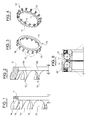
- A preferred, but not limiting embodiment of the invention will now be described, reference being made to the accompanying drawings, in which:
- figures 1 and 2 are axial cross-sectional views of a conventional ball bearing cage;
- figures 3 and 4 are perspective views showing the two opposite sides of the cage of figures 1 and 2;
- figure 5 is a partial axial cross-sectional view of a ball bearing equipped with two ball retaining cages according to figures 1-4;
- figure 6 is an axial cross-sectional view of a ball bearing equipped with two cages according to the invention;
- figures 7 and 8 are perspective views showing the two opposite sides of a cage according to the invention;
- figure 9 is a side view of the cage of figures 7 and 8; and
- figure 10 is an axial cross-sectional view taken along the line X-X in figure 9.
- Referring now to figure 6, a ball bearing unit comprises an outer
stationary race 30, two rotatableinner races balls annular cages 10 for the balls. In the example shown in figure 6, the bearing unit is of the so called I generation, i.e. having non-flanged races. Those skilled in the art will recognize that the invention is equally applicable to bearing unit of the II and III generations, with one or more flanged races. It will also be apparent that the cage of this invention may be advantageously applied also to bearings having a single row of balls (for instance the so-called "deep groove ball bearings"). - As shown in figures 7-10, each
cage 10 forms a plurality of circumferentially equally spacedcurved fingers 12 havingconcave surfaces cavities 13. Eachpocket 13 is defined by the facingsurfaces concave surfaces - Indicated P is a geometric plane tangent to the spherical surfaces S of the
pockets 13 on that side of the cage which, in the assembled condition (figure 6), is facing towards the radial mid-plane M of the bearing. - The
fingers 12 project from one side of the cage starting fromroot portions 12a joined by acircular rib 11 that constitute the radially innermost part of the annular structure of the cage and which, differently from the rib of the conventional cage show in figures 1-4, does not appreciably protrude axially beyond the tangent plane P of the spherical surfaces S. In the example shown in figures 6-10, theside 11a, herein defined "axially inner" side of therib 11, is substantially coincident with the tangential plane P. Owing to this arrangement, as can be noticed by comparing the cages of figures 1-4 and 7-10, in the cage according to the invention (figures 7-10) there are no surfaces such as those indicated 14 which concurred to define the pockets in a conventional cage. In place of thesurfaces 14, the cage according to the invention has semicircular recesses R located between twoconsecutive root portions 12a and in a radially outer position with respect to thecircular rib 11. The recesses R allow the balls of the two rows of balls to be brought axially nearer to each other. -
Reference number 17 designates optional retaining teeth that may serve to position the cages on the inner bearing races. - As will be appreciated, the new shape of the cage allows to shorten the overall axial dimension of the bearing unit. Furthermore, since the two rows of
balls - Moreover, a cage according to the invention may also be used advantageously in a bearing unit having a single row of balls. Owing to the reduced axial bulk of the cage, also the axial dimension of the bearing races can be reduced. Additionally or alternatively, the axially narrow cage of this invention leaves a free space at the side of the cage which may be used for locating an encoder or a transducer or sensor, for example, in order to detect rotation or other parameters concerning the operation of the bearing (for instance temperature, vibration, loads, humidity) or to fit a tag reporting data concerning the bearing.
Claims (6)
- A ball bearing cage (10), wherein:a plurality of circumferentially equally spaced fingers (12) extend from a first side of the cage, the fingers having concave surfaces (15, 16) forming a corresponding plurality of pockets or cavities (13) for respective balls (20 or 21),each pocket (13) being defined by the concave facing surfaces (15, 16) of two consecutive fingers (12) and being part of a substantially spherical surface (S),the fingers (12) having root portions (12a) joined by a continuous circular rib (11);characterized in that the circular rib (11)
extends circumferentially in a radially inner position with respect to the root portions (12a), and
does not axially protrude appreciably beyond a radial plane (P) tangent to the spherical surfaces (S) on a second side of the cage opposite to the first side. - A cage according to claim 1, characterized in that the circular rib (11) on the second side of the cage has a face (11a) substantially coincident with the tangential plane (P).
- A cage according to claim 1 or 2, characterized in that it has recesses (R) open in radially outward directions and located between two consecutive root portions (12a) and at a radially outer position with respect to the circular rib (11).
- A cage according to claim 3, characterized in that the recesses (R) are substantially semicircular.
- A rolling bearing having at least one row of bearing balls equipped with at last one cage according to any of claims 1 to 4.
- An angular contact ball bearing for the hub of a motor vehicle, having two rows of balls (20, 21), each row being associated with a respective cage (10) according to any of claims 1 to 4, wherein the said second sides of the two cages are facing each other.
Priority Applications (2)
| Application Number | Priority Date | Filing Date | Title |
|---|---|---|---|
| EP06112909.4A EP1847725B1 (en) | 2006-04-21 | 2006-04-21 | Comb-shaped cage for a ball row of a two row angular contact ball bearing |
| JP2007109546A JP5123554B2 (en) | 2006-04-21 | 2007-04-18 | Bearing ball cage |
Applications Claiming Priority (1)
| Application Number | Priority Date | Filing Date | Title |
|---|---|---|---|
| EP06112909.4A EP1847725B1 (en) | 2006-04-21 | 2006-04-21 | Comb-shaped cage for a ball row of a two row angular contact ball bearing |
Publications (2)
| Publication Number | Publication Date |
|---|---|
| EP1847725A1 true EP1847725A1 (en) | 2007-10-24 |
| EP1847725B1 EP1847725B1 (en) | 2015-08-12 |
Family
ID=37057105
Family Applications (1)
| Application Number | Title | Priority Date | Filing Date |
|---|---|---|---|
| EP06112909.4A Expired - Lifetime EP1847725B1 (en) | 2006-04-21 | 2006-04-21 | Comb-shaped cage for a ball row of a two row angular contact ball bearing |
Country Status (2)
| Country | Link |
|---|---|
| EP (1) | EP1847725B1 (en) |
| JP (1) | JP5123554B2 (en) |
Cited By (4)
| Publication number | Priority date | Publication date | Assignee | Title |
|---|---|---|---|---|
| CN102562787A (en) * | 2012-02-02 | 2012-07-11 | 宁波市鄞州金鑫轴承五金有限公司 | Two-raceway two-direction angular contact bearing |
| FR3003317A1 (en) * | 2013-03-18 | 2014-09-19 | Ntn Snr Roulements | CAGE RETAINING BALLS IN A BEARING BEARING |
| DE102018221608A1 (en) | 2017-12-22 | 2019-07-11 | Aktiebolaget Skf | Elastic cage for a rolling bearing |
| CN111089118A (en) * | 2018-10-24 | 2020-05-01 | 斯凯孚公司 | Bearing unit with cage |
Families Citing this family (3)
| Publication number | Priority date | Publication date | Assignee | Title |
|---|---|---|---|---|
| JP2014077508A (en) * | 2012-10-11 | 2014-05-01 | Ntn Corp | Angular ball bearing and cage used in the same |
| JP2014101922A (en) * | 2012-11-19 | 2014-06-05 | Seiko Instruments Inc | Holder, rolling bearing, bearing device and information recording and reproducing apparatus |
| KR101973943B1 (en) | 2017-05-23 | 2019-05-02 | 한국과학기술연구원 | Ball bearing |
Citations (8)
| Publication number | Priority date | Publication date | Assignee | Title |
|---|---|---|---|---|
| DE252779C (en) * | 1900-01-01 | |||
| GB216350A (en) * | 1923-06-11 | 1924-05-29 | Edward Williams | Improvements relating to ball bearings |
| US3366429A (en) * | 1965-09-13 | 1968-01-30 | Thomas L. Fawick | Bearing |
| US3980359A (en) * | 1975-05-08 | 1976-09-14 | United Technologies Corporation | Ball bearing |
| FR2665231A1 (en) | 1990-07-25 | 1992-01-31 | Roulements Soc Nouvelle | Two-part cage for a ball bearing |
| EP0592839A1 (en) * | 1992-10-15 | 1994-04-20 | SKF INDUSTRIE S.p.A. | Retention cage for the balls of rolling-contact bearings |
| DE19634483A1 (en) | 1995-09-29 | 1997-04-03 | Ntn Toyo Bearing Co Ltd | Ball bearing e.g. for head tube of steering handle in two wheeler |
| EP1132635B1 (en) | 2000-03-10 | 2004-08-11 | Snr Roulements | Ball bearing cage |
Family Cites Families (6)
| Publication number | Priority date | Publication date | Assignee | Title |
|---|---|---|---|---|
| JPS60178292U (en) * | 1984-05-08 | 1985-11-27 | 株式会社シマノ | bicycle ball bearings |
| JPH0647133Y2 (en) * | 1988-12-28 | 1994-11-30 | 光洋精工株式会社 | Double Row Outward Angular Contact Ball Bearing |
| JPH08296650A (en) * | 1995-02-28 | 1996-11-12 | Ntn Corp | Ball bearing |
| JP2998626B2 (en) * | 1996-01-16 | 2000-01-11 | 日本精工株式会社 | Synthetic resin cage for angular ball bearings |
| JP2003042161A (en) * | 2001-07-27 | 2003-02-13 | Nsk Ltd | Cages and rolling bearings |
| DE10331936B4 (en) * | 2003-07-15 | 2017-01-26 | Schaeffler Technologies AG & Co. KG | Wheel bearing unit in angular ball bearing design |
-
2006
- 2006-04-21 EP EP06112909.4A patent/EP1847725B1/en not_active Expired - Lifetime
-
2007
- 2007-04-18 JP JP2007109546A patent/JP5123554B2/en active Active
Patent Citations (8)
| Publication number | Priority date | Publication date | Assignee | Title |
|---|---|---|---|---|
| DE252779C (en) * | 1900-01-01 | |||
| GB216350A (en) * | 1923-06-11 | 1924-05-29 | Edward Williams | Improvements relating to ball bearings |
| US3366429A (en) * | 1965-09-13 | 1968-01-30 | Thomas L. Fawick | Bearing |
| US3980359A (en) * | 1975-05-08 | 1976-09-14 | United Technologies Corporation | Ball bearing |
| FR2665231A1 (en) | 1990-07-25 | 1992-01-31 | Roulements Soc Nouvelle | Two-part cage for a ball bearing |
| EP0592839A1 (en) * | 1992-10-15 | 1994-04-20 | SKF INDUSTRIE S.p.A. | Retention cage for the balls of rolling-contact bearings |
| DE19634483A1 (en) | 1995-09-29 | 1997-04-03 | Ntn Toyo Bearing Co Ltd | Ball bearing e.g. for head tube of steering handle in two wheeler |
| EP1132635B1 (en) | 2000-03-10 | 2004-08-11 | Snr Roulements | Ball bearing cage |
Cited By (6)
| Publication number | Priority date | Publication date | Assignee | Title |
|---|---|---|---|---|
| CN102562787A (en) * | 2012-02-02 | 2012-07-11 | 宁波市鄞州金鑫轴承五金有限公司 | Two-raceway two-direction angular contact bearing |
| FR3003317A1 (en) * | 2013-03-18 | 2014-09-19 | Ntn Snr Roulements | CAGE RETAINING BALLS IN A BEARING BEARING |
| DE102018221608A1 (en) | 2017-12-22 | 2019-07-11 | Aktiebolaget Skf | Elastic cage for a rolling bearing |
| CN110030272A (en) * | 2017-12-22 | 2019-07-19 | 斯凯孚公司 | Flexible retainer for rolling bearing |
| CN110030272B (en) * | 2017-12-22 | 2022-06-07 | 斯凯孚公司 | Flexible cages for rolling bearings |
| CN111089118A (en) * | 2018-10-24 | 2020-05-01 | 斯凯孚公司 | Bearing unit with cage |
Also Published As
| Publication number | Publication date |
|---|---|
| JP5123554B2 (en) | 2013-01-23 |
| JP2007292313A (en) | 2007-11-08 |
| EP1847725B1 (en) | 2015-08-12 |
Similar Documents
| Publication | Publication Date | Title |
|---|---|---|
| JP2009536998A (en) | Cage and rolling bearing assembly for ball bearing | |
| US8568035B2 (en) | Rolling bearing and cage for such a bearing | |
| JP5123554B2 (en) | Bearing ball cage | |
| US10907686B2 (en) | Flexible cage for rolling bearing | |
| JP5978578B2 (en) | Ball bearings and cages for ball bearings | |
| JP2002542436A (en) | Hard ball bearings | |
| JP2006336734A (en) | Rolling bearing with sealing device | |
| JP5272737B2 (en) | Crown type cage and ball bearing | |
| JP6511228B2 (en) | Bearings, in particular cages for bearings of automotive electrical steering systems | |
| WO2019151456A1 (en) | Ball bearing and bearing unit | |
| JP4082032B2 (en) | Ball bearing cage and ball bearing | |
| JP4147500B2 (en) | Roller bearing cage | |
| JP2020090977A (en) | Rolling bearing fixed structure | |
| JPH06511540A (en) | Cages for full rotation rolling bearings | |
| KR20010072804A (en) | Pure Rolling Bearing | |
| JP5764959B2 (en) | Ball bearing | |
| JP5499327B2 (en) | Rolling bearing | |
| JP4424092B2 (en) | Synthetic resin crown cage | |
| JP2004060701A (en) | Crowned cage for ball bearings and ball bearings incorporating the cages | |
| JP2014159846A (en) | Roller bearing and fixation device | |
| JP2012021557A (en) | Tapered roller bearing | |
| KR20200083778A (en) | Rolling bearing having improved sealing function | |
| JP5131068B2 (en) | Crown type cage | |
| JP2003254337A (en) | Synthetic resin crown type cage for radial ball bearings and radial ball bearings | |
| JP2004011667A (en) | Roller bearing and cage for the same |
Legal Events
| Date | Code | Title | Description |
|---|---|---|---|
| PUAI | Public reference made under article 153(3) epc to a published international application that has entered the european phase |
Free format text: ORIGINAL CODE: 0009012 |
|
| AK | Designated contracting states |
Kind code of ref document: A1 Designated state(s): AT BE BG CH CY CZ DE DK EE ES FI FR GB GR HU IE IS IT LI LT LU LV MC NL PL PT RO SE SI SK TR |
|
| AX | Request for extension of the european patent |
Extension state: AL BA HR MK YU |
|
| 17P | Request for examination filed |
Effective date: 20080327 |
|
| 17Q | First examination report despatched |
Effective date: 20080502 |
|
| AKX | Designation fees paid |
Designated state(s): AT BE BG CH CY CZ DE DK EE ES FI FR GB GR HU IE IS IT LI LT LU LV MC NL PL PT RO SE SI SK TR |
|
| GRAP | Despatch of communication of intention to grant a patent |
Free format text: ORIGINAL CODE: EPIDOSNIGR1 |
|
| INTG | Intention to grant announced |
Effective date: 20150311 |
|
| GRAS | Grant fee paid |
Free format text: ORIGINAL CODE: EPIDOSNIGR3 |
|
| GRAA | (expected) grant |
Free format text: ORIGINAL CODE: 0009210 |
|
| AK | Designated contracting states |
Kind code of ref document: B1 Designated state(s): AT BE BG CH CY CZ DE DK EE ES FI FR GB GR HU IE IS IT LI LT LU LV MC NL PL PT RO SE SI SK TR |
|
| REG | Reference to a national code |
Ref country code: GB Ref legal event code: FG4D |
|
| REG | Reference to a national code |
Ref country code: CH Ref legal event code: EP |
|
| REG | Reference to a national code |
Ref country code: AT Ref legal event code: REF Ref document number: 742432 Country of ref document: AT Kind code of ref document: T Effective date: 20150815 |
|
| REG | Reference to a national code |
Ref country code: IE Ref legal event code: FG4D |
|
| REG | Reference to a national code |
Ref country code: DE Ref legal event code: R096 Ref document number: 602006046232 Country of ref document: DE |
|
| REG | Reference to a national code |
Ref country code: SE Ref legal event code: TRGR |
|
| REG | Reference to a national code |
Ref country code: LT Ref legal event code: MG4D |
|
| REG | Reference to a national code |
Ref country code: AT Ref legal event code: MK05 Ref document number: 742432 Country of ref document: AT Kind code of ref document: T Effective date: 20150812 |
|
| REG | Reference to a national code |
Ref country code: NL Ref legal event code: MP Effective date: 20150812 |
|
| PG25 | Lapsed in a contracting state [announced via postgrant information from national office to epo] |
Ref country code: LT Free format text: LAPSE BECAUSE OF FAILURE TO SUBMIT A TRANSLATION OF THE DESCRIPTION OR TO PAY THE FEE WITHIN THE PRESCRIBED TIME-LIMIT Effective date: 20150812 Ref country code: LV Free format text: LAPSE BECAUSE OF FAILURE TO SUBMIT A TRANSLATION OF THE DESCRIPTION OR TO PAY THE FEE WITHIN THE PRESCRIBED TIME-LIMIT Effective date: 20150812 Ref country code: GR Free format text: LAPSE BECAUSE OF FAILURE TO SUBMIT A TRANSLATION OF THE DESCRIPTION OR TO PAY THE FEE WITHIN THE PRESCRIBED TIME-LIMIT Effective date: 20151113 Ref country code: FI Free format text: LAPSE BECAUSE OF FAILURE TO SUBMIT A TRANSLATION OF THE DESCRIPTION OR TO PAY THE FEE WITHIN THE PRESCRIBED TIME-LIMIT Effective date: 20150812 |
|
| PG25 | Lapsed in a contracting state [announced via postgrant information from national office to epo] |
Ref country code: PT Free format text: LAPSE BECAUSE OF FAILURE TO SUBMIT A TRANSLATION OF THE DESCRIPTION OR TO PAY THE FEE WITHIN THE PRESCRIBED TIME-LIMIT Effective date: 20151214 Ref country code: IS Free format text: LAPSE BECAUSE OF FAILURE TO SUBMIT A TRANSLATION OF THE DESCRIPTION OR TO PAY THE FEE WITHIN THE PRESCRIBED TIME-LIMIT Effective date: 20151212 Ref country code: ES Free format text: LAPSE BECAUSE OF FAILURE TO SUBMIT A TRANSLATION OF THE DESCRIPTION OR TO PAY THE FEE WITHIN THE PRESCRIBED TIME-LIMIT Effective date: 20150812 Ref country code: AT Free format text: LAPSE BECAUSE OF FAILURE TO SUBMIT A TRANSLATION OF THE DESCRIPTION OR TO PAY THE FEE WITHIN THE PRESCRIBED TIME-LIMIT Effective date: 20150812 Ref country code: PL Free format text: LAPSE BECAUSE OF FAILURE TO SUBMIT A TRANSLATION OF THE DESCRIPTION OR TO PAY THE FEE WITHIN THE PRESCRIBED TIME-LIMIT Effective date: 20150812 |
|
| PG25 | Lapsed in a contracting state [announced via postgrant information from national office to epo] |
Ref country code: NL Free format text: LAPSE BECAUSE OF FAILURE TO SUBMIT A TRANSLATION OF THE DESCRIPTION OR TO PAY THE FEE WITHIN THE PRESCRIBED TIME-LIMIT Effective date: 20150812 |
|
| REG | Reference to a national code |
Ref country code: FR Ref legal event code: PLFP Year of fee payment: 11 |
|
| PG25 | Lapsed in a contracting state [announced via postgrant information from national office to epo] |
Ref country code: DK Free format text: LAPSE BECAUSE OF FAILURE TO SUBMIT A TRANSLATION OF THE DESCRIPTION OR TO PAY THE FEE WITHIN THE PRESCRIBED TIME-LIMIT Effective date: 20150812 Ref country code: EE Free format text: LAPSE BECAUSE OF FAILURE TO SUBMIT A TRANSLATION OF THE DESCRIPTION OR TO PAY THE FEE WITHIN THE PRESCRIBED TIME-LIMIT Effective date: 20150812 Ref country code: CZ Free format text: LAPSE BECAUSE OF FAILURE TO SUBMIT A TRANSLATION OF THE DESCRIPTION OR TO PAY THE FEE WITHIN THE PRESCRIBED TIME-LIMIT Effective date: 20150812 Ref country code: SK Free format text: LAPSE BECAUSE OF FAILURE TO SUBMIT A TRANSLATION OF THE DESCRIPTION OR TO PAY THE FEE WITHIN THE PRESCRIBED TIME-LIMIT Effective date: 20150812 |
|
| REG | Reference to a national code |
Ref country code: DE Ref legal event code: R097 Ref document number: 602006046232 Country of ref document: DE |
|
| PG25 | Lapsed in a contracting state [announced via postgrant information from national office to epo] |
Ref country code: RO Free format text: LAPSE BECAUSE OF FAILURE TO SUBMIT A TRANSLATION OF THE DESCRIPTION OR TO PAY THE FEE WITHIN THE PRESCRIBED TIME-LIMIT Effective date: 20150812 |
|
| PLBE | No opposition filed within time limit |
Free format text: ORIGINAL CODE: 0009261 |
|
| STAA | Information on the status of an ep patent application or granted ep patent |
Free format text: STATUS: NO OPPOSITION FILED WITHIN TIME LIMIT |
|
| 26N | No opposition filed |
Effective date: 20160513 |
|
| PG25 | Lapsed in a contracting state [announced via postgrant information from national office to epo] |
Ref country code: BE Free format text: LAPSE BECAUSE OF NON-PAYMENT OF DUE FEES Effective date: 20160430 Ref country code: SI Free format text: LAPSE BECAUSE OF FAILURE TO SUBMIT A TRANSLATION OF THE DESCRIPTION OR TO PAY THE FEE WITHIN THE PRESCRIBED TIME-LIMIT Effective date: 20150812 |
|
| REG | Reference to a national code |
Ref country code: CH Ref legal event code: PL |
|
| PG25 | Lapsed in a contracting state [announced via postgrant information from national office to epo] |
Ref country code: LU Free format text: LAPSE BECAUSE OF FAILURE TO SUBMIT A TRANSLATION OF THE DESCRIPTION OR TO PAY THE FEE WITHIN THE PRESCRIBED TIME-LIMIT Effective date: 20160421 Ref country code: BE Free format text: LAPSE BECAUSE OF FAILURE TO SUBMIT A TRANSLATION OF THE DESCRIPTION OR TO PAY THE FEE WITHIN THE PRESCRIBED TIME-LIMIT Effective date: 20150812 |
|
| REG | Reference to a national code |
Ref country code: IE Ref legal event code: MM4A |
|
| PG25 | Lapsed in a contracting state [announced via postgrant information from national office to epo] |
Ref country code: LI Free format text: LAPSE BECAUSE OF NON-PAYMENT OF DUE FEES Effective date: 20160430 Ref country code: CH Free format text: LAPSE BECAUSE OF NON-PAYMENT OF DUE FEES Effective date: 20160430 |
|
| REG | Reference to a national code |
Ref country code: FR Ref legal event code: PLFP Year of fee payment: 12 |
|
| PG25 | Lapsed in a contracting state [announced via postgrant information from national office to epo] |
Ref country code: IE Free format text: LAPSE BECAUSE OF NON-PAYMENT OF DUE FEES Effective date: 20160421 |
|
| REG | Reference to a national code |
Ref country code: FR Ref legal event code: PLFP Year of fee payment: 13 |
|
| PG25 | Lapsed in a contracting state [announced via postgrant information from national office to epo] |
Ref country code: CY Free format text: LAPSE BECAUSE OF FAILURE TO SUBMIT A TRANSLATION OF THE DESCRIPTION OR TO PAY THE FEE WITHIN THE PRESCRIBED TIME-LIMIT Effective date: 20150812 Ref country code: HU Free format text: LAPSE BECAUSE OF FAILURE TO SUBMIT A TRANSLATION OF THE DESCRIPTION OR TO PAY THE FEE WITHIN THE PRESCRIBED TIME-LIMIT; INVALID AB INITIO Effective date: 20060421 |
|
| PG25 | Lapsed in a contracting state [announced via postgrant information from national office to epo] |
Ref country code: TR Free format text: LAPSE BECAUSE OF FAILURE TO SUBMIT A TRANSLATION OF THE DESCRIPTION OR TO PAY THE FEE WITHIN THE PRESCRIBED TIME-LIMIT Effective date: 20150812 Ref country code: MC Free format text: LAPSE BECAUSE OF FAILURE TO SUBMIT A TRANSLATION OF THE DESCRIPTION OR TO PAY THE FEE WITHIN THE PRESCRIBED TIME-LIMIT Effective date: 20150812 |
|
| PG25 | Lapsed in a contracting state [announced via postgrant information from national office to epo] |
Ref country code: BG Free format text: LAPSE BECAUSE OF FAILURE TO SUBMIT A TRANSLATION OF THE DESCRIPTION OR TO PAY THE FEE WITHIN THE PRESCRIBED TIME-LIMIT Effective date: 20150812 |
|
| P01 | Opt-out of the competence of the unified patent court (upc) registered |
Effective date: 20230513 |
|
| PGFP | Annual fee paid to national office [announced via postgrant information from national office to epo] |
Ref country code: DE Payment date: 20250428 Year of fee payment: 20 |
|
| PGFP | Annual fee paid to national office [announced via postgrant information from national office to epo] |
Ref country code: GB Payment date: 20250422 Year of fee payment: 20 |
|
| PGFP | Annual fee paid to national office [announced via postgrant information from national office to epo] |
Ref country code: IT Payment date: 20250422 Year of fee payment: 20 |
|
| PGFP | Annual fee paid to national office [announced via postgrant information from national office to epo] |
Ref country code: FR Payment date: 20250424 Year of fee payment: 20 |
|
| PGFP | Annual fee paid to national office [announced via postgrant information from national office to epo] |
Ref country code: SE Payment date: 20250424 Year of fee payment: 20 |
|
| REG | Reference to a national code |
Ref country code: DE Ref legal event code: R082 Ref document number: 602006046232 Country of ref document: DE Representative=s name: SCHONECKE, MITJA, DIPL.-PHYS. DR. RER. NAT., DE Ref country code: DE Ref legal event code: R082 Ref document number: 602006046232 Country of ref document: DE Representative=s name: SCHONECKE, MITJA, DR., DE |
|
| REG | Reference to a national code |
Ref country code: DE Ref legal event code: R082 Ref document number: 602006046232 Country of ref document: DE Representative=s name: SCHONECKE, MITJA, DR., DE |
|
| REG | Reference to a national code |
Ref country code: DE Ref legal event code: R071 Ref document number: 602006046232 Country of ref document: DE |
|
| REG | Reference to a national code |
Ref country code: GB Ref legal event code: PE20 Expiry date: 20260420 |
|
| PG25 | Lapsed in a contracting state [announced via postgrant information from national office to epo] |
Ref country code: GB Free format text: LAPSE BECAUSE OF EXPIRATION OF PROTECTION Effective date: 20260420 |