EP1847440A1 - Steering column assembly for a vehicle - Google Patents
Steering column assembly for a vehicle Download PDFInfo
- Publication number
- EP1847440A1 EP1847440A1 EP07075227A EP07075227A EP1847440A1 EP 1847440 A1 EP1847440 A1 EP 1847440A1 EP 07075227 A EP07075227 A EP 07075227A EP 07075227 A EP07075227 A EP 07075227A EP 1847440 A1 EP1847440 A1 EP 1847440A1
- Authority
- EP
- European Patent Office
- Prior art keywords
- steering column
- column assembly
- bracket
- bore
- set forth
- Prior art date
- Legal status (The legal status is an assumption and is not a legal conclusion. Google has not performed a legal analysis and makes no representation as to the accuracy of the status listed.)
- Withdrawn
Links
- 238000009434 installation Methods 0.000 claims abstract description 7
- 238000006073 displacement reaction Methods 0.000 claims description 5
- 238000003780 insertion Methods 0.000 claims description 2
- 230000037431 insertion Effects 0.000 claims description 2
- 230000001050 lubricating effect Effects 0.000 claims description 2
- 239000004033 plastic Substances 0.000 claims description 2
- 230000000712 assembly Effects 0.000 description 2
- 238000000429 assembly Methods 0.000 description 2
- 238000004519 manufacturing process Methods 0.000 description 2
- 238000012986 modification Methods 0.000 description 2
- 230000004048 modification Effects 0.000 description 2
- 238000013461 design Methods 0.000 description 1
- 238000002347 injection Methods 0.000 description 1
- 239000007924 injection Substances 0.000 description 1
- 239000000314 lubricant Substances 0.000 description 1
- 238000012423 maintenance Methods 0.000 description 1
- 239000002184 metal Substances 0.000 description 1
- 238000000034 method Methods 0.000 description 1
- 239000002991 molded plastic Substances 0.000 description 1
- 230000002093 peripheral effect Effects 0.000 description 1
Images


Classifications
-
- B—PERFORMING OPERATIONS; TRANSPORTING
- B62—LAND VEHICLES FOR TRAVELLING OTHERWISE THAN ON RAILS
- B62D—MOTOR VEHICLES; TRAILERS
- B62D1/00—Steering controls, i.e. means for initiating a change of direction of the vehicle
- B62D1/02—Steering controls, i.e. means for initiating a change of direction of the vehicle vehicle-mounted
- B62D1/16—Steering columns
- B62D1/18—Steering columns yieldable or adjustable, e.g. tiltable
- B62D1/187—Steering columns yieldable or adjustable, e.g. tiltable with tilt adjustment; with tilt and axial adjustment
- B62D1/189—Steering columns yieldable or adjustable, e.g. tiltable with tilt adjustment; with tilt and axial adjustment the entire column being tiltable as a unit
Definitions
- the present invention relates to a steering column assembly for a vehicle and more particularly to an adjustable steering column assembly.
- Steering column assemblies are know to have a rotating shaft connected at one end to a steering wheel and at an opposite end supported by a bracket carrying a bearing race for smooth rotation of the shaft.
- the rotating shafts typically have a non-rotating jacket sleeve co-extending concentrically with the rotating shaft and spaced radially outward therefrom.
- the bracket is support pivotally by a vehicle structure.
- the pivot joint carried between the bracket and structure has many individual parts and are known to include a separate pin or bolt that must be threaded through a series of holes in both the bracket and the structure. The bolt is secured in place by a threaded nut and a series of washers along its length. Unfortunately, the numerous parts and time consuming assembly of the joint increases manufacturing costs.
- the jacket sleeve must be rigidly engaged to the bracket so that it is held stationary relative to the shaft and regardless of the steering wheel's tilted position.
- a plurality of pins or threaded fasteners with corresponding holes in both the sleeve and the bracket are used to fasten the sleeve to the bracket. The excessive parts again leads to relatively high manufacturing costs.
- An adjustable steering column assembly for a vehicle has an integral rake pivot joint carried between a mounting structure generally attached to the vehicle chassis and a support bracket that pivots about a pivot axis.
- a preferably telescoping shaft extends along a centerline and connects to a steering wheel at a first end and is rotationally supported near an opposite second end by the support bracket.
- the pivot axis is orientated substantially parallel to the centerline.
- the pivot joint has a boss preferably elongated with respect to the pivot axis and generally orientated concentrically to the pivot axis.
- the boss fits pivotally in a bore disposed concentrically to the pivot axis and carried by the other of the mounting structure and support bracket.
- a web portion of the boss projects through a slit extending axially and communicating radially inward with the bore.
- the support bracket has a through-bore disposed concentrically to the centerline through which the telescoping shaft extends and the second end of the shaft projects in a forward direction with respect to the vehicle.
- a bearing adaptor fits into a forward portion of the through bore for rotatably supporting the second end of the telescoping shaft.
- a rearward projecting jacket sleeve of the steering column assembly snap fits into a rearward portion of the through-bore and projects concentrically rearward along the centerline with the rotating shaft spaced radially inward.
- Objects, features and advantages of the present invention include an adjustable steering column assembly having self lubricating rake pivot joint that is integrated into existing structures. This, and the snap fitting jacket sleeve reduce the number of parts otherwise required for assembly and simplify the assembly process of the steering column assembly. Other advantages include a robust design requiring little or no maintenance and in service has a long and useful life.
- an adjustable steering column assembly 20 used for a vehicle and embodying the present invention and for a vehicle, has a tilt feature and preferably a telescoping feature that adjusts positioning of a steering wheel (not shown) for driver convenience and comfort.
- the steering column assembly 20 has a preferably stationary mounting structure 22 connected pivotally to a support bracket 24.
- the support bracket 24 rotatably supports a forward end 28 (with respect to the vehicle) of a preferably telescoping shaft 26 that extends rearward to a rearward end 30 connected to the steering wheel.
- a support mechanism 36 having a control lever 38 is supported by the mounting structure 22 rearward of the support bracket 24 and lockably controls and restricts adjustment or repositioning of the telescoping shaft 26 and jacket sleeves 32, 34.
- the mounting structure 22 of the steering column assembly 20 is preferably fastened to a chassis or underneath a dash of the vehicle by a plurality of threaded fasteners or bolts (not shown) and preferably with respective bushings located between the chassis and structure 22 to reduce the amount of vibration that could otherwise be transmitted to the steering column assembly 20.
- the structure 22 is generally U-shaped having two substantially parallel legs 40, 42 projecting rearward and substantially horizontally from a base member 44 that pivotally connects to the support bracket 24.
- a generally U-shaped housing 45 of the support mechanism 36 is orientated in an upright position and has two parallel walls 47, 49 that hang or are connected to the respective legs 40, 42 of the mounting structure 22.
- the telescoping shaft 26 and the sleeves 32, 34 extend through the housing 45 between the walls 47, 49 and lie substantially parallel to and at least in part below the legs 40, 42.
- the support bracket 24 of the steering column assembly 20 is preferably suspended pivotally from the base member 44 of the mounting structure 22 along a pivot axis 46.
- the shaft 26 projects concentrically through a through-bore 48 in the support bracket 24 and along a centerline 50 orientated substantially perpendicular to and spaced from the pivot axis 46.
- a bearing adaptor or race 52 is press fitted into a forward portion or opening 54 of the through-bore 48 for rotatably supporting the forward end 28 of the shaft 26 and preferably axially retaining the shaft 26 with respect to the centerline 50.
- a rearward portion or opening 56 of the through-bore 48 in the support bracket 24 receives the front sleeve 32.
- the rearward portion 56 communicates radially outward with four circumferentially spaced and axially extending channels 58.
- Substantially located in each channel 58 is a resiliently flexible lock arm 60 of the support bracket 24 that projects in a rearward direction to an enlarged distal head 62 of the arm 60 for snap locking to the front sleeve 32.
- the enlarged head 62 projects at least in-part radially inward into the rearward portion 56 of the through-bore 48 and is spaced radially inward from the bottom of the channels 58 carried by the support bracket 24.
- the front sleeve 32 is preferably substantially cylindrical having an outer diameter that is slightly less than an inner diameter of the rear sleeve 34 (i.e. rearward with respect to the vehicle).
- a forward end 28 of the front sleeve 32 has a continuous peripheral edge 64 and preferable four recesses or holes 66 located rearward of the edge 64.
- the holes 66 are opened at least radially inward and spaced circumferentially about the sleeve 32 to align with the enlarged heads 62 of the lock arms 60 when the front sleeve 32 is snap fitted to the support bracket 24.
- a rack pivot joint 68 pivotally engages the support bracket 24 to the base member 44 of the mounting structure 22 and about the pivot axis 46.
- the pivot joint 68 does not have any dedicated individually separated parts, and instead is completely integrated and carried between the support bracket 24 and the base member 44.
- the pivot joint 68 has a boss 70 preferably formed to the support bracket 24 and elongated axially with respect to the pivot axis 46.
- the boss 70 has a substantially cylindrical pin 72 disposed concentrically to the pivot axis 46 and a co-extending web 74 that projects laterally outward from a substantially planar exterior face 76 carried by the support bracket 24 and located above the through-bore 48.
- the pin 72 carries a substantially cylindrical convex surface 78 that is contiguous to the exterior face 76 at the web 74.
- the convex surface 78 angularly extends circumferentially about the pivot axis 46 by an amount greater than one-hundred and eighty degrees from one side of the web 74 to the other.
- the pin 72 of the boss 70 is received in a bore 80 of the rack pivot joint 68 in the base member 44 of the mounting structure 22 (see Figure 3).
- the bore 80 has an open end 82 for axial receipt of the pin 72.
- a slit 84 in the base member 44 of the mounting structure 22 extends axially with respect to the pivot axis 46 and communicates radially inward with the bore 80 for receipt of the web 74.
- the web 74 projects laterally through the slit 84 and forms to the pin 72 disposed rotatably in the bore 80.
- the bore 80 is generally defined by a substantially cylindrical concave surface 86 carried by the base member 44 and angularly extending circumferentially greater than one-hundred and eighty degrees for suspending the support bracket 24 from the mounting structure 22.
- the convex surface 78 of the pin 72 preferably defines at least one axial extending groove 88 that distributes lubricant between surfaces 78, 86 for substantially friction-free pivoting.
- the concave surface 86 extends circumferentially at a greater angular distance than the convex surface 78 of the pin 72 of the boss 70.
- the support bracket 24 and thus the steering wheel is constructed to pivot or tilt by an amount of about fifteen degrees.
- the width of the slit 84 must therefore be greater than the thickness of the web 74 by a circumferential distance equating to greater than fifteen degrees.
- the support bracket 24 is preferably made of injection molded plastic and as one unitary piece with the resilient lock arms 60.
- the front sleeve 32 is preferably made of metal for rigidity.
- the boss 70 of the rake pivot joint 68 could be in the support bracket 24 and the boss 70 formed to the mounting structure 22.
- the boss 70 need not have an elongated pin 72 but instead could carry an enlarged and generally spherical head thus altering the pivot axis 46 to a pivot point.
- a modification of the rake pivot joint 68' is illustrated wherein a pin 72' formed unitary to a support bracket 24' is inserted radially into a bore 80' in a mounting structure 22' and with respect to a pivot axis 46'.
- a substantially cylindrical convex surface 78' of a pin 72' has a substantially planar portion 90 that extends axially with respect to the pivot axis 46'.
- the diametric distance of the pin 72' from the planar portion 90 and through the pivot axis 46' is equal to or slightly less than the width of the slit 84' that communicates radially inward to the bore 80'. Consequently, when support bracket 24' is orientated at a pre-specified, angular, installation position 92 the pin 72' can be raised laterally into the bore 80' through the slit 84'. Because full tilt down and full tilt up positions 94, 96 do not correspond to the angular alignment of the installation position 92, the rake pivot joint 68' will remain coupled.
- the convex surface 78' is substantially cylindrical and concentric with respect to pivot axis 46'.
- the convex surface 78' has a first cylindrical portion 98 that extends circumferentially from the web 74' and in a counter-clockwise direction to a first point or axially extending apex 100. From the first apex 100 the substantially planar or non-concave portion 90 spans laterally with respect to the pivot axis 46' to a second apex 102.
- a second cylindrical portion 104 extends circumferentially in the counter-clockwise direction from the second point or apex 102 to the web 74'.
- the first and second apexes 100, 102 both lie in an imaginary plane 104 with the planar portion 90 that is spaced from and parallel to the pivot axis 46'.
- An opposite imaginary plane 106 located tangentially to the first cylindrical portion 98 is parallel to the first imaginary plane 104 and spaced by a distance 108 that is measured generally through the pivot axis 46'.
- the radial distance 108 of the pin 72' is preferably slightly less than a width 110 of the slit 84' of the bore 80'.
- the radial distance 108 could be equal to or even slightly greater than the width 110 thus enabling a snap fit engagement.
- any such snap fit engagement should not cause plastic deformation of either the structure 22' or the bracket 24' that could potentially hinder pivotal movement.
- the bracket 24' pivots at a maximum angular displacement, represented as arrow 112 in Figure 8.
- This angular displacement 112 is less than the angular distance, represented as arrow 114 that represents the circumferential spanning of the second cylindrical portion 104 from the web 74' to the second apex 102.
- angular displacement 112 is less than angular distance 114, release of the support bracket 24' from the mounting structure 22' after assembly of the steering column assembly 20' and during tilt operation.
- the support mechanism 36 provides the necessary stops for the tilt down and up positions 94, 96.
- the stop or contact relationship can be carried directly between the mounting structure 22' and the support bracket 25'.
Landscapes
- Engineering & Computer Science (AREA)
- Chemical & Material Sciences (AREA)
- Combustion & Propulsion (AREA)
- Transportation (AREA)
- Mechanical Engineering (AREA)
- Steering Controls (AREA)
Abstract
Description
- The present invention relates to a steering column assembly for a vehicle and more particularly to an adjustable steering column assembly.
- Steering column assemblies are know to have a rotating shaft connected at one end to a steering wheel and at an opposite end supported by a bracket carrying a bearing race for smooth rotation of the shaft. The rotating shafts typically have a non-rotating jacket sleeve co-extending concentrically with the rotating shaft and spaced radially outward therefrom. For steering column assemblies known to have a tilt adjustment feature, the bracket is support pivotally by a vehicle structure. The pivot joint carried between the bracket and structure has many individual parts and are known to include a separate pin or bolt that must be threaded through a series of holes in both the bracket and the structure. The bolt is secured in place by a threaded nut and a series of washers along its length. Unfortunately, the numerous parts and time consuming assembly of the joint increases manufacturing costs.
- Moreover, and particularly for telescoping shaft applications, the jacket sleeve must be rigidly engaged to the bracket so that it is held stationary relative to the shaft and regardless of the steering wheel's tilted position. Typically, a plurality of pins or threaded fasteners with corresponding holes in both the sleeve and the bracket are used to fasten the sleeve to the bracket. The excessive parts again leads to relatively high manufacturing costs.
- An adjustable steering column assembly for a vehicle has an integral rake pivot joint carried between a mounting structure generally attached to the vehicle chassis and a support bracket that pivots about a pivot axis. A preferably telescoping shaft extends along a centerline and connects to a steering wheel at a first end and is rotationally supported near an opposite second end by the support bracket. Preferably, the pivot axis is orientated substantially parallel to the centerline. The pivot joint has a boss preferably elongated with respect to the pivot axis and generally orientated concentrically to the pivot axis. The boss fits pivotally in a bore disposed concentrically to the pivot axis and carried by the other of the mounting structure and support bracket. A web portion of the boss projects through a slit extending axially and communicating radially inward with the bore.
- Preferably, the support bracket has a through-bore disposed concentrically to the centerline through which the telescoping shaft extends and the second end of the shaft projects in a forward direction with respect to the vehicle. A bearing adaptor fits into a forward portion of the through bore for rotatably supporting the second end of the telescoping shaft. Preferably, a rearward projecting jacket sleeve of the steering column assembly snap fits into a rearward portion of the through-bore and projects concentrically rearward along the centerline with the rotating shaft spaced radially inward.
- Objects, features and advantages of the present invention include an adjustable steering column assembly having self lubricating rake pivot joint that is integrated into existing structures. This, and the snap fitting jacket sleeve reduce the number of parts otherwise required for assembly and simplify the assembly process of the steering column assembly. Other advantages include a robust design requiring little or no maintenance and in service has a long and useful life.
- Other advantages of the present invention will be readily appreciated as the same becomes better understood by reference to the following detailed description when considered in connection with the accompanying drawings wherein:
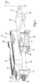
- Figure 1 is a perspective view of a steering column assembly embodying the present invention;
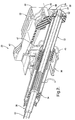
- Figure 2 is a perspective cross section view of the steering column assembly taken along line 2-2 of Figure 1;
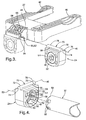
- Figure 3 is an exploded perspective view of a mounting bracket and support bracket of the steering column assembly;
- Figure 4 is an exploded perspective view of the support bracket and a jacket sleeve of the steering column assembly;
- Figure 5 is a partial exploded side view of a modified steering column assembly;
- Figure 6 is a partial side view of the modified steering column assembly illustrating a down position;
- Figure 7 is a partial side view of the modified steering column assembly illustrating an up position; and
- Figure 8 is an enlarged side view of the modified steering column assembly of Figure 5.
- Referring to the Figures, wherein like numerals indicate like or corresponding parts throughout the several views, an adjustable
steering column assembly 20 used for a vehicle and embodying the present invention and for a vehicle, has a tilt feature and preferably a telescoping feature that adjusts positioning of a steering wheel (not shown) for driver convenience and comfort. As best illustrated in Figures 1 and 2, thesteering column assembly 20 has a preferablystationary mounting structure 22 connected pivotally to asupport bracket 24. Thesupport bracket 24 rotatably supports a forward end 28 (with respect to the vehicle) of a preferably telescopingshaft 26 that extends rearward to arearward end 30 connected to the steering wheel. Spaced radially outward from thetelescoping shaft 26 are axially overlapping front andrear jacket sleeves front sleeve 32 snap fits to and rigidly projects rearward from thesupport bracket 24. Asupport mechanism 36 having acontrol lever 38 is supported by themounting structure 22 rearward of thesupport bracket 24 and lockably controls and restricts adjustment or repositioning of thetelescoping shaft 26 andjacket sleeves - The
mounting structure 22 of thesteering column assembly 20 is preferably fastened to a chassis or underneath a dash of the vehicle by a plurality of threaded fasteners or bolts (not shown) and preferably with respective bushings located between the chassis andstructure 22 to reduce the amount of vibration that could otherwise be transmitted to thesteering column assembly 20. Thestructure 22 is generally U-shaped having two substantiallyparallel legs base member 44 that pivotally connects to thesupport bracket 24. A generally U-shapedhousing 45 of thesupport mechanism 36 is orientated in an upright position and has twoparallel walls respective legs mounting structure 22. Thetelescoping shaft 26 and thesleeves housing 45 between thewalls legs - As best illustrated in Figures 2-4, the
support bracket 24 of thesteering column assembly 20 is preferably suspended pivotally from thebase member 44 of themounting structure 22 along apivot axis 46. Theshaft 26 projects concentrically through a through-bore 48 in thesupport bracket 24 and along acenterline 50 orientated substantially perpendicular to and spaced from thepivot axis 46. A bearing adaptor orrace 52 is press fitted into a forward portion or opening 54 of the through-bore 48 for rotatably supporting theforward end 28 of theshaft 26 and preferably axially retaining theshaft 26 with respect to thecenterline 50. - As best illustrated in Figure 4, a rearward portion or opening 56 of the through-
bore 48 in thesupport bracket 24 receives thefront sleeve 32. Therearward portion 56 communicates radially outward with four circumferentially spaced and axially extendingchannels 58. Substantially located in eachchannel 58 is a resilientlyflexible lock arm 60 of thesupport bracket 24 that projects in a rearward direction to an enlargeddistal head 62 of thearm 60 for snap locking to thefront sleeve 32. When thelock arm 60 is in an un-flexed or natural state, the enlargedhead 62 projects at least in-part radially inward into therearward portion 56 of the through-bore 48 and is spaced radially inward from the bottom of thechannels 58 carried by thesupport bracket 24. - The
front sleeve 32 is preferably substantially cylindrical having an outer diameter that is slightly less than an inner diameter of the rear sleeve 34 (i.e. rearward with respect to the vehicle). Aforward end 28 of thefront sleeve 32 has a continuousperipheral edge 64 and preferable four recesses orholes 66 located rearward of theedge 64. Theholes 66 are opened at least radially inward and spaced circumferentially about thesleeve 32 to align with the enlargedheads 62 of thelock arms 60 when thefront sleeve 32 is snap fitted to thesupport bracket 24. - A
rack pivot joint 68 pivotally engages thesupport bracket 24 to thebase member 44 of themounting structure 22 and about thepivot axis 46. Preferably, thepivot joint 68 does not have any dedicated individually separated parts, and instead is completely integrated and carried between thesupport bracket 24 and thebase member 44. As best shown in Figures 3 and 4, thepivot joint 68 has aboss 70 preferably formed to thesupport bracket 24 and elongated axially with respect to thepivot axis 46. - The
boss 70 has a substantiallycylindrical pin 72 disposed concentrically to thepivot axis 46 and aco-extending web 74 that projects laterally outward from a substantially planarexterior face 76 carried by thesupport bracket 24 and located above the through-bore 48. Thepin 72 carries a substantially cylindricalconvex surface 78 that is contiguous to theexterior face 76 at theweb 74. Theconvex surface 78 angularly extends circumferentially about thepivot axis 46 by an amount greater than one-hundred and eighty degrees from one side of theweb 74 to the other. - During assembly, the
pin 72 of theboss 70 is received in abore 80 of therack pivot joint 68 in thebase member 44 of the mounting structure 22 (see Figure 3). Preferably, thebore 80 has an open end 82 for axial receipt of thepin 72. Aslit 84 in thebase member 44 of themounting structure 22 extends axially with respect to thepivot axis 46 and communicates radially inward with thebore 80 for receipt of theweb 74. Thus, when fully assembled, theweb 74 projects laterally through theslit 84 and forms to thepin 72 disposed rotatably in thebore 80. Thebore 80 is generally defined by a substantially cylindricalconcave surface 86 carried by thebase member 44 and angularly extending circumferentially greater than one-hundred and eighty degrees for suspending thesupport bracket 24 from the mountingstructure 22. - The
convex surface 78 of thepin 72 preferably defines at least one axial extendinggroove 88 that distributes lubricant betweensurfaces support bracket 24 from falling out of thebore 80 in thebase member 44 of the mountingstructure 22, theconcave surface 86 extends circumferentially at a greater angular distance than theconvex surface 78 of thepin 72 of theboss 70. Preferably, thesupport bracket 24 and thus the steering wheel is constructed to pivot or tilt by an amount of about fifteen degrees. The width of theslit 84 must therefore be greater than the thickness of theweb 74 by a circumferential distance equating to greater than fifteen degrees. - The
support bracket 24 is preferably made of injection molded plastic and as one unitary piece with theresilient lock arms 60. Thefront sleeve 32 is preferably made of metal for rigidity. One skilled in the art would now know that various elements of the invention can be reversed. For instance, theboss 70 of the rake pivot joint 68 could be in thesupport bracket 24 and theboss 70 formed to the mountingstructure 22. Moreover, theboss 70 need not have an elongatedpin 72 but instead could carry an enlarged and generally spherical head thus altering thepivot axis 46 to a pivot point. - Referring to Figures 5-8 where similar elements of
assembly 20 are identified with like numerals and with the addition of a prime symbol, a modification of the rake pivot joint 68' is illustrated wherein a pin 72' formed unitary to a support bracket 24' is inserted radially into abore 80' in a mounting structure 22' and with respect to apivot axis 46'. To enable this radial insertion, a substantially cylindrical convex surface 78' of a pin 72' has a substantiallyplanar portion 90 that extends axially with respect to thepivot axis 46'. The diametric distance of the pin 72' from theplanar portion 90 and through thepivot axis 46' is equal to or slightly less than the width of the slit 84' that communicates radially inward to thebore 80'. Consequently, when support bracket 24' is orientated at a pre-specified, angular,installation position 92 the pin 72' can be raised laterally into thebore 80' through the slit 84'. Because full tilt down and full tilt uppositions installation position 92, the rake pivot joint 68' will remain coupled. - As best illustrated in Figure 8, the convex surface 78' is substantially cylindrical and concentric with respect to pivot
axis 46'. The convex surface 78' has a firstcylindrical portion 98 that extends circumferentially from the web 74' and in a counter-clockwise direction to a first point or axially extendingapex 100. From thefirst apex 100 the substantially planar ornon-concave portion 90 spans laterally with respect to thepivot axis 46' to asecond apex 102. A secondcylindrical portion 104 extends circumferentially in the counter-clockwise direction from the second point or apex 102 to the web 74'. Although one skilled in the art would now know that theplanar portion 90 could be concave, the first andsecond apexes imaginary plane 104 with theplanar portion 90 that is spaced from and parallel to thepivot axis 46'. An oppositeimaginary plane 106 located tangentially to the firstcylindrical portion 98 is parallel to the firstimaginary plane 104 and spaced by adistance 108 that is measured generally through thepivot axis 46'. - So that the pin 72' of the boss 70' can be inserted radially into the
bore 80', theradial distance 108 of the pin 72' is preferably slightly less than awidth 110 of the slit 84' of thebore 80'. Alternatively, theradial distance 108 could be equal to or even slightly greater than thewidth 110 thus enabling a snap fit engagement. However, any such snap fit engagement should not cause plastic deformation of either the structure 22' or the bracket 24' that could potentially hinder pivotal movement. - When the steering column assembly 20' pivots between the tilt down and tilt up
positions arrow 112 in Figure 8. Thisangular displacement 112 is less than the angular distance, represented asarrow 114 that represents the circumferential spanning of the secondcylindrical portion 104 from the web 74' to thesecond apex 102. Becauseangular displacement 112 is less thanangular distance 114, release of the support bracket 24' from the mounting structure 22' after assembly of the steering column assembly 20' and during tilt operation. Preferably, thesupport mechanism 36 provides the necessary stops for the tilt down and uppositions position 96, the stop or contact relationship can be carried directly between the mounting structure 22' and the support bracket 25'. - The invention has been described in an illustrative manner, and it is to be understood that the terminology which has been used is intended to be in the nature of words of description rather than of limitation. For instance, orientation of components with respect to the vehicle can be changed from "forward" and "rearward" to "lower" and "upper". As is now apparent to those skilled in the art, many modifications and variations of the present invention are possible in light of the above teachings. It is, therefore, to be understood that within the scope of the appended claims, wherein reference numerals are merely for convenience and are not to be in any way limiting, the invention may be practiced otherwise than as specifically described.
Claims (15)
- An adjustable steering column assembly (20') for a vehicle comprising:a structure (22');a bracket (24') having an angular installation position (92), a tilt down position (94) and a tilt up position (96) with respect to a pivot axis (46'), wherein angular installation position is not located between the tilt down and tilt up positions;a pivot joint (68') having an axially extending bore (80') having an axially extending and narrowed slit (84') both located in one of the structure and the bracket, and an axially extending boss (70') projecting unitarily outward from the other of the structure and the bracket as one piece, wherein the boss extends radially through the slit and is disposed substantially in the bore for movement of the bracket about the pivot axis and with respect to the structure; andwherein the boss is inserted through the slit and into the bore when in the angular installation position.
- The adjustable steering column assembly set forth in claim 1 further comprising:an axially elongated web (74') of the boss projecting laterally outward from the other of the structure and the bracket and projecting through the slit; andan axially elongated pin (72') of the boss attached and enlarged with respect to the web and located rotatably in the bore.
- The adjustable steering column assembly set forth in claim 2 wherein the structure is stationary with respect to the vehicle.
- The adjustable steering column assembly set forth in claim 3 wherein the bore is in the structure and the web projects laterally from the bracket.
- The adjustable steering column assembly set forth in claim 4 wherein the bracket is suspended from the structure by the pivot joint when not in the angular installation position.
- The adjustable steering column assembly set forth in claim 5 wherein the pin carries a surface (78') having first cylindrical portion (98) extending circumferentially counter-clockwise from the web, a second cylindrical portion (104) extending clockwise from the web, and a non-convex portion (90) disposed circumferentially between the first and second cylindrical portions.
- The adjustable steering column assembly set forth in claim 6 further comprising:the non-convex portion generally lying in a first imaginary plane (104) disposed parallel to the pivot axis;a second imaginary plane (106) orientated tangentially to the first cylindrical portion and disposed parallel to the first imaginary plane;a radial distance (108) measured between the first and second imaginary planes and through the pivot axis; anda width (110) of the slit being slightly greater than the radial distance.
- The adjustable steering column assembly set forth in claim 7 further comprising:the second cylindrical portion extending circumferentially by an angular distance (114); andan angular displacement (112) measured between the tilt down and tilt up positions and with respect to the pivot axis, wherein the angular displacement is less than the angular distance.
- The adjustable steering column assembly set forth in claim 2 further comprising at least one axially extending groove (88) in the pin and communicating laterally with the bore for lubricating the pivot joint.
- The adjustable steering column assembly set forth in claim 1 further comprising:a through-bore (48) in the bracket having a centerline (50) orientated perpendicular to the pivot axis; anda jacket sleeve (32) projecting outward from the bracket and disposed concentrically to the centerline.
- The adjustable steering column assembly set forth in claim 10 wherein the sleeve snap fits to the bracket.
- The adjustable steering column assembly set forth in claim 11 wherein the sleeve snap fits to the bracket in the through-bore.
- The adjustable steering column assembly set forth in claim 12 further comprising a bearing race (52) supported by the bracket in the through-bore and disposed concentrically to the centerline.
- The adjustable steering column assembly set forth in claim 12 further comprising:at least one flexible lock arm (60) of the bracket disposed in the through-bore; andat least one recess (66) in the sleeve opened at least radially outward with respect to the centerline for snap fitting receipt of the at least one lock arm.
- The adjustable steering column assembly set forth in claim 1 wherein the boss snap fits to one of the structure and the bracket during radial insertion into the bore and without causing plastic deformation.
Applications Claiming Priority (1)
| Application Number | Priority Date | Filing Date | Title |
|---|---|---|---|
| US11/407,453 US20070245845A1 (en) | 2006-04-20 | 2006-04-20 | Steering column assembly for a vehicle |
Publications (1)
| Publication Number | Publication Date |
|---|---|
| EP1847440A1 true EP1847440A1 (en) | 2007-10-24 |
Family
ID=38171650
Family Applications (1)
| Application Number | Title | Priority Date | Filing Date |
|---|---|---|---|
| EP07075227A Withdrawn EP1847440A1 (en) | 2006-04-20 | 2007-03-26 | Steering column assembly for a vehicle |
Country Status (2)
| Country | Link |
|---|---|
| US (1) | US20070245845A1 (en) |
| EP (1) | EP1847440A1 (en) |
Cited By (3)
| Publication number | Priority date | Publication date | Assignee | Title |
|---|---|---|---|---|
| KR20150142395A (en) * | 2014-06-12 | 2015-12-22 | 주식회사 만도 | Steering Column for Vehicle |
| WO2016110336A1 (en) * | 2015-01-08 | 2016-07-14 | Thyssenkrupp Presta Ag | Steering column having an adaptable pivot support |
| WO2017076858A1 (en) * | 2015-11-05 | 2017-05-11 | Thyssenkrupp Presta Ag | Pivot bearings for a height-adjustable steering column |
Families Citing this family (3)
| Publication number | Priority date | Publication date | Assignee | Title |
|---|---|---|---|---|
| DE102004045876B4 (en) * | 2004-09-20 | 2006-07-06 | Delphi Technologies, Inc., Troy | Fastening device for a steering column module of a motor vehicle |
| DE102015000027A1 (en) * | 2015-01-08 | 2016-07-14 | Thyssenkrupp Ag | Steering column with flexibly mountable bearing seat |
| US10532761B2 (en) * | 2017-12-06 | 2020-01-14 | Thyssenkrupp Presta Ag | Spindle and steering column assembly having same |
Citations (5)
| Publication number | Priority date | Publication date | Assignee | Title |
|---|---|---|---|---|
| JPH09109899A (en) * | 1995-10-18 | 1997-04-28 | Nippon Seiko Kk | Steering wheel support device |
| EP0866230A1 (en) * | 1997-03-19 | 1998-09-23 | Ecia - Equipements Et Composants Pour L'industrie Automobile | Fastening device for attaching one part to another |
| US20040231450A1 (en) * | 2002-12-25 | 2004-11-25 | Fuji Kiko Co., Ltd. | Impact absorbing structure for vehicle steering systems |
| WO2005028280A1 (en) * | 2003-09-10 | 2005-03-31 | Daimlerchrysler Ag | Steering column assembly comprising a steering column the tilt and length of which can be modified |
| EP1790549A1 (en) * | 2005-11-23 | 2007-05-30 | Delphi Technologies, Inc. | Steering column assembly including anti-rotation device |
Family Cites Families (52)
| Publication number | Priority date | Publication date | Assignee | Title |
|---|---|---|---|---|
| US3324930A (en) * | 1964-08-03 | 1967-06-13 | Lavorazione Mat Plast | Folding sliding doors |
| US3463109A (en) * | 1968-04-03 | 1969-08-26 | Howard E Weiler | Leveler trim tab for boat hulls |
| CH531358A (en) * | 1970-05-15 | 1972-12-15 | Bucheli Josef | Toy elements set |
| US3633316A (en) * | 1970-05-18 | 1972-01-11 | Standard Products Co | Hinge and weatherseal structure for a glass panel |
| US3962827A (en) * | 1975-06-18 | 1976-06-15 | Model Builders, Inc. | Panel connector |
| US4344475A (en) * | 1976-04-05 | 1982-08-17 | Frey Fred J | Office partition interconnector assembly |
| GB2092967A (en) * | 1981-02-13 | 1982-08-25 | Ford Motor Co | Steering column assembly |
| US4438605A (en) * | 1981-10-19 | 1984-03-27 | Delucia Paul V | Continuous, moveable thermal barrier system |
| US4481838A (en) * | 1982-04-19 | 1984-11-13 | Douglas Components Corporation | Adjustable steering shaft |
| US4595380A (en) * | 1984-01-31 | 1986-06-17 | Magers R G | Steerable wheeled toy |
| US4548581A (en) * | 1984-05-09 | 1985-10-22 | Kv33 Corporation | Dental model articulator |
| US4691587A (en) * | 1985-12-20 | 1987-09-08 | General Motors Corporation | Steering column with selectively adjustable and preset preferred positions |
| US4968171A (en) * | 1989-01-26 | 1990-11-06 | Friedkin Industries, Inc. | Hingeless assembly for a display system |
| US4944485A (en) * | 1989-08-28 | 1990-07-31 | Ivac Corporation | Clamp for flexible tubing |
| US5090730A (en) * | 1991-01-23 | 1992-02-25 | Itt Corporation | Vehicle steering column apparatus |
| JPH07137179A (en) * | 1993-07-19 | 1995-05-30 | Xerox Corp | Method for manufacturing an assembly in which two members are movably connected |
| US5502930A (en) * | 1993-12-30 | 1996-04-02 | Stellar Holdings, Inc. | Living hinge panel connector providing stackability of levels of panels |
| US5495777A (en) * | 1994-03-25 | 1996-03-05 | General Motors Corporation | Steering column for motor vehicle |
| US5509325A (en) * | 1994-05-18 | 1996-04-23 | Chrysler Corporation | Steering column assembly |
| GB2295445A (en) * | 1994-11-24 | 1996-05-29 | Torrington Co | Adjustable steering column |
| AU698974B2 (en) * | 1996-05-14 | 1998-11-12 | Trw Inc. | Steering column |
| US5791253A (en) * | 1996-05-30 | 1998-08-11 | Hasbro, Inc. | Toy vehicle track |
| US5860250A (en) * | 1996-09-30 | 1999-01-19 | Hill; Kathy E. | Gate device |
| FR2768205B1 (en) * | 1997-09-05 | 1999-10-29 | Lemforder Nacam Sa | SECURITY OF ENGAGEMENT TO THE CALIPER OF A HOLDING DEVICE IN POSITION OF A SYSTEM FOR TIGHTENING TWO ELEMENTS |
| GB9726099D0 (en) * | 1997-12-11 | 1998-02-11 | Glacier Vandervell S A | Improved bearing assembly |
| US5953961A (en) * | 1998-04-01 | 1999-09-21 | General Motors Corporation | Connection between steering column and motor vehicle body |
| GB2352695B (en) * | 1998-09-25 | 2002-10-16 | Douglas Autotech Corp | Steering wheel impact positioning system |
| DE19844027A1 (en) * | 1998-09-25 | 2000-03-30 | Preform Raumgliederungssysteme | Connecting element for connecting two components of a partition and use of such a connecting element |
| US6099038A (en) * | 1999-01-19 | 2000-08-08 | Daimlerchrysler Corporation | Upper and lower mounting bracket assembly for a steering column of an automotive vehicle |
| US6279951B1 (en) * | 1999-03-24 | 2001-08-28 | Trw Inc. | Steering column |
| US6170873B1 (en) * | 1999-03-29 | 2001-01-09 | Daimlerchrysler Corporation | Steering column mounting bracket with pull loops |
| US6419269B1 (en) * | 1999-09-20 | 2002-07-16 | Delphi Technologies | Locking system for adjustable position steering column |
| US6324935B1 (en) * | 1999-11-22 | 2001-12-04 | Daimlerchrysler Corporation | Collapsible steering assembly |
| EP1125820B2 (en) * | 2000-02-15 | 2012-07-11 | Nsk Ltd | Steering device for car |
| US6363993B1 (en) * | 2000-02-28 | 2002-04-02 | Anthony George Aquilina | Pivoting bracket for connecting articulated door panels |
| US6382047B2 (en) * | 2000-04-27 | 2002-05-07 | Douglas Autotech Corporation | Tilt lever for adjustable steering columns |
| GB2368894B (en) * | 2000-11-14 | 2005-07-20 | Nastech Europ Ltd | Steering column assembly for a vehicle |
| JP3886766B2 (en) * | 2001-01-11 | 2007-02-28 | 富士機工株式会社 | Tilt and telescopic steering column device |
| US6659504B2 (en) * | 2001-05-18 | 2003-12-09 | Delphi Technologies, Inc. | Steering column for a vehicle |
| US6655715B2 (en) * | 2001-06-27 | 2003-12-02 | Delphi Technologies, Inc. | Mounting apparatus for motor vehicle steering column |
| US6957595B2 (en) * | 2001-07-13 | 2005-10-25 | Deere & Co. | Tilt steering wheel mechanism |
| US6829962B2 (en) * | 2002-04-08 | 2004-12-14 | Trw Inc. | Steering column |
| US6799486B2 (en) * | 2002-06-07 | 2004-10-05 | Delphi Technologies, Inc. | Interactive energy absorbing system |
| JP2004067034A (en) * | 2002-08-09 | 2004-03-04 | Fuji Kiko Co Ltd | Steering column |
| DE10258028B3 (en) * | 2002-12-12 | 2004-01-29 | Daimlerchrysler Ag | Connection between a steering gear and a steering column of a motor vehicle steering |
| US6942250B2 (en) * | 2003-05-02 | 2005-09-13 | Delphi Technologies, Inc. | Energy absorber for motor vehicle steering column |
| KR100480928B1 (en) * | 2003-08-12 | 2005-04-07 | 엘지전자 주식회사 | Bearing apparatus fixed on the drum of clothing drier |
| KR100527758B1 (en) * | 2003-11-03 | 2005-11-10 | 현대자동차주식회사 | mounting structure of streeing column for vehicle |
| US7093855B2 (en) * | 2003-12-05 | 2006-08-22 | Delphi Technologies, Inc. | Steering column assembly having clamping mechanism |
| US7350817B2 (en) * | 2004-02-02 | 2008-04-01 | Chrysler Llc | Steering column bracket |
| US7306259B2 (en) * | 2004-10-14 | 2007-12-11 | Delphi Technologies, Inc. | Lock for tilting and telescoping steering column |
| US7384068B2 (en) * | 2004-12-03 | 2008-06-10 | Delphi Technologies, Inc. | Snap in tilt bumper |
-
2006
- 2006-04-20 US US11/407,453 patent/US20070245845A1/en not_active Abandoned
-
2007
- 2007-03-26 EP EP07075227A patent/EP1847440A1/en not_active Withdrawn
Patent Citations (5)
| Publication number | Priority date | Publication date | Assignee | Title |
|---|---|---|---|---|
| JPH09109899A (en) * | 1995-10-18 | 1997-04-28 | Nippon Seiko Kk | Steering wheel support device |
| EP0866230A1 (en) * | 1997-03-19 | 1998-09-23 | Ecia - Equipements Et Composants Pour L'industrie Automobile | Fastening device for attaching one part to another |
| US20040231450A1 (en) * | 2002-12-25 | 2004-11-25 | Fuji Kiko Co., Ltd. | Impact absorbing structure for vehicle steering systems |
| WO2005028280A1 (en) * | 2003-09-10 | 2005-03-31 | Daimlerchrysler Ag | Steering column assembly comprising a steering column the tilt and length of which can be modified |
| EP1790549A1 (en) * | 2005-11-23 | 2007-05-30 | Delphi Technologies, Inc. | Steering column assembly including anti-rotation device |
Non-Patent Citations (1)
| Title |
|---|
| "NARROW PROFILE TILT STEERING COLUMN", RESEARCH DISCLOSURE, MASON PUBLICATIONS, HAMPSHIRE, GB, no. 398, June 1997 (1997-06-01), pages 379, XP000726505, ISSN: 0374-4353 * |
Cited By (7)
| Publication number | Priority date | Publication date | Assignee | Title |
|---|---|---|---|---|
| KR20150142395A (en) * | 2014-06-12 | 2015-12-22 | 주식회사 만도 | Steering Column for Vehicle |
| WO2016110336A1 (en) * | 2015-01-08 | 2016-07-14 | Thyssenkrupp Presta Ag | Steering column having an adaptable pivot support |
| CN107428361A (en) * | 2015-01-08 | 2017-12-01 | 蒂森克虏伯普利斯坦股份公司 | Steering column with adjustable pivot support |
| CN107428361B (en) * | 2015-01-08 | 2019-10-08 | 蒂森克虏伯普利斯坦股份公司 | Steering column with adjustable pivot support |
| US10442457B2 (en) | 2015-01-08 | 2019-10-15 | Thyssenkrupp Presta Ag | Steering column having an adaptable pivot support |
| WO2017076858A1 (en) * | 2015-11-05 | 2017-05-11 | Thyssenkrupp Presta Ag | Pivot bearings for a height-adjustable steering column |
| US10654515B2 (en) | 2015-11-05 | 2020-05-19 | Thyssenkrupp Presta Ag | Pivot bearings for a height-adjustable steering column |
Also Published As
| Publication number | Publication date |
|---|---|
| US20070245845A1 (en) | 2007-10-25 |
Similar Documents
| Publication | Publication Date | Title |
|---|---|---|
| US7686274B2 (en) | Pivoting detent joint | |
| EP1964767A2 (en) | Quick release mechanism for securing a bicycle wheel | |
| JP2003014041A5 (en) | ||
| EP1953007A1 (en) | Bicycle wheel securing structure | |
| US7328631B2 (en) | Vehicular steering apparatus | |
| US20040086325A1 (en) | Pivot pin assembly | |
| EP1961650A2 (en) | Bicycle wheel securing structure | |
| JPH10503827A (en) | Tilt pad type journal bearing | |
| JP3492938B2 (en) | Wiper device | |
| US20070245845A1 (en) | Steering column assembly for a vehicle | |
| US5549319A (en) | Toe-in angle adjustment for vehicle wheels | |
| EP1932692B1 (en) | An articulation device, particularly for a motor-vehicle supsension arm | |
| JP2002292575A (en) | Working jig for small assembly and working device for small assembly | |
| KR100647450B1 (en) | Wiper arm | |
| EP0016779A4 (en) | Method of assembly for a fluid coupling device. | |
| US20020121761A1 (en) | Transmission device for a chainless bicycle | |
| US5884741A (en) | Friction clutch for a motor vehicle with wear adjustment | |
| CA1310352C (en) | Unitary hub assembly | |
| JP2007523301A (en) | Bearing device for supporting a rotor rotating at high speed | |
| US20030168897A1 (en) | Vehicle seat having a bearing device | |
| US20040206202A1 (en) | Wiper mechanism | |
| CN1105244C (en) | Cross-piece for universal joint and universal joint | |
| CN101306696A (en) | Tilt steering apparatus | |
| US5060905A (en) | Self-adjusting mounting assembly for vehicle outside rear-view mirror | |
| CN214524227U (en) | Balance car and swing limit structure thereof |
Legal Events
| Date | Code | Title | Description |
|---|---|---|---|
| PUAI | Public reference made under article 153(3) epc to a published international application that has entered the european phase |
Free format text: ORIGINAL CODE: 0009012 |
|
| AK | Designated contracting states |
Kind code of ref document: A1 Designated state(s): AT BE BG CH CY CZ DE DK EE ES FI FR GB GR HU IE IS IT LI LT LU LV MC MT NL PL PT RO SE SI SK TR |
|
| AX | Request for extension of the european patent |
Extension state: AL BA HR MK YU |
|
| 17P | Request for examination filed |
Effective date: 20080424 |
|
| AKX | Designation fees paid |
Designated state(s): AT BE BG CH CY CZ DE DK EE ES FI FR GB GR HU IE IS IT LI LT LU LV MC MT NL PL PT RO SE SI SK TR |
|
| GRAP | Despatch of communication of intention to grant a patent |
Free format text: ORIGINAL CODE: EPIDOSNIGR1 |
|
| STAA | Information on the status of an ep patent application or granted ep patent |
Free format text: STATUS: THE APPLICATION IS DEEMED TO BE WITHDRAWN |
|
| 18D | Application deemed to be withdrawn |
Effective date: 20090820 |