EP1847348A2 - Polarity switching method in consumable electrode AC pulse arc welding - Google Patents
Polarity switching method in consumable electrode AC pulse arc welding Download PDFInfo
- Publication number
- EP1847348A2 EP1847348A2 EP07251243A EP07251243A EP1847348A2 EP 1847348 A2 EP1847348 A2 EP 1847348A2 EP 07251243 A EP07251243 A EP 07251243A EP 07251243 A EP07251243 A EP 07251243A EP 1847348 A2 EP1847348 A2 EP 1847348A2
- Authority
- EP
- European Patent Office
- Prior art keywords
- electrode
- period
- current
- welding
- polarity
- Prior art date
- Legal status (The legal status is an assumption and is not a legal conclusion. Google has not performed a legal analysis and makes no representation as to the accuracy of the status listed.)
- Granted
Links
Images


Classifications
-
- B—PERFORMING OPERATIONS; TRANSPORTING
- B23—MACHINE TOOLS; METAL-WORKING NOT OTHERWISE PROVIDED FOR
- B23K—SOLDERING OR UNSOLDERING; WELDING; CLADDING OR PLATING BY SOLDERING OR WELDING; CUTTING BY APPLYING HEAT LOCALLY, e.g. FLAME CUTTING; WORKING BY LASER BEAM
- B23K9/00—Arc welding or cutting
- B23K9/09—Arrangements or circuits for arc welding with pulsed current or voltage
- B23K9/091—Arrangements or circuits for arc welding with pulsed current or voltage characterised by the circuits
- B23K9/092—Arrangements or circuits for arc welding with pulsed current or voltage characterised by the circuits characterised by the shape of the pulses produced
Definitions
- the present invention relates to a polarity switching control method for improving stability during polarity switching in consumable electrode AC pulse arc welding.
- AC pulse arc welding For consumable electrode AC pulse arc welding (referred to as "AC pulse arc welding” below), a welding wire is supplied at constant speed, and two periods, i.e. an electrode-positive polarity period Tep and an electrode-negative polarity period Ten, are caused to alternate with each other. During the electrode-positive polarity period Tep, peak current Ip and base current Ib are applied, whereas during the electrode-negative polarity period Ten, electrode-negative current In is applied. In order to achieve high quality welding, it is important in AC pulse arc welding that polarity switching is performed properly so that no arc interruption occurs. To this end, conventionally, a high voltage is applied between the welding wire and the base metal in switching the polarity, as described below.
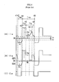
- Fig. 4 is a timing chart illustrating conventional AC pulse arc welding. Specifically, Graph 4(A) shows the waveform of a welding current Iw, Graph 4 (B) the waveform of a welding voltage Vw, and Graph 4 (C) the waveform of a polarity switching signal Cp.
- a polarity switching signal Cp changes from High level to Low level
- a switching operation from the electrode-positive polarity period Tep to the electrode-negative polarity period Ten is performed.
- the signal changes from Low level to High level
- a switching operation from the electrode-negative polarity period Ten to the electrode-positive polarity period Tep is performed.
- the polarity switching signal Cp assumes Low level at Time Point t1, whereupon the base current Ib of the electrode-positive polarity period Tep decreases, as shown in Graph 4(A), toward a predetermined polarity switching current value Ic.
- the welding current Iw becomes equal to the polarity switching current value Ic, whereupon a high voltage is applied, and as shown in Graph 4(B), the polarity is switched to the electrode-negative polarity period Ten.
- This period is an electrode-negative polarity EN.
- a predetermined electrode-negative current In is supplied, and an electrode-negative voltage Vn, as shown in Graph 4(B), is applied.
- the polarity switching signal Cp changes to assume High level, upon which the electrode-negative current In decreases toward the polarity switching current value Ic as shown in Graph 4(A).
- the welding current Iw becomes equal to the polarity switching current value Ic as shown in Graph 4(A), upon which a high voltage is applied and the polarity is switched to the electrode-positive polarity EP as shown in Graph 4(B).
- This period is a peak period Tp, in which the electrode-positive polarity EP is adopted.
- a predetermined peak current IP is supplied, and a peak voltage Vp, as shown in Graph 4(B), is applied.
- This period is a base period Tb determined by feed-back control. During this period, the electrode-positive polarity EP is adopted. As shown in Graph 4(A), a predetermined base current Ib is supplied, and a base voltage Vb, as shown in Graph 4(B), is applied.
- This period is included in the above-mentioned base period Tb.
- the welding voltage Vw assumes a low short-circuit voltage value, as shown in Graph 4(B).
- an increasing short-circuit current Is is applied to terminate the short-circuiting quickly and to generate the arc again.
- the arc recurs at Time Point t7. It should be noted that short-circuiting occurs not only in the base period Tb but also in the peak period Tp as well as in the electrode-negative polarity period Ten. For these occasions, the same operation of applying the short-circuit current Is is supplied.
- the period from Time Point t2 through Time Point t4 is an electrode-negative polarity period Ten
- the period from Time Point t4 through Time Point t9 is an electrode-positive polarity period Tep.
- the welding current Iw is decreased to the polarity switching current value Ic at the time of polarity switching.
- This is a conventionally common practice for protecting a polarity switching device from a surge voltage to be generated by polarity switching operation. For more information, see JP-A-H58-38664 and JP-A-2005-349406 , for example.
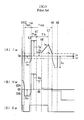
- Fig. 5 shows how waveforms change when short-circuiting occurs during polarity switching.
- the chart corresponds to Fig. 4 described above.
- processes from Time Point t1 through Time Point t6 are identical with thoese in Fig. 4 and so will not be described again. The process after Time Point t6 will be described.
- the welding current Iw becomes equal to the polarity switching current value Ic as shown in Fig. 5(A), whereupon the operational condition switches to electrode-negative polarity EN.
- the short-circuiting situation continues even after the polarity changes.
- the short-circuit current Is which has a large current value continues to be drawn at electrode-negative polarity EN even after Time Point t8, until Time Point t9, where the wire tip is melted and the arc ceases.
- the present invention has been provided in the above-described situation. It is therefore an object of the present invention to provide a polarity switching control method in consumable electrode AC pulse arc welding, which is capable of making stable polarity switching even if short-circuiting occurs at the time of polarity switching.
- a polarity switching control method in consumable electrode AC pulse arc welding comprises the steps of: applying a peak current and a base current during an electrode-positive polarity period; applying an electrode-negative current during an electrode-negative polarity period; and conducting polarity switching for the welding by alternating the electrode-positive polarity period and the electrode-negative polarity period.
- the present invention is advantageous for a case where the welding voltage is set at a low value for the purpose of reducing the heat conduction to the base metal or increasing the welding speed.
- the polarity switching may be performed after a lapse of a predetermined delay period starting from the generation of the arc. In this manner, it is possible to prevent short-circuiting from occurring immediately after the recurrence of the arc.
- a welding current applied at the generation of the arc may be maintained during the delay period. Since the welding current applied at the generation of the arc is high current, it is possible to attain a great arc length.
- Fig. 2 is a block diagram of a welding power source for implementing a polarity switching control method in consumable electrode AC pulse arc welding according to the present invention.
- An inverter circuit INV receives commercially available AC power such as three-phase 200 volts as an input, and performs the rectification and smoothing of the input. In addition, the inverter circuit INV performs an inverter control in accordance with a pulse width modulation signal Pwm to be described later, and outputs high-frequency alternating current.
- a high-frequency transformer INT decreases the high-frequency AC to a voltage suitable to arc welding.
- Secondary rectifiers D2a through D2d rectify the reduced high-frequency AC.
- a reactor WL smoothes the rectified DC output.
- Transistors TR1 through TR4 constitute a secondary inverter circuit which outputs a welding voltage Vw and a welding current Iw in the electrode-positive polarity EP or in the electrode-negative polarity EN.
- the electrode-positive polarity EP is attained when the transistors TR1 and TR2 are turned on, while the electrode-negative polarity EN is attained when the transistors TR3 and TR4 are turned on.
- a welding wire 1 is fed by feed rollers 5 of a wire feeder, through a welding torch 4 so as to generate an arc 3 between itself and a base metal 2.
- a voltage detection circuit VD detects the welding voltage Vw and outputs a voltage detection signal Vd.
- An average voltage calculation circuit VAV averages the voltage detection signals Vd, and outputs an average voltage signal Vav.
- a voltage setting circuit VR outputs a predetermined voltage setting signal Vr.
- a voltage error amplification circuit EV amplifies an error between the voltage setting signal Vr and the average voltage signal Vav, and outputs a voltage error amplification signal ⁇ V.
- a V/F converter circuit VF outputs a pulse period signal Tf of a frequency proportional to the voltage error amplification signal ⁇ V. With this arrangement, the pulse period (base period) is subjected to a feedback control so that the average of the welding voltage Vw becomes equal to the value of voltage setting signal Vr.
- a current detection circuit ID detects the welding current Iw, calculates the absolute value thereof, and outputs a current detection signal Id.
- a short-circuit determination circuit SD checks the value of the voltage detection signal Vd to see if there is a short circuit situation, and outputs a short-circuit identification signal Sd.
- An electric-current comparison circuit CM outputs an electric-current comparison signal Cm which assumes High level when the current detection signal Id is no greater than a predetermined polarity switching current value Ic.
- a main control circuit CC receives the pulse period signal Tf, the short-circuit identification signal Sd and the electric-current comparison signal Cm as inputs, performs an operation which will be described later with reference to Fig. 1, and then outputs an operation-stop signal St, an electric-current setting signal Ir and an operation control signal Dc.
- An electric-current error amplification circuit EI amplifies an error between the electric-current setting signal Ir and the current detection signal Id, and outputs an electric-current error amplification signal Ei.
- a pulse width modulation circuit PWM performs pulse width modulation based on the electric-current error amplification signal Ei when there is no output of the operation-stop signal St (when the signal assumes Low level), and outputs a pulse width modulation signal Pwm.
- a drive circuit DV drives the transistors TR1 through TR4 based on the operation control signal Dc.
- Fig. 1 shows a polarity switching control method in consumable electrode AC pulse arc welding according to the present invention.
- the figure is a timing chart which shows some of the signals in the above-described welding power source.
- Graph 1(A) shows the welding current Iw
- Graph 1(B) shows the welding voltage Vw
- Graph 1(C) shows the pulse period signal Tf
- Graph 1(D) shows the operation-stop signal St
- Graph 1(E) shows the operation control signal Dc.
- Fig. 1 shows an instance where there is short-circuiting at the time of polarity switching.
- the pulse period signal Tf assumes High level for a short period of time at Time Point t1, whereupon the operation-stop signal St assumes High level as shown in Graph 1(D), causing the welding power source to stop its output, and the welding current Iw decreases, as shown in Graph 1(A).
- the welding current Iw decreases to a polarity switching current value Ic, whereupon the electric-current comparison signal Cm in Fig. 2 changes to High level and the operation-stop signal St returns to Low level as shown in Graph 1(D), causing the welding power source to start its output.
- the electric-current setting signal Ir in Fig. 2 assumes a value equal to the electrode-negative current In
- the operation control signal Dc changes to Low level, causing the transistors TR3 and TR4 to be turned on to switch to electrode-negative polarity EN.
- the operation control signal Dc stays at Low level as shown in Graph 1(E), and thus the electrode-negative current In is supplied as shown in Graph 1(A) and an electrode-negative voltage as shown in Graph 1(B) is applied.
- the operation-stop signal St assumes High level as shown in Graph 1(D), causing the welding power source to stop its output, and the welding current Iw decreases as shown in Graph 1(A).
- the welding current Iw decreases to the polarity switching current value Ic, whereupon the electric-current comparison signal Cm in Fig. 2 changes to High level, and the operation-stop signal St returns to Low level as shown in Graph 1(D), causing the welding power source to start its output.
- the electric-current setting signal Ir in Fig. 2 assumes a value equal to the peak current Ip, and as shown in Graph 1(E), the operation control signal Dc changes to High level, causing the transistors TR1 and TR2 to be turned on to switch to the electrode-positive polarity EP.
- the operation control signal Dc remains at High level as shown in Graph 1(E).
- a peak current Ip is supplied as shown in Graph 1(A) in electrode-positive polarity EP, and a peak voltage as shown in Graph 1(B) is applied.
- a base current Ib is supplied as shown in Graph 1(A), and a base voltage as shown in Graph 1(B) is applied.
- the welding voltage Vw assumes a low short-circuit voltage value as shown in Graph 1(B) whereas as shown in Graph 1(A), the welding current Iw assumes a short-circuit current Is and increases.
- the pulse period signal Tf changes to High level as shown in Graph 1(C) for a short period of time.
- the polarity switching operation is not performed because there is short-circuiting.
- the operation-stop signal St remains unchanged.
- the short-circuit current Is continues to be supplied as shown in Graph 1(A).
- the arc resumes due to the application of the short-circuit current Is.
- the current value at the time of arc recurrence is maintained.
- the current value may be brought back to the base current value Ib.
- the delay period Td is provided for the purpose of preventing short-circuiting from recurring immediately after the generation of the arc.
- the duration of delay period Td is selected appropriately within a range from zero through a few milliseconds. There may be a case where no delay period is necessary.
- the operation-stop signal St assumes High level as shown in Graph 1(D), causing the welding power source to stop its output, and as shown in Graph 1(A), the welding current Iw decreases.
- the welding current Iw becomes as low as the polarity switching current value Ic whereupon the electric-current comparison signal Cm in Fig. 2 changes to High level, the operation-stop signal St returns to Low level as shown in Graph 1(D), causing the welding power source to start its output.
- the electric-current setting signal Ir in Fig. 2 assumes a value equal to the electrode-negative current In, and as shown in Graph 1(E), the operation control signal Dc changes to Low level, causing the transistors TR3 and TR4 to be turned on to switch to the electrode-negative polarity EN.
- the welding is performed by repeating the cycle of the above-described processes (1) through (9).
- a polarity switching operation is performed after the arc resumes when short-circuiting is present at the time of polarity switching. This stabilizes the polarity switching, and serves to prevent prolonged short-circuiting and arc interruption.
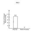
- Fig. 3 is a comparative figure illustrating the advantage of the present invention in terms of the number of occurrences of prolonged short-circuiting events.
- the comparative study was made in AC pulse MIG welding at 100A and 15. 5V, using an aluminum alloy wire having a diameter of 1.2 mm, and occurrences of a prolonged short-circuiting which lasted for a period not shorter than 10 ms were counted during a period of 30 seconds. It should be noted that in the comparative study, the welding voltage was set to a low value within an appropriate range, in order to create a favorable condition for the occurrence of short-circuiting.
Landscapes
- Engineering & Computer Science (AREA)
- Physics & Mathematics (AREA)
- Plasma & Fusion (AREA)
- Mechanical Engineering (AREA)
- Arc Welding Control (AREA)
Abstract
Description
- The present invention relates to a polarity switching control method for improving stability during polarity switching in consumable electrode AC pulse arc welding.
- For consumable electrode AC pulse arc welding (referred to as "AC pulse arc welding" below), a welding wire is supplied at constant speed, and two periods, i.e. an electrode-positive polarity period Tep and an electrode-negative polarity period Ten, are caused to alternate with each other. During the electrode-positive polarity period Tep, peak current Ip and base current Ib are applied, whereas during the electrode-negative polarity period Ten, electrode-negative current In is applied. In order to achieve high quality welding, it is important in AC pulse arc welding that polarity switching is performed properly so that no arc interruption occurs. To this end, conventionally, a high voltage is applied between the welding wire and the base metal in switching the polarity, as described below.
- Fig. 4 is a timing chart illustrating conventional AC pulse arc welding. Specifically, Graph 4(A) shows the waveform of a welding current Iw, Graph 4 (B) the waveform of a welding voltage Vw, and Graph 4 (C) the waveform of a polarity switching signal Cp. When the polarity switching signal Cp changes from High level to Low level, a switching operation from the electrode-positive polarity period Tep to the electrode-negative polarity period Ten is performed. When the signal changes from Low level to High level, a switching operation from the electrode-negative polarity period Ten to the electrode-positive polarity period Tep is performed. A more specific explanation is given below.
- As shown in Graph 4(C), the polarity switching signal Cp assumes Low level at Time Point t1, whereupon the base current Ib of the electrode-positive polarity period Tep decreases, as shown in Graph 4(A), toward a predetermined polarity switching current value Ic. At Time Point t2, the welding current Iw becomes equal to the polarity switching current value Ic, whereupon a high voltage is applied, and as shown in Graph 4(B), the polarity is switched to the electrode-negative polarity period Ten.
- This period is an electrode-negative polarity EN. As shown in Graph 4(A), a predetermined electrode-negative current In is supplied, and an electrode-negative voltage Vn, as shown in Graph 4(B), is applied.
- At Time Point t3, as shown in Graph 4(C), the polarity switching signal Cp changes to assume High level, upon which the electrode-negative current In decreases toward the polarity switching current value Ic as shown in Graph 4(A). At Time Point t4, the welding current Iw becomes equal to the polarity switching current value Ic as shown in Graph 4(A), upon which a high voltage is applied and the polarity is switched to the electrode-positive polarity EP as shown in Graph 4(B).
- This period is a peak period Tp, in which the electrode-positive polarity EP is adopted. As shown in Graph 4(A) a predetermined peak current IP is supplied, and a peak voltage Vp, as shown in Graph 4(B), is applied.
- This period is a base period Tb determined by feed-back control. During this period, the electrode-positive polarity EP is adopted. As shown in Graph 4(A), a predetermined base current Ib is supplied, and a base voltage Vb, as shown in Graph 4(B), is applied.
- In this period, the process goes back to the (1) operation described above.
- This period is included in the above-mentioned base period Tb. When short-circuiting occurs between the welding wire and the base metal, the welding voltage Vw assumes a low short-circuit voltage value, as shown in Graph 4(B). At the same time, as shown in Graph 4(A), an increasing short-circuit current Is is applied to terminate the short-circuiting quickly and to generate the arc again. As a result, the arc recurs at Time Point t7. It should be noted that short-circuiting occurs not only in the base period Tb but also in the peak period Tp as well as in the electrode-negative polarity period Ten. For these occasions, the same operation of applying the short-circuit current Is is supplied.
- As seen from Fig. 4, the period from Time Point t2 through Time Point t4 is an electrode-negative polarity period Ten, and the period from Time Point t4 through Time Point t9 is an electrode-positive polarity period Tep. As described, the welding current Iw is decreased to the polarity switching current value Ic at the time of polarity switching. This is a conventionally common practice for protecting a polarity switching device from a surge voltage to be generated by polarity switching operation. For more information, see
JP-A-H58-38664 JP-A-2005-349406 - In the above conventional AC pulse arc welding, stable polarity switching is achieved by applying a high voltage at the time of polarity switching, thereby preventing arc interruption. However, if short-circuiting occurs during the polarity switching, there is a high likelihood for occurrence of prolonged short-circuiting and arc interruption. This problem is descried below with reference to Fig. 5.
- Fig. 5 shows how waveforms change when short-circuiting occurs during polarity switching. The chart corresponds to Fig. 4 described above. In Fig. 5, processes from Time Point t1 through Time Point t6 are identical with thoese in Fig. 4 and so will not be described again. The process after Time Point t6 will be described.
- When short-circuiting occurs at Time Point t6, the welding voltage Vw assumes a low short-circuit voltage value as shown in Fig. 5(B) whereas the welding current Iw assumes the short-circuit current Is, i.e. increases as shown in Fig. 5(A). At Time Point t7, the polarity switching signal Cp changes to assume Low level as shown in Fig. 5(C), the operation begins to shift to the electrode-negative polarity EN, and therefore, the welding current Iw (short-circuit current Is) decreases as shown in Fig. 5(A) toward the polarity switching current value Ic. However, as shown in Fig. 5(B), because of the short circuit situation, the decrease in the welding current Iw is substantially slower as shown in Fig. 5(A) than the decrease under an arcing situation. Since the welding current Iw is decreased in spite of the short-circuiting situation, the short-circuiting becomes less likely to be terminated during the period from Time Point t7 to Time Point t8.
- At Time Point t8, the welding current Iw becomes equal to the polarity switching current value Ic as shown in Fig. 5(A), whereupon the operational condition switches to electrode-negative polarity EN. However, as shown in Fig. 5(B), the short-circuiting situation continues even after the polarity changes. Thus, as shown in Fig. 5(A), the short-circuit current Is which has a large current value continues to be drawn at electrode-negative polarity EN even after Time Point t8, until Time Point t9, where the wire tip is melted and the arc ceases.
- When short-circuiting occurs during polarity switching, the decreasing of the welding current Iw causes the short-circuiting to persist, thereby making the arc unstable or even broken by melting. Behind such a phenomenon is a fact that the pulse arc welding is not a short-circuit transfer welding. In pulse arc welding, it is necessary to quickly terminate short-circuiting and regenerate the arc for stable arcing. In short-circuit transfer welding such as CO2 welding or MAG welding, short-circuiting occurs periodically about 100 times per second, so polarity switching can be performed successfully during the short-circuiting period. In pulse arc welding, however, short-circuiting occurs irregularly. In light of this, the polarity switching is to be performed while the arc is being generated.
- The present invention has been provided in the above-described situation. It is therefore an object of the present invention to provide a polarity switching control method in consumable electrode AC pulse arc welding, which is capable of making stable polarity switching even if short-circuiting occurs at the time of polarity switching.
- According to the present invention, there is provided a polarity switching control method in consumable electrode AC pulse arc welding. The method comprises the steps of: applying a peak current and a base current during an electrode-positive polarity period; applying an electrode-negative current during an electrode-negative polarity period; and conducting polarity switching for the welding by alternating the electrode-positive polarity period and the electrode-negative polarity period. When a consumable electrode and a base metal are in short circuit with each other, the polarity switching is performed after the short circuit is broken and an arc is generated.
- With the above arrangement, the polarity switching is not performed while short-circuiting is present, but performed after the short-circuiting comes to an end and the arc is generated. Accordingly, it is possible to perform stable polarity switching and prevent prolonged short-circuiting or arc interruption. In particular, the present invention is advantageous for a case where the welding voltage is set at a low value for the purpose of reducing the heat conduction to the base metal or increasing the welding speed.
- Preferably, the polarity switching may be performed after a lapse of a predetermined delay period starting from the generation of the arc. In this manner, it is possible to prevent short-circuiting from occurring immediately after the recurrence of the arc.
- Preferably, a welding current applied at the generation of the arc may be maintained during the delay period. Since the welding current applied at the generation of the arc is high current, it is possible to attain a great arc length.
-
- Fig. 1 is a timing chart which shows a polarity switching control method in consumable electrode AC pulse arc welding according to the present invention.
- Fig. 2 is a block diagram of a welding power source used for implementing the method of the present invention.
- Fig. 3 shows the number of occurrences of prolonged short-circuiting as a comparison between the prior art and the present invention.
- Fig. 4 is an electric-current/voltage waveform chart in a conventional AC pulse arc welding.
- Fig. 5 is an electric-current/voltage waveform chart corresponding to Fig. 4.
- Preferred embodiments of the present invention will be described below with reference to the accompanying drawings.
- Fig. 2 is a block diagram of a welding power source for implementing a polarity switching control method in consumable electrode AC pulse arc welding according to the present invention.
- An inverter circuit INV receives commercially available AC power such as three-phase 200 volts as an input, and performs the rectification and smoothing of the input. In addition, the inverter circuit INV performs an inverter control in accordance with a pulse width modulation signal Pwm to be described later, and outputs high-frequency alternating current. A high-frequency transformer INT decreases the high-frequency AC to a voltage suitable to arc welding. Secondary rectifiers D2a through D2d rectify the reduced high-frequency AC. A reactor WL smoothes the rectified DC output. Transistors TR1 through TR4 constitute a secondary inverter circuit which outputs a welding voltage Vw and a welding current Iw in the electrode-positive polarity EP or in the electrode-negative polarity EN. The electrode-positive polarity EP is attained when the transistors TR1 and TR2 are turned on, while the electrode-negative polarity EN is attained when the transistors TR3 and TR4 are turned on. A
welding wire 1 is fed byfeed rollers 5 of a wire feeder, through awelding torch 4 so as to generate anarc 3 between itself and abase metal 2. - A voltage detection circuit VD detects the welding voltage Vw and outputs a voltage detection signal Vd. An average voltage calculation circuit VAV averages the voltage detection signals Vd, and outputs an average voltage signal Vav. A voltage setting circuit VR outputs a predetermined voltage setting signal Vr. A voltage error amplification circuit EV amplifies an error between the voltage setting signal Vr and the average voltage signal Vav, and outputs a voltage error amplification signal ΔV. A V/F converter circuit VF outputs a pulse period signal Tf of a frequency proportional to the voltage error amplification signal ΔV. With this arrangement, the pulse period (base period) is subjected to a feedback control so that the average of the welding voltage Vw becomes equal to the value of voltage setting signal Vr.
- A current detection circuit ID detects the welding current Iw, calculates the absolute value thereof, and outputs a current detection signal Id. A short-circuit determination circuit SD checks the value of the voltage detection signal Vd to see if there is a short circuit situation, and outputs a short-circuit identification signal Sd. An electric-current comparison circuit CM outputs an electric-current comparison signal Cm which assumes High level when the current detection signal Id is no greater than a predetermined polarity switching current value Ic. A main control circuit CC receives the pulse period signal Tf, the short-circuit identification signal Sd and the electric-current comparison signal Cm as inputs, performs an operation which will be described later with reference to Fig. 1, and then outputs an operation-stop signal St, an electric-current setting signal Ir and an operation control signal Dc.
- An electric-current error amplification circuit EI amplifies an error between the electric-current setting signal Ir and the current detection signal Id, and outputs an electric-current error amplification signal Ei. A pulse width modulation circuit PWM performs pulse width modulation based on the electric-current error amplification signal Ei when there is no output of the operation-stop signal St (when the signal assumes Low level), and outputs a pulse width modulation signal Pwm. A drive circuit DV drives the transistors TR1 through TR4 based on the operation control signal Dc.
- Fig. 1 shows a polarity switching control method in consumable electrode AC pulse arc welding according to the present invention. The figure is a timing chart which shows some of the signals in the above-described welding power source. Graph 1(A) shows the welding current Iw, Graph 1(B) shows the welding voltage Vw, Graph 1(C) shows the pulse period signal Tf, Graph 1(D) shows the operation-stop signal St, and Graph 1(E) shows the operation control signal Dc. Fig. 1 shows an instance where there is short-circuiting at the time of polarity switching.
- As shown in Graph 1(C), the pulse period signal Tf assumes High level for a short period of time at Time Point t1, whereupon the operation-stop signal St assumes High level as shown in Graph 1(D), causing the welding power source to stop its output, and the welding current Iw decreases, as shown in Graph 1(A). At Time Point t2, the welding current Iw decreases to a polarity switching current value Ic, whereupon the electric-current comparison signal Cm in Fig. 2 changes to High level and the operation-stop signal St returns to Low level as shown in Graph 1(D), causing the welding power source to start its output. In response to this, the electric-current setting signal Ir in Fig. 2 assumes a value equal to the electrode-negative current In, and as shown in Graph 1(E), the operation control signal Dc changes to Low level, causing the transistors TR3 and TR4 to be turned on to switch to electrode-negative polarity EN.
- In this period, the operation control signal Dc stays at Low level as shown in Graph 1(E), and thus the electrode-negative current In is supplied as shown in Graph 1(A) and an electrode-negative voltage as shown in Graph 1(B) is applied.
- Upon a lapse of a predetermined time, i.e. at Time Point t4, the operation-stop signal St assumes High level as shown in Graph 1(D), causing the welding power source to stop its output, and the welding current Iw decreases as shown in Graph 1(A). At Time Point t4, the welding current Iw decreases to the polarity switching current value Ic, whereupon the electric-current comparison signal Cm in Fig. 2 changes to High level, and the operation-stop signal St returns to Low level as shown in Graph 1(D), causing the welding power source to start its output. In response to this, the electric-current setting signal Ir in Fig. 2 assumes a value equal to the peak current Ip, and as shown in Graph 1(E), the operation control signal Dc changes to High level, causing the transistors TR1 and TR2 to be turned on to switch to the electrode-positive polarity EP.
- In this peak period Tp, the operation control signal Dc remains at High level as shown in Graph 1(E). Thus, a peak current Ip is supplied as shown in Graph 1(A) in electrode-positive polarity EP, and a peak voltage as shown in Graph 1(B) is applied.
- In this period included in the base period Tb, a base current Ib is supplied as shown in Graph 1(A), and a base voltage as shown in Graph 1(B) is applied.
- When short-circuiting occurs at Time Point t6, the welding voltage Vw assumes a low short-circuit voltage value as shown in Graph 1(B) whereas as shown in Graph 1(A), the welding current Iw assumes a short-circuit current Is and increases.
- At Time Point t7, the pulse period signal Tf changes to High level as shown in Graph 1(C) for a short period of time. However, the polarity switching operation is not performed because there is short-circuiting. As shown in Graph 1(D), the operation-stop signal St remains unchanged. Thus, the short-circuit current Is continues to be supplied as shown in Graph 1(A).
- At Time Point t8, the arc resumes due to the application of the short-circuit current Is. In a predetermined delay period starting from Time Point t8 to Time point t9, the current value at the time of arc recurrence is maintained. Alternatively, during this period, the current value may be brought back to the base current value Ib. The delay period Td is provided for the purpose of preventing short-circuiting from recurring immediately after the generation of the arc. The duration of delay period Td is selected appropriately within a range from zero through a few milliseconds. There may be a case where no delay period is necessary.
- When the delay period Td expires at Time Point t9, the operation-stop signal St assumes High level as shown in Graph 1(D), causing the welding power source to stop its output, and as shown in Graph 1(A), the welding current Iw decreases. At Time Point t10, the welding current Iw becomes as low as the polarity switching current value Ic whereupon the electric-current comparison signal Cm in Fig. 2 changes to High level, the operation-stop signal St returns to Low level as shown in Graph 1(D), causing the welding power source to start its output. In response to this, the electric-current setting signal Ir in Fig. 2 assumes a value equal to the electrode-negative current In, and as shown in Graph 1(E), the operation control signal Dc changes to Low level, causing the transistors TR3 and TR4 to be turned on to switch to the electrode-negative polarity EN.
- The welding is performed by repeating the cycle of the above-described processes (1) through (9). According to the above-described embodiment, a polarity switching operation is performed after the arc resumes when short-circuiting is present at the time of polarity switching. This stabilizes the polarity switching, and serves to prevent prolonged short-circuiting and arc interruption.
- Fig. 3 is a comparative figure illustrating the advantage of the present invention in terms of the number of occurrences of prolonged short-circuiting events. The comparative study was made in AC pulse MIG welding at 100A and 15. 5V, using an aluminum alloy wire having a diameter of 1.2 mm, and occurrences of a prolonged short-circuiting which lasted for a period not shorter than 10 ms were counted during a period of 30 seconds. It should be noted that in the comparative study, the welding voltage was set to a low value within an appropriate range, in order to create a favorable condition for the occurrence of short-circuiting.
- As shown in the figure, 83 short-circuiting events resulted in prolonged short circuit when the conventional technique was used. On the contrary, the count was zero with the present invention. In both cases total numbers of the short-circuiting events were substantially the same, which indicates that the present invention prevents prolonged short-circuiting and promotes arc recurrence. Absence of prolonged short-circuiting means no arc interruption and hence improved arc stability.
Claims (3)
- A polarity switching control method in consumable electrode AC pulse arc welding, the method comprising the steps of:applying a peak current and a base current during an electrode-positive polarity period;applying an electrode-negative current during an electrode-negative polarity period; andconducting polarity switching for the welding by alternating the electrode-positive polarity period and the electrode-negative polarity period;wherein when a consumable electrode and a base metal are in short circuit with each other, the polarity switching is performed after the short circuit is broken and an arc is generated.
- The method according to claim 1, wherein the polarity switching is performed after a lapse of a predetermined delay period starting from the generation of the arc.
- The method according to claim 2, wherein a welding current applied at the generation of the arc is maintained during the delay period.
Applications Claiming Priority (1)
| Application Number | Priority Date | Filing Date | Title |
|---|---|---|---|
| JP2006116930A JP4916759B2 (en) | 2006-04-20 | 2006-04-20 | Polarity switching control method for consumable electrode AC pulse arc welding |
Publications (3)
| Publication Number | Publication Date |
|---|---|
| EP1847348A2 true EP1847348A2 (en) | 2007-10-24 |
| EP1847348A3 EP1847348A3 (en) | 2008-01-02 |
| EP1847348B1 EP1847348B1 (en) | 2017-01-25 |
Family
ID=38255326
Family Applications (1)
| Application Number | Title | Priority Date | Filing Date |
|---|---|---|---|
| EP07251243.7A Ceased EP1847348B1 (en) | 2006-04-20 | 2007-03-23 | Polarity switching method in consumable electrode AC pulse arc welding |
Country Status (4)
| Country | Link |
|---|---|
| US (1) | US8592720B2 (en) |
| EP (1) | EP1847348B1 (en) |
| JP (1) | JP4916759B2 (en) |
| CN (1) | CN101058124B (en) |
Cited By (1)
| Publication number | Priority date | Publication date | Assignee | Title |
|---|---|---|---|---|
| WO2015150899A3 (en) * | 2014-04-04 | 2016-01-21 | Lincoln Global, Inc. | Method and system to use ac welding waveform and enhanced consumable to improve welding of galvanized workpiece |
Families Citing this family (26)
| Publication number | Priority date | Publication date | Assignee | Title |
|---|---|---|---|---|
| ATE513647T1 (en) * | 2007-02-13 | 2011-07-15 | Pangas | METHOD FOR ARC JOINING USING ALTERNATING CURRENT |
| US9895760B2 (en) * | 2007-09-26 | 2018-02-20 | Lincoln Global, Inc. | Method and system to increase heat input to a weld during a short-circuit arc welding process |
| DE102008024977A1 (en) * | 2008-05-23 | 2009-11-26 | Linde Ag | Method of arc joining |
| JP2010075944A (en) * | 2008-09-25 | 2010-04-08 | Daihen Corp | Ac arc welding machine |
| JP5557238B2 (en) | 2008-12-24 | 2014-07-23 | 株式会社ダイヘン | AC pulse arc welding control method |
| CN102056699B (en) * | 2009-01-28 | 2013-10-09 | 松下电器产业株式会社 | AC pulse arc welding method |
| JP5766406B2 (en) * | 2010-04-19 | 2015-08-19 | 株式会社神戸製鋼所 | Consumable electrode arc welding method |
| JP5429362B2 (en) * | 2010-09-01 | 2014-02-26 | パナソニック株式会社 | AC TIG welding method |
| US9162308B2 (en) * | 2010-10-22 | 2015-10-20 | Lincoln Global, Inc. | Apparatus and method for pulse welding with AC waveform |
| US9415457B2 (en) | 2010-10-22 | 2016-08-16 | Lincoln Global, Inc. | Method to control an arc welding system to reduce spatter |
| WO2012164833A1 (en) * | 2011-06-03 | 2012-12-06 | パナソニック株式会社 | Arc welding control method and arc welding device |
| US9533366B2 (en) * | 2013-03-14 | 2017-01-03 | Lincoln Global, Inc. | Apparatus and method for welding with AC waveform |
| KR102199238B1 (en) * | 2014-02-24 | 2021-01-06 | 가부시키가이샤 다이헨 | Arc welding method |
| CN104057177B (en) * | 2014-07-09 | 2016-01-20 | 上海威特力焊接设备制造股份有限公司 | A kind of control circuit for short circuiting arc welding |
| JP6395644B2 (en) * | 2015-02-27 | 2018-09-26 | 株式会社神戸製鋼所 | Arc welding method, arc welding apparatus and arc welding control apparatus |
| US11090752B2 (en) * | 2016-02-04 | 2021-08-17 | Panasonic Intellectual Property Management Co., Ltd. | Pulsed arc welding control method and pulsed arc welding device |
| US10974341B2 (en) * | 2016-06-28 | 2021-04-13 | Lincoln Global, Inc. | Welding waveform for stainless steel applications |
| US9833860B1 (en) * | 2016-07-22 | 2017-12-05 | Lincoln Global, Inc. | System and method for plasma arc transfer for plasma cutting |
| US12005530B2 (en) * | 2016-10-24 | 2024-06-11 | Daihen Corporation | AC pulse arc welding control method |
| US11110536B2 (en) * | 2017-01-27 | 2021-09-07 | Lincoln Global, Inc. | Apparatus and method for welding with AC waveform |
| JP7106799B2 (en) * | 2018-06-15 | 2022-07-27 | 株式会社ダイヘン | welding power supply |
| US12115604B2 (en) * | 2018-10-19 | 2024-10-15 | Illinois Tool Works Inc. | Systems and methods for voltage control of a short circuit during a pulse welding process |
| US12128508B2 (en) * | 2018-10-22 | 2024-10-29 | Illinois Tool Works Inc. | Systems and methods for controlling arc initiation and termination in a welding process |
| JP7188858B2 (en) * | 2019-02-13 | 2022-12-13 | 株式会社ダイヘン | arc welding method |
| JPWO2023095623A1 (en) * | 2021-11-29 | 2023-06-01 | ||
| JP7690412B2 (en) * | 2022-02-10 | 2025-06-10 | 株式会社ダイヘン | Arc welding control method |
Family Cites Families (18)
| Publication number | Priority date | Publication date | Assignee | Title |
|---|---|---|---|---|
| JPS5781959A (en) * | 1980-11-10 | 1982-05-22 | Mitsubishi Electric Corp | Pulse arc welding device |
| JPS5838664A (en) | 1981-08-31 | 1983-03-07 | Mitsubishi Electric Corp | Consumable electrode type arc welding machine |
| US4553018A (en) * | 1983-10-27 | 1985-11-12 | Mitsubishi Denki Kabushiki Kaisha | Short circuiting transfer arc welding machine |
| JPH01133679A (en) * | 1987-11-18 | 1989-05-25 | Kobe Steel Ltd | Method for controlling output of power source for consumable electrode ac arc welding |
| KR910004997B1 (en) * | 1987-05-12 | 1991-07-20 | 가부시끼가이샤 고오베 세이꼬오쇼 | Arc welding power supply system |
| JP2819607B2 (en) | 1989-04-29 | 1998-10-30 | 株式会社ダイヘン | MIG and MAG pulse arc welding method |
| DE4023155C2 (en) * | 1989-07-21 | 1997-02-06 | Hitachi Seiko Kk | AC inert gas arc welding process and consumable electrode device |
| JP3317946B2 (en) * | 1992-08-17 | 2002-08-26 | 松下電器産業株式会社 | Consumable electrode AC arc welding machine |
| JPH06170542A (en) * | 1992-12-04 | 1994-06-21 | Toshiba Corp | Inert gas arc welding equipment |
| JP3867415B2 (en) * | 1997-09-20 | 2007-01-10 | 松下電器産業株式会社 | Polarity switching control method and consumable electrode arc welding power source |
| JP4846898B2 (en) * | 2000-09-12 | 2011-12-28 | 株式会社ダイヘン | AC pulse arc welding control method and welding power source apparatus |
| US7102099B2 (en) * | 2002-07-23 | 2006-09-05 | Illinois Tool Works Inc. | Method and apparatus for feeding wire to a welding arc |
| JP4739641B2 (en) * | 2002-09-26 | 2011-08-03 | 株式会社ダイヘン | Power supply device for short-circuit arc welding and robot welding device |
| JP4181384B2 (en) * | 2002-11-13 | 2008-11-12 | 株式会社ダイヘン | Welding current control method for pulse arc welding |
| US7105772B2 (en) * | 2003-03-24 | 2006-09-12 | Lincoln Global, Inc. | Arc welding system and method |
| JP2005349406A (en) * | 2004-06-08 | 2005-12-22 | Daihen Corp | Method for discriminating short circuit of ac pulsed arc welding |
| JP4459768B2 (en) * | 2004-09-22 | 2010-04-28 | 株式会社ダイヘン | AC pulse arc welding welding current control method |
| US7968822B2 (en) * | 2005-03-28 | 2011-06-28 | Lincoln Global, Inc. | Arc welding system |
-
2006
- 2006-04-20 JP JP2006116930A patent/JP4916759B2/en not_active Expired - Lifetime
-
2007
- 2007-03-02 CN CN2007100850966A patent/CN101058124B/en not_active Expired - Fee Related
- 2007-03-06 US US11/714,901 patent/US8592720B2/en not_active Expired - Fee Related
- 2007-03-23 EP EP07251243.7A patent/EP1847348B1/en not_active Ceased
Cited By (5)
| Publication number | Priority date | Publication date | Assignee | Title |
|---|---|---|---|---|
| WO2015150899A3 (en) * | 2014-04-04 | 2016-01-21 | Lincoln Global, Inc. | Method and system to use ac welding waveform and enhanced consumable to improve welding of galvanized workpiece |
| KR20160140852A (en) * | 2014-04-04 | 2016-12-07 | 링컨 글로벌, 인크. | Method and system to use ac welding waveform and enhanced consumable to improve welding of galvanized workpiece |
| US10052707B2 (en) | 2014-04-04 | 2018-08-21 | Lincoln Global, Inc. | Method and system to use AC welding waveform and enhanced consumable to improve welding of galvanized workpiece |
| US10052706B2 (en) | 2014-04-04 | 2018-08-21 | Lincoln Global, Inc. | Method and system to use AC welding waveform and enhanced consumable to improve welding of galvanized workpiece |
| EP3299107A3 (en) * | 2014-04-04 | 2018-08-29 | Lincoln Global, Inc. | Method and system to use ac welding waveform and enhanced consumable to improve welding of galvanized workpiece |
Also Published As
| Publication number | Publication date |
|---|---|
| JP2007283393A (en) | 2007-11-01 |
| US8592720B2 (en) | 2013-11-26 |
| CN101058124A (en) | 2007-10-24 |
| JP4916759B2 (en) | 2012-04-18 |
| EP1847348A3 (en) | 2008-01-02 |
| CN101058124B (en) | 2013-05-22 |
| US20070246448A1 (en) | 2007-10-25 |
| EP1847348B1 (en) | 2017-01-25 |
Similar Documents
| Publication | Publication Date | Title |
|---|---|---|
| EP1847348B1 (en) | Polarity switching method in consumable electrode AC pulse arc welding | |
| CN104722885B (en) | Arc welding method and arc welding apparatus | |
| US7800016B2 (en) | Polarity switching short circuiting arc welding method | |
| US8049140B2 (en) | Pulse arc welding control method and pulse arc welding device | |
| CN101444868B (en) | Neckdown detection control method for arc welding of consumable electrode | |
| EP1681123A2 (en) | Arc start control method for AC arc welding | |
| WO2006006350A1 (en) | Arc welding control method and arc welding device | |
| JP2000000669A (en) | Pulse output control method and consumable electrode type pulse arc welding apparatus | |
| JP7678649B2 (en) | Arc welding method | |
| US11491571B2 (en) | Arc welding method | |
| JP4643113B2 (en) | Welding method and power supply device for welding | |
| JP3110295B2 (en) | Control method of consumable electrode type AC arc welding machine | |
| JP7576764B2 (en) | DC arc welding control method | |
| JP7677920B2 (en) | Arc welding method | |
| JP4661164B2 (en) | Consumable electrode arc welding equipment | |
| JP2023040450A (en) | arc welding method | |
| JP2022185999A (en) | Arc-welding device | |
| JP2005349406A (en) | Method for discriminating short circuit of ac pulsed arc welding | |
| EP4227033B1 (en) | Arc welding control method | |
| JP2024021966A (en) | How to deal with magnetic blowing during pulsed arc welding | |
| JP2025068841A (en) | Method for starting non-consumable electrode arc welding | |
| JP2023183971A (en) | Polarity control method for pulsed arc welding | |
| JP2024099107A (en) | Arc welding control method | |
| JP2024056415A (en) | Method for controlling constriction detection | |
| JP2024161638A (en) | Pulse arc welding control method |
Legal Events
| Date | Code | Title | Description |
|---|---|---|---|
| PUAI | Public reference made under article 153(3) epc to a published international application that has entered the european phase |
Free format text: ORIGINAL CODE: 0009012 |
|
| AK | Designated contracting states |
Kind code of ref document: A2 Designated state(s): AT BE BG CH CY CZ DE DK EE ES FI FR GB GR HU IE IS IT LI LT LU LV MC MT NL PL PT RO SE SI SK TR |
|
| AX | Request for extension of the european patent |
Extension state: AL BA HR MK YU |
|
| PUAL | Search report despatched |
Free format text: ORIGINAL CODE: 0009013 |
|
| AK | Designated contracting states |
Kind code of ref document: A3 Designated state(s): AT BE BG CH CY CZ DE DK EE ES FI FR GB GR HU IE IS IT LI LT LU LV MC MT NL PL PT RO SE SI SK TR |
|
| AX | Request for extension of the european patent |
Extension state: AL BA HR MK YU |
|
| RIC1 | Information provided on ipc code assigned before grant |
Ipc: B23K 9/09 20060101AFI20071127BHEP Ipc: B23H 1/00 20060101ALI20071127BHEP |
|
| 17P | Request for examination filed |
Effective date: 20080208 |
|
| 17Q | First examination report despatched |
Effective date: 20080320 |
|
| AKX | Designation fees paid |
Designated state(s): DE GB |
|
| GRAP | Despatch of communication of intention to grant a patent |
Free format text: ORIGINAL CODE: EPIDOSNIGR1 |
|
| INTG | Intention to grant announced |
Effective date: 20160825 |
|
| GRAS | Grant fee paid |
Free format text: ORIGINAL CODE: EPIDOSNIGR3 |
|
| GRAA | (expected) grant |
Free format text: ORIGINAL CODE: 0009210 |
|
| AK | Designated contracting states |
Kind code of ref document: B1 Designated state(s): DE GB |
|
| REG | Reference to a national code |
Ref country code: GB Ref legal event code: FG4D |
|
| REG | Reference to a national code |
Ref country code: DE Ref legal event code: R096 Ref document number: 602007049627 Country of ref document: DE |
|
| REG | Reference to a national code |
Ref country code: DE Ref legal event code: R097 Ref document number: 602007049627 Country of ref document: DE |
|
| PLBE | No opposition filed within time limit |
Free format text: ORIGINAL CODE: 0009261 |
|
| STAA | Information on the status of an ep patent application or granted ep patent |
Free format text: STATUS: NO OPPOSITION FILED WITHIN TIME LIMIT |
|
| 26N | No opposition filed |
Effective date: 20171026 |
|
| PGFP | Annual fee paid to national office [announced via postgrant information from national office to epo] |
Ref country code: DE Payment date: 20240130 Year of fee payment: 18 Ref country code: GB Payment date: 20240201 Year of fee payment: 18 |
|
| REG | Reference to a national code |
Ref country code: DE Ref legal event code: R119 Ref document number: 602007049627 Country of ref document: DE |
|
| GBPC | Gb: european patent ceased through non-payment of renewal fee |
Effective date: 20250323 |
|
| PG25 | Lapsed in a contracting state [announced via postgrant information from national office to epo] |
Ref country code: DE Free format text: LAPSE BECAUSE OF NON-PAYMENT OF DUE FEES Effective date: 20251001 |
|
| PG25 | Lapsed in a contracting state [announced via postgrant information from national office to epo] |
Ref country code: GB Free format text: LAPSE BECAUSE OF NON-PAYMENT OF DUE FEES Effective date: 20250323 |