EP1847242A1 - Sterile package, process for producing the same, and production apparatus - Google Patents
Sterile package, process for producing the same, and production apparatus Download PDFInfo
- Publication number
- EP1847242A1 EP1847242A1 EP06713015A EP06713015A EP1847242A1 EP 1847242 A1 EP1847242 A1 EP 1847242A1 EP 06713015 A EP06713015 A EP 06713015A EP 06713015 A EP06713015 A EP 06713015A EP 1847242 A1 EP1847242 A1 EP 1847242A1
- Authority
- EP
- European Patent Office
- Prior art keywords
- parison
- pouring device
- main body
- sterile
- protective case
- Prior art date
- Legal status (The legal status is an assumption and is not a legal conclusion. Google has not performed a legal analysis and makes no representation as to the accuracy of the status listed.)
- Granted
Links
Images



Classifications
-
- B—PERFORMING OPERATIONS; TRANSPORTING
- B65—CONVEYING; PACKING; STORING; HANDLING THIN OR FILAMENTARY MATERIAL
- B65D—CONTAINERS FOR STORAGE OR TRANSPORT OF ARTICLES OR MATERIALS, e.g. BAGS, BARRELS, BOTTLES, BOXES, CANS, CARTONS, CRATES, DRUMS, JARS, TANKS, HOPPERS, FORWARDING CONTAINERS; ACCESSORIES, CLOSURES, OR FITTINGS THEREFOR; PACKAGING ELEMENTS; PACKAGES
- B65D47/00—Closures with filling and discharging, or with discharging, devices
- B65D47/36—Closures with frangible parts adapted to be pierced, torn or removed, to provide discharge openings
-
- A—HUMAN NECESSITIES
- A61—MEDICAL OR VETERINARY SCIENCE; HYGIENE
- A61J—CONTAINERS SPECIALLY ADAPTED FOR MEDICAL OR PHARMACEUTICAL PURPOSES; DEVICES OR METHODS SPECIALLY ADAPTED FOR BRINGING PHARMACEUTICAL PRODUCTS INTO PARTICULAR PHYSICAL OR ADMINISTERING FORMS; DEVICES FOR ADMINISTERING FOOD OR MEDICINES ORALLY; BABY COMFORTERS; DEVICES FOR RECEIVING SPITTLE
- A61J1/00—Containers specially adapted for medical or pharmaceutical purposes
- A61J1/14—Details; Accessories therefor
- A61J1/18—Arrangements for indicating condition of container contents, e.g. sterile condition
-
- A—HUMAN NECESSITIES
- A61—MEDICAL OR VETERINARY SCIENCE; HYGIENE
- A61J—CONTAINERS SPECIALLY ADAPTED FOR MEDICAL OR PHARMACEUTICAL PURPOSES; DEVICES OR METHODS SPECIALLY ADAPTED FOR BRINGING PHARMACEUTICAL PRODUCTS INTO PARTICULAR PHYSICAL OR ADMINISTERING FORMS; DEVICES FOR ADMINISTERING FOOD OR MEDICINES ORALLY; BABY COMFORTERS; DEVICES FOR RECEIVING SPITTLE
- A61J1/00—Containers specially adapted for medical or pharmaceutical purposes
- A61J1/05—Containers specially adapted for medical or pharmaceutical purposes for collecting, storing or administering blood, plasma or medical fluids ; Infusion or perfusion containers
-
- A—HUMAN NECESSITIES
- A61—MEDICAL OR VETERINARY SCIENCE; HYGIENE
- A61J—CONTAINERS SPECIALLY ADAPTED FOR MEDICAL OR PHARMACEUTICAL PURPOSES; DEVICES OR METHODS SPECIALLY ADAPTED FOR BRINGING PHARMACEUTICAL PRODUCTS INTO PARTICULAR PHYSICAL OR ADMINISTERING FORMS; DEVICES FOR ADMINISTERING FOOD OR MEDICINES ORALLY; BABY COMFORTERS; DEVICES FOR RECEIVING SPITTLE
- A61J1/00—Containers specially adapted for medical or pharmaceutical purposes
- A61J1/14—Details; Accessories therefor
- A61J1/20—Arrangements for transferring or mixing fluids, e.g. from vial to syringe
-
- A—HUMAN NECESSITIES
- A61—MEDICAL OR VETERINARY SCIENCE; HYGIENE
- A61M—DEVICES FOR INTRODUCING MEDIA INTO, OR ONTO, THE BODY; DEVICES FOR TRANSDUCING BODY MEDIA OR FOR TAKING MEDIA FROM THE BODY; DEVICES FOR PRODUCING OR ENDING SLEEP OR STUPOR
- A61M5/00—Devices for bringing media into the body in a subcutaneous, intra-vascular or intramuscular way; Accessories therefor, e.g. filling or cleaning devices, arm-rests
- A61M5/178—Syringes
- A61M5/28—Syringe ampoules or carpules, i.e. ampoules or carpules provided with a needle
- A61M5/281—Syringe ampoules or carpules, i.e. ampoules or carpules provided with a needle using emptying means to expel or eject media, e.g. pistons, deformation of the ampoule, or telescoping of the ampoule
- A61M5/282—Syringe ampoules or carpules, i.e. ampoules or carpules provided with a needle using emptying means to expel or eject media, e.g. pistons, deformation of the ampoule, or telescoping of the ampoule by compression of deformable ampoule or carpule wall
-
- B—PERFORMING OPERATIONS; TRANSPORTING
- B29—WORKING OF PLASTICS; WORKING OF SUBSTANCES IN A PLASTIC STATE IN GENERAL
- B29C—SHAPING OR JOINING OF PLASTICS; SHAPING OF MATERIAL IN A PLASTIC STATE, NOT OTHERWISE PROVIDED FOR; AFTER-TREATMENT OF THE SHAPED PRODUCTS, e.g. REPAIRING
- B29C49/00—Blow-moulding, i.e. blowing a preform or parison to a desired shape within a mould; Apparatus therefor
- B29C49/02—Combined blow-moulding and manufacture of the preform or the parison
- B29C49/04—Extrusion blow-moulding
-
- B—PERFORMING OPERATIONS; TRANSPORTING
- B29—WORKING OF PLASTICS; WORKING OF SUBSTANCES IN A PLASTIC STATE IN GENERAL
- B29C—SHAPING OR JOINING OF PLASTICS; SHAPING OF MATERIAL IN A PLASTIC STATE, NOT OTHERWISE PROVIDED FOR; AFTER-TREATMENT OF THE SHAPED PRODUCTS, e.g. REPAIRING
- B29C49/00—Blow-moulding, i.e. blowing a preform or parison to a desired shape within a mould; Apparatus therefor
- B29C49/42—Component parts, details or accessories; Auxiliary operations
- B29C49/46—Component parts, details or accessories; Auxiliary operations characterised by using particular environment or blow fluids other than air
-
- B—PERFORMING OPERATIONS; TRANSPORTING
- B65—CONVEYING; PACKING; STORING; HANDLING THIN OR FILAMENTARY MATERIAL
- B65B—MACHINES, APPARATUS OR DEVICES FOR, OR METHODS OF, PACKAGING ARTICLES OR MATERIALS; UNPACKING
- B65B3/00—Packaging plastic material, semiliquids, liquids or mixed solids and liquids, in individual containers or receptacles, e.g. bags, sacks, boxes, cartons, cans, or jars
- B65B3/02—Machines characterised by the incorporation of means for making the containers or receptacles
- B65B3/022—Making containers by moulding of a thermoplastic material
-
- B—PERFORMING OPERATIONS; TRANSPORTING
- B65—CONVEYING; PACKING; STORING; HANDLING THIN OR FILAMENTARY MATERIAL
- B65B—MACHINES, APPARATUS OR DEVICES FOR, OR METHODS OF, PACKAGING ARTICLES OR MATERIALS; UNPACKING
- B65B61/00—Auxiliary devices, not otherwise provided for, for operating on sheets, blanks, webs, binding material, containers or packages
- B65B61/20—Auxiliary devices, not otherwise provided for, for operating on sheets, blanks, webs, binding material, containers or packages for adding cards, coupons or other inserts to package contents
-
- B—PERFORMING OPERATIONS; TRANSPORTING
- B65—CONVEYING; PACKING; STORING; HANDLING THIN OR FILAMENTARY MATERIAL
- B65D—CONTAINERS FOR STORAGE OR TRANSPORT OF ARTICLES OR MATERIALS, e.g. BAGS, BARRELS, BOTTLES, BOXES, CANS, CARTONS, CRATES, DRUMS, JARS, TANKS, HOPPERS, FORWARDING CONTAINERS; ACCESSORIES, CLOSURES, OR FITTINGS THEREFOR; PACKAGING ELEMENTS; PACKAGES
- B65D1/00—Rigid or semi-rigid containers having bodies formed in one piece, e.g. by casting metallic material, by moulding plastics, by blowing vitreous material, by throwing ceramic material, by moulding pulped fibrous material or by deep-drawing operations performed on sheet material
- B65D1/09—Ampoules
- B65D1/095—Ampoules made of flexible material
-
- A—HUMAN NECESSITIES
- A61—MEDICAL OR VETERINARY SCIENCE; HYGIENE
- A61M—DEVICES FOR INTRODUCING MEDIA INTO, OR ONTO, THE BODY; DEVICES FOR TRANSDUCING BODY MEDIA OR FOR TAKING MEDIA FROM THE BODY; DEVICES FOR PRODUCING OR ENDING SLEEP OR STUPOR
- A61M5/00—Devices for bringing media into the body in a subcutaneous, intra-vascular or intramuscular way; Accessories therefor, e.g. filling or cleaning devices, arm-rests
- A61M5/178—Syringes
- A61M5/31—Details
- A61M2005/3117—Means preventing contamination of the medicament compartment of a syringe
- A61M2005/3118—Means preventing contamination of the medicament compartment of a syringe via the distal end of a syringe, i.e. syringe end for mounting a needle cannula
- A61M2005/312—Means preventing contamination of the medicament compartment of a syringe via the distal end of a syringe, i.e. syringe end for mounting a needle cannula comprising sealing means, e.g. severable caps, to be removed prior to injection by, e.g. tearing or twisting
-
- A—HUMAN NECESSITIES
- A61—MEDICAL OR VETERINARY SCIENCE; HYGIENE
- A61M—DEVICES FOR INTRODUCING MEDIA INTO, OR ONTO, THE BODY; DEVICES FOR TRANSDUCING BODY MEDIA OR FOR TAKING MEDIA FROM THE BODY; DEVICES FOR PRODUCING OR ENDING SLEEP OR STUPOR
- A61M2207/00—Methods of manufacture, assembly or production
-
- B—PERFORMING OPERATIONS; TRANSPORTING
- B29—WORKING OF PLASTICS; WORKING OF SUBSTANCES IN A PLASTIC STATE IN GENERAL
- B29C—SHAPING OR JOINING OF PLASTICS; SHAPING OF MATERIAL IN A PLASTIC STATE, NOT OTHERWISE PROVIDED FOR; AFTER-TREATMENT OF THE SHAPED PRODUCTS, e.g. REPAIRING
- B29C49/00—Blow-moulding, i.e. blowing a preform or parison to a desired shape within a mould; Apparatus therefor
- B29C49/20—Blow-moulding, i.e. blowing a preform or parison to a desired shape within a mould; Apparatus therefor of articles having inserts or reinforcements ; Handling of inserts or reinforcements
- B29C2049/2008—Blow-moulding, i.e. blowing a preform or parison to a desired shape within a mould; Apparatus therefor of articles having inserts or reinforcements ; Handling of inserts or reinforcements inside the article
-
- B—PERFORMING OPERATIONS; TRANSPORTING
- B29—WORKING OF PLASTICS; WORKING OF SUBSTANCES IN A PLASTIC STATE IN GENERAL
- B29C—SHAPING OR JOINING OF PLASTICS; SHAPING OF MATERIAL IN A PLASTIC STATE, NOT OTHERWISE PROVIDED FOR; AFTER-TREATMENT OF THE SHAPED PRODUCTS, e.g. REPAIRING
- B29C49/00—Blow-moulding, i.e. blowing a preform or parison to a desired shape within a mould; Apparatus therefor
- B29C49/42—Component parts, details or accessories; Auxiliary operations
- B29C49/46—Component parts, details or accessories; Auxiliary operations characterised by using particular environment or blow fluids other than air
- B29C2049/4602—Blowing fluids
- B29C2049/4635—Blowing fluids being sterile
-
- B—PERFORMING OPERATIONS; TRANSPORTING
- B29—WORKING OF PLASTICS; WORKING OF SUBSTANCES IN A PLASTIC STATE IN GENERAL
- B29C—SHAPING OR JOINING OF PLASTICS; SHAPING OF MATERIAL IN A PLASTIC STATE, NOT OTHERWISE PROVIDED FOR; AFTER-TREATMENT OF THE SHAPED PRODUCTS, e.g. REPAIRING
- B29C2791/00—Shaping characteristics in general
- B29C2791/001—Shaping in several steps
-
- B—PERFORMING OPERATIONS; TRANSPORTING
- B29—WORKING OF PLASTICS; WORKING OF SUBSTANCES IN A PLASTIC STATE IN GENERAL
- B29C—SHAPING OR JOINING OF PLASTICS; SHAPING OF MATERIAL IN A PLASTIC STATE, NOT OTHERWISE PROVIDED FOR; AFTER-TREATMENT OF THE SHAPED PRODUCTS, e.g. REPAIRING
- B29C49/00—Blow-moulding, i.e. blowing a preform or parison to a desired shape within a mould; Apparatus therefor
- B29C49/42—Component parts, details or accessories; Auxiliary operations
- B29C49/4273—Auxiliary operations after the blow-moulding operation not otherwise provided for
- B29C49/428—Joining
- B29C49/42802—Joining a closure or a sealing foil to the article or pincing the opening
-
- B—PERFORMING OPERATIONS; TRANSPORTING
- B29—WORKING OF PLASTICS; WORKING OF SUBSTANCES IN A PLASTIC STATE IN GENERAL
- B29C—SHAPING OR JOINING OF PLASTICS; SHAPING OF MATERIAL IN A PLASTIC STATE, NOT OTHERWISE PROVIDED FOR; AFTER-TREATMENT OF THE SHAPED PRODUCTS, e.g. REPAIRING
- B29C49/00—Blow-moulding, i.e. blowing a preform or parison to a desired shape within a mould; Apparatus therefor
- B29C49/42—Component parts, details or accessories; Auxiliary operations
- B29C49/4273—Auxiliary operations after the blow-moulding operation not otherwise provided for
- B29C49/42808—Filling the article
-
- B—PERFORMING OPERATIONS; TRANSPORTING
- B29—WORKING OF PLASTICS; WORKING OF SUBSTANCES IN A PLASTIC STATE IN GENERAL
- B29L—INDEXING SCHEME ASSOCIATED WITH SUBCLASS B29C, RELATING TO PARTICULAR ARTICLES
- B29L2031/00—Other particular articles
- B29L2031/753—Medical equipment; Accessories therefor
-
- B—PERFORMING OPERATIONS; TRANSPORTING
- B29—WORKING OF PLASTICS; WORKING OF SUBSTANCES IN A PLASTIC STATE IN GENERAL
- B29L—INDEXING SCHEME ASSOCIATED WITH SUBCLASS B29C, RELATING TO PARTICULAR ARTICLES
- B29L2031/00—Other particular articles
- B29L2031/753—Medical equipment; Accessories therefor
- B29L2031/7544—Injection needles, syringes
Definitions
- the present invention relates to a sterile package which includes a contents-pouring device integrally housed therein, a method of producing the sterile package, and its production apparatus.
- a plastic container with a pouring device in which the contents such as drugs and unregulated drugs are housed in a small volume to be used up at one time in the container, and a pouring device such as a needle for pouring the contents is attached to an inlet of the container (for example, see Patent Documents 1 and 2) Further, it is also known that, when such a plastic container with a pouring device is produced, the container is filled with contents simultaneously at the time of molding the container in terms of sanitary supervision (see Patent Document 3)
- those containers with a pouring device have problems in that the container is opened due to an external force caused by a drop impact or the like in the course of production and distribution, and the container lacks a tamper-evident property for preventing mischief and unauthorized opening, and the like. Therefore, in the plastic container with a pouring device filled with contents, an attempt is made so as to protect a pouring device and obtain a tamper-evident property by using a cladding such as a carton or a pouch, or by using another part such as a tape and a shrink-label.
- a method using a cladding and another part requires additional steps, which causes an increase in cost.
- the object of the present invention is to provide a sterile package which includes a pouring device integrally housed therein, in which the protection property of the pouring device, and the pourability of contents and tamper-evident property are enhanced.
- Another object of the present invention is to provide a method of producing the sterile package and its production apparatus, capable of continuously performing molding of a plastic container main body to be filled with contents, sterile filling of the contents, molding of a protective case that is formed integrally with the container main body, and storage of a pouring device in the protective case.
- the present invention employs the following constituents 1 to 13.
- the present invention exhibits the following remarkable effects by employing the above-mentioned constituents.
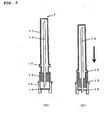
- FIG. 2(D) is a view showing a state of the pouring device (needle unit) before being used
- FIG. 2 (E) is a view showing a state in which an injection substance needle of a pouring part constituting the pouring device is communicated with a container main body.
- the double-ended needle 14 is fixed in the case 11 provided with a stopper 12 through a hub 13 composed of an elastic material of rubber or the like.
- a stopper 16 made of an elastic material of rubber or the like is set.
- the double-ended needle 14 pouring contents is held in a sterile state in the case 11.
- the protective case 6 is opened by twisting it with fingers.
- the case 11 of the pouring device 5 is pressed down to a position of FIG. 2 (E)
- one end of the double-ended needle 14 of the pouring part fixed to the hub 13 passes through the stopper 16 to be communicated with the container body 2.
- the container main body 2 is folded at the folding guide line 3, thereby the injection substance can be poured completely.
- the injection substance package 1 can be self-supported under the condition that the double-sided needle 14 is communicated with the container main body 2.
- the package before used for a patient after the opening of the protective case 6 of the package, the package can be self-supported temporarily in a storage case or the like without being contaminated.
- FIG. 3 are enlarged cross-sectional views showing another example of the sterile package of the present invention, in which the pouring device (needle unit) 5 is shown in an enlarged state with the protective case 6 of the package being opened.
- FIG. 3(A) shows a state of the pouring device 5 before being used
- FIG. 3(B) shows a state in which the double-ended needle 14 of the pouring part is pushed in toward the container main body, thereby the double-ended needle 14 can be communicated with the container main body 2.
- FIG. 3(C) shows a state in which the case 11 of the pouring device 5 is removed after the double-ended needle 14 is pushed in, thereby the injection substance in the container main body can be poured.
- a check part such as a check valve 17 is provided to a lower end of the stopper 16 provided in the connecting portion 15 with respect to the plastic container main body 2 of the pouring device 5, that is, at the lower end of the pouring device 5.
- the check valve 17 the contents can be poured out of the container main body from the plastic container main body 2 via the double-ended needle 14, and the contents poured out or other drugs can be prevented from flowing back to the container main body 2 via the double-ended needle 14.
- other contents such as a hazardous material (e. g. , stimulant) can be prevented from being aspired in the container after the use of the sterile package of the present invention and abusing of the container can be prevented.
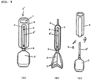
- FIG. 4 show another example of the sterile package of the present invention
- FIG. 4 (A) is a front view of the package
- FIG. 4(B) is a partial cross-sectional side view of the package
- FIG. 4(C) shows a state in which the protective case of the pouring device of the package is opened.
- a pouring device 5' only composed of a cylindrical pouring part with a tip end blocked is used in place of the pouring device (needle unit) 5 composed of the double-ended needle 14 of the pouring part or the like and the case 11.
- the pouring device 5' is communicated with the container main body 2, without the case 11 in the needle unit 5, and a tip end 9 thereof is provided with an annular thin portion 8 for opening the tip end 9.
- a package 1' is used, as shown in FIG. 4 (C)
- the protective case 6 is opened by twisting it with fingers, and the thin portion 8 is folded to be removed to open the tip end 9.
- the container main body 2 is folded at the folding guide line 3, thereby the contents can be poured completely.
- the sterile package 1' can be used preferably for storing, for example, a gel-shaped or cream-shaped suppository.
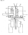
- a production apparatus 21 stores, in a sterile box 22, a nozzle unit 23 having a nozzle 24 connected to a supply pipe P1 of sterile air for blow molding and a content supply pipe P2, and a pouring device insertion unit 26 having a pouring device magazine 25.
- the nozzle unit 23 and the pouring device insertion unit 26 can reciprocate alternately in a horizontal direction by driving devices M1 and M2, respectively.
- the mold 30 is composed of a mold 31 for a protective case, a mold 32 for a plastic container main body, and a mold 33 for heat sealing for heat-sealing a connecting portion, which is disposed between the mold 31 for a protective case and the mold 32 for a container main body (see FIG. 6).
- the sterile package of the present invention can be produced by the following steps (1) to (11), for example, using the production apparatus 21(see FIG. 6).
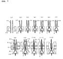
- FIG. 7 are schematic views illustrating another example of the steps of producing the sterile package of the present invention.
- the above-mentioned production steps (1) to (12) corresponding to FIG. 7 are obtained by modifying the production steps (1) to (11) corresponding to FIG. 6.
- the cross-sectional shape of a parison may be deformed due to a change in an internal pressure or the like caused by the drawdown of the parison or the taking in/out of the nozzle and the pouring device insertion unit. Consequently, there arise a problem that the nozzle and the pouring device insertion unit or the pouring device come into contact with the parison inner wall, which makes it difficult to mold a sterile package.
- the nozzle and the pouring device insertion unit are inserted/retracted while the PCA is blown, thereby a sterile package can be produced with good efficiency while avoiding such a problem.
- the introduction of the PCA in the production steps of FIG. 7 may be performed continuously between the above-mentioned steps (3) and (9). In this case, it is not necessary to switch the introduction and suspension of the PCA for each step, and a sterile package can be produced with good efficiency while avoiding the above-mentioned problem.
- a label (not shown) or the like is attached to a hole remaining after the blow pin 34 is pulled out. At this time, the sterility in the protective case 6 may be impaired. However, in the sterile packages of FIGS. 2 and 3, by using the pouring device (needle unit) 5 storing the double-ended needle 14 that is a contents-pouring device in the case 11 in a sterile state, there is no fear that the pouring device 5 may be contaminated.
- a production apparatus of a horizontal rotary system in which a number of molds are arranged successively so as to rotate or a shuttle system in which two molds reciprocate is used, the parison is extruded into the mold and the mold is clamped (corresponding to the step (2) of FIG. 6 or FIG. 7), the parison is cut, and the mold is moved, thereby the blow molding of the container main body and the filling of the contents are performed. It is practically impossible to dispose all the steps of such a production apparatus under a sterile environment, and thus, during cutting of the parison or the movement of the mold, the inside of the parison disposed in the mold may be contaminated with an outside air.
- a sterile package is produced without cutting a parison, using a production apparatus of a compact size with a simple configuration. This can greatly reduce the production cost with a simple management of the sterile state of the apparatus.
- the container main body 2 and the protective case 6 of the pouring device 5 are formed integrally. Therefore, the opening of the package caused by an external force during production or distribution, and the mischief and unauthorized opening of a package can be prevented.
- thermoplastic resin used for constituting a plastic container can be generally used.
- a material constituting the plastic container main body 2 and the protective case 6 formed integrally therewith any of the thermoplastic resin used for constituting a plastic container can be generally used.
- a material include polyolefins such as low, middle, or high-density polyethylene, polypropylene, an ethylene-propylene copolymer, an ethylene-vinyl acetate copolymer (EVA), a saponified EVA, an ethylene-ethyl acrylate copolymer (EEA), an ion cross-linked olefin copolymer (ionomer); an aromatic vinyl copolymer such as polystyrene, a styrene-butadiene copolymer; a vinyl halide polymer such as polyvinyl chloride and vinylidene chloride resin; polyacrylic resin; a nitrile copolymer such as an acrylonitrile-st
- the plastic container main body and the protective case of the present invention can have a single-layer configuration composed of one kind of resin layer or a multi-layered configuration composed of a plurality of resin layers.
- a container with a multi-layered configuration including a gas barrier resin layer made of polyvinylidene chloride, a saponified EVA, polyamide resin, or a cyclic olefin copolymer, as an intermediate layer.
- a container with a multi-layered configuration including an oxygen absorbing resin layer containing an oxidizable polymer or the like can be used.
- Such a container with a multi-layered configuration can be produced using a multi-layered parison obtained using a die for multi-layer blowing by a conventional method in the steps shown in FIG. 6 or FIG. 7.
Landscapes
- Engineering & Computer Science (AREA)
- Mechanical Engineering (AREA)
- Health & Medical Sciences (AREA)
- Manufacturing & Machinery (AREA)
- Life Sciences & Earth Sciences (AREA)
- Veterinary Medicine (AREA)
- Public Health (AREA)
- General Health & Medical Sciences (AREA)
- Animal Behavior & Ethology (AREA)
- Pharmacology & Pharmacy (AREA)
- Hematology (AREA)
- Heart & Thoracic Surgery (AREA)
- Biomedical Technology (AREA)
- Anesthesiology (AREA)
- Vascular Medicine (AREA)
- Ceramic Engineering (AREA)
- Packages (AREA)
- Medical Preparation Storing Or Oral Administration Devices (AREA)
- Infusion, Injection, And Reservoir Apparatuses (AREA)
- Basic Packing Technique (AREA)
- Blow-Moulding Or Thermoforming Of Plastics Or The Like (AREA)
- Moulds For Moulding Plastics Or The Like (AREA)
Abstract
Description
- The present invention relates to a sterile package which includes a contents-pouring device integrally housed therein, a method of producing the sterile package, and its production apparatus.
- Conventionally, a plastic container with a pouring device is known, in which the contents such as drugs and unregulated drugs are housed in a small volume to be used up at one time in the container, and a pouring device such as a needle for pouring the contents is attached to an inlet of the container (for example, see
Patent Documents 1 and 2)
Further, it is also known that, when such a plastic container with a pouring device is produced, the container is filled with contents simultaneously at the time of molding the container in terms of sanitary supervision (see Patent Document 3) - Patent Document1:
Japanese Examined Utility Model Publication No. Sho 35-24295 - Patent Document 2: Japanese Examined Patent Publication No. Sho
61-2380 - Patent Document 3:
JP 2002-128126 A - However, those containers with a pouring device have problems in that the container is opened due to an external force caused by a drop impact or the like in the course of production and distribution, and the container lacks a tamper-evident property for preventing mischief and unauthorized opening, and the like.
Therefore, in the plastic container with a pouring device filled with contents, an attempt is made so as to protect a pouring device and obtain a tamper-evident property by using a cladding such as a carton or a pouch, or by using another part such as a tape and a shrink-label. However, a method using a cladding and another part requires additional steps, which causes an increase in cost. - Then, in order to use up the contents housed in such a container at one time, it is necessary that the whole amount of contents be poured by crushing a container main body with fingers. However, in a case of a container in a cylindrical shape or the like, a bottom portion of the container becomes an obstacle, which makes it difficult to pour the contents completely.
Thus, in a conventional container with a pouring device, the pourability of contents is enhanced by adopting a container without a bottom portion, and thus, the container is not allowed to be self-supported. - Accordingly, the object of the present invention is to provide a sterile package which includes a pouring device integrally housed therein, in which the protection property of the pouring device, and the pourability of contents and tamper-evident property are enhanced. Another object of the present invention is to provide a method of producing the sterile package and its production apparatus, capable of continuously performing molding of a plastic container main body to be filled with contents, sterile filling of the contents, molding of a protective case that is formed integrally with the container main body, and storage of a pouring device in the protective case.
- In order to solve the above-mentioned problems, the present invention employs the following
constituents 1 to 13. - 1. A sterile package, comprising: a plastic container main body with a folding guide line formed to be filled with contents sterilely; a protective case integrally molded with the plastic container main body; and a pouring device stored in the protective case.
- 2. A sterile package according to
Item 1, in which the pouring device is stored in the protective case sterilely. - 3. A sterile package according to
Item 1, wherein the pouring device comprising a pouring part stored in a case sterilely and being stored in the protective case. - 4. A sterile package according to any one of
Items 1 to 3, further including a check part provided to a lower end of the pouring device. - 5. A method of producing a sterile package, including the following steps of:
- (1) disposing a parison in a mold for a plastic container main body;
- (2) blowing sterile air from a nozzle inserted in the parison to blow-mold the plastic container main body;
- (3) filling the plastic container main body with the contents from the nozzle and retracting the nozzle;
- (4) inserting a pouring device in the parison located above the plastic container main body;
- (5) clamping a mold for a protective case; and
- (6) forming the protective case with the parison located above the plastic container main body.
- 6. The method of producing a sterile package according to
Item 5, in which, at least in the above-mentioned steps (2) and (3), the nozzle is inserted or retracted while the sterile air is blown into the parison through the nozzle in such a manner that the nozzle does not come into contact with an inner wall of the parison. It is preferable that the pressure of the sterile air blown through the nozzle be set to be about 0.001 to 0.1 MPa. - 7. The method of producing a sterile package according to
Items - 8. A method of producing a sterile package according to any one of
Items 5 to 7, in which, in the step (5), the parison between a lower portion of the pouring device and an upper portion of the plastic container main body is heat-sealed previously. - 9. The method of producing a sterile package according to any one of
Items 5 to 8,in which, in the step (6), the protective case is formed by vacuum molding. - 10. The method of producing a sterile package according to
Item 9, in which, in the above-mentioned step (6), a blow pin is pierced in the protective case from a side surface of the protective case, and vacuum molding is performed while the sterile air is blown into the case from the blow pin. It is preferable that the pressure of the sterile air blown from the blow pin be set to be about 0.1 to 0.6 MPa. - 11. The method of producing a sterile package according to any one of
Items 5 to 10, in which the parison is a multi-layered parison including a gas barrier resin layer. - 12. A production apparatus of a sterile package, including a nozzle unit that supplies sterile air for blow molding and fills contents and a pouring device insertion unit in a sterile box, in which a parison extrusion die to be connected below the sterile box, a mold for a protective case, and a mold for a plastic container main body are successively disposed.
- 13. The production apparatus of a sterile package according to
Item 12, in which a mold for heat sealing is provided between the mold for the protective case and the mold for the plastic container main body. - The present invention exhibits the following remarkable effects by employing the above-mentioned constituents.
- (1) A sterile package of the present invention is excellent in a protection property of a pouring device and a tamper-evident property, and can prevent the opening of the package due to an external force in the course of production and distribution of the package, and the mischief and unauthorized opening of the package.
- (2) In the sterile package of the present invention, a folding guide line is formed in a container main body, thereby contents can be easily poured completely.
- (3) In the sterile package of the present invention, a backflow during pouring of the contents can be prevented by providing a check part to a lower end of the pouring device. Further, other contents such as a hazardous material (e.g., a stimulant) are prevented from being aspired after the use of the container and abusing of the package is prevented.
- (4) According to a method of producing a sterile package of the present invention, molding of a plastic container main body to be filled with contents, sterile filling of the contents, molding of a protective case that is formed integrally with the container main body, and storage of a pouring device in the protective case can be performed continuously. Therefore, the sterile package can be produced efficiently at a low cost.
- (5) A production apparatus of a sterile package of the present invention can be designed to be a compact size with a simple configuration, and the sterile state of the apparatus is managed easily, which can reduce a production cost significantly.
-
- [FIG. 1] Views showing one example of a sterile package (disposable injection substance package) of the present invention.
- [FIG. 2] Enlarged cross-sectional views showing a pouring device (needle unit) of the sterile package of FIG. 1.
- [FIG. 3] Enlarged cross-sectional views showing a pouring device (needle unit) of another example of the sterile package (disposable injection substance package) of the present invention.
- [FIG. 4] Views showing another example of the sterile package of the present invention.
- [FIG. 5] Schematic view showing one example of a production apparatus of the sterile package of FIG. 1.
- [FIG. 6] Diagrams illustrating one example of a method of producing a sterile package using the production apparatus of FIG. 5.
- [FIG. 7] Diagrams illustrating another example of the method of producing a sterile package of the present invention.
-
- 1,1'
- sterile package
- 2
- plastic container main body
- 3
- folding guide line
- 4,15
- connecting portion
- 5
- pouring device (needle unit)
- 5'
- pouring device (pouring part)
- 6
- protective case
- 7
- label
- 8
- thin portion
- 9
- tip end
- 11
- case
- 12
- stopper
- 13
- hub
- 14
- double-ended needle
- 16
- stopper
- 17
- check valve
- 21
- sterile package production apparatus
- 22
- sterile box
- 23
- nozzle unit
- 24
- nozzle
- 25
- pouring device magazine
- 26
- pouring device insertion unit
- 27
- parison
- 28
- die head
- 29
- parison extruder
- 30
- mold
- 31
- mold for protective case
- 32
- mold for container main body
- 33
- mold for heat sealing
- 34
- blow pin
- M1,M2
- driving device
- P1
- supply pipe of sterile air
- P2
- contents supply pipe
- Hereinafter, an example in which the present invention is applied to a disposable injection substance package will be described with reference to the drawings. It should be noted that the present invention is not limited to the following specific examples.
FIGS. 1 and 2 are views showing one example of a sterile package (disposable injection substance package) of the present invention. FIG. 1(A) is a front view of a package, FIG. 1(B) is a partial cross-sectional side view, and FIG. 1(C) is a view showing a state in which a protective case of a pouring device of the package is opened. Further, FIG. 2 are enlarged cross-sectional views of a pouring device (needle unit) of the package. FIG. 2(D) is a view showing a state of the pouring device (needle unit) before being used, and FIG. 2 (E) is a view showing a state in which an injection substance needle of a pouring part constituting the pouring device is communicated with a container main body. - The
injection substance package 1 is obtained by integrally molding acontainer body 2 provided with afolding guide line 3 and aprotective case 6 storing a pouring device (needle unit) 5 composed of a double-endedneedle 14 or the like of the pouring part for pouring contents and acase 11. Thecontainer body 2 is filled with an injection substance sterilely during molding of thecontainer body 2. Further, alabel 7 displaying the filled injection substance is provided on an upper portion of theprotective case 6. - As shown in FIG. 2, in the pouring
device 5, the double-endedneedle 14 is fixed in thecase 11 provided with astopper 12 through a hub 13 composed of an elastic material of rubber or the like. At a lower end of a connecting portion 15 with respect to thecontainer body 2 of the pouringdevice 5, astopper 16 made of an elastic material of rubber or the like is set. In the pouringdevice 5, the double-endedneedle 14 pouring contents is held in a sterile state in thecase 11. - As shown in FIG. 1(C), when the
injection substance package 1 is used, first, theprotective case 6 is opened by twisting it with fingers. Next, when thecase 11 of the pouringdevice 5 is pressed down to a position of FIG. 2 (E), one end of the double-endedneedle 14 of the pouring part fixed to the hub 13 passes through thestopper 16 to be communicated with thecontainer body 2. Then, when thecase 11 is removed and the other end of the double-endedneedle 14 is inserted into the vein or the like of a patient, and thecontainer body 2 is held with fingers, the containermain body 2 is folded at thefolding guide line 3, thereby the injection substance can be poured completely.
Theinjection substance package 1 can be self-supported under the condition that the double-sided needle 14 is communicated with the containermain body 2. Thus, before used for a patient after the opening of theprotective case 6 of the package, the package can be self-supported temporarily in a storage case or the like without being contaminated. - FIG. 3 are enlarged cross-sectional views showing another example of the sterile package of the present invention, in which the pouring device (needle unit) 5 is shown in an enlarged state with the
protective case 6 of the package being opened. FIG. 3(A) shows a state of the pouringdevice 5 before being used, and FIG. 3(B) shows a state in which the double-endedneedle 14 of the pouring part is pushed in toward the container main body, thereby the double-endedneedle 14 can be communicated with the containermain body 2. Then, FIG. 3(C) shows a state in which thecase 11 of the pouringdevice 5 is removed after the double-endedneedle 14 is pushed in, thereby the injection substance in the container main body can be poured.
In thesterile package 1 of the present example, a check part such as acheck valve 17 is provided to a lower end of thestopper 16 provided in the connecting portion 15 with respect to the plastic containermain body 2 of the pouringdevice 5, that is, at the lower end of the pouringdevice 5.
By providing thecheck valve 17, the contents can be poured out of the container main body from the plastic containermain body 2 via the double-endedneedle 14, and the contents poured out or other drugs can be prevented from flowing back to the containermain body 2 via the double-endedneedle 14.
Then, by providing thecheck valve 17 to a lower end of the pouringdevice 5, other contents such as a hazardous material (e. g. , stimulant) can be prevented from being aspired in the container after the use of the sterile package of the present invention and abusing of the container can be prevented. - FIG. 4 show another example of the sterile package of the present invention, and FIG. 4 (A) is a front view of the package, FIG. 4(B) is a partial cross-sectional side view of the package, and FIG. 4(C) shows a state in which the protective case of the pouring device of the package is opened.
In this example, in the sterile package of FIG. 1, a pouring device 5' only composed of a cylindrical pouring part with a tip end blocked is used in place of the pouring device (needle unit) 5 composed of the double-endedneedle 14 of the pouring part or the like and thecase 11. The pouring device 5' is communicated with the containermain body 2, without thecase 11 in theneedle unit 5, and atip end 9 thereof is provided with an annularthin portion 8 for opening thetip end 9. When a package 1' is used, as shown in FIG. 4 (C), theprotective case 6 is opened by twisting it with fingers, and thethin portion 8 is folded to be removed to open thetip end 9. Then, when the pouring device 5' is applied to an affected portion of a patient, and the containermain body 2 is held with fingers, the containermain body 2 is folded at thefolding guide line 3, thereby the contents can be poured completely. The sterile package 1' can be used preferably for storing, for example, a gel-shaped or cream-shaped suppository. - Next, referring to the drawings, the production apparatus and production steps of the sterile package of the present invention will be described. FIG. 5 is a schematic view showing one example of the production apparatus of the sterile package of the present invention. FIG. 6 are schematic views illustrating one example of the steps of producing the sterile package of the present invention, using the production apparatus.
- A production apparatus 21 stores, in a
sterile box 22, a nozzle unit 23 having anozzle 24 connected to a supply pipe P1 of sterile air for blow molding and a content supply pipe P2, and a pouringdevice insertion unit 26 having a pouring device magazine 25. The nozzle unit 23 and the pouringdevice insertion unit 26 can reciprocate alternately in a horizontal direction by driving devices M1 and M2, respectively. - A
parison extruder 29 having a diehead 28 extruding aparison 27 is set below thesterile box 22 . On an inner side surface of thedie head 28, there are provided an exit port 34 capable of discharging sterile air so that it becomes an ascending airstream from the die head side to thesterile box 22 so as to enhance sterility in thesterile box 22, and an exit port 35 capable of discharging sterile air so that it becomes a descending airstream so as to stabilize the shape of the parison by pressuring the inside of the parison. Further, amold 30 for integrally molding the plastic container body and the protective case of the pouring device is provided below the parison extruder. Themold 30 is composed of a mold 31 for a protective case, a mold 32 for a plastic container main body, and a mold 33 for heat sealing for heat-sealing a connecting portion, which is disposed between the mold 31 for a protective case and the mold 32 for a container main body (see FIG. 6). - The sterile package of the present invention can be produced by the following steps (1) to (11), for example, using the production apparatus 21(see FIG. 6).
- (1) The
parison 27 is extruded to themold 30. - (2) The mold 32 for a plastic container main body is clamped (first mold clamping).
- (3) The
nozzle 24 is inserted into the upper portion of theparison 27. - (4) The container main body is blow-molded with sterile air.
- (5) The injection substance (contents) is filled in the container
main body 2 from thenozzle 24. - (6) After the
nozzle 24 is retracted from the upper portion of theparison 27, the position of a nozzle unit 23 in thesterile box 22 is exchanged with the position of a pouringdevice insertion unit 26. - (7) The pouring
device 5 is inserted into the upper portion of theparison 27 by the pouringdevice insertion unit 26. - (8) The mold 33 for heat sealing is clamped, and the connecting
portion 4 of the containermain body 2 and theprotective case 6 is heat-sealed. - (9) The mold 31 for a protective case is clamped, and the upper portion of the
protective case 6 is heat-sealed, thereby the pouringdevice 5 is sealed in theprotective case 6. - (10) The
protective case 6 is molded by vacuum molding in the mold 31 for a protective case. - (11) All the molds are opened, and the parisons in the lower portion of the
container body 2 and the upper portion of theprotective case 6 are cut to obtain an intended sterile package.
Accordingly, the sterility of the contents of the containermain body 2 and the inside of theprotective case 6 is kept, and in a case where the pouring device (needle unit) 5 storing the double-endedneedle 14 that is a pouring part of contents in thecase 11 as shown in FIGS. 2 and 3 is used, or in a case where a pouring device 5' only composed of a cylindrical pouring part with a tip end blocked as shown in FIG. 4 is used, there is no fear that the pouring part may be contaminated before being used. - FIG. 7 are schematic views illustrating another example of the steps of producing the sterile package of the present invention.
- (1) The
parison 27 is extruded to themold 30. - (2) The mold 32 for a plastic container main body is clamped (first mold clamping).
- (3), (4) The
nozzle 24 is inserted into the upper portion of theparison 27, while sterile air (Parison Control Air: hereinafter, referred to as "PCA") at a low pressure (about 0.001 to 0.1 MPa) is blown from a nozzle tip end portion to prevent thenozzle 24 from coming into contact with the inner wall of the parison. - (5) The container main body is blow-molded with sterile air.
- (6) The injection substance (contents) is filled in the container
main body 2 from thenozzle 24. - (7) While the PCA is blown into the
parison 27, after thenozzle 24 is retracted from the upper portion of theparison 27, the position of a nozzle unit 23 in thesterile box 22 is exchanged with the position of a pouringdevice insertion unit 26. - (8) While the PCA at a low pressure (about 0.001 to 0.1 MPa) is blown into the
parison 27 through air holes provided on the side wall of the pouringdevice insertion unit 26, the pouringdevice 5 is inserted into the upper portion of theparison 27 by the pouringdevice insertion unit 26. - (9) While the PCA is blown into the
parison 27, the pouringdevice insertion unit 26 is retracted to clamp the mold 33 for heat sealing, thereby the connectingportion 4 of the containermain body 2 and theprotective portion 6 is heat-sealed. - (10) The mold 31 for a protective case is clamped, and the upper portion of the
protective case 6 is heat-sealed, thereby the pouringdevice 5 is sealed in theprotective case 6. - (11) A blow pin 34 is pierced into the
protective case 6 from the side surface of theprotective case 6, and while sterile air (about 0.1 to 0. 6 MPa) is blown from the blow pin 34 to theprotective case 6, theprotective case 6 is molded by vacuum molding in the mold 31 for a protective case. - (12) All the molds are opened, and the parisons in the lower portion of the
container body 2 and the upper portion of theprotective case 6 are cut to obtain an intended sterile package. - The above-mentioned production steps (1) to (12) corresponding to FIG. 7 are obtained by modifying the production steps (1) to (11) corresponding to FIG. 6.
In the first mold clamping step (2) and in the steps (3), (7), (8), and (9) of the insertion and retraction of the nozzle and the pouring device insertion unit, the cross-sectional shape of a parison may be deformed due to a change in an internal pressure or the like caused by the drawdown of the parison or the taking in/out of the nozzle and the pouring device insertion unit. Consequently, there arise a problem that the nozzle and the pouring device insertion unit or the pouring device come into contact with the parison inner wall, which makes it difficult to mold a sterile package. In the production steps of FIG. 7, the nozzle and the pouring device insertion unit are inserted/retracted while the PCA is blown, thereby a sterile package can be produced with good efficiency while avoiding such a problem.
The introduction of the PCA in the production steps of FIG. 7 may be performed continuously between the above-mentioned steps (3) and (9). In this case, it is not necessary to switch the introduction and suspension of the PCA for each step, and a sterile package can be produced with good efficiency while avoiding the above-mentioned problem. - Further, in a case of molding the
protective case 6 only by vacuum molding, theprotective case 6 is reduced in a pressure during molding. Therefore, a resistance preventing the molding of the case is generated, which makes it difficult to mold the protective case having a precise shape.
In the above-mentioned step (11), the blow pin 34 is pierced into theprotective case 6 from the side surface of theprotective case 6, and sterile air (about 0.1 to 0.6 MPa) is blown from the blow pin 34 to theprotective case 6, thereby the inside of theprotective case 6 is set in a positive pressure. Thus, when the vacuum molding of theprotective case 6 is performed, theprotective case 6 having a precise shape can be molded without a resistance caused by a reduced pressure. A label (not shown) or the like is attached to a hole remaining after the blow pin 34 is pulled out. At this time, the sterility in theprotective case 6 may be impaired. However, in the sterile packages of FIGS. 2 and 3, by using the pouring device (needle unit) 5 storing the double-endedneedle 14 that is a contents-pouring device in thecase 11 in a sterile state, there is no fear that the pouringdevice 5 may be contaminated. - In the conventional technique, a production apparatus of a horizontal rotary system in which a number of molds are arranged successively so as to rotate or a shuttle system in which two molds reciprocate is used, the parison is extruded into the mold and the mold is clamped (corresponding to the step (2) of FIG. 6 or FIG. 7), the parison is cut, and the mold is moved, thereby the blow molding of the container main body and the filling of the contents are performed. It is practically impossible to dispose all the steps of such a production apparatus under a sterile environment, and thus, during cutting of the parison or the movement of the mold, the inside of the parison disposed in the mold may be contaminated with an outside air.
- According to the present invention, a sterile package is produced without cutting a parison, using a production apparatus of a compact size with a simple configuration. This can greatly reduce the production cost with a simple management of the sterile state of the apparatus.
Further, in the sterile package of the present invention, the containermain body 2 and theprotective case 6 of the pouringdevice 5 are formed integrally. Therefore, the opening of the package caused by an external force during production or distribution, and the mischief and unauthorized opening of a package can be prevented. - In the present invention, there is no particular limitation on a material constituting the plastic container
main body 2 and theprotective case 6 formed integrally therewith, and any of the thermoplastic resin used for constituting a plastic container can be generally used. Examples of such a material include polyolefins such as low, middle, or high-density polyethylene, polypropylene, an ethylene-propylene copolymer, an ethylene-vinyl acetate copolymer (EVA), a saponified EVA, an ethylene-ethyl acrylate copolymer (EEA), an ion cross-linked olefin copolymer (ionomer); an aromatic vinyl copolymer such as polystyrene, a styrene-butadiene copolymer; a vinyl halide polymer such as polyvinyl chloride and vinylidene chloride resin; polyacrylic resin; a nitrile copolymer such as an acrylonitrile-styrene copolymer and an acrylonitrile-styrene-butadiene copolymer; polyamides such asnylon 6, nylon 66, and para or methaxylyleneadipamide; polyesters such as polyethylene terephtharate, polytrimethylene terephthalate, polybutylene terephtharate, and polyethylene naphtharate; various kinds of polycarbonates; fluorine resin; polyacetals such as polyoxymethylene; biodegrative reins such as polybutylene succinate, polyethylenesuccinate, polyhydroxybutyrate, polycaprolactone, and polylactic acid.
Examples of the preferable thermoplastic resin include polyolefin resin, in particular, polypropylene resin such as polypropylene, an ethylene-propylene copolymer. - The plastic container main body and the protective case of the present invention can have a single-layer configuration composed of one kind of resin layer or a multi-layered configuration composed of a plurality of resin layers.
In a case where the contents stored in the container main body require a gas barrier property as in medical drugs, it is preferable to produce a container with a multi-layered configuration including a gas barrier resin layer made of polyvinylidene chloride, a saponified EVA, polyamide resin, or a cyclic olefin copolymer, as an intermediate layer. Further, in a case where a much higher gas barrier property is required, a container with a multi-layered configuration including an oxygen absorbing resin layer containing an oxidizable polymer or the like can be used. Such a container with a multi-layered configuration can be produced using a multi-layered parison obtained using a die for multi-layer blowing by a conventional method in the steps shown in FIG. 6 or FIG. 7.
Claims (13)
- A sterile package, comprising:a plastic container main body with a folding guide line formed therein to be filled with contents sterilely;a protective case integrally molded with the plastic container main body; anda pouring device stored in the protective case.
- A sterile package according to claim 1, wherein the pouring device is stored in the protective case sterilely.
- A sterile package according to claim 1, wherein the pouring device comprising a pouring part stored in a case sterilely and being stored in the protective case.
- A sterile package according to any one of claims 1 to 3, further comprising a check part provided to a lower end of the pouring device.
- A method of producing a sterile package, comprising the following steps of:(1) disposing a parison in a mold for a plastic container main body;(2) blowing sterile air from a nozzle inserted in the parison to blow-mold the plastic container main body;(3) filling the plastic container main body with the contents from the nozzle and retracting the nozzle;(4) inserting a pouring device in the parison located above the plastic container main body;(5) clamping a mold for a protective case; and(6) forming the protective case with the parison located above the plastic container main body.
- A method of producing a sterile package according to claim 5, wherein, at least in the steps (2) and (3), the nozzle is inserted/retracted while the sterile air is blown in the parison from the nozzle so that the nozzle does not come into contact with an inner wall of the parison.
- A method of producing a sterile package according to claim 5 or 6, wherein, at least in the step (4), a pouring device insertion unit is inserted/retracted while the sterile air is blown in the parison through an air hole provided to the pouring device insertion unit so that the pouring device insertion unit and the pouring device do not come into contact with the inner wall of the parison.
- A method of producing a sterile package according to any one of claims 5 to 7, wherein, in the step (5), the parison between a lower portion of the pouring device and an upper portion of the plastic container main body is heat-sealed previously.
- A method of producing a sterile package according to any one of claims 5 to 8, wherein, in the step (6), the protective case is formed by vacuum molding.
- A method of producing a sterile package according to claim 9, wherein, in the step (6), a blow pin is pierced in the protective case from a side surface of the protective case, and vacuum molding is performed while the sterile air is blown into the case trough the blow pin.
- A method of producing a sterile package according to any one of claims 5 to 10, wherein the parison is a multi-layered parison including a gas barrier resin layer.
- A production apparatus of a sterile package, comprising a nozzle unit that supplies sterile air for blow molding and fills contents and a pouring device insertion unit in a sterile box, wherein a parison extrusion die to be connected below the sterile box, a mold for a protective case, and a mold for a plastic container main body are successively disposed.
- A production apparatus of a sterile package according to claim 12, wherein a mold for heat sealing is provided between the mold for the protective case and the mold for the plastic container main body.
Applications Claiming Priority (2)
| Application Number | Priority Date | Filing Date | Title |
|---|---|---|---|
| JP2005031296 | 2005-02-08 | ||
| PCT/JP2006/301872 WO2006085490A1 (en) | 2005-02-08 | 2006-02-03 | Sterile package, process for producing the same, and production apparatus |
Publications (3)
| Publication Number | Publication Date |
|---|---|
| EP1847242A1 true EP1847242A1 (en) | 2007-10-24 |
| EP1847242A4 EP1847242A4 (en) | 2013-04-03 |
| EP1847242B1 EP1847242B1 (en) | 2015-06-17 |
Family
ID=36793064
Family Applications (1)
| Application Number | Title | Priority Date | Filing Date |
|---|---|---|---|
| EP06713015.3A Ceased EP1847242B1 (en) | 2005-02-08 | 2006-02-03 | Sterile package, process for producing the same, and production apparatus |
Country Status (6)
| Country | Link |
|---|---|
| US (1) | US7883660B2 (en) |
| EP (1) | EP1847242B1 (en) |
| JP (2) | JP4962313B2 (en) |
| KR (1) | KR20070107716A (en) |
| CN (1) | CN101115458B (en) |
| WO (1) | WO2006085490A1 (en) |
Cited By (5)
| Publication number | Priority date | Publication date | Assignee | Title |
|---|---|---|---|---|
| DE102008020209A1 (en) * | 2008-04-22 | 2009-10-29 | Friedrich Sanner Gmbh & Co. Kg | Pipette for sterile administration of medicines and for interlock, has base with chamber for admission of material, where chamber opens into discharge opening which is formed in discharge opening section |
| EP2266521A4 (en) * | 2008-03-14 | 2011-03-16 | Otsuka Pharma Co Ltd | PLASTIC BULB AND CONTAINER IN COLOR PLASTIC MATERIAL |
| DE102012021525A1 (en) | 2012-10-31 | 2014-04-30 | Kocher-Plastik Maschinenbau Gmbh | Sealing arrangement and such an associated container |
| WO2014078259A1 (en) * | 2012-11-16 | 2014-05-22 | Illinois Tool Works Inc. | Method for producing a blow moulded fuel filler system for a motor vehicle and fuel filler system for a motor vehicle |
| DE102013001182A1 (en) * | 2013-01-24 | 2014-07-24 | Bernd Hansen | Method for manufacturing a job device |
Families Citing this family (28)
| Publication number | Priority date | Publication date | Assignee | Title |
|---|---|---|---|---|
| JP5218722B2 (en) * | 2006-09-06 | 2013-06-26 | 東洋製罐株式会社 | Manufacturing method and apparatus for aseptic filling package |
| JP5041150B2 (en) * | 2007-10-31 | 2012-10-03 | 東洋製罐株式会社 | Packaging container |
| CN102836066B (en) * | 2008-03-14 | 2014-11-05 | 株式会社大塚制药工厂 | Plastic ampoule and colored plastic container |
| JP5292609B2 (en) * | 2008-08-07 | 2013-09-18 | 東洋製罐株式会社 | Method for verifying "sterility level of container" in aseptic filling system and aseptic filling system |
| EP2418153B1 (en) * | 2009-04-10 | 2015-11-11 | Orihiro Engineering Co., Ltd. | Aseptic filling packaging machine and aseptic filling packaging method |
| EP2515822A4 (en) * | 2009-12-24 | 2013-06-05 | Bm Gol Pty Ltd | SINGLE-USE CONTAINERS AND USES THEREOF |
| FR2967136B1 (en) * | 2010-11-08 | 2013-11-01 | Unither Dev | METHOD FOR MANUFACTURING BRANDED FIELDS, CHAIN FOR MANUFACTURING BRANDED FIELDS AND FIELDS MARKED |
| JP5654385B2 (en) * | 2011-02-28 | 2015-01-14 | 大和製罐株式会社 | Ampoule made of synthetic resin and manufacturing method thereof |
| WO2014090796A1 (en) * | 2012-12-10 | 2014-06-19 | Fresenius Kabi Deutschland Gmbh | Process for producing and assembling a medical operations syringe |
| US9867973B2 (en) * | 2013-06-17 | 2018-01-16 | Medline Industries, Inc. | Skin antiseptic applicator and methods of making and using the same |
| US11027862B2 (en) * | 2014-06-23 | 2021-06-08 | Woodstock Sterile Solutions, Inc. | Cold blow-fill-seal packaging system and process |
| BR102015023751B1 (en) | 2014-09-16 | 2020-11-03 | Brevetti Angela S.R.L | process for producing a container equipped with a closure system |
| WO2016145206A1 (en) | 2015-03-10 | 2016-09-15 | Regeneron Pharmaceuticals, Inc. | Aseptic piercing system and method |
| CN108348685B (en) | 2015-07-02 | 2021-07-30 | 科斯卡家族有限公司 | Disposable delivery devices prefilled with reconstituted reagents |
| KR101776721B1 (en) | 2015-07-07 | 2017-09-08 | 현대자동차 주식회사 | Method and apparatus of controlling vehicle including driving motor |
| KR102487355B1 (en) | 2016-04-25 | 2023-01-11 | 코스카 패밀리 리미티드 | medical delivery system |
| CN109562233B (en) * | 2016-08-02 | 2022-04-15 | 赛诺菲-安万特德国有限公司 | drug delivery device |
| DE102016122061A1 (en) * | 2016-11-16 | 2018-05-17 | Schott Ag | Process for the preparation of glass vials with low delamination tendency under the influence of a purging gas flow |
| IT201700039384A1 (en) * | 2017-04-10 | 2018-10-10 | Brev Angela Srl | INSERT FOR PACKAGING OF CLISMS PRE-FILLED, CLISMS PRE-FILLED AND PROCEDURE FOR THE CREATION OF CLISMS PRE-FILLED |
| ES2919934T3 (en) | 2017-05-05 | 2022-07-29 | Regeneron Pharma | Autoinjector and related procedures for use |
| CN107693903A (en) * | 2017-11-16 | 2018-02-16 | 中国大冢制药有限公司 | A kind of pre-encapsulated injector and its manufacture method |
| KR102639913B1 (en) | 2017-11-17 | 2024-02-23 | 코스카 패밀리 리미티드 | Systems and methods for fluid transfer manifolds |
| CN108017888A (en) * | 2017-12-02 | 2018-05-11 | 无锡福尔顺科技有限公司 | One kind sealing polycaprolactone pack case and its application |
| US12544511B2 (en) | 2018-06-20 | 2026-02-10 | Koska Family Limited | Systems and methods for pre-filled dual-chamber medical agent delivery |
| CN110141508A (en) * | 2019-05-20 | 2019-08-20 | 崔文馨 | Sterile purification air physiological saline |
| USD1052082S1 (en) | 2020-06-01 | 2024-11-19 | Koska Family Limited | Sealed fluid container |
| USD992110S1 (en) | 2021-08-10 | 2023-07-11 | Koska Family Limited | Sealed fluid container |
| USD1007676S1 (en) | 2021-11-16 | 2023-12-12 | Regeneron Pharmaceuticals, Inc. | Wearable autoinjector |
Family Cites Families (21)
| Publication number | Priority date | Publication date | Assignee | Title |
|---|---|---|---|---|
| US2667165A (en) * | 1952-03-19 | 1954-01-26 | Arthur E Smith | Disposable syringe |
| FR2174705A1 (en) | 1972-03-08 | 1973-10-19 | Savary Andre | Injection ampoule-syringe - for throwing away after use |
| US4018222A (en) | 1975-02-10 | 1977-04-19 | Merck & Co., Inc. | Syringe containing frozen vaccine |
| US4707966A (en) * | 1981-08-26 | 1987-11-24 | Automatic Liquid Packaging, Inc. | Container with an encapsulated top insert and method and apparatus for making same |
| JPS6049919A (en) * | 1983-08-30 | 1985-03-19 | Aida Eng Ltd | Sterilizer for blow and injection mandrel station of plastic container molding machine |
| US4548601A (en) * | 1984-04-09 | 1985-10-22 | Lary Banning G | Prepackaged, injectable pharmaceutical and hypodermic needle combination |
| US4955871A (en) * | 1987-04-29 | 1990-09-11 | Path | Single-use disposable syringe |
| IS4223A (en) * | 1993-11-03 | 1995-05-04 | Astra Ab | Apparatus for mixing pharmaceutical composition with another substance |
| DE4439231C1 (en) | 1994-11-03 | 1996-04-25 | Bernd Hansen | Blow molding process for producing a closed container and container produced according to this process |
| JPH08229121A (en) * | 1995-02-28 | 1996-09-10 | Nissho Corp | Prefilled syringe |
| DE19522451C2 (en) * | 1995-06-21 | 1997-11-06 | Bernd Hansen | Device for dispensing a flowable substance from a container |
| JPH10146883A (en) * | 1996-11-20 | 1998-06-02 | Japan Steel Works Ltd:The | Simultaneous filling hollow molding method and apparatus |
| US6332876B1 (en) * | 1997-09-08 | 2001-12-25 | Richard Q. Poynter | Compressible syringe |
| JP2000289097A (en) * | 1999-04-13 | 2000-10-17 | Nakkusu Kk | Molding method and apparatus for filling container with content simultaneously with molding of container |
| JP3678983B2 (en) * | 2000-08-02 | 2005-08-03 | 大澤ワックス株式会社 | Contents enclosure container and contents enclosure container manufacturing method by contents enclosure simultaneous molding |
| JP2002078774A (en) * | 2000-09-07 | 2002-03-19 | Otsuka Pharmaceut Factory Inc | Drug container linked body |
| JP2002128126A (en) | 2000-10-24 | 2002-05-09 | Hanshin Kasei Kogyo Kk | Easily openable container |
| JP2002274519A (en) * | 2001-03-14 | 2002-09-25 | Otsuka Pharmaceut Factory Inc | Liquid container and connected liquid container using the same |
| JP4852803B2 (en) * | 2001-07-11 | 2012-01-11 | 東洋製罐株式会社 | Container and manufacturing method thereof |
| JP4668510B2 (en) * | 2001-09-29 | 2011-04-13 | 持田製薬株式会社 | Pharmaceutical composition for local hemostasis in a flexible container |
| DE10245318A1 (en) | 2002-09-27 | 2004-04-08 | Hansen, Bernd, Dipl.-Ing. | Blow molding and/or vacuum forming process for manufacture of a fluid filled container involves molding the container, filling with fluid, insertion of a plug with cannula and molding tube end to form a cover |
-
2006
- 2006-02-03 KR KR1020077019345A patent/KR20070107716A/en not_active Withdrawn
- 2006-02-03 EP EP06713015.3A patent/EP1847242B1/en not_active Ceased
- 2006-02-03 CN CN2006800043689A patent/CN101115458B/en not_active Expired - Fee Related
- 2006-02-03 WO PCT/JP2006/301872 patent/WO2006085490A1/en not_active Ceased
- 2006-02-03 US US11/815,751 patent/US7883660B2/en not_active Expired - Fee Related
- 2006-02-03 JP JP2007502587A patent/JP4962313B2/en not_active Expired - Fee Related
-
2011
- 2011-09-30 JP JP2011216264A patent/JP5292603B2/en not_active Expired - Fee Related
Cited By (7)
| Publication number | Priority date | Publication date | Assignee | Title |
|---|---|---|---|---|
| EP2266521A4 (en) * | 2008-03-14 | 2011-03-16 | Otsuka Pharma Co Ltd | PLASTIC BULB AND CONTAINER IN COLOR PLASTIC MATERIAL |
| US8486501B2 (en) | 2008-03-14 | 2013-07-16 | Otsuka Pharmaceutical Factory, Inc. | Plastic ampule and colored plastic container |
| DE102008020209A1 (en) * | 2008-04-22 | 2009-10-29 | Friedrich Sanner Gmbh & Co. Kg | Pipette for sterile administration of medicines and for interlock, has base with chamber for admission of material, where chamber opens into discharge opening which is formed in discharge opening section |
| DE102012021525A1 (en) | 2012-10-31 | 2014-04-30 | Kocher-Plastik Maschinenbau Gmbh | Sealing arrangement and such an associated container |
| WO2014078259A1 (en) * | 2012-11-16 | 2014-05-22 | Illinois Tool Works Inc. | Method for producing a blow moulded fuel filler system for a motor vehicle and fuel filler system for a motor vehicle |
| DE102013001182A1 (en) * | 2013-01-24 | 2014-07-24 | Bernd Hansen | Method for manufacturing a job device |
| US9694621B2 (en) | 2013-01-24 | 2017-07-04 | Bernd Hansen | Method for producing an applicator, and applicator |
Also Published As
| Publication number | Publication date |
|---|---|
| JP2012071606A (en) | 2012-04-12 |
| EP1847242B1 (en) | 2015-06-17 |
| CN101115458A (en) | 2008-01-30 |
| US7883660B2 (en) | 2011-02-08 |
| US20090200191A1 (en) | 2009-08-13 |
| KR20070107716A (en) | 2007-11-07 |
| JP5292603B2 (en) | 2013-09-18 |
| JPWO2006085490A1 (en) | 2008-06-26 |
| JP4962313B2 (en) | 2012-06-27 |
| EP1847242A4 (en) | 2013-04-03 |
| WO2006085490A1 (en) | 2006-08-17 |
| CN101115458B (en) | 2011-10-26 |
Similar Documents
| Publication | Publication Date | Title |
|---|---|---|
| US7883660B2 (en) | Sterile package, process for producing the same, and production apparatus | |
| US8172110B2 (en) | Container for infusion liquids | |
| US7425207B2 (en) | Vial for filling a syringe | |
| US9283704B2 (en) | Multilayer containers | |
| US4176153A (en) | Unitary, hermetically-sealed but pierceable dispensing container | |
| EP2066570B1 (en) | Molded container with raised nipple and use | |
| CN1639005A (en) | Forming process, especially blow molding and/or vacuum forming, for the manufacture of dispensing containers filled with a medium to be dispensed | |
| US4707966A (en) | Container with an encapsulated top insert and method and apparatus for making same | |
| CA3014492C (en) | Container consisting of plastic material, and method for producing a container of this type | |
| US4547900A (en) | Flexible container with integral ports and diaphragm | |
| EP3991937B1 (en) | Apparatus for producing resin molded article, method for producing resin molded article, and resin molded article | |
| GB2066210A (en) | Flexible container with integral ports and diaphragm | |
| CN107709165B (en) | Multiple single-dose containers and methods of packaging multiple single-dose containers | |
| KR102367465B1 (en) | All-in-one apparatus for injecting and sealing plastic ampoule | |
| JP5218722B2 (en) | Manufacturing method and apparatus for aseptic filling package | |
| JP2000238847A (en) | Multi-layered portion packaging container | |
| JP4253870B2 (en) | Manufacturing method of molded filling container | |
| JPH08275987A (en) | Nozzle aggregate for transfusion bag, transfusion bag, and manufacture of transfusion bag | |
| CN112263476A (en) | Container and method of manufacturing container | |
| JPH08224774A (en) | Aseptic container manufacturing method | |
| JP2014088188A (en) | Method of producing sealed package and blow molded container used therein | |
| JPH0577232A (en) | Preform for forming container, container obtained by using the preform, and method for forming the container | |
| HK1250156B (en) | Multi-monodose container and method of packaging a multi-monodose container |
Legal Events
| Date | Code | Title | Description |
|---|---|---|---|
| PUAI | Public reference made under article 153(3) epc to a published international application that has entered the european phase |
Free format text: ORIGINAL CODE: 0009012 |
|
| 17P | Request for examination filed |
Effective date: 20070816 |
|
| AK | Designated contracting states |
Kind code of ref document: A1 Designated state(s): DE FR GB IT |
|
| DAX | Request for extension of the european patent (deleted) | ||
| RBV | Designated contracting states (corrected) |
Designated state(s): DE FR GB IT |
|
| RAP1 | Party data changed (applicant data changed or rights of an application transferred) |
Owner name: TOYO SEIKAN KAISHA, LTD. |
|
| A4 | Supplementary search report drawn up and despatched |
Effective date: 20130305 |
|
| RIC1 | Information provided on ipc code assigned before grant |
Ipc: B65B 61/20 20060101ALN20130227BHEP Ipc: A61J 1/06 20060101AFI20130227BHEP Ipc: B65B 3/02 20060101ALN20130227BHEP Ipc: B65D 47/36 20060101ALN20130227BHEP Ipc: B65D 77/30 20060101ALI20130227BHEP Ipc: B65D 81/20 20060101ALI20130227BHEP Ipc: A61M 5/28 20060101ALI20130227BHEP Ipc: B29C 49/20 20060101ALN20130227BHEP Ipc: B65D 1/09 20060101ALN20130227BHEP Ipc: B29C 49/18 20060101ALI20130227BHEP Ipc: B29C 49/42 20060101ALI20130227BHEP |
|
| RIC1 | Information provided on ipc code assigned before grant |
Ipc: B29C 49/42 20060101ALI20141021BHEP Ipc: B29C 49/60 20060101ALN20141021BHEP Ipc: B65D 47/36 20060101ALN20141021BHEP Ipc: B65D 77/30 20060101ALI20141021BHEP Ipc: A61J 1/06 20060101AFI20141021BHEP Ipc: B29C 49/20 20060101ALI20141021BHEP Ipc: B65D 1/09 20060101ALN20141021BHEP Ipc: B29C 49/18 20060101ALI20141021BHEP Ipc: B65B 3/02 20060101ALN20141021BHEP Ipc: B29C 49/46 20060101ALN20141021BHEP Ipc: B29C 49/04 20060101ALN20141021BHEP Ipc: A61M 5/28 20060101ALI20141021BHEP Ipc: B65B 61/20 20060101ALN20141021BHEP Ipc: B65D 81/20 20060101ALI20141021BHEP |
|
| RIC1 | Information provided on ipc code assigned before grant |
Ipc: B29C 49/18 20060101ALI20141028BHEP Ipc: B65B 3/02 20060101ALN20141028BHEP Ipc: A61J 1/06 20060101AFI20141028BHEP Ipc: B65D 47/36 20060101ALN20141028BHEP Ipc: B65D 1/09 20060101ALN20141028BHEP Ipc: B29C 49/46 20060101ALN20141028BHEP Ipc: B29C 49/60 20060101ALN20141028BHEP Ipc: B65D 81/20 20060101ALI20141028BHEP Ipc: B65B 61/20 20060101ALN20141028BHEP Ipc: B29C 49/20 20060101ALI20141028BHEP Ipc: B29C 49/04 20060101ALN20141028BHEP Ipc: B29C 49/42 20060101ALI20141028BHEP Ipc: B65D 77/30 20060101ALI20141028BHEP Ipc: A61M 5/28 20060101ALI20141028BHEP |
|
| RIC1 | Information provided on ipc code assigned before grant |
Ipc: B29C 49/60 20060101ALN20141103BHEP Ipc: B65D 47/36 20060101ALN20141103BHEP Ipc: B65B 61/20 20060101ALN20141103BHEP Ipc: B65D 81/20 20060101ALI20141103BHEP Ipc: B29C 49/46 20060101ALN20141103BHEP Ipc: B29C 49/20 20060101ALI20141103BHEP Ipc: B29C 49/04 20060101ALN20141103BHEP Ipc: A61M 5/28 20060101ALI20141103BHEP Ipc: B29C 49/18 20060101ALI20141103BHEP Ipc: B29C 49/42 20060101ALI20141103BHEP Ipc: B65D 1/09 20060101ALN20141103BHEP Ipc: B65B 3/02 20060101ALN20141103BHEP Ipc: A61J 1/06 20060101AFI20141103BHEP Ipc: B65D 77/30 20060101ALI20141103BHEP |
|
| GRAP | Despatch of communication of intention to grant a patent |
Free format text: ORIGINAL CODE: EPIDOSNIGR1 |
|
| INTG | Intention to grant announced |
Effective date: 20141222 |
|
| GRAS | Grant fee paid |
Free format text: ORIGINAL CODE: EPIDOSNIGR3 |
|
| GRAA | (expected) grant |
Free format text: ORIGINAL CODE: 0009210 |
|
| AK | Designated contracting states |
Kind code of ref document: B1 Designated state(s): DE FR GB IT |
|
| REG | Reference to a national code |
Ref country code: GB Ref legal event code: FG4D |
|
| REG | Reference to a national code |
Ref country code: DE Ref legal event code: R096 Ref document number: 602006045702 Country of ref document: DE |
|
| REG | Reference to a national code |
Ref country code: FR Ref legal event code: PLFP Year of fee payment: 11 |
|
| REG | Reference to a national code |
Ref country code: DE Ref legal event code: R097 Ref document number: 602006045702 Country of ref document: DE |
|
| PLBE | No opposition filed within time limit |
Free format text: ORIGINAL CODE: 0009261 |
|
| STAA | Information on the status of an ep patent application or granted ep patent |
Free format text: STATUS: NO OPPOSITION FILED WITHIN TIME LIMIT |
|
| PG25 | Lapsed in a contracting state [announced via postgrant information from national office to epo] |
Ref country code: IT Free format text: LAPSE BECAUSE OF FAILURE TO SUBMIT A TRANSLATION OF THE DESCRIPTION OR TO PAY THE FEE WITHIN THE PRESCRIBED TIME-LIMIT Effective date: 20150617 |
|
| 26N | No opposition filed |
Effective date: 20160318 |
|
| REG | Reference to a national code |
Ref country code: FR Ref legal event code: PLFP Year of fee payment: 12 |
|
| REG | Reference to a national code |
Ref country code: FR Ref legal event code: PLFP Year of fee payment: 13 |
|
| PGFP | Annual fee paid to national office [announced via postgrant information from national office to epo] |
Ref country code: GB Payment date: 20200219 Year of fee payment: 15 Ref country code: DE Payment date: 20200219 Year of fee payment: 15 |
|
| PGFP | Annual fee paid to national office [announced via postgrant information from national office to epo] |
Ref country code: FR Payment date: 20200219 Year of fee payment: 15 |
|
| REG | Reference to a national code |
Ref country code: DE Ref legal event code: R119 Ref document number: 602006045702 Country of ref document: DE |
|
| GBPC | Gb: european patent ceased through non-payment of renewal fee |
Effective date: 20210203 |
|
| PG25 | Lapsed in a contracting state [announced via postgrant information from national office to epo] |
Ref country code: DE Free format text: LAPSE BECAUSE OF NON-PAYMENT OF DUE FEES Effective date: 20210901 Ref country code: FR Free format text: LAPSE BECAUSE OF NON-PAYMENT OF DUE FEES Effective date: 20210228 Ref country code: GB Free format text: LAPSE BECAUSE OF NON-PAYMENT OF DUE FEES Effective date: 20210203 |