EP1845900B1 - Heart valve inserter - Google Patents
Heart valve inserter Download PDFInfo
- Publication number
- EP1845900B1 EP1845900B1 EP06719286.4A EP06719286A EP1845900B1 EP 1845900 B1 EP1845900 B1 EP 1845900B1 EP 06719286 A EP06719286 A EP 06719286A EP 1845900 B1 EP1845900 B1 EP 1845900B1
- Authority
- EP
- European Patent Office
- Prior art keywords
- valve
- main body
- guide members
- outer edge
- outward
- Prior art date
- Legal status (The legal status is an assumption and is not a legal conclusion. Google has not performed a legal analysis and makes no representation as to the accuracy of the status listed.)
- Expired - Lifetime
Links
Images



Classifications
-
- A—HUMAN NECESSITIES
- A61—MEDICAL OR VETERINARY SCIENCE; HYGIENE
- A61F—FILTERS IMPLANTABLE INTO BLOOD VESSELS; PROSTHESES; DEVICES PROVIDING PATENCY TO, OR PREVENTING COLLAPSING OF, TUBULAR STRUCTURES OF THE BODY, e.g. STENTS; ORTHOPAEDIC, NURSING OR CONTRACEPTIVE DEVICES; FOMENTATION; TREATMENT OR PROTECTION OF EYES OR EARS; BANDAGES, DRESSINGS OR ABSORBENT PADS; FIRST-AID KITS
- A61F2/00—Filters implantable into blood vessels; Prostheses, i.e. artificial substitutes or replacements for parts of the body; Appliances for connecting them with the body; Devices providing patency to, or preventing collapsing of, tubular structures of the body, e.g. stents
- A61F2/02—Prostheses implantable into the body
- A61F2/24—Heart valves ; Vascular valves, e.g. venous valves; Heart implants, e.g. passive devices for improving the function of the native valve or the heart muscle; Transmyocardial revascularisation [TMR] devices; Valves implantable in the body
- A61F2/2427—Devices for manipulating or deploying heart valves during implantation
Definitions
- the present invention relates to a device for holding and inserting a mechanical heart valve prosthesis and more particularly to a device of this type which facilitates the insertion of an aortic heart valve.
- FIGURE 1 Shown in FIGURE 1 is a prior art valve holder 2 of the type often used for implanting a mechanical heart valve in 1992 and earlier.
- the valve holder 2 consists of two parts which are generally symmetrical to one another, a first or front part 4 and a second or back part 6.
- the prior art valve holder 2 is illustrated in FIGURE 1 in an open condition.
- the two main body parts of the holder are hinged in some fashion, as example, by a pin 7 or by a living hinge.
- Two legs 8 and 10 are configured to press outward against an inside wall of an annular valve body when front and rear upper shaft sections 12, 14, respectively, are held together, which is often accomplished by a knotting a flexible tie.
- the front upper section 2 also has a longitudinal slot 18 which aids in cutting the tie, and it may have a transverse bore through which the tie is threaded and knotted so it remains associated with the inserter and is removed with it following implantation.
- the distal end of a handle (not shown) is usually received in a cavity or receptacle 19 formed in a cap portion 20 that surmounts the front part 12 of the holder, and the handle is secured in a conventional manner.
- US 5,972,030 discloses devices and methods for the treatment of cardiac valves, but fails to disclose the guide members sloping from their tips outward to about a diameter of the valve leading portion.
- a device for inserting a prosthetic heart valve into an annulus of the heart of a patient which device comprises a main body proportioned for releasable engagement with a prosthetic valve, said main body having means for connection to a handle for moving and positioning the main and the valve engaged therewith and said main body also having two sloping guide members extending longitudinally from said main body in a direction generally opposite that in which said handle extends, which guide members have tips which are diametrically spaced apart a distance less than a corresponding dimension of a leading portion of a heart valve that would be releasably carried thereon, with outward-facing surfaces of said guide members sloping from said tips outward to about a diameter of the valve leading portion, whereby passage of the leading portion of the valve prosthesis into an annulus, from which the patient's defective valve leaflets have been excised, is facilitated.
- This design allows the heart valve carried by the holder to be smoothly inserted into the annulus and spread the tissue orifice to facilitate passage therethrough of the leading portion of the heart valve by engaging the tissue over a substantial area and slowly forcing it outward.
- the holder- inserter is found to be particularly advantageous in inserting an aortic valve, and even more advantageous in inserting an aortic valve having the construction shown in the aforementioned '452 patent where the entrance into the valve body flares outward, thus presenting a rim having an exterior concave, toroidal surface which is designed to seat against the inward facing surface of the heart tissue annulus.
- the invention provides a device 21 which serves as a holder- inserter for implanting a mechanical heart valve prosthesis in an annulus in the human heart.
- the principles embodied in the device 21 are effective in creating a useful holder- inserter suited for implanting a wide variety of mechanical heart valves, particularly bileaflet heart valves; however, the preferred embodiment of the device that is shown in the drawings is proportioned and shaped to facilitate the implantation of the On-X heart valve 23, a cross-sectional view of which is illustrated in FIGURE 3 .
- This valve 23 employs a pair of leaflets 25 that are pivotally mounted on a valve body or orifice ring 27, as described in detail in the earlier mentioned US patents, which valve body 27 has an outwardly flaring entrance end 29.
- the illustrated valve 23 is designed to be inserted as an aortic valve replacement where it will be positioned so that the concave, generally toroidal exterior surface of the curved entrance end 29 lies in contact with the tissue annulus from which leaflets of the defective natural valve were excised.
- the implanted prosthesis is secured in place by suturing through a sewing ring 31 which is affixed to a central exterior region of the valve body 27, with sutures being secured by pledgets which are positioned on the heart side of the annulus, i.e. facing the left ventricle of the heart.
- the holder-inserter device 21 has a main body 33 which comprises two hinged parts that are movable relative to each other. These are arbitrarily referred to as a front part 35 and a rear part 37.
- the body can be made of any acceptable material as well known in this art, but will usually be molded from polymeric material capable of being sterilized, such as nylon, Teflon, Delrin or polysulfone.
- the two parts 35, 37 may be molded separately and suitably joined at a pivot or hinge point therebetween. Alternatively they may be molded as a single integral piece being interconnected by a living hinge.
- the front or left hand part 35 (as oriented in FIGURE 4 ) is formed with an upper section 39 and a depending leg 41.
- the rear or right hand part 37 is formed with an upper section 43 and a depending leg 45.
- the two legs 41 and 45 have the same construction, being mirror images of each other; the recessed upper portions of the legs constitute a groove proportioned to receive valve body 27 to be carried thereupon.
- the main body 33 is molded as two separate pieces with a hinge point therebetween which is established in any suitable manner.
- a separate hinge pin can be seated in bores provided in both parts 35, 37, or short stub pivots can be seated in receptacles molded in the mating part.
- the two parts will pivot between their engaging orientation (as illustrated in FIGURES 2 and 4 ) and a release orientation (such as that shown in the FIGURE 1 ) wherein one leg 45 has swung closer to the other leg 41 so as to release a mechanical heart valve with which it was earlier engaged.
- the heart valve holder-inserter 21 generally resembles the prior art device depicted in FIGURE 1 except for the incorporation of a pair of sloping guide members 47, 49 which are respectively located at the lower ends of the legs 41, 45 and formed integrally therewith.
- Each guide member has a transverse surface or a flange 51 formed at its upper end against which the leading edge 29 of the mechanical heart valve seats; this engagement secures the valve in place on the holder-inserter 21 when the two body parts 35, 37 are in the engaging orientation, as depicted in FIGURE 4 and FIGURE 7 , for example.
- the guide member 49 is formed with a sloping exterior surface 53 that smoothly extends from the outer edge of the flange 51 down to a tip 55.
- the outer edge of the transverse surface 51 lies close to the outer edge of the rim 29 of the heart valve, as best seen perhaps in FIGURE 8 where the inserter 21 is illustrated with a heart valve 23 engaged thereon.
- the longitudinally sloping surface 53 extends smoothly over the entire distance from the edge of the ledge to the lower or bottom tip 55, which is described as being a continuous curve, i.e. having no reentrant section.
- the outer edges of the tips 55 are spaced apart at their greatest distance, a distance which is substantially less than the diameter of the rim 29 of the heart valve at its leading edge, preferably a distance between about 30% and 80% of the diameter of the rim and more preferably between about 50% and 65% of the diameter of the rim.
- these outer edges are arcs which lie on a circle which has its center on the longitudinal axis of the inserter 21; however, such is not a requirement as explained hereinafter.
- the exterior surface of the guide members 47, 49 may be any surface curved in a plane perpendicular to longitudinal axis. It is preferably curved both in the plane perpendicular to the longitudinal axis of the heart valve inserter and in the plane parallel to the longitudinal axis, as is depicted in FIGURES 2 and 4-9 ; however it may be curved only in the plane perpendicular to longitudinal axis, as shown in FIGURES 10 and 11 where the surface 83 is a section of a cone.
- the exterior surfaces 53 which are preferably double-curved as illustrated in FIGURE 4 , are more preferably sections of a surface of revolution.
- both guide members 47 and 49 may be sections of a sphere or of an ovoid or any generally similar shape which might be referred to as spheroidal or ovoidal.
- ovoidal is meant ellipsoidal, paraboloidal or the like, with ellipsoidal being most preferred.
- Side edge surfaces 59 of the guide members 47, 49 are not longitudinal but are canted; they are preferably canted at a slight angle of at least about 5° and preferably at least about 10°.
- the respective side surfaces 59 of the guide members 47, 49 are co-planar, they do not lie in a plane parallel to the longitudinal axis, but they are offset so that there is a taper towards the longitudinal axis as these side surfaces extend toward the tips of the guide members.
- flanking side edge surfaces of the guide members (which are identified in FIGURES 5 and 6 by the reference numeral 59) more easily enter the annulus because of this about 5°-10° offset; moreover, these surfaces 59 exert an outward camming action with regard to both the tissue and any pledglets being used to retain sutures on the heart side of the orifice when the holder-inserter carrying the heart valve is rotated after it has been inserted sufficiently into the excised orifice so that the guide members are in contact with the tissue.
- the longitudinal length of the guide members is also considered to be important so that further insertion of the guide members, after contact with the tissue is made, exerts a relatively slow and smooth outward deflection of the tissue.
- the longitudinal length of the guide members i.e., the distance A in FIGURE 8
- the longitudinal length of the guide members should be between about 20% and about 80% of the diameter of the leading portion of the valve body, more preferably between about 30% and about 40% of the diameter of the valve body circular rim.
- the longer the length of the guide member the more gradual may be the radius of curvature of the exterior surfaces which in turn results in a smoother spreading of the annulus.
- the edge from one corner C ( FIGURES 2 and 5 ) of a tip to the opposite corner C would be an arc of slightly less than the arc at the upper edge of the surface at the edge of the flange 51 as a result of the canting of the side surfaces 59.
- the tip ends of the guide members are flattened creating narrow flat surfaces 60.
- the upper sections 39 and 43 of the two main body parts have been pivoted into abutting engagement with each other.
- the upper sections include an annular groove 61 about the periphery wherein a flexible tensile member 63 is routed and tied to lock them in this abutting position.
- the tensile member 63 usually a short length of suture cord, is preferably threaded through a transverse bore 64 in the upper section 39 and knotted.
- FIGURE 4 shows a longitudinally extending slot 65 which facilitates the surgeon cutting the tensile member 63 to release the engagement and permit the removal of the holder-inserter after the heart valve 23 has been implanted and at least preliminarily sutured into the desired orientation in the wall of the heart.
- the front portion 35 of the main body also includes a cap section 67 wherein a top cavity 69 is formed that may extend completely through the body (as indicated in FIGURE 5 ).
- the upper end of the cavity 69 is shaped so as to interengage with a cooperating member formed at the distal end of a handle (not shown) as well known in this art.
- the holder-inserter 21 is designed such that it would be commonly packaged together with the heart valve and sterilized prior to shipment to a hospital or other facility.
- the package When ready for use, the package would be opened in the operating room, and a sterilized handle would be mated with the assembly via the cavity 69 at the upper end of the holder-inserter once the operation is ready to begin, or later when the surgeon has selected the precise size of heart valve to be implanted.
- the assembly is stably supported in packaging by a C-shaped clip that is received in the pair of side slots 73 provided in the main body, as best seen in perhaps FIGURE 9 and as generally known in this art.
- sutures are placed about the annulus, sometimes with supporting pledglets disposed on the left ventricle side of the annulus, and spaced around the circumference thereof.
- the surgeon would then insert the holder-inserter 21 with the engaged valve 23 so that the guide members 47, 49 extend through the annulus.
- This insertion movement causes the sloping surfaces 53 to engage the edge of the tissue annulus, causing it to be smoothly and slowly expanded outward and guiding entry of the leading edge of the valve body into the orifice.
- the rotation causes the side edges surfaces 59 not only to cam the tissue outward, but also to engage edges of any pledglets that might be located there to displace them so they will not possibly lie between the valve body exterior surface and the raw edge of the tissue.
- An appropriate corner blend (not shown) between the surfaces 53 and 59 is preferably included to facilitate this displacement.
- the engaged heart valve 23 is moved smoothly into its desired orientation with the raw edge of the tissue annulus lying in abutment against the concave, generally toroidal exterior surface of the leading edge 29 of the heart valve 23.
- the surgeon sutures the valve at least partially in place using curved suture needles which are passed through the sewing ring 31 and then tied off, as well known in this art.
- the surgeon can then cut the tensile member 63 where it passes over the cutting slot 65 so as to release the engagement at the upper end of the main body; this allows the leg 45 at the bottom of the rear part 37 to pivot freely and disengage from its contact with the interior surface of the valve body.
- Slight movement of the inserter to the right in FIGURE 8 disengages the leg 41 from its contact; this allows the holder-inserter to be withdrawn straight away, carrying with it the cut flexible member 65 which is retained in the transverse bore 64 in the cap section.
- FIGURES 10 and 11 Depicted in FIGURES 10 and 11 is an alternative embodiment of a holder-inserter wherein, instead of using guide members that have the double curved exterior surfaces, smooth sloping surfaces are provided by forming each of the guide members 81 with surface 83 which is a section of a cone. Except for this change, the guide members 81 resemble the guide members 47, 49 previously described. They have similar flat bottom tips 85 which have outer edges that are similarly spaced apart and oriented as described above.
- FIGURES 12-15 Illustrated in FIGURES 12-15 is an alternative embodiment of a holder-inserter 121 which is designed to support a different mechanical heart valve; it is shown as carrying a mechanical heart valve of the general type as has been sold for several decades by St. Jude Medical, Inc.
- the components of the holder-inserter 121 are given reference numerals the same as the holder-inserter 21 plus 100. Accordingly, it should be understood that statements made earlier with respect to such a corresponding part are equally applicable to the part bearing the corresponding reference numeral in FIGURES. 12-15 .
- This alternative embodiment of the device 121 that is shown is proportioned and shaped to facilitate the implantation of a mechanical heart valve 123, similar to that which is marketed by St. Jude Medical, Inc. and shown in U.S. Patent No. 4,276,658 .
- This valve 123 likewise employs a pair of leaflets 125 that are pivotally mounted on a valve body or orifice ring 127.
- the illustrated valve 123 is designed to be inserted as an aortic valve replacement where it will be positioned so that a pair of semicircular extensions 128 at its entrance end protrude toward the left ventricle in the annulus from which leaflets of the defective natural valve were excised.
- the implanted prosthesis is secured in place by suturing through a sewing ring 131 which is affixed to a central exterior region of the valve body 127, with sutures being secured by pledgets which are positioned on the heart side of the annulus, i.e. facing the left ventricle of the heart.
- the holder-inserter device 121 has a main body 133 which comprises two hinged, relatively movable parts, a front part 135 and a rear part 137.
- the front or left hand part 135 (as oriented in FIGURE 14 ) is formed with an upper section 139 and a depending leg 141.
- the rear or right hand part 137 is formed with an upper section 143 and a depending leg 145.
- the two legs 141 and 145 have the same construction, being mirror images of each other, with a pair of integral, sloping guide members 147, 149 being located at their lower ends.
- Each guide member has a transverse surface or a flange 151 formed at its upper end against which the entrance end 129 of the valve seats, in the groove provided in the legs 141, 145; this end is the leading edge of the heart valve during implantation from the aorta. Engagement in the groove secures the valve in place on the holder-inserter 121 when the two body parts 135, 137 are in the engaging orientation, as depicted in the drawings.
- a sloping exterior surface 153 of the guide member 147 smoothly extends from the outer edge of the flange 151 down to a tip 155.
- the longitudinally sloping surface 153 extends smoothly as a continuous curve over the entire distance from the edge of the ledge to the lower or bottom tip 155.
- the outer edges of the tips 155 are again spaced apart at a distance which is substantially less than the outer diameter of the rim 129 of the heart valve.
- the upper ends of the guide members where the flanges 151 are located have circular outer edges that again each subtend an arc of about 75° and about 105°. Hollows 158 in the interior surfaces also provide clearance for the leaflets.
- Side edge surfaces 159 of the guide members 147, 149 are again preferably canted at a slight angle of at least about 5° and preferably at least about 10°.
- the preferred longitudinal length of the guide members i.e., the distance B in FIGURE 12 , should be between about 20% and about 80% of the diameter of the leading edge of the valve body 127, more preferably between about 30% and about 40% of the diameter of the outer circular rim surface of the valve body 127.
- the remainder of the construction of the holder-inserter 121 is the same as that hereinbefore described for the holder-inserter 21.
- the bileaflet heart valve 123 would be installed and released in the manner described hereinbefore.
- the surgeon would insert the holder-inserter 121 with the valve 123 carried thereon so that the sloping guide members 147, 149 extend through the annulus from which the defective leaflets of the natural valve have been excised.
- the sloping surfaces 153 would cause the edges of the tissue annulus to be smoothly and slowly expanded outward, guiding the entry of the leading edge of the valve body 127 into the orifice.
- the surgeon would rotate the device to smoothly spread the remaining circumference of the tissue annulus outward, and to align the bileaflet valve as desired with respect to the left ventricle.
- the surgeon would suture the valve at least partially in place and then, as earlier described, cut a tensile member to release the engagement at the upper end of the main body of the two portions of the holder- inserter, allowing the leg 145 at the bottom of the rear part 137 to pivot freely and disengage so that the holder- inserter 121 can be withdrawn straightaway.
Landscapes
- Health & Medical Sciences (AREA)
- Cardiology (AREA)
- Oral & Maxillofacial Surgery (AREA)
- Transplantation (AREA)
- Engineering & Computer Science (AREA)
- Biomedical Technology (AREA)
- Heart & Thoracic Surgery (AREA)
- Vascular Medicine (AREA)
- Life Sciences & Earth Sciences (AREA)
- Animal Behavior & Ethology (AREA)
- General Health & Medical Sciences (AREA)
- Public Health (AREA)
- Veterinary Medicine (AREA)
- Prostheses (AREA)
Description
- The present invention relates to a device for holding and inserting a mechanical heart valve prosthesis and more particularly to a device of this type which facilitates the insertion of an aortic heart valve.
- The use of surgically implanted mechanical heart valves has become widespread throughout the world and even routine in many countries. There are a variety of mechanical heart valves that have become well-accepted for use in the United States, Europe and Japan as well as in other countries throughout the world, one of which is sold as the On-X heart valve by Medical Carbon Research Institute, LLC, the assignee of this application. This mechanical heart valve prosthesis is shown in
U.S. Patents Nos. 5,545,216 ,5,641,324 ,5,772,694 and5,908,452 , for example. - Special tools have been developed to assist in the implantation of mechanical heart valves of this general type. It is important that an effective tool should be capable of holding the valve and facilitating its manipulation at the implantation site in order to properly position it.
- Shown in
FIGURE 1 is a priorart valve holder 2 of the type often used for implanting a mechanical heart valve in 1992 and earlier. Thevalve holder 2 consists of two parts which are generally symmetrical to one another, a first orfront part 4 and a second orback part 6. The priorart valve holder 2 is illustrated inFIGURE 1 in an open condition. The two main body parts of the holder are hinged in some fashion, as example, by apin 7 or by a living hinge. Twolegs upper shaft sections upper section 2 also has alongitudinal slot 18 which aids in cutting the tie, and it may have a transverse bore through which the tie is threaded and knotted so it remains associated with the inserter and is removed with it following implantation. The distal end of a handle (not shown) is usually received in a cavity orreceptacle 19 formed in acap portion 20 that surmounts thefront part 12 of the holder, and the handle is secured in a conventional manner. - Reference is also made to the above-described inserter in
U.S. Patent No. 5,236,540 entitled "Heart Valve Holder-Rotator". This patent illustrates and describes a similar inserter where the main body of the holder is formed with a pair of opposed hinged side sections which have depending legs that move toward and away from each other in a manner similar to the two hinged parts described above, but both legs pivot with respect to a central portion of the body. Another heart valve holder of this general type is shown inU.S. Patent No. 5,443,502 . - Whereas these heart valve holders do securely engage a heart valve prosthesis so as to allow it to be positioned and rotated, oftentimes it is difficult to facilitate the passage of the leading end of the heart valve prosthesis through the annulus in the heart of the patient where the damaged natural valve leaflets were excised. It has been found that this may be a particular problem during the aortic valve replacement when the surgeon must work through the immediately upstream portion of the aorta. Accordingly, improvements in these tools for handling and implanting heart valves have been sought.
-
US 5,972,030 discloses devices and methods for the treatment of cardiac valves, but fails to disclose the guide members sloping from their tips outward to about a diameter of the valve leading portion. -
US 6 319 280 B1 andUS 2005/055775 A1 were also cited by the EPO during prosecution. - According to the present invention, there is provided a device for inserting a prosthetic heart valve into an annulus of the heart of a patient, which device comprises a main body proportioned for releasable engagement with a prosthetic valve, said main body having means for connection to a handle for moving and positioning the main and the valve engaged therewith and said main body also having two sloping guide members extending longitudinally from said main body in a direction generally opposite that in which said handle extends, which guide members have tips which are diametrically spaced apart a distance less than a corresponding dimension of a leading portion of a heart valve that would be releasably carried thereon, with outward-facing surfaces of said guide members sloping from said tips outward to about a diameter of the valve leading portion, whereby passage of the leading portion of the valve prosthesis into an annulus, from which the patient's defective valve leaflets have been excised, is facilitated. This design allows the heart valve carried by the holder to be smoothly inserted into the annulus and spread the tissue orifice to facilitate passage therethrough of the leading portion of the heart valve by engaging the tissue over a substantial area and slowly forcing it outward. The holder- inserter is found to be particularly advantageous in inserting an aortic valve, and even more advantageous in inserting an aortic valve having the construction shown in the aforementioned '452 patent where the entrance into the valve body flares outward, thus presenting a rim having an exterior concave, toroidal surface which is designed to seat against the inward facing surface of the heart tissue annulus.
- To enable a better understanding of the present invention, and to show how the same may be carried into effect, reference will now be made, by way of example only, to the accompanying drawings, in which:
-
FIGURE 1 is a perspective view of a prior art tool for holding and inserting a mechanical heart valve prosthesis. -
FIGURE 2 is a perspective view of a heart valve holder-inserter embodying various features of the present invention. -
FIGURE 3 is a cross-sectional view showing a mechanical heart valve prosthesis of the type generally marketed as the On-X aortic valve and disclosed in the '452 patent. -
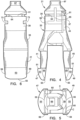
FIGURE 4 is a front view of the holder- inserter shown inFigure 2 . -
FIGURE 5 is a bottom view of the holder- inserter shown inFigure 4 . -
FIGURE 6 is a left side view of the holder- inserter shown inFigure 4 . -
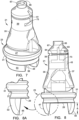
FIGURE 7 is a perspective view of an assembly of the holder- inserter shown inFigure 2 with a mechanical heart valve engaged thereon. -
FIGURE 8 is a front view of the assembly shown inFigure 7 . -
FIGURE 8 A is a fragmentary enlarged view ofFigure 8 . -
FIGURE 9 is a side view of the assembly shown inFigure 7 . -
FIGURE 10 is a fragmentary view similar toFigure 8A showing an alternative embodiment of a heart valve holder-inserter embodying various features of the invention assembled with theFigure 3 heart valve. -
FIGURE 11 is a fragmentary left side view of the assembly shown inFigure 10 . -
FIGURE 12 is a perspective view of an assembly of an alternative embodiment of a holder-inserter shown with a valve similar to that sold by St. Jude Medical, Inc. carried thereon. -
FIGURE 13 is a perspective view of the assembly shown inFIGURE 12 from another angle. -
FIGURE 14 is a front view of the assembly shown inFIGURE 12 . -
FIGURE 15 is a side view of the assembly shown inFIGURE 14 . - The invention provides a
device 21 which serves as a holder- inserter for implanting a mechanical heart valve prosthesis in an annulus in the human heart. The principles embodied in thedevice 21 are effective in creating a useful holder- inserter suited for implanting a wide variety of mechanical heart valves, particularly bileaflet heart valves; however, the preferred embodiment of the device that is shown in the drawings is proportioned and shaped to facilitate the implantation of the On-X heart valve 23, a cross-sectional view of which is illustrated inFIGURE 3 . Thisvalve 23 employs a pair ofleaflets 25 that are pivotally mounted on a valve body ororifice ring 27, as described in detail in the earlier mentioned US patents, whichvalve body 27 has an outwardlyflaring entrance end 29. The illustratedvalve 23 is designed to be inserted as an aortic valve replacement where it will be positioned so that the concave, generally toroidal exterior surface of thecurved entrance end 29 lies in contact with the tissue annulus from which leaflets of the defective natural valve were excised. The implanted prosthesis is secured in place by suturing through asewing ring 31 which is affixed to a
central exterior region of thevalve body 27, with sutures being secured by pledgets which are positioned on the heart side of the annulus, i.e. facing the left ventricle of the heart. - The holder-
inserter device 21 has amain body 33 which comprises two hinged parts that are movable relative to each other. These are arbitrarily referred to as afront part 35 and arear part 37. The body can be made of any acceptable material as well known in this art, but will usually be molded from polymeric material capable of being sterilized, such as nylon, Teflon, Delrin or polysulfone. The twoparts FIGURE 4 ) is formed with anupper section 39 and a dependingleg 41. The rear orright hand part 37 is formed with anupper section 43 and a dependingleg 45. The twolegs valve body 27 to be carried thereupon. - The
main body 33 is molded as two separate pieces with a hinge point therebetween which is established in any suitable manner. For example, a separate hinge pin can be seated in bores provided in bothparts FIGURES 2 and4 ) and a release orientation ( such as that shown in theFIGURE 1 ) wherein oneleg 45 has swung closer to theother leg 41 so as to release a mechanical heart valve with which it was earlier engaged. - The heart valve holder-
inserter 21 generally resembles the prior art device depicted inFIGURE 1 except for the incorporation of a pair ofsloping guide members legs flange 51 formed at its upper end against which the leadingedge 29 of the mechanical heart valve seats; this engagement secures the valve in place on the holder-inserter 21 when the twobody parts FIGURE 4 andFIGURE 7 , for example. - The
guide member 49 is formed with a slopingexterior surface 53 that smoothly extends from the outer edge of theflange 51 down to atip 55. When the twolegs transverse surface 51 lies close to the outer edge of therim 29 of the heart valve, as best seen perhaps inFIGURE 8 where theinserter 21 is illustrated with aheart valve 23 engaged thereon. Thelongitudinally sloping surface 53 extends smoothly over the entire distance from the edge of the ledge to the lower orbottom tip 55, which is described as being a continuous curve, i.e. having no reentrant section. InFIGURE 8 , the outer edges of thetips 55 are spaced apart at their greatest distance, a distance which is substantially less than the diameter of therim 29 of the heart valve at its leading edge, preferably a distance between about 30% and 80% of the diameter of the rim and more preferably between about 50% and 65% of the diameter of the rim. Preferably these outer edges are arcs which lie on a circle which has its center on the longitudinal axis of theinserter 21; however, such is not a requirement as explained hereinafter. - Basically the exterior surface of the
guide members FIGURES 2 and4-9 ; however it may be curved only in the plane perpendicular to longitudinal axis, as shown inFIGURES 10 and 11 where thesurface 83 is a section of a cone. The exterior surfaces 53, which are preferably double-curved as illustrated inFIGURE 4 , are more preferably sections of a surface of revolution. They may be sections of a sphere or of an ovoid or any generally similar shape which might be referred to as spheroidal or ovoidal. By ovoidal is meant ellipsoidal, paraboloidal or the like, with ellipsoidal being most preferred. Although from the standpoint of symmetry it is preferable that bothguide members surfaces 53 which are sections of the same surface of revolution, it should be understood that the guide members, when they are in the ultimate engaging orientation shown inFIGURE 8 , may not lie precisely on the same surface of revolution because their orientation may be somewhat askew with regard to each other, e.g. because of tolerances or other such factors. - As best seen in
FIGURE 5 , at the upper ends of the guide members where theflanges 51 are located, their circular outer edges should subtend an arc of at least about 60° and more preferably an arc between about 75° and about 105°. The upper size limitation on the arc is determined by the amount of clearance which exists in the heart valve to be implanted, because as apparent fromFIGURE 3 , the guide members need to pass between theleaflets 25 and the interior wall of thevalve body 27. An arc of at least about 60° at the upper regions is felt to be sufficient to adequately spread the tissue orifice to facilitate the easy entry of the valve into position.Hollows 58 in the interior surfaces (FIGURE 2 ) also provide clearance for the leaflets. - Side edge surfaces 59 of the
guide members FIGURES 5, 6 and7 , are not longitudinal but are canted; they are preferably canted at a slight angle of at least about 5° and preferably at least about 10°. Thus, as can be seen fromFIGURES 5 and 6 , although the respective side surfaces 59 of theguide members FIGURES 5 and 6 by the reference numeral 59) more easily enter the annulus because of this about 5°-10° offset; moreover, thesesurfaces 59 exert an outward camming action with regard to both the tissue and any pledglets being used to retain sutures on the heart side of the orifice when the holder-inserter carrying the heart valve is rotated after it has been inserted sufficiently into the excised orifice so that the guide members are in contact with the tissue. - The longitudinal length of the guide members is also considered to be important so that further insertion of the guide members, after contact with the tissue is made, exerts a relatively slow and smooth outward deflection of the tissue. In this respect, it is preferred that the longitudinal length of the guide members, i.e., the distance A in
FIGURE 8 , should be between about 20% and about 80% of the diameter of the leading portion of the valve body, more preferably between about 30% and about 40% of the diameter of the valve body circular rim. The longer the length of the guide member, the more gradual may be the radius of curvature of the exterior surfaces which in turn results in a smoother spreading of the annulus. When the valve is close to being in its fully inserted position, it is normal that the inserter be rotated, and it is during this rotation that the side edge surfaces 59 cam outward regions of the tissue annulus that were not initially in contact with a guide member exterior surface. - It can also be seen from
FIGURE 5 that the edge from one corner C (FIGURES 2 and5 ) of a tip to the opposite corner C would be an arc of slightly less than the arc at the upper edge of the surface at the edge of theflange 51 as a result of the canting of the side surfaces 59. Moreover, to avoid a sharp edge at the distal end, the tip ends of the guide members are flattened creating narrowflat surfaces 60. The interior surfaces of the guide members, which are recessed to provide thehollows 58 facing each other, further avoid interference with the leaflets of the bileaflet valve. - When the holder-
inserter 21 is in engagement orientation with abileaflet heart valve 23, as depicted inFIGURE 7 , theupper sections annular groove 61 about the periphery wherein a flexibletensile member 63 is routed and tied to lock them in this abutting position. Thetensile member 63, usually a short length of suture cord, is preferably threaded through atransverse bore 64 in theupper section 39 and knotted.FIGURE 4 shows alongitudinally extending slot 65 which facilitates the surgeon cutting thetensile member 63 to release the engagement and permit the removal of the holder-inserter after theheart valve 23 has been implanted and at least preliminarily sutured into the desired orientation in the wall of the heart. - The
front portion 35 of the main body also includes acap section 67 wherein atop cavity 69 is formed that may extend completely through the body (as indicated inFIGURE 5 ). The upper end of thecavity 69 is shaped so as to interengage with a cooperating member formed at the distal end of a handle (not shown) as well known in this art. The holder-inserter 21 is designed such that it would be commonly packaged together with the heart valve and sterilized prior to shipment to a hospital or other facility. When ready for use, the package would be opened in the operating room, and a sterilized handle would be mated with the assembly via thecavity 69 at the upper end of the holder-inserter once the operation is ready to begin, or later when the surgeon has selected the precise size of heart valve to be implanted. During shipment, the assembly is stably supported in packaging by a C-shaped clip that is received in the pair ofside slots 73 provided in the main body, as best seen in perhapsFIGURE 9 and as generally known in this art. - After the leaflets of the defective natural valve have been excised by operating through the aorta, sutures are placed about the annulus, sometimes with supporting pledglets disposed on the left ventricle side of the annulus, and spaced around the circumference thereof. The surgeon would then insert the holder-
inserter 21 with the engagedvalve 23 so that theguide members surfaces 53 to engage the edge of the tissue annulus, causing it to be smoothly and slowly expanded outward and guiding entry of the leading edge of the valve body into the orifice. The surgeon then rotates the device to smoothly spread the remaining circumference of the tissue annulus outward in arcuate locations where it was not initially in contact, to align the bileaflet valve as desired with respect to the left ventricle. The rotation causes the side edges surfaces 59 not only to cam the tissue outward, but also to engage edges of any pledglets that might be located there to displace them so they will not possibly lie between the valve body exterior surface and the raw edge of the tissue. An appropriate corner blend (not shown) between thesurfaces heart valve 23 is moved smoothly into its desired orientation with the raw edge of the tissue annulus lying in abutment against the concave, generally toroidal exterior surface of the leadingedge 29 of theheart valve 23. At this time, the surgeon sutures the valve at least partially in place using curved suture needles which are passed through thesewing ring 31 and then tied off, as well known in this art. The surgeon can then cut thetensile member 63 where it passes over the cuttingslot 65 so as to release the engagement at the upper end of the main body; this allows theleg 45 at the bottom of therear part 37 to pivot freely and disengage from its contact with the interior surface of the valve body. Slight movement of the inserter to the right inFIGURE 8 disengages theleg 41 from its contact; this allows the holder-inserter to be withdrawn straight away, carrying with it the cutflexible member 65 which is retained in the transverse bore 64 in the cap section. - Depicted in
FIGURES 10 and 11 is an alternative embodiment of a holder-inserter wherein, instead of using guide members that have the double curved exterior surfaces, smooth sloping surfaces are provided by forming each of theguide members 81 withsurface 83 which is a section of a cone. Except for this change, theguide members 81 resemble theguide members bottom tips 85 which have outer edges that are similarly spaced apart and oriented as described above. - Illustrated in
FIGURES 12-15 is an alternative embodiment of a holder-inserter 121 which is designed to support a different mechanical heart valve; it is shown as carrying a mechanical heart valve of the general type as has been sold for several decades by St. Jude Medical, Inc. The components of the holder-inserter 121 are given reference numerals the same as the holder-inserter 21 plus 100. Accordingly, it should be understood that statements made earlier with respect to such a corresponding part are equally applicable to the part bearing the corresponding reference numeral inFIGURES. 12-15 . - This alternative embodiment of the
device 121 that is shown is proportioned and shaped to facilitate the implantation of amechanical heart valve 123, similar to that which is marketed by St. Jude Medical, Inc. and shown inU.S. Patent No. 4,276,658 . Thisvalve 123 likewise employs a pair ofleaflets 125 that are pivotally mounted on a valve body ororifice ring 127. The illustratedvalve 123 is designed to be inserted as an aortic valve replacement where it will be positioned so that a pair ofsemicircular extensions 128 at its entrance end protrude toward the left ventricle in the annulus from which leaflets of the defective natural valve were excised. The implanted prosthesis is secured in place by suturing through asewing ring 131 which is affixed to a central exterior region of thevalve body 127, with sutures being secured by pledgets which are positioned on the heart side of the annulus, i.e. facing the left ventricle of the heart. - The holder-
inserter device 121 has amain body 133 which comprises two hinged, relatively movable parts, afront part 135 and arear part 137. The front or left hand part 135 (as oriented inFIGURE 14 ) is formed with anupper section 139 and a dependingleg 141. The rear orright hand part 137 is formed with anupper section 143 and a dependingleg 145. The twolegs sloping guide members flange 151 formed at its upper end against which the entrance end 129 of the valve seats, in the groove provided in thelegs inserter 121 when the twobody parts - A sloping
exterior surface 153 of theguide member 147 smoothly extends from the outer edge of theflange 151 down to atip 155. When the twolegs transverse surface 151 lies close to the outer edge of the rim of the heart valve entrance end 129. Thelongitudinally sloping surface 153 extends smoothly as a continuous curve over the entire distance from the edge of the ledge to the lower orbottom tip 155. As best seen inFIGURE 14 , the outer edges of thetips 155 are again spaced apart at a distance which is substantially less than the outer diameter of the rim 129 of the heart valve. - The upper ends of the guide members where the
flanges 151 are located have circular outer edges that again each subtend an arc of about 75° and about 105°.Hollows 158 in the interior surfaces also provide clearance for the leaflets. - Side edge surfaces 159 of the
guide members FIGURE 12 , should be between about 20% and about 80% of the diameter of the leading edge of thevalve body 127, more preferably between about 30% and about 40% of the diameter of the outer circular rim surface of thevalve body 127. - The remainder of the construction of the holder-
inserter 121, primarily the upper portion thereof, is the same as that hereinbefore described for the holder-inserter 21. Thebileaflet heart valve 123 would be installed and released in the manner described hereinbefore. Similarly, the surgeon would insert the holder-inserter 121 with thevalve 123 carried thereon so that thesloping guide members surfaces 153 would cause the edges of the tissue annulus to be smoothly and slowly expanded outward, guiding the entry of the leading edge of thevalve body 127 into the orifice. Then, the surgeon would rotate the device to smoothly spread the remaining circumference of the tissue annulus outward, and to align the bileaflet valve as desired with respect to the left ventricle. Once the desired, correct orientation has been attained, the surgeon would suture the valve at least partially in place and then, as earlier described, cut a tensile member to release the engagement at the upper end of the main body of the two portions of the holder- inserter, allowing theleg 145 at the bottom of therear part 137 to pivot freely and disengage so that the holder-inserter 121 can be withdrawn straightaway. - Thus, it should be appreciated that a holder- inserter for a mechanical heart valve prosthesis has been provided that fully meets the objectives stated above. However, although preferred embodiments have been illustrated and described, which constitute the best mode presently known to the inventors for carrying out this invention, it should be appreciated that various changes and modification as would be obvious to one having the ordinary skill in this art may be made without departing from the scope of the invention which is defined in the claims appended hereto. In this respect, although the description has been directed to the implantation of an aortic heart valve, it should be understood that similar advantages are obtained when the holder-inserter is used to insert a valve in the mitral position, for example.
Claims (8)
- A device (21, 121) for inserting a mechanical, surgically implantable prosthetic heart valve into an annulus of a heart of a patient, which device comprises:a main body (33, 133) proportioned for releasable engagement with the valve,said main body having means (69) for connection to a handle for moving and positioning the main body and the valve engaged therewith; andsaid main body also having two sloping guide members (47, 49, 81, 147, 149) extending longitudinally from said main body in a distal direction generally opposite that in which said handle extends, which guide members have tips (55, 155) which are diametrically spaced apart a distance less than a diameter of an outer edge of a distal rim of the valve that would be releasably carried thereon, with outward-facing surfaces (53, 83, 153) of said guide members sloping from said tips outward to about the diameter of the outer edge of the distal rim, whereby passage of the outer edge of distal rim into an annulus, from which the patient's defective valve leaflets have been excised, is facilitated,wherein said main body has a longitudinal axis that substantially coincides with a longitudinal axis of the valve and wherein said outward-facing surfaces (53, 83, 153) are smoothly curved in a plane perpendicular to said longitudinal axis, andwherein said guide member outward-facing surfaces (53, 153) are also curved in a plane parallel to said longitudinal axis, and are sections of a surface of revolution, such as a sphere, an ovoid, or an ellipsoid.
- A device (21, 121) for inserting a mechanical, surgically implantable prosthetic heart valve into an annulus of a heart of a patient, which device comprises:a main body (33, 133) proportioned for releasable engagement with the valve,said main body having means (69) for connection to a handle for moving and positioning the main body and the valve engaged therewith; andsaid main body also having two sloping guide members (47, 49, 81, 147, 149) extending longitudinally from said main body in a distal direction generally opposite that in which said handle extends, which guide members have tips (55, 155) which are diametrically spaced apart a distance less than a diameter of an outer edge of a distal rim of the valve that would be releasably carried thereon, with outward-facing surfaces (53, 83, 153) of said guide members sloping from said tips outward to about the diameter of the outer edge of the distal rim , whereby passage of the outer edge of the distal rim into an annulus, from which the patient's defective valve leaflets have been excised, is facilitatedwherein said main body has a longitudinal axis that substantially coincides with a longitudinal axis of the valve and wherein said outward-facing surfaces (53, 83, 153) are smoothly curved in a plane perpendicular to said longitudinal axis, andwherein said outer edge of the distal rim is substantially circular in cross-section, and wherein said guide member tips (55, 155) terminate in generally circular distal most edges, which edges are arcs of a circle of a diameter between about 30% and about 80% of the diameter of the outer edge of the distal rim.
- The device of claim 2 wherein said guide member outward-facing surfaces are sections of a surface of revolution, such as a cone (83).
- The device of claim 2 or 3 wherein said guide members have a longitudinal length equal to between about 20% and about 80% of the diameter of the outer edge of the distal rim.
- The device of claim 4 wherein said guide members are configured to extend past the distal rim when the valve is carried on said main body for a distance at least equal to about 35% of the diameter of the outer edge of the distal rim.
- The device of any one of claims 1 to 5 for use in implanting the valve that includes a substantially rigid valve body having an exterior surface of generally circular cross-section at its outer edge of the distal rim, which constitutes an entrance end of the valve, with an exterior surface of said valve body curving inward toward an exit end of the valve.
- The device of clam 6 wherein the entrance end of the valve is designed to fit through and be located within an excised orifice of the patient, wherein said tips (55, 155) are spaced diametrically apart a distance between about 30% and 80% of the diameter of the outer edge of the distal rim , and wherein said outward-facing surfaces (53, 83, 153) of said guide members smoothly longitudinally taper outward from said tips to locations spaced apart a distance about equal to or slightly greater than the diameter of the outer edge of the distal rim.
- The device of any one of claims 1 to 7 wherein said main body comprises two hinged parts (35, 37, 135, 137) with one of said guide members constituting a lower section of each of the parts of said main body and wherein the guide members are configured such that pivoting of one of said parts relative to the other causes one guide member to be moved toward the other to release the valve releasably carried thereon, which release is effected once insertion of the valve into the excised orifice is completed.
Applications Claiming Priority (2)
| Application Number | Priority Date | Filing Date | Title |
|---|---|---|---|
| US65077805P | 2005-01-27 | 2005-01-27 | |
| PCT/US2006/002363 WO2006081213A1 (en) | 2005-01-27 | 2006-01-23 | Heart valve inserter |
Publications (3)
| Publication Number | Publication Date |
|---|---|
| EP1845900A1 EP1845900A1 (en) | 2007-10-24 |
| EP1845900A4 EP1845900A4 (en) | 2017-02-08 |
| EP1845900B1 true EP1845900B1 (en) | 2024-12-18 |
Family
ID=36740845
Family Applications (1)
| Application Number | Title | Priority Date | Filing Date |
|---|---|---|---|
| EP06719286.4A Expired - Lifetime EP1845900B1 (en) | 2005-01-27 | 2006-01-23 | Heart valve inserter |
Country Status (4)
| Country | Link |
|---|---|
| US (1) | US8303652B2 (en) |
| EP (1) | EP1845900B1 (en) |
| JP (1) | JP2008528185A (en) |
| WO (1) | WO2006081213A1 (en) |
Families Citing this family (6)
| Publication number | Priority date | Publication date | Assignee | Title |
|---|---|---|---|---|
| JP5591120B2 (en) * | 2008-01-16 | 2014-09-17 | セント ジュード メディカル インコーポレイテッド | Collapsible / expandable prosthetic heart valve delivery and retrieval system |
| WO2009140007A2 (en) * | 2008-04-14 | 2009-11-19 | Ats Medical, Inc. | Tool for implantation of replacement heart valve |
| US20110022165A1 (en) | 2009-07-23 | 2011-01-27 | Edwards Lifesciences Corporation | Introducer for prosthetic heart valve |
| EP2470121B1 (en) * | 2009-08-28 | 2021-03-17 | 3F Therapeutics, Inc. | Surgical delivery device and method of use |
| US9358109B2 (en) * | 2010-01-13 | 2016-06-07 | Vinay Badhwar | Transcorporeal delivery system and method |
| US20140031923A1 (en) * | 2012-07-25 | 2014-01-30 | Medtronic Vascular Galway Limited | Trans-Aortic Surgical Syringe-Type Device for Deployment of a Prosthetic Valve |
Family Cites Families (16)
| Publication number | Priority date | Publication date | Assignee | Title |
|---|---|---|---|---|
| US3491757A (en) * | 1966-12-30 | 1970-01-27 | Raul Olvera Arce | Hypodermic syringe with non-turning tip connector |
| US4585453A (en) * | 1983-02-22 | 1986-04-29 | Shiley, Incorporated | Disposable holder for prosthetic heart valve |
| US4683883A (en) * | 1985-04-30 | 1987-08-04 | Hemex Scientific, Inc. | Two-piece heart valve holder/rotator |
| SU1690738A1 (en) * | 1989-04-11 | 1991-11-15 | Предприятие П/Я Р-6525 | Holder of artificial cardiac valve |
| US5236540A (en) | 1992-04-20 | 1993-08-17 | Gi Shi | Taping device |
| US5236450A (en) * | 1992-06-04 | 1993-08-17 | Carbon Implants, Inc. | Heart valve holder-rotator |
| US5972030A (en) * | 1993-02-22 | 1999-10-26 | Heartport, Inc. | Less-invasive devices and methods for treatment of cardiac valves |
| US5443502A (en) | 1994-06-02 | 1995-08-22 | Carbomedics, Inc. | Rotatable heart valve holder |
| US5641324A (en) | 1995-05-16 | 1997-06-24 | Medical Carbon Research Institute, Llc | Prosthetic heart valve |
| US5545216A (en) | 1995-05-16 | 1996-08-13 | Medical Carbon Research Institute, Llc | Prosthetic heart valve |
| US5772694A (en) | 1995-05-16 | 1998-06-30 | Medical Carbon Research Institute L.L.C. | Prosthetic heart valve with improved blood flow |
| US5984959A (en) * | 1997-09-19 | 1999-11-16 | United States Surgical | Heart valve replacement tools and procedures |
| US6558418B2 (en) * | 1999-01-26 | 2003-05-06 | Edwards Lifesciences Corporation | Flexible heart valve |
| US6287339B1 (en) * | 1999-05-27 | 2001-09-11 | Sulzer Carbomedics Inc. | Sutureless heart valve prosthesis |
| US6319280B1 (en) * | 1999-08-03 | 2001-11-20 | St. Jude Medical, Inc. | Prosthetic ring holder |
| US6859965B1 (en) | 2003-09-15 | 2005-03-01 | Cynthia R. Gourd | Tension relieving apparatus for arms and neck |
-
2006
- 2006-01-23 US US11/568,259 patent/US8303652B2/en active Active
- 2006-01-23 JP JP2007553164A patent/JP2008528185A/en active Pending
- 2006-01-23 EP EP06719286.4A patent/EP1845900B1/en not_active Expired - Lifetime
- 2006-01-23 WO PCT/US2006/002363 patent/WO2006081213A1/en not_active Ceased
Also Published As
| Publication number | Publication date |
|---|---|
| EP1845900A1 (en) | 2007-10-24 |
| EP1845900A4 (en) | 2017-02-08 |
| US20070219629A1 (en) | 2007-09-20 |
| JP2008528185A (en) | 2008-07-31 |
| WO2006081213A1 (en) | 2006-08-03 |
| US8303652B2 (en) | 2012-11-06 |
Similar Documents
| Publication | Publication Date | Title |
|---|---|---|
| US11839542B2 (en) | Ergonomic methods of delivering mitral heart valves | |
| US5476510A (en) | Holder for heart valve | |
| US11464633B2 (en) | Heart valve implants with side slits | |
| US5480425A (en) | Integrated heart valve rotator and holder | |
| EP0852481B1 (en) | Holder for a heart valve prosthesis | |
| US6319280B1 (en) | Prosthetic ring holder | |
| EP1723935A1 (en) | Prosthetic heart valve system | |
| JP2010017580A (en) | Valve replacement instrument | |
| JP2022507421A (en) | Artificial heart valve with commissure support element | |
| JPH06509489A (en) | Flexible suture guide and holder | |
| US8303652B2 (en) | Heart valve inserter | |
| US12029651B2 (en) | Implant holder assembly with actuator for heart valve repair and replacement | |
| JP7146064B2 (en) | Tiltable tool for heart valve prosthesis | |
| CN121925236A (en) | Detachable annuloplasty holder for an annuloplasty ring |
Legal Events
| Date | Code | Title | Description |
|---|---|---|---|
| PUAI | Public reference made under article 153(3) epc to a published international application that has entered the european phase |
Free format text: ORIGINAL CODE: 0009012 |
|
| 17P | Request for examination filed |
Effective date: 20070808 |
|
| AK | Designated contracting states |
Kind code of ref document: A1 Designated state(s): AT BE BG CH CY CZ DE DK EE ES FI FR GB GR HU IE IS IT LI LT LU LV MC NL PL PT RO SE SI SK TR |
|
| DAX | Request for extension of the european patent (deleted) | ||
| RA4 | Supplementary search report drawn up and despatched (corrected) |
Effective date: 20170111 |
|
| RIC1 | Information provided on ipc code assigned before grant |
Ipc: A61F 2/24 20060101AFI20170104BHEP |
|
| STAA | Information on the status of an ep patent application or granted ep patent |
Free format text: STATUS: EXAMINATION IS IN PROGRESS |
|
| 17Q | First examination report despatched |
Effective date: 20210518 |
|
| GRAP | Despatch of communication of intention to grant a patent |
Free format text: ORIGINAL CODE: EPIDOSNIGR1 |
|
| STAA | Information on the status of an ep patent application or granted ep patent |
Free format text: STATUS: GRANT OF PATENT IS INTENDED |
|
| INTG | Intention to grant announced |
Effective date: 20240709 |
|
| RAP3 | Party data changed (applicant data changed or rights of an application transferred) |
Owner name: VALVE SPECIAL PURPOSE CO., LLC |
|
| GRAS | Grant fee paid |
Free format text: ORIGINAL CODE: EPIDOSNIGR3 |
|
| GRAA | (expected) grant |
Free format text: ORIGINAL CODE: 0009210 |
|
| STAA | Information on the status of an ep patent application or granted ep patent |
Free format text: STATUS: THE PATENT HAS BEEN GRANTED |
|
| REG | Reference to a national code |
Ref country code: DE Ref legal event code: R081 Ref document number: 602006060635 Country of ref document: DE Owner name: VALVE SPECIAL PURPOSE CO., LLC, AUSTIN, US Free format text: FORMER OWNER: VALVE SPECIAL PURPOSE CO., LLC., AUSTIN, TEX., US |
|
| AK | Designated contracting states |
Kind code of ref document: B1 Designated state(s): AT BE BG CH CY CZ DE DK EE ES FI FR GB GR HU IE IS IT LI LT LU LV MC NL PL PT RO SE SI SK TR |
|
| P01 | Opt-out of the competence of the unified patent court (upc) registered |
Free format text: CASE NUMBER: APP_60645/2024 Effective date: 20241111 |
|
| REG | Reference to a national code |
Ref country code: GB Ref legal event code: FG4D |
|
| REG | Reference to a national code |
Ref country code: CH Ref legal event code: EP |
|
| REG | Reference to a national code |
Ref country code: DE Ref legal event code: R096 Ref document number: 602006060635 Country of ref document: DE |
|
| REG | Reference to a national code |
Ref country code: IE Ref legal event code: FG4D |
|
| REG | Reference to a national code |
Ref country code: LT Ref legal event code: MG9D |
|
| PGFP | Annual fee paid to national office [announced via postgrant information from national office to epo] |
Ref country code: DE Payment date: 20250218 Year of fee payment: 20 |
|
| PG25 | Lapsed in a contracting state [announced via postgrant information from national office to epo] |
Ref country code: FI Free format text: LAPSE BECAUSE OF FAILURE TO SUBMIT A TRANSLATION OF THE DESCRIPTION OR TO PAY THE FEE WITHIN THE PRESCRIBED TIME-LIMIT Effective date: 20241218 |
|
| PG25 | Lapsed in a contracting state [announced via postgrant information from national office to epo] |
Ref country code: BG Free format text: LAPSE BECAUSE OF FAILURE TO SUBMIT A TRANSLATION OF THE DESCRIPTION OR TO PAY THE FEE WITHIN THE PRESCRIBED TIME-LIMIT Effective date: 20241218 |
|
| REG | Reference to a national code |
Ref country code: NL Ref legal event code: MP Effective date: 20241218 |
|
| PG25 | Lapsed in a contracting state [announced via postgrant information from national office to epo] |
Ref country code: LV Free format text: LAPSE BECAUSE OF FAILURE TO SUBMIT A TRANSLATION OF THE DESCRIPTION OR TO PAY THE FEE WITHIN THE PRESCRIBED TIME-LIMIT Effective date: 20241218 Ref country code: GR Free format text: LAPSE BECAUSE OF FAILURE TO SUBMIT A TRANSLATION OF THE DESCRIPTION OR TO PAY THE FEE WITHIN THE PRESCRIBED TIME-LIMIT Effective date: 20250319 |
|
| PG25 | Lapsed in a contracting state [announced via postgrant information from national office to epo] |
Ref country code: NL Free format text: LAPSE BECAUSE OF FAILURE TO SUBMIT A TRANSLATION OF THE DESCRIPTION OR TO PAY THE FEE WITHIN THE PRESCRIBED TIME-LIMIT Effective date: 20241218 |
|
| REG | Reference to a national code |
Ref country code: AT Ref legal event code: MK05 Ref document number: 1751614 Country of ref document: AT Kind code of ref document: T Effective date: 20241218 |
|
| PG25 | Lapsed in a contracting state [announced via postgrant information from national office to epo] |
Ref country code: PL Free format text: LAPSE BECAUSE OF FAILURE TO SUBMIT A TRANSLATION OF THE DESCRIPTION OR TO PAY THE FEE WITHIN THE PRESCRIBED TIME-LIMIT Effective date: 20241218 |
|
| PG25 | Lapsed in a contracting state [announced via postgrant information from national office to epo] |
Ref country code: ES Free format text: LAPSE BECAUSE OF FAILURE TO SUBMIT A TRANSLATION OF THE DESCRIPTION OR TO PAY THE FEE WITHIN THE PRESCRIBED TIME-LIMIT Effective date: 20241218 |
|
| PG25 | Lapsed in a contracting state [announced via postgrant information from national office to epo] |
Ref country code: IS Free format text: LAPSE BECAUSE OF FAILURE TO SUBMIT A TRANSLATION OF THE DESCRIPTION OR TO PAY THE FEE WITHIN THE PRESCRIBED TIME-LIMIT Effective date: 20250418 |
|
| PG25 | Lapsed in a contracting state [announced via postgrant information from national office to epo] |
Ref country code: PT Free format text: LAPSE BECAUSE OF FAILURE TO SUBMIT A TRANSLATION OF THE DESCRIPTION OR TO PAY THE FEE WITHIN THE PRESCRIBED TIME-LIMIT Effective date: 20250421 |
|
| PG25 | Lapsed in a contracting state [announced via postgrant information from national office to epo] |
Ref country code: EE Free format text: LAPSE BECAUSE OF FAILURE TO SUBMIT A TRANSLATION OF THE DESCRIPTION OR TO PAY THE FEE WITHIN THE PRESCRIBED TIME-LIMIT Effective date: 20241218 |
|
| PG25 | Lapsed in a contracting state [announced via postgrant information from national office to epo] |
Ref country code: AT Free format text: LAPSE BECAUSE OF FAILURE TO SUBMIT A TRANSLATION OF THE DESCRIPTION OR TO PAY THE FEE WITHIN THE PRESCRIBED TIME-LIMIT Effective date: 20241218 Ref country code: RO Free format text: LAPSE BECAUSE OF FAILURE TO SUBMIT A TRANSLATION OF THE DESCRIPTION OR TO PAY THE FEE WITHIN THE PRESCRIBED TIME-LIMIT Effective date: 20241218 |
|
| PG25 | Lapsed in a contracting state [announced via postgrant information from national office to epo] |
Ref country code: SK Free format text: LAPSE BECAUSE OF FAILURE TO SUBMIT A TRANSLATION OF THE DESCRIPTION OR TO PAY THE FEE WITHIN THE PRESCRIBED TIME-LIMIT Effective date: 20241218 |
|
| PG25 | Lapsed in a contracting state [announced via postgrant information from national office to epo] |
Ref country code: CZ Free format text: LAPSE BECAUSE OF FAILURE TO SUBMIT A TRANSLATION OF THE DESCRIPTION OR TO PAY THE FEE WITHIN THE PRESCRIBED TIME-LIMIT Effective date: 20241218 |
|
| PG25 | Lapsed in a contracting state [announced via postgrant information from national office to epo] |
Ref country code: IT Free format text: LAPSE BECAUSE OF FAILURE TO SUBMIT A TRANSLATION OF THE DESCRIPTION OR TO PAY THE FEE WITHIN THE PRESCRIBED TIME-LIMIT Effective date: 20241218 |
|
| REG | Reference to a national code |
Ref country code: CH Ref legal event code: PL |
|
| PG25 | Lapsed in a contracting state [announced via postgrant information from national office to epo] |
Ref country code: SE Free format text: LAPSE BECAUSE OF FAILURE TO SUBMIT A TRANSLATION OF THE DESCRIPTION OR TO PAY THE FEE WITHIN THE PRESCRIBED TIME-LIMIT Effective date: 20241218 |
|
| PG25 | Lapsed in a contracting state [announced via postgrant information from national office to epo] |
Ref country code: MC Free format text: LAPSE BECAUSE OF FAILURE TO SUBMIT A TRANSLATION OF THE DESCRIPTION OR TO PAY THE FEE WITHIN THE PRESCRIBED TIME-LIMIT Effective date: 20241218 Ref country code: LU Free format text: LAPSE BECAUSE OF NON-PAYMENT OF DUE FEES Effective date: 20250123 |
|
| REG | Reference to a national code |
Ref country code: DE Ref legal event code: R097 Ref document number: 602006060635 Country of ref document: DE |
|
| PG25 | Lapsed in a contracting state [announced via postgrant information from national office to epo] |
Ref country code: DK Free format text: LAPSE BECAUSE OF FAILURE TO SUBMIT A TRANSLATION OF THE DESCRIPTION OR TO PAY THE FEE WITHIN THE PRESCRIBED TIME-LIMIT Effective date: 20241218 |
|
| PG25 | Lapsed in a contracting state [announced via postgrant information from national office to epo] |
Ref country code: BE Free format text: LAPSE BECAUSE OF NON-PAYMENT OF DUE FEES Effective date: 20250131 |
|
| PG25 | Lapsed in a contracting state [announced via postgrant information from national office to epo] |
Ref country code: CH Free format text: LAPSE BECAUSE OF NON-PAYMENT OF DUE FEES Effective date: 20250131 |
|
| REG | Reference to a national code |
Ref country code: BE Ref legal event code: MM Effective date: 20250131 |
|
| PLBE | No opposition filed within time limit |
Free format text: ORIGINAL CODE: 0009261 |
|
| STAA | Information on the status of an ep patent application or granted ep patent |
Free format text: STATUS: NO OPPOSITION FILED WITHIN TIME LIMIT |
|
| 26N | No opposition filed |
Effective date: 20250919 |
|
| GBPC | Gb: european patent ceased through non-payment of renewal fee |
Effective date: 20250318 |
|
| PG25 | Lapsed in a contracting state [announced via postgrant information from national office to epo] |
Ref country code: GB Free format text: LAPSE BECAUSE OF NON-PAYMENT OF DUE FEES Effective date: 20250318 |
|
| PG25 | Lapsed in a contracting state [announced via postgrant information from national office to epo] |
Ref country code: FR Free format text: LAPSE BECAUSE OF NON-PAYMENT OF DUE FEES Effective date: 20250218 |
|
| PG25 | Lapsed in a contracting state [announced via postgrant information from national office to epo] |
Ref country code: IE Free format text: LAPSE BECAUSE OF NON-PAYMENT OF DUE FEES Effective date: 20250123 |
|
| REG | Reference to a national code |
Ref country code: DE Ref legal event code: R071 Ref document number: 602006060635 Country of ref document: DE |
|
| PG25 | Lapsed in a contracting state [announced via postgrant information from national office to epo] |
Ref country code: CY Free format text: LAPSE BECAUSE OF FAILURE TO SUBMIT A TRANSLATION OF THE DESCRIPTION OR TO PAY THE FEE WITHIN THE PRESCRIBED TIME-LIMIT Effective date: 20241218 |
|
| PG25 | Lapsed in a contracting state [announced via postgrant information from national office to epo] |
Ref country code: TR Free format text: LAPSE BECAUSE OF FAILURE TO SUBMIT A TRANSLATION OF THE DESCRIPTION OR TO PAY THE FEE WITHIN THE PRESCRIBED TIME-LIMIT Effective date: 20241218 |
|
| PG25 | Lapsed in a contracting state [announced via postgrant information from national office to epo] |
Ref country code: LT Free format text: LAPSE BECAUSE OF FAILURE TO SUBMIT A TRANSLATION OF THE DESCRIPTION OR TO PAY THE FEE WITHIN THE PRESCRIBED TIME-LIMIT Effective date: 20241218 |