EP1845614A2 - Audio output apparatus and television broadcast receiver - Google Patents
Audio output apparatus and television broadcast receiver Download PDFInfo
- Publication number
- EP1845614A2 EP1845614A2 EP07007101A EP07007101A EP1845614A2 EP 1845614 A2 EP1845614 A2 EP 1845614A2 EP 07007101 A EP07007101 A EP 07007101A EP 07007101 A EP07007101 A EP 07007101A EP 1845614 A2 EP1845614 A2 EP 1845614A2
- Authority
- EP
- European Patent Office
- Prior art keywords
- signal
- audio
- circuit
- protect
- output
- Prior art date
- Legal status (The legal status is an assumption and is not a legal conclusion. Google has not performed a legal analysis and makes no representation as to the accuracy of the status listed.)
- Granted
Links
Images



Classifications
-
- H—ELECTRICITY
- H03—ELECTRONIC CIRCUITRY
- H03G—CONTROL OF AMPLIFICATION
- H03G3/00—Gain control in amplifiers or frequency changers
- H03G3/20—Automatic control
- H03G3/30—Automatic control in amplifiers having semiconductor devices
- H03G3/34—Muting amplifier when no signal is present
- H03G3/348—Muting in response to a mechanical action or to power supply variations, e.g. during tuning; Click removal circuits
Definitions
- the present invention relates to an audio output apparatus and a television broadcast receiver.
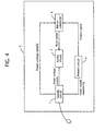
- FIG. 4 shows a schematic block diagram of a conventional audio output apparatus
- FIG. 5 shows a timing chart indicating timing of the muting operation executed in the conventional audio output apparatus.
- the conventional audio output apparatus 5 is substantially made up of a supply circuit 1, audio circuit 2, microcomputer 3, and protect circuit 4.
- the supply circuit 1 receives a supply voltage from an external commercial power supply or the like and generates various voltages based on the supply voltage to supply the voltages to respective components such as the supply circuit 1, audio circuit 2, and microcomputer 3 of the audio output apparatus 5.
- the audio circuit 2 receives an audio signal, applies predetermined audio processing to the audio signal, and outputs the resultant signal to a speaker or the like (not shown).
- the microcomputer 3 is electrically connected with each of the components forming the audio output apparatus 5.
- the CPU as an internal component of the microcomputer 3 controls the entirety of the audio output apparatus 5 in accordance with programs written in the ROM and RAM also being the internal components of the microcomputer 3.
- the protect circuit 4 monitors the output voltage of the supply circuit 1 and outputs a protect signal to the microcomputer 3 when an abnormal increase or decrease in the output voltage occurs.
- the microcomputer 3 Upon receipt of the protect signal, the microcomputer 3 generates a mute signal for muting the audio circuit 2 and outputs it to the audio circuit 2. Since, upon receipt of the mute signal, the audio circuit 2 stops outputting of the audio signal, even if the voltage supply from the power supply circuit then becomes deficient so as to generate an audio signal to cause an audio noise (pop sound), the audio signal to cause the audio noise is not output from the audio circuit 2 to the speaker or the like.
- the present invention discloses an audio output apparatus and a television broadcast receiver capable of positively muting the audio circuit 2 before power supply to the audio circuit 2 is turned off in the event of an abnormality in the supply circuit.
- One aspect of the present invention provides an audio output apparatus for applying signal processing to an audio signal input thereto and outputting the resultant signal to a speaker comprising: a supply circuit for generating various voltages from a supply voltage supplied from outside and outputting the generated voltages; an audio circuit supplied with a supply voltage from said supply circuit performs an audio signal process, and stops the audio output upon receipt of a mute signal; a protect circuit for outputting a protect signal upon detection of an abnormality in said supply circuit; a microcomputer for outputting a mute signal to said audio circuit upon receipt of the protect signal, and said protect circuit, upon detection of the abnormality, turns the protect signal into a mute signal and outputs the mute signal to said audio circuit.
- An optional aspect of the present invention provides an audio output apparatus, wherein the mute signal is set High when an audio is to be output and set Low when the audio is to be muted, and said audio circuit is muted when the signal at Low is input thereto.
- a television broadcast receiver for receiving a television broadcast signal for displaying a video of a video signal based on the television broadcast signal on a screen and outputting an audio of an audio signal based on the television broadcast signal from a speaker, comprising: an audio output apparatus supplied with an audio signal for applying signal processing to the audio signal and outputting a resultant signal to a speaker, said audio output apparatus comprising: a supply circuit supplied with a supply voltage from an external commercial power supply through an AC cord for generating various voltages based on the supply voltage and supplying the voltages to respective components of the television broadcast receiver; an audio circuit amplifying an audio signal input thereto in accordance with a volume control signal of 0 - 5V output from a microcomputer and outputting the audio signal to a speaker when a high voltage signal is input thereto, and stopping the outputting of the audio signal when a mute signal being a low voltage signal is input thereto; a protect circuit coupled with an output line of said supply circuit for outputting a protect signal represented by a low
- FIG. 1 is a block diagram explanatory of a general configuration of a television broadcast receiver 100 according to a present embodiment.
- FIG. 2 is a block diagram explanatory of circuitry for performing a muting operation in a present embodiment.
- FIG. 3 is a timing chart showing timing of a muting operation in a present embodiment.
- FIG. 4 is a schematic block diagram of a conventional audio output apparatus.
- FIG. 5 is a timing chart showing timing of a muting operation in a conventional audio output apparatus.
- FIG. 1 is a block diagram showing a general configuration of the television broadcast receiver 100 of the present embodiment. Incidentally, detailed description and drawings will be omitted of components of the television broadcast receiver 100 that are not directly related with the present invention. While the present embodiment will be explained as applied to a television broadcast receiver as an example of electric/electronic equipment mounting an audio output apparatus thereon, it is not limitative, but it is also applicable to various kinds of electric/electronic equipment such as a stereo or radio that outputs an audio.
- the television broadcast receiver 100 is substantially made up of a tuner 10, chroma IC 12, cathode amplifier 14, CRT 16, audio circuit 18, speaker 20, microcomputer 22, supply circuit 26, protect circuit 24, remote control receiver 28, and remote controller 30.
- the tuner 10 is connectible with an antenna 10a as an input source of a broadcast signal.
- the tuner 10 receives signals of a desired frequency band, selects from the received signals a signal of a required frequency, applies high-frequency-amplification to the selected signal, converts the high frequency signal into an intermediate frequency signal, and outputs the resultant signal.
- the chroma IC 12 generally applies intermediate-frequency amplification to the intermediate-frequency signal input thereto at a suitable gain to thereby perform video detection and audio detection, and, on one hand, applies a predetermined chrominance demodulation to the detected video output and outputs it as an RGB signal and, on the other hand, outputs the detected audio signal as an audio signal.
- the RGB signal is output to the external cathode amplifier 14 and the signal is suitably amplified in the cathode amplifier 14 to be supplied to the CRT 16.
- the audio signal is also fed to the audio circuit 18 external to the chroma IC 12 and suitably amplifier in the audio circuit 18 to be supplied to the speaker 20.
- the mute signal is such a signal that goes High when an audio is to be output and goes Low when the audio is to be muted.
- the audio circuit 18 mutes upon receipt of the Low signal.
- the microcomputer 22 its internal component CPU performs, based on programs written in ROM and RAM being also the internal components of the CPU, the overall control of the television broadcast receiver 100 such us the channel selection control of the tuner 10 and the audio control and mute control of the audio circuit.
- the microcomputer 22 and the above tuner 10 and the chroma IC 12 are connected with a predetermined IIC bus and they are allowed to communicate with each other via the IIC bus. Further, when the microcomputer 22 has received a voltage signal from the remote control receiver 28 and detected a key operation corresponding to the voltage signal, it accepts the operating input from the remote control 30 to perform such control as volume control and mute control of the audio circuit.
- the supply circuit 26 is supplied with a power voltage from an external commercial power supply or the like through an AC cord or the like and generates various voltages based on the power voltage and outputs the voltages. Though it is not shown in FIG. 1, the supply circuit 26 is supplying power voltages to each component of the television broadcast receiver 100.
- the protect circuit 24 is connected to either the output line or the input line of the supply circuit 26 and monitors an abnormality of the current or voltage of the supply circuit 26. Upon detection of an abnormality, it outputs a protect signal to the microcomputer 22.
- the protect circuit 24, for example, is a circuit that is connected to the output line of the supply circuit 26 and outputs a protect signal when the output voltage decreases below a predetermined value.
- a circuit that has a comparator having the output voltage (Va) of the supply circuit 26 and a predetermined reference voltage (Vb) input thereto and is adapted to output different signals depending on the magnitude relationship between the voltages Va and Vb, or a circuit that uses a resistor, switching element, rectifying element, and the like and detects an abnormality of the output voltage in the supply circuit to output the relevant signal, may be considered as the protect circuit 24.
- the microcomputer 22 Upon receipt of a protect signal, the microcomputer 22 outputs a control signal for normally stopping the television broadcast receiver 100 or performs a process to normally stop the control program of the microcomputer 22 itself. More concretely, it performs such control as to mute the audio circuit 18 by outputting a mute signal to the audio circuit 18.
- the remote control receiver 28 upon receipt of a command signal sent from the remote controller 30, generates a corresponding voltage signal.
- the remote controller 30 includes various buttons that are normally used for controlling the television broadcast receiver 100 such as ON/OFF buttons and channel select buttons, not shown, and the volume buttons 30a for controlling the volume up/down and the mute button 30b for the muting.
- FIG. 2 a circuit configuration for performing the muting operation in the present embodiment will be described.
- the figure shows a block diagram of circuits related to the muting operation in the television broadcast receiver 100 and their mutual relationships.
- an audio output apparatus may also be provided only by the same configuration.
- FIG. 2 shows a supply circuit 26, audio circuit 18, microcomputer 22, and protect circuit 24, in which the audio circuit 18 and microcomputer 22 are supplied with power voltages from the supply circuit 26.
- the audio circuit 18, in response to a volume control signal input from the microcomputer 22 ranging 0 to 5V, determines the amplification factor of the audio signal output therefrom. More specifically, the higher the voltage value of the volume control signal, the greater becomes the amplification factor of the output audio signal, and the lower the voltage value of the volume control signal, the smaller becomes the amplification factor; when the voltage value of the volume control signal is 0V, the muting operation is performed.
- a muting control may be executed separately from the volume control. In such case, the signal allowing the audio circuit to output an audio signal may be set High (voltage On) and the signal not allowing it to output an audio signal may be set Low (no voltage) .
- the line through which the microcomputer 22 outputs the mute signal to the audio circuit 18 and the line through which the protect circuit 24 outputs the protect signal to the microcomputer 22 are connected by the diode D1 as shown in FIG. 2.
- the diode D1 is connected such that its anode side is turned toward the line mentioned first above and its cathode side is turned toward the line mentioned second above.
- the protect signal is prevented from entering into the microcomputer 22 and the audio circuit 18 when the supply circuit 26 is normally outputting its output and, thereby, the microcomputer 22 and audio circuit 18 are prevented from making a malfunction.
- a Low (0V) protect signal is output from the protect circuit 24 upon occurrence of an abnormality in the supply circuit 26, the line connecting the microcomputer 22 and the audio circuit 18 is pulled to Low. Therefore, even if a High signal is being output from the microcomputer 22, a Low signal is input to the audio circuit 18 and, thus, the audio circuit 18 is muted regardless of the control of the microcomputer 22.
- the protect signal is output at timing earlier than the occurrence of an audio noise in the audio circuit 18 on account of the voltage supplied to the audio circuit 18 becoming deficient.
- FIG. 3 is a timing chart showing timing of the muting control executed in the present embodiment.
- the protect circuit 24 detects the decrease in the voltage and outputs a protect signal at Low.
- the microcomputer 22 has not yet received the Low protect signal and, therefore, it has not yet output a mute signal (Low) to the audio circuit 18 but is outputting a signal (High) to cause the audio output to be made.
- the audio circuit 18 is outputting the audio output.
- an audio noise occurs in the audio circuit 18 when the voltage supplied from the supply circuit 26 to the audio circuit 18 becomes deficient, an audio signal causing the audio noise is not output from the audio circuit 18 because the audio signal has been muted.
- the protect circuit 24 detects the abnormality and outputs a protect signal to the audio circuit 18. Therefore, the audio circuit 18 having received the protect signal stops its audio output such that an audio noise due to the deficiency of the supplied voltage thereto is not output.
- the microcomputer 22 controls the audio circuit 18 by outputting thereto such signals as to allow the audio circuit 18 to output an audio, or increase the volume of the audio, or to mute the audio.
- the audio output apparatus of the present invention is, in an audio output apparatus for applying signal processing to an audio signal input thereto and outputting the resultant signal to a speaker comprising: a supply circuit for generating various voltages from a supply voltage supplied from outside and outputting the generated voltages; an audio circuit supplied with a supply voltage from said supply circuit performs an audio signal process, and stops the audio output upon receipt of a mute signal; a protect circuit for outputting a protect signal upon detection of an abnormality in said supply circuit; a microcomputer for outputting a mute signal to said audio circuit upon receipt of the protect signal, and said protect circuit, upon detection of the abnormality, turns the protect signal into a mute signal and outputs the mute signal to said audio circuit.
- the protect circuit when an abnormality occurs in the supply circuit and its output decreases, the protect circuit detects the abnormality and outputs a protect signal to the audio circuit.
- the audio circuit upon receipt of the protect signal, stops its audio output, so that an audio noise due to deficiency in the supplied voltage is not output.
- the microcomputer controls the audio circuit by supplying the audio circuit with such a signal as to allow the audio circuit to output an audio, or to increase the audio volume, or with a mute signal.
- the mute signal it is enough if it can mute the above audio circuit and, therefore, various signals may be used as the mute signal.
- it may be a voltage signal of a value greater than a predetermined threshold value, a voltage signal of a value smaller than a predetermined threshold value, a voltage signal of 0V, a combination of a plurality of voltage signals, or a combination of the above mentioned signals.
- protect circuit it is only required that it can detect an abnormality in the supply circuit and output a protect signal, namely, it is enough if it can detect that the output voltage, output current, input voltage, or input current is greatly deviated from the normal value.
- the above protect signal and the mute signal output from the microcomputer are identical signals when input to the audio circuit.
- the present invention configured as described above can provide an audio output apparatus capable of positively muting its audio circuit when an abnormality has occurred in its supply circuit, before the audio circuit is cut off. More specifically, the audio circuit can be muted prior to a muting operation of the audio circuit executed by the microcomputer at such a time as when the AC cord is pulled out of the wall and then the supply voltage to the audio circuit is becoming deficient. Thus, occurrence of such an audio noise as a pop sound can be prevented.
- the mute signal is set High when an audio is to be output, and set Low when the audio is to be muted, and the audio signal is muted when the Low signal is input thereto.
- the muting operation of the audio circuit is achieved by pulling the High signal output from the microcomputer to Low. Hence, it is made possible to mute the audio circuit when an abnormality has occurred therein by the use of a configuration using simple circuits.
- the audio output apparatus is configured in the audio output apparatus such that a line through which the protect signal from said protect circuit is output and a line connecting said microcomputer and said audio circuit are connected by a diode, with a cathode side thereof turned toward the line through which the protect signal is output
- the protect signal is prevented from flowing into the microcomputer or the audio circuit and, hence, there is no possibility that the microcomputer or the audio circuit causes a malfunction.
- a television broadcast receiver for receiving a television broadcast signal for displaying a video of a video signal based on the television broadcast signal on a screen and outputting an audio of an audio signal based on the television broadcast signal from a speaker
- said audio output apparatus comprising: a supply circuit supplied with a supply voltage from an external commercial power supply through an AC cord for generating various voltages based on the supply voltage and supplying the voltages to respective components of the television broadcast receiver; an audio circuit amplifying an audio signal input thereto in accordance with a volume control signal of 0 - 5V output from a microcomputer and outputting the audio signal to a speaker when a high voltage signal is input thereto, and stopping the outputting of the audio signal when a mute signal being a low voltage signal is input thereto; a protect circuit coupled with an output line of said supply circuit for outputting a protect signal represented by a
Landscapes
- Television Receiver Circuits (AREA)
- Amplifiers (AREA)
- Circuits Of Receivers In General (AREA)
Abstract
Description
- The present invention relates to an audio output apparatus and a television broadcast receiver.
- In a conventional electronic apparatus such as a television broadcast receiver provided with an audio output apparatus, a muting operation of the audio circuit has been executed by a personal computer. FIG. 4 shows a schematic block diagram of a conventional audio output apparatus and FIG. 5 shows a timing chart indicating timing of the muting operation executed in the conventional audio output apparatus.
- Referring to FIG. 4, the conventional
audio output apparatus 5 is substantially made up of a supply circuit 1,audio circuit 2,microcomputer 3, and protectcircuit 4.
The supply circuit 1 receives a supply voltage from an external commercial power supply or the like and generates various voltages based on the supply voltage to supply the voltages to respective components such as the supply circuit 1,audio circuit 2, andmicrocomputer 3 of theaudio output apparatus 5. Theaudio circuit 2 receives an audio signal, applies predetermined audio processing to the audio signal, and outputs the resultant signal to a speaker or the like (not shown). - The
microcomputer 3 is electrically connected with each of the components forming theaudio output apparatus 5. The CPU as an internal component of themicrocomputer 3 controls the entirety of theaudio output apparatus 5 in accordance with programs written in the ROM and RAM also being the internal components of themicrocomputer 3. - The
protect circuit 4 monitors the output voltage of the supply circuit 1 and outputs a protect signal to themicrocomputer 3 when an abnormal increase or decrease in the output voltage occurs. Themicrocomputer 3, upon receipt of the protect signal, outputs a mute signal to theaudio circuit 2 to cause theaudio circuit 2 to stop outputting of the audio signal to the speaker or the like. - Operations performed in the
audio output apparatus 5 during the period from when the power supply voltage to the supply circuit 1 is stopped to when the outputting of the audio signal from theaudio circuit 2 is stopped will be described with reference to the timing chart of FIG. 5. When the power supply to the supply circuit 1 is stopped on account of removal of the AC cord as shown in the drawing, for example, the supply voltage output from the supply circuit 1 gradually decreases and hence theprotect circuit 4 detects the decrease and outputs a protect signal. - Upon receipt of the protect signal, the
microcomputer 3 generates a mute signal for muting theaudio circuit 2 and outputs it to theaudio circuit 2. Since, upon receipt of the mute signal, theaudio circuit 2 stops outputting of the audio signal, even if the voltage supply from the power supply circuit then becomes deficient so as to generate an audio signal to cause an audio noise (pop sound), the audio signal to cause the audio noise is not output from theaudio circuit 2 to the speaker or the like. - Configurations similar to the above apparatus that is controlled by a microcomputer so as to mute the audio signal when the supply of power voltage has been abruptly stopped are disclosed in
Japanese Unexamined Patent Application Publication Nos. H4 -220093 S63-236485 H4-217818 - When the conventional method as described above was carried out, however, it sometimes occurred that the power supply from the supply circuit 1 to the
audio circuit 2 became deficient before themicrocomputer 3 output the mute signal. Therefore, sometimes theaudio circuit 2 was turned off before the mute signal from themicrocomputer 3 arrived at theaudio circuit 2. Hence, there was a possibility that an audio noise was output to the speaker or the like. - The present invention discloses an audio output apparatus and a television broadcast receiver capable of positively muting the
audio circuit 2 before power supply to theaudio circuit 2 is turned off in the event of an abnormality in the supply circuit. - One aspect of the present invention provides an audio output apparatus for applying signal processing to an audio signal input thereto and outputting the resultant signal to a speaker comprising: a supply circuit for generating various voltages from a supply voltage supplied from outside and outputting the generated voltages; an audio circuit supplied with a supply voltage from said supply circuit performs an audio signal process, and stops the audio output upon receipt of a mute signal; a protect circuit for outputting a protect signal upon detection of an abnormality in said supply circuit; a microcomputer for outputting a mute signal to said audio circuit upon receipt of the protect signal, and said protect circuit, upon detection of the abnormality, turns the protect signal into a mute signal and outputs the mute signal to said audio circuit.
- An optional aspect of the present invention provides an audio output apparatus, wherein the mute signal is set High when an audio is to be output and set Low when the audio is to be muted, and said audio circuit is muted when the signal at Low is input thereto.
- Another aspect of the present invention provides A television broadcast receiver for receiving a television broadcast signal for displaying a video of a video signal based on the television broadcast signal on a screen and outputting an audio of an audio signal based on the television broadcast signal from a speaker, comprising: an audio output apparatus supplied with an audio signal for applying signal processing to the audio signal and outputting a resultant signal to a speaker, said audio output apparatus comprising: a supply circuit supplied with a supply voltage from an external commercial power supply through an AC cord for generating various voltages based on the supply voltage and supplying the voltages to respective components of the television broadcast receiver; an audio circuit amplifying an audio signal input thereto in accordance with a volume control signal of 0 - 5V output from a microcomputer and outputting the audio signal to a speaker when a high voltage signal is input thereto, and stopping the outputting of the audio signal when a mute signal being a low voltage signal is input thereto; a protect circuit coupled with an output line of said supply circuit for outputting a protect signal represented by a low voltage signal when the output voltage of said supply circuit is decreased below a predetermined value; the microcomputer controlling said audio circuit to amplify the audio signal and outputting, upon receipt of the protect signal from said protect circuit, a mute signal to said audio circuit; and a diode disposed to connect a line through which the protect signal from said protect circuit is output and a line connecting said microcomputer and said audio circuit, such that a cathode side thereof is turned toward the line through which the protect signal is output; when the output voltage of said supply circuit begins to decrease, said protect circuit detects the decrease and outputs the low voltage signal as the protect signal, the line connecting said microcomputer and said audio circuit is pulled to low voltage substantially identical to the level of the protect signal thorough said diode, so that the mute signal being the low voltage signal is input to the audio circuit to mute the audio circuit.
- FIG. 1 is a block diagram explanatory of a general configuration of a
television broadcast receiver 100 according to a present embodiment.
FIG. 2 is a block diagram explanatory of circuitry for performing a muting operation in a present embodiment.
FIG. 3 is a timing chart showing timing of a muting operation in a present embodiment.
FIG. 4 is a schematic block diagram of a conventional audio output apparatus.
FIG. 5 is a timing chart showing timing of a muting operation in a conventional audio output apparatus. - A preferred embodiment of the present invention will be described below in the below mentioned order:
- (1) General configuration of a television broadcast receiver;
- (2) Muting circuit; and
- (3) Summary.
- FIG. 1 is a block diagram showing a general configuration of the
television broadcast receiver 100 of the present embodiment. Incidentally, detailed description and drawings will be omitted of components of thetelevision broadcast receiver 100 that are not directly related with the present invention. While the present embodiment will be explained as applied to a television broadcast receiver as an example of electric/electronic equipment mounting an audio output apparatus thereon, it is not limitative, but it is also applicable to various kinds of electric/electronic equipment such as a stereo or radio that outputs an audio. - Referring to FIG. 1, the
television broadcast receiver 100 is substantially made up of atuner 10, chroma IC 12,cathode amplifier 14, CRT 16,audio circuit 18,speaker 20,microcomputer 22,supply circuit 26,protect circuit 24,remote control receiver 28, andremote controller 30. - The
tuner 10 is connectible with anantenna 10a as an input source of a broadcast signal. Thetuner 10 receives signals of a desired frequency band, selects from the received signals a signal of a required frequency, applies high-frequency-amplification to the selected signal, converts the high frequency signal into an intermediate frequency signal, and outputs the resultant signal. - The
chroma IC 12 generally applies intermediate-frequency amplification to the intermediate-frequency signal input thereto at a suitable gain to thereby perform video detection and audio detection, and, on one hand, applies a predetermined chrominance demodulation to the detected video output and outputs it as an RGB signal and, on the other hand, outputs the detected audio signal as an audio signal. The RGB signal is output to theexternal cathode amplifier 14 and the signal is suitably amplified in thecathode amplifier 14 to be supplied to theCRT 16. Meanwhile, the audio signal is also fed to theaudio circuit 18 external to thechroma IC 12 and suitably amplifier in theaudio circuit 18 to be supplied to thespeaker 20. - The
audio circuit 18, supplied with the power voltage from thesupply circuit 26, performs audio signal processing and, if a mute signal is input thereto, stops the audio outputting. The mute signal is such a signal that goes High when an audio is to be output and goes Low when the audio is to be muted. Theaudio circuit 18 mutes upon receipt of the Low signal. - In the
microcomputer 22, its internal component CPU performs, based on programs written in ROM and RAM being also the internal components of the CPU, the overall control of thetelevision broadcast receiver 100 such us the channel selection control of thetuner 10 and the audio control and mute control of the audio circuit. Themicrocomputer 22 and theabove tuner 10 and the chroma IC 12 are connected with a predetermined IIC bus and they are allowed to communicate with each other via the IIC bus. Further, when themicrocomputer 22 has received a voltage signal from theremote control receiver 28 and detected a key operation corresponding to the voltage signal, it accepts the operating input from theremote control 30 to perform such control as volume control and mute control of the audio circuit. - The
supply circuit 26 is supplied with a power voltage from an external commercial power supply or the like through an AC cord or the like and generates various voltages based on the power voltage and outputs the voltages. Though it is not shown in FIG. 1, thesupply circuit 26 is supplying power voltages to each component of thetelevision broadcast receiver 100. - The
protect circuit 24 is connected to either the output line or the input line of thesupply circuit 26 and monitors an abnormality of the current or voltage of thesupply circuit 26. Upon detection of an abnormality, it outputs a protect signal to themicrocomputer 22. Theprotect circuit 24, for example, is a circuit that is connected to the output line of thesupply circuit 26 and outputs a protect signal when the output voltage decreases below a predetermined value. More concretely, a circuit that has a comparator having the output voltage (Va) of thesupply circuit 26 and a predetermined reference voltage (Vb) input thereto and is adapted to output different signals depending on the magnitude relationship between the voltages Va and Vb, or a circuit that uses a resistor, switching element, rectifying element, and the like and detects an abnormality of the output voltage in the supply circuit to output the relevant signal, may be considered as theprotect circuit 24. - Upon receipt of a protect signal, the
microcomputer 22 outputs a control signal for normally stopping thetelevision broadcast receiver 100 or performs a process to normally stop the control program of themicrocomputer 22 itself. More concretely, it performs such control as to mute theaudio circuit 18 by outputting a mute signal to theaudio circuit 18. - The
remote control receiver 28, upon receipt of a command signal sent from theremote controller 30, generates a corresponding voltage signal. Theremote controller 30 includes various buttons that are normally used for controlling thetelevision broadcast receiver 100 such as ON/OFF buttons and channel select buttons, not shown, and thevolume buttons 30a for controlling the volume up/down and themute button 30b for the muting. - Referring to FIG. 2, a circuit configuration for performing the muting operation in the present embodiment will be described. The figure shows a block diagram of circuits related to the muting operation in the
television broadcast receiver 100 and their mutual relationships. Incidentally, if an audio signal from some sound source is arranged to be input to the circuit configuration of FIG. 2, an audio output apparatus may also be provided only by the same configuration. - FIG. 2 shows a
supply circuit 26,audio circuit 18,microcomputer 22, and protectcircuit 24, in which theaudio circuit 18 andmicrocomputer 22 are supplied with power voltages from thesupply circuit 26.
Theaudio circuit 18, in response to a volume control signal input from themicrocomputer 22 ranging 0 to 5V, determines the amplification factor of the audio signal output therefrom. More specifically, the higher the voltage value of the volume control signal, the greater becomes the amplification factor of the output audio signal, and the lower the voltage value of the volume control signal, the smaller becomes the amplification factor; when the voltage value of the volume control signal is 0V, the muting operation is performed. Of course, a muting control may be executed separately from the volume control. In such case, the signal allowing the audio circuit to output an audio signal may be set High (voltage On) and the signal not allowing it to output an audio signal may be set Low (no voltage) . - Further, the line through which the
microcomputer 22 outputs the mute signal to theaudio circuit 18 and the line through which theprotect circuit 24 outputs the protect signal to themicrocomputer 22 are connected by the diode D1 as shown in FIG. 2. Referring to FIG. 2, the diode D1 is connected such that its anode side is turned toward the line mentioned first above and its cathode side is turned toward the line mentioned second above. - By virtue of the function of the diode D1, the protect signal is prevented from entering into the
microcomputer 22 and theaudio circuit 18 when thesupply circuit 26 is normally outputting its output and, thereby, themicrocomputer 22 andaudio circuit 18 are prevented from making a malfunction. However, when a Low (0V) protect signal is output from theprotect circuit 24 upon occurrence of an abnormality in thesupply circuit 26, the line connecting themicrocomputer 22 and theaudio circuit 18 is pulled to Low. Therefore, even if a High signal is being output from themicrocomputer 22, a Low signal is input to theaudio circuit 18 and, thus, theaudio circuit 18 is muted regardless of the control of themicrocomputer 22. - Further, when the supply voltage to the
supply circuit 26 is cut off by such a reason as the AC cord being pulled out of the wall, the protect signal is output at timing earlier than the occurrence of an audio noise in theaudio circuit 18 on account of the voltage supplied to theaudio circuit 18 becoming deficient. - Now, the operation related to the muting control will be described with reference to the timing chart of FIG. 3. FIG. 3 is a timing chart showing timing of the muting control executed in the present embodiment.
When the output voltage from thesupply circuit 26 begins to decrease by such a reason as that the AC cord has been pulled out of the wall, theprotect circuit 24 detects the decrease in the voltage and outputs a protect signal at Low. At this point, themicrocomputer 22 has not yet received the Low protect signal and, therefore, it has not yet output a mute signal (Low) to theaudio circuit 18 but is outputting a signal (High) to cause the audio output to be made. Hence, theaudio circuit 18 is outputting the audio output. - When the protect signal is turned Low, the line connecting the
microcomputer 22 and theaudio circuit 18 is pulled to Low, the same level as the protect signal, via the diode D1, and therefore, the signal (High) output from themicrocomputer 22 to cause the audio output to be made flows into the diode D1, not reaching theaudio circuit 18. Thus, a mute signal (Low) is input to theaudio circuit 18 so that theaudio circuit 18 is muted. - Although, an audio noise occurs in the
audio circuit 18 when the voltage supplied from thesupply circuit 26 to theaudio circuit 18 becomes deficient, an audio signal causing the audio noise is not output from theaudio circuit 18 because the audio signal has been muted. - In brief, when the output of the
supply circuit 26 decreases due to occurrence of an abnormality in it, theprotect circuit 24 detects the abnormality and outputs a protect signal to theaudio circuit 18. Therefore, theaudio circuit 18 having received the protect signal stops its audio output such that an audio noise due to the deficiency of the supplied voltage thereto is not output. When no abnormality occurs in thesupply circuit 26, themicrocomputer 22 controls theaudio circuit 18 by outputting thereto such signals as to allow theaudio circuit 18 to output an audio, or increase the volume of the audio, or to mute the audio. - The audio output apparatus of the present invention, as described above, is, in an audio output apparatus for applying signal processing to an audio signal input thereto and outputting the resultant signal to a speaker comprising: a supply circuit for generating various voltages from a supply voltage supplied from outside and outputting the generated voltages; an audio circuit supplied with a supply voltage from said supply circuit performs an audio signal process, and stops the audio output upon receipt of a mute signal; a protect circuit for outputting a protect signal upon detection of an abnormality in said supply circuit; a microcomputer for outputting a mute signal to said audio circuit upon receipt of the protect signal, and said protect circuit, upon detection of the abnormality, turns the protect signal into a mute signal and outputs the mute signal to said audio circuit.
In the present invention configured as described above, when an abnormality occurs in the supply circuit and its output decreases, the protect circuit detects the abnormality and outputs a protect signal to the audio circuit. The audio circuit, upon receipt of the protect signal, stops its audio output, so that an audio noise due to deficiency in the supplied voltage is not output. Further, in the case where no abnormality occurs in the supply circuit, the microcomputer controls the audio circuit by supplying the audio circuit with such a signal as to allow the audio circuit to output an audio, or to increase the audio volume, or with a mute signal. - For the above mute signal it is enough if it can mute the above audio circuit and, therefore, various signals may be used as the mute signal. For example, it may be a voltage signal of a value greater than a predetermined threshold value, a voltage signal of a value smaller than a predetermined threshold value, a voltage signal of 0V, a combination of a plurality of voltage signals, or a combination of the above mentioned signals.
- Of the above protect circuit, it is only required that it can detect an abnormality in the supply circuit and output a protect signal, namely, it is enough if it can detect that the output voltage, output current, input voltage, or input current is greatly deviated from the normal value. The above protect signal and the mute signal output from the microcomputer are identical signals when input to the audio circuit.
- The present invention configured as described above can provide an audio output apparatus capable of positively muting its audio circuit when an abnormality has occurred in its supply circuit, before the audio circuit is cut off. More specifically, the audio circuit can be muted prior to a muting operation of the audio circuit executed by the microcomputer at such a time as when the AC cord is pulled out of the wall and then the supply voltage to the audio circuit is becoming deficient. Thus, occurrence of such an audio noise as a pop sound can be prevented.
- As an exemplary embodiment of the invention, it is configured in the audio output apparatus such that the mute signal is set High when an audio is to be output, and set Low when the audio is to be muted, and the audio signal is muted when the Low signal is input thereto.
- Thus, it becomes unnecessary to generate a complicated mute signal. More specifically, the muting operation of the audio circuit is achieved by pulling the High signal output from the microcomputer to Low. Hence, it is made possible to mute the audio circuit when an abnormality has occurred therein by the use of a configuration using simple circuits.
- As another exemplary embodiment of the invention, it is configured in the audio output apparatus such that a line through which the protect signal from said protect circuit is output and a line connecting said microcomputer and said audio circuit are connected by a diode, with a cathode side thereof turned toward the line through which the protect signal is output
- More specifically, the protect signal is prevented from flowing into the microcomputer or the audio circuit and, hence, there is no possibility that the microcomputer or the audio circuit causes a malfunction.
- Further, the present invention, in a television broadcast receiver for receiving a television broadcast signal for displaying a video of a video signal based on the television broadcast signal on a screen and outputting an audio of an audio signal based on the television broadcast signal from a speaker, comprising: an audio output apparatus supplied with an audio signal for applying signal processing to the audio signal and outputting a resultant signal to a speaker, said audio output apparatus comprising: a supply circuit supplied with a supply voltage from an external commercial power supply through an AC cord for generating various voltages based on the supply voltage and supplying the voltages to respective components of the television broadcast receiver; an audio circuit amplifying an audio signal input thereto in accordance with a volume control signal of 0 - 5V output from a microcomputer and outputting the audio signal to a speaker when a high voltage signal is input thereto, and stopping the outputting of the audio signal when a mute signal being a low voltage signal is input thereto; a protect circuit coupled with an output line of said supply circuit for outputting a protect signal represented by a low voltage signal when the output voltage of said supply circuit is decreased below a predetermined value; the microcomputer controlling said audio circuit to amplify the audio signal and outputting, upon receipt of the protect signal from said protect circuit, a mute signal to said audio circuit; and a diode disposed to connect a line through which the protect signal from said protect circuit is output and a line connecting said microcomputer and said audio circuit, such that a cathode side thereof is turned toward the line through which the protect signal is output; when the output voltage of said supply circuit begins to decrease, said protect circuit detects the decrease and outputs the low voltage signal as the protect signal, the line connecting said microcomputer and said audio circuit is pulled to low voltage substantially identical to the level of the protect signal thorough said diode, so that the mute signal being the low voltage signal is input to the audio circuit to mute the audio circuit.
- Needless to mention, the present invention is not limited to the above described embodiments. As apparent to those skilled in the art, the items mentioned below are to be considered as disclosed as exemplary embodiments of the present invention:
- Use of the interchangeable members, configurations, and the like disclosed in the above embodiments by suitably changing their combinations.
- Use of members, configurations, and the like, which are not disclosed in the above embodiments but are well known and interchangeable with the members, configurations, and the like disclosed in the above embodiments, by suitably exchanging them with each other or changing their combinations.
- Use of members, configurations, and the like, which are not disclosed in the above embodiments but can be considered as substitute for the members, configurations, and the like disclosed in the above embodiments by those skilled in the art based on publicly known art, by suitably exchanging them with each other or changing their combinations.
Claims (5)
- A television broadcast receiver for receiving a television broadcast signal for displaying a video of a video signal based on the television broadcast signal on a screen and outputting an audio of an audio signal based on the television broadcast signal from a speaker, comprising:an audio output apparatus supplied with an audio signal for applying signal processing to the audio signal and outputting a resultant signal to a speaker,said audio output apparatus comprising:a supply circuit supplied with a supply voltage from an external commercial power supply through an AC cord for generating various voltages based on the supply voltage and supplying the voltages to respective components of the television broadcast receiver;an audio circuit amplifying an audio signal input thereto in accordance with a volume control signal of 0 - 5V output from a microcomputer and outputting the audio signal to a speaker when a high voltage signal is input thereto, and stopping the outputting of the audio signal when a mute signal being a low voltage signal is input thereto;a protect circuit coupled with an output line of said supply circuit for outputting a protect signal represented by a low voltage signal when the output voltage of said supply circuit is decreased below a predetermined value;the microcomputer controlling said audio circuit to amplify the audio signal and outputting, upon receipt of the protect signal from said protect circuit, a mute signal to said audio circuit; anda diode disposed to connect a line through which the protect signal from said protect circuit is output and a line connecting said microcomputer and said audio circuit, such that a cathode side thereof is turned toward the line through which the protect signal is output;when the output voltage of said supply circuit begins to decrease, said protect circuit detects the decrease and outputs the low voltage signal as the protect signal, the line connecting said microcomputer and said audio circuit is pulled to low voltage substantially identical to the level of the protect signal through said diode, so that the mute signal being the low voltage signal is input to the audio circuit to mute the audio circuit.
- An audio output apparatus for applying signal processing to an audio signal input thereto and outputting the resultant signal to a speaker comprising:a supply circuit for generating various voltages from a supply voltage supplied from outside and outputting the generated voltages;an audio circuit supplied with a supply voltage from said supply circuit, performs an audio signal process, and stops the audio output upon receipt of a mute signal;a protect circuit for outputting a protect signal upon detection of an abnormality in said supply circuit;a microcomputer for outputting a mute signal to said audio circuit upon receipt of the protect signal, andsaid protect circuit, upon detection of the abnormality, turns the protect signal into a mute signal and outputs the mute signal to said audio circuit.
- The audio output apparatus according to claim 2, wherein
the mute signal is set High when an audio is to be output and set Low when the audio is to be muted, and
said audio circuit is muted when the signal at Low is input thereto. - The audio output apparatus according to claim 2 or 3, wherein
a line through which the protect signal from said protect circuit is output and a line connecting said microcomputer and said audio circuit are connected by a diode, with a cathode side thereof turned toward the line through which the protect signal is output. - The audio output apparatus according to any of claims 2-4, wherein
said protect circuit includes a comparator with the output voltage from said supply circuit and a reference voltage input thereto and outputs the signal at Low when the output voltage of said supply circuit is lower than the reference voltage.
Applications Claiming Priority (1)
| Application Number | Priority Date | Filing Date | Title |
|---|---|---|---|
| JP2006002793U JP3122764U (en) | 2006-04-13 | 2006-04-13 | Audio output device and television broadcast receiver |
Publications (3)
| Publication Number | Publication Date |
|---|---|
| EP1845614A2 true EP1845614A2 (en) | 2007-10-17 |
| EP1845614A3 EP1845614A3 (en) | 2009-05-06 |
| EP1845614B1 EP1845614B1 (en) | 2010-06-16 |
Family
ID=38371005
Family Applications (1)
| Application Number | Title | Priority Date | Filing Date |
|---|---|---|---|
| EP07007101A Not-in-force EP1845614B1 (en) | 2006-04-13 | 2007-04-04 | Audio output apparatus and television broadcast receiver |
Country Status (5)
| Country | Link |
|---|---|
| US (1) | US8077879B2 (en) |
| EP (1) | EP1845614B1 (en) |
| JP (1) | JP3122764U (en) |
| DE (1) | DE602007007148D1 (en) |
| RU (1) | RU2416886C2 (en) |
Families Citing this family (1)
| Publication number | Priority date | Publication date | Assignee | Title |
|---|---|---|---|---|
| WO2018173220A1 (en) * | 2017-03-23 | 2018-09-27 | ヤマハ株式会社 | Audio system and power supply circuit |
Family Cites Families (19)
| Publication number | Priority date | Publication date | Assignee | Title |
|---|---|---|---|---|
| JP2663430B2 (en) | 1987-03-25 | 1997-10-15 | ソニー株式会社 | Audio signal receiving device |
| US5204973A (en) * | 1989-11-17 | 1993-04-20 | Sanyo Electric Co., Ltd. | Receiver capable of quickly suppressing defective effect of multipath reflection interference |
| US5103315A (en) * | 1990-03-16 | 1992-04-07 | Zenith Electronics Corporation | Stereo audio mute circuit |
| US5029005A (en) * | 1990-04-25 | 1991-07-02 | Rca Licensing Corporation | Apparatus for the muting of an audio power amplifier in a standby mode |
| JP3060541B2 (en) | 1990-12-19 | 2000-07-10 | ソニー株式会社 | Mute system for AV equipment |
| JP3158450B2 (en) | 1990-12-19 | 2001-04-23 | ソニー株式会社 | Power supply control method for AV equipment and AV equipment |
| US5199079A (en) * | 1991-05-21 | 1993-03-30 | Thomson Consumer Electronics, Inc. | Supply voltage responsive audible transient (POP) suppression arrangement |
| DE9211278U1 (en) * | 1992-08-21 | 1993-03-04 | Siemens AG, 8000 München | Circuit arrangement for muting sound parts |
| KR940007852A (en) * | 1992-09-16 | 1994-04-28 | 윤종용 | Digital Noise Reduction Circuit of CD-ROM System |
| JPH06334937A (en) | 1993-05-21 | 1994-12-02 | Matsushita Electric Ind Co Ltd | Audio output control circuit |
| JPH08213849A (en) | 1995-02-08 | 1996-08-20 | Fujitsu General Ltd | Audio mute circuit |
| JPH08279740A (en) * | 1995-04-04 | 1996-10-22 | Nippon Columbia Co Ltd | Audio system |
| GB2322746A (en) * | 1997-02-26 | 1998-09-02 | Thomson Multimedia Sa | Preventing pop noise in TV sound |
| EP1154568A3 (en) * | 2000-04-19 | 2005-08-10 | THOMSON multimedia | Electronics devices comprising an audio amplifier and methods for controlling such electronic devices |
| JP2003204591A (en) | 2002-01-07 | 2003-07-18 | Matsushita Electric Ind Co Ltd | Voice control circuit |
| JP2007088921A (en) * | 2005-09-22 | 2007-04-05 | Matsushita Electric Ind Co Ltd | Speaker protection circuit |
| JP4299822B2 (en) * | 2005-09-30 | 2009-07-22 | パナソニック株式会社 | Video / audio output device and external speaker control device |
| TW200738042A (en) * | 2006-03-29 | 2007-10-01 | Tatung Co; Ltd | Circuit capable of eliminating unusual sound |
| US8218793B2 (en) * | 2006-12-11 | 2012-07-10 | Mediatek Inc. | Apparatus and muting circuit |
-
2006
- 2006-04-13 JP JP2006002793U patent/JP3122764U/en not_active Expired - Fee Related
-
2007
- 2007-04-04 EP EP07007101A patent/EP1845614B1/en not_active Not-in-force
- 2007-04-04 DE DE602007007148T patent/DE602007007148D1/en active Active
- 2007-04-09 US US11/784,699 patent/US8077879B2/en not_active Expired - Fee Related
- 2007-04-12 RU RU2007113734/07A patent/RU2416886C2/en not_active IP Right Cessation
Also Published As
| Publication number | Publication date |
|---|---|
| RU2416886C2 (en) | 2011-04-20 |
| DE602007007148D1 (en) | 2010-07-29 |
| JP3122764U (en) | 2006-06-29 |
| EP1845614B1 (en) | 2010-06-16 |
| EP1845614A3 (en) | 2009-05-06 |
| US8077879B2 (en) | 2011-12-13 |
| RU2007113734A (en) | 2008-10-20 |
| US20070252917A1 (en) | 2007-11-01 |
Similar Documents
| Publication | Publication Date | Title |
|---|---|---|
| US20110085044A1 (en) | Image display apparatus with external-equipment-link unit | |
| US20090208032A1 (en) | Pop noise suppression apparatus and audio output system utilizing the same | |
| US7092533B1 (en) | BTL amplifier apparatus | |
| US6424875B1 (en) | Method and circuit for controlling power of audio processor in monitor | |
| US8818008B2 (en) | Display apparatus and control method thereof | |
| EP1845614B1 (en) | Audio output apparatus and television broadcast receiver | |
| EP1148639A1 (en) | Electronic devices comprising an audio amplifier and methods for controlling such electronic devices | |
| JP2008258749A (en) | Thin television set and audio apparatus | |
| KR20030093467A (en) | Display device having plural external input port and a method selecting external input signal thereof | |
| JPH06104664A (en) | Power amplifier IC for audio | |
| JP2011139232A (en) | Electric apparatus | |
| KR100755860B1 (en) | Apparatus and method for reducing power consumption through audio jack detection | |
| US5719735A (en) | Device and method for protecting a CRT screen | |
| JP3060541B2 (en) | Mute system for AV equipment | |
| JP2001075654A (en) | Electronics | |
| JPH11243322A (en) | Television receiver | |
| CN1312837C (en) | Device and method for eliminating knocking noise | |
| JP4493540B2 (en) | Tuner | |
| US20050008172A1 (en) | Apparatus and method for eliminating noise | |
| KR20010063361A (en) | Television comprising a radio receiving function and screen automatic off method in case of listening to the radio thereof | |
| JP2000299823A (en) | Broadcast signal receiver | |
| JPH0854968A (en) | Microcomputer control electronics | |
| EP1154568A2 (en) | Electronics devices comprising an audio amplifier and methods for controlling such electronic devices | |
| JP2011135190A (en) | Electronic device | |
| KR20000004036A (en) | Method for removing hindrance of viewer's sleeping in television receiver |
Legal Events
| Date | Code | Title | Description |
|---|---|---|---|
| PUAI | Public reference made under article 153(3) epc to a published international application that has entered the european phase |
Free format text: ORIGINAL CODE: 0009012 |
|
| AK | Designated contracting states |
Kind code of ref document: A2 Designated state(s): AT BE BG CH CY CZ DE DK EE ES FI FR GB GR HU IE IS IT LI LT LU LV MC MT NL PL PT RO SE SI SK TR |
|
| AX | Request for extension of the european patent |
Extension state: AL BA HR MK YU |
|
| PUAL | Search report despatched |
Free format text: ORIGINAL CODE: 0009013 |
|
| AK | Designated contracting states |
Kind code of ref document: A3 Designated state(s): AT BE BG CH CY CZ DE DK EE ES FI FR GB GR HU IE IS IT LI LT LU LV MC MT NL PL PT RO SE SI SK TR |
|
| AX | Request for extension of the european patent |
Extension state: AL BA HR MK RS |
|
| GRAP | Despatch of communication of intention to grant a patent |
Free format text: ORIGINAL CODE: EPIDOSNIGR1 |
|
| 17P | Request for examination filed |
Effective date: 20091029 |
|
| AKX | Designation fees paid |
Designated state(s): DE FR GB |
|
| GRAS | Grant fee paid |
Free format text: ORIGINAL CODE: EPIDOSNIGR3 |
|
| GRAA | (expected) grant |
Free format text: ORIGINAL CODE: 0009210 |
|
| AK | Designated contracting states |
Kind code of ref document: B1 Designated state(s): DE FR GB |
|
| REF | Corresponds to: |
Ref document number: 602007007148 Country of ref document: DE Date of ref document: 20100729 Kind code of ref document: P |
|
| PLBE | No opposition filed within time limit |
Free format text: ORIGINAL CODE: 0009261 |
|
| STAA | Information on the status of an ep patent application or granted ep patent |
Free format text: STATUS: NO OPPOSITION FILED WITHIN TIME LIMIT |
|
| 26N | No opposition filed |
Effective date: 20110317 |
|
| REG | Reference to a national code |
Ref country code: DE Ref legal event code: R097 Ref document number: 602007007148 Country of ref document: DE Effective date: 20110316 |
|
| PGFP | Annual fee paid to national office [announced via postgrant information from national office to epo] |
Ref country code: GB Payment date: 20140402 Year of fee payment: 8 |
|
| PGFP | Annual fee paid to national office [announced via postgrant information from national office to epo] |
Ref country code: DE Payment date: 20140430 Year of fee payment: 8 Ref country code: FR Payment date: 20140409 Year of fee payment: 8 |
|
| REG | Reference to a national code |
Ref country code: DE Ref legal event code: R119 Ref document number: 602007007148 Country of ref document: DE |
|
| GBPC | Gb: european patent ceased through non-payment of renewal fee |
Effective date: 20150404 |
|
| PG25 | Lapsed in a contracting state [announced via postgrant information from national office to epo] |
Ref country code: GB Free format text: LAPSE BECAUSE OF NON-PAYMENT OF DUE FEES Effective date: 20150404 Ref country code: DE Free format text: LAPSE BECAUSE OF NON-PAYMENT OF DUE FEES Effective date: 20151103 |
|
| REG | Reference to a national code |
Ref country code: FR Ref legal event code: ST Effective date: 20151231 |
|
| PG25 | Lapsed in a contracting state [announced via postgrant information from national office to epo] |
Ref country code: FR Free format text: LAPSE BECAUSE OF NON-PAYMENT OF DUE FEES Effective date: 20150430 |