EP1845533A1 - Spacer grid spring for increasing the conformal contact area with fuel rod - Google Patents
Spacer grid spring for increasing the conformal contact area with fuel rod Download PDFInfo
- Publication number
- EP1845533A1 EP1845533A1 EP07290236A EP07290236A EP1845533A1 EP 1845533 A1 EP1845533 A1 EP 1845533A1 EP 07290236 A EP07290236 A EP 07290236A EP 07290236 A EP07290236 A EP 07290236A EP 1845533 A1 EP1845533 A1 EP 1845533A1
- Authority
- EP
- European Patent Office
- Prior art keywords
- fuel rod
- spacer grid
- spacer
- grid spring
- nuclear fuel
- Prior art date
- Legal status (The legal status is an assumption and is not a legal conclusion. Google has not performed a legal analysis and makes no representation as to the accuracy of the status listed.)
- Ceased
Links
- 125000006850 spacer group Chemical group 0.000 title claims abstract description 126
- 239000000446 fuel Substances 0.000 title claims abstract description 69
- 239000003758 nuclear fuel Substances 0.000 abstract description 97
- 239000002826 coolant Substances 0.000 description 9
- 230000008859 change Effects 0.000 description 5
- 238000005452 bending Methods 0.000 description 4
- 238000000034 method Methods 0.000 description 4
- 238000002485 combustion reaction Methods 0.000 description 3
- 230000009467 reduction Effects 0.000 description 3
- 230000007547 defect Effects 0.000 description 2
- 239000012530 fluid Substances 0.000 description 2
- 229910001093 Zr alloy Inorganic materials 0.000 description 1
- 238000007792 addition Methods 0.000 description 1
- 230000005540 biological transmission Effects 0.000 description 1
- 238000009835 boiling Methods 0.000 description 1
- 230000015556 catabolic process Effects 0.000 description 1
- 238000010276 construction Methods 0.000 description 1
- 230000005489 elastic deformation Effects 0.000 description 1
- 238000012986 modification Methods 0.000 description 1
- 230000004048 modification Effects 0.000 description 1
- 238000003825 pressing Methods 0.000 description 1
- 230000001737 promoting effect Effects 0.000 description 1
- 238000006748 scratching Methods 0.000 description 1
- 230000002393 scratching effect Effects 0.000 description 1
- 238000006467 substitution reaction Methods 0.000 description 1
- 238000003466 welding Methods 0.000 description 1
Images





Classifications
-
- G—PHYSICS
- G21—NUCLEAR PHYSICS; NUCLEAR ENGINEERING
- G21C—NUCLEAR REACTORS
- G21C3/00—Reactor fuel elements and their assemblies; Selection of substances for use as reactor fuel elements
- G21C3/30—Assemblies of a number of fuel elements in the form of a rigid unit
- G21C3/32—Bundles of parallel pin-, rod-, or tube-shaped fuel elements
- G21C3/34—Spacer grids
- G21C3/356—Spacer grids being provided with fuel element supporting members
-
- G—PHYSICS
- G21—NUCLEAR PHYSICS; NUCLEAR ENGINEERING
- G21C—NUCLEAR REACTORS
- G21C3/00—Reactor fuel elements and their assemblies; Selection of substances for use as reactor fuel elements
- G21C3/30—Assemblies of a number of fuel elements in the form of a rigid unit
- G21C3/32—Bundles of parallel pin-, rod-, or tube-shaped fuel elements
- G21C3/34—Spacer grids
-
- Y—GENERAL TAGGING OF NEW TECHNOLOGICAL DEVELOPMENTS; GENERAL TAGGING OF CROSS-SECTIONAL TECHNOLOGIES SPANNING OVER SEVERAL SECTIONS OF THE IPC; TECHNICAL SUBJECTS COVERED BY FORMER USPC CROSS-REFERENCE ART COLLECTIONS [XRACs] AND DIGESTS
- Y02—TECHNOLOGIES OR APPLICATIONS FOR MITIGATION OR ADAPTATION AGAINST CLIMATE CHANGE
- Y02E—REDUCTION OF GREENHOUSE GAS [GHG] EMISSIONS, RELATED TO ENERGY GENERATION, TRANSMISSION OR DISTRIBUTION
- Y02E30/00—Energy generation of nuclear origin
- Y02E30/30—Nuclear fission reactors
Definitions
- the present invention relates to spacer grid spring that increases the conformal contact area with a fuel rod and, more particularly, to spacer grid spring that increases the conformal contact area with a fuel rod, in which the spacer grid spring of the grid strap, which is in contact with the fuel rod, is optimized in shape, thereby the elasticity of the spacer grid spring contacting the fuel rod is increased, the conformal contact area with a contact portion of the spacer grid spring contacting the fuel rod when the fuel rod is inserted into each cell of a spacer grid spring is expanded to realize uniform stress distribution, and excessive plastic deformation of the spacer grid spring can be reduced, and in which magnitude and distribution of contact pressure between the fuel rod and the spacer grid spring are improved, thereby reducing the possibility of fretting wear caused by contact between the fuel rod and the spacer grid spring.
- spacer grids is one of the components constituting a nuclear fuel assembly in a nuclear reactor, and functions to arrange and support nuclear fuel rods, which constitute unit grid cells thereof, at designated positions by mutually connecting a plurality of straps, each of which has a spacer grid spring and dimples.
- FIG. 1 is a perspective view schematically illustrating a conventional nuclear fuel assembly.
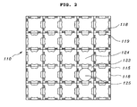
- FIG. 2 is a plan view schematically illustrating spacer grids applied to a conventional nuclear fuel assembly.
- FIG. 3 is a perspective view schematically illustrating spacer grids applied to a conventional nuclear fuel assembly.
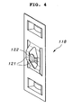
- FIG. 4 is a perspective view schematically illustrating spacer grid spring for spacer grids applied to a conventional nuclear fuel assembly.
- FIG. 5 schematically illustrates deformation of spacer grid spring, which is applied to spacer grids of a conventional nuclear fuel assembly, caused by one nuclear fuel rod.
- the conventional nuclear fuel assembly 2 to which spacer grids 110 are applied has a plurality of guide tubes 113 fitted between a top end piece 111 and a bottom end piece 112.
- the spacer grids 110 supporting nuclear fuel rods 125 form the nuclear fuel assembly 2 by means of welding with the guide tubes 113 in the longitudinal direction of the guide tubes 113 at regular intervals.
- the spacer grids 110 is usually formed of zircaloy, and includes nuclear fuel rod cells 123 that support the nuclear fuel rods 125, and guide tube cells 124 into which the guide tubes 113 are inserted, wherein each nuclear fuel rod cell 123 is designed such that two spacer grid springs 118 and the total of four dimples 119, which are each located on a top side and a bottom side of each spacer grid spring 118, contact and support each nuclear fuel rod 125 at six supporting points.
- each support 121 of each spacer grid spring 118 is pressed by each nuclear fuel rod 125.
- the rigidity of each support 121 is similar to that of a central curvature 122, which is connected with the two supports 121 and is contact with each nuclear fuel rod 125, each support 121 is simultaneously subjected to bending 131 and twisting 132 due to a load 130 applied by each nuclear fuel rod 125, as illustrated by arrows in FIG. 5.
- each nuclear fuel rod 125 When these bending and twisting deformations act on each support at the same time, each nuclear fuel rod 125 is unstably supported, and thus slight sliding occurs between the nuclear fuel rod 125 and the central curvature 122 contacting the nuclear fuel rod 125. As a result, desired conformal surface contact does not occur, thus causing stress concentration. This stress concentration makes the spacer grid spring vulnerable to fatigue, so that each nuclear fuel rod 125 has a high possibility of increasing the fretting wear thereof.
- the deformation of the central curvature 122 provides a high possibility of losing the original surface contact profile, and thus exerts an influence on stress distribution and magnitude of peak stress.
- each grid strap 115 has the same radius of curvature as the nuclear fuel rods 125, and thus are in conformal surface contact with the nuclear fuel rods 125 from the beginning. Thereafter, when the spacer grid spring 118 receives the load of each nuclear fuel rod 125, the central curvature 122 contacting respective nuclear fuel rod 125, and its support 121 are deformed at the same time.
- each nuclear fuel rod 125 cannot be arranged at designated positions, and thereby have a possibility of losing sound supporting performance.
- each nuclear fuel rod 125 undergoes defects such as scratching on the surface thereof due to excessive frictional resistance when inserted into the spacer grid 110.
- the nuclear fuel rods 125 experience longitudinal growth by means of irradiation of neutrons. This longitudinal growth is not properly accepted, and thus the nuclear fuel rods 125 are bent.
- a method of changing the geometry of the spacer grid is employed, and may include the attachment of a hybrid vane or a change in its design, or effective construction of a fluid channel.
- the flow induced vibration of the nuclear fuel rods is a factor generating mutual relative motion, in which the nuclear fuel rods slide on the contact surfaces with the spacer grid springs or the dimples of the grid straps. For this reason, the contact surfaces of the nuclear fuel rods are subjected to local wear, which incurs "fretting damage to the nuclear fuel rods", in which the nuclear fuel rods are gradually damaged.
- the contact surfaces between the nuclear fuel rods and the spacer grid springs or dimples of the grid straps are worn, so that the nuclear fuel rods are locally damaged. When this damage becomes serious, the nuclear fuel rods can be broken.
- the method of raising the thermal performance of the nuclear fuel in order to develop high-combustion nuclear fuel leads instead in damage to the nuclear fuel rods.
- the spacer grids serving to support the nuclear fuel rods must be able to maintain reliable supporting performance during the lifetime of the nuclear fuel rods, and to inhibit the possibility of fretting wear of the nuclear fuel rods.
- the spacer grid springs In this manner, in order to allow the nuclear fuel rods to maintain reliable supporting performance for the lifetime of the nuclear fuel rods, the spacer grid springs must be able to support the nuclear fuel rods with sufficient spring force for the lifetime of the nuclear fuel rods, and to maintain at least enough spring force to support the nuclear fuel rods, which can be variously changed in the nuclear reactor up to the lifetime of the nuclear fuel rods, by expanding the elastic behavior region of the spacer grid springs.
- the spacer grid springs and dimples gradually lose the initial spring force applied to the nuclear fuel rods due to the irradiation of the neutrons.
- a gap can develop between the nuclear fuel rods and their supports, and reliable supporting performance of the nuclear fuel rods can be lost by means of the load acting on the nuclear fuel rods in an arbitrary direction due to the flow of the coolant.
- the causes of fretting wear must be reduced. These causes generate the gap between the nuclear fuel rods and the supports of the spacer grids due to reduction of the spring force caused by the neutron irradiation, thermal expansion difference between the nuclear fuel rods and the spacer grids, diametrical reduction of the nuclear fuel rods caused by the elongation of the nuclear fuel rods, and so on.
- the nuclear fuel rods are vibrated by the turbulent flow caused by the coolant flow, and thus fretting wear is accelerated.
- an object of the present invention is to provide spacer grid spring that increases the conformal contact area with a fuel rod, in which the spacer grid spring of the grid strap, which is in contact with the fuel rod, is optimized in shape, thereby the elasticity of the spacer grid spring contacting the fuel rod is increased, the conformal contact area with a contact portion of the spacer grid spring contacting the fuel rod when the fuel rod is inserted into each cell of a spacer grid spring is expanded to obtain uniform stress distribution, and excessive plastic deformation of the spacer grid spring can be reduced, in which the magnitude and distribution of contact pressure between the fuel rod and the spacer grid spring are improved, thereby reducing the possibility of fretting wear caused by contact between the fuel rod and the spacer grid spring, and in which a elastic behavior region of the spacer grid spring is expanded, so that the fuel rod can be stably supported until the lifetime of the fuel rod expires despite changes in the supporting conditions of the fuel rod.
- grid strap for spacer grids including upper and lower plates having dimples protruding on one side respectively, and a spacer grid spring which connects the upper and lower plates and is in direct contact with a fuel rod
- the spacer grid spring includes upper and lower bases that vertically extend from the middle of the lower end of the upper plate and the middle of the upper end of the lower plate respectively, upper left-hand and right-hand supports and lower left-hand and right-hand supports that branch off from the upper and lower bases, respectively, and are symmetrical with each other, bridges that are connected between the upper and lower left-hand supports and between the upper and lower right-hand supports, and a conformal curvature that is connected between the bridges, protrudes in a direction opposite the dimples, is in direct contact with the fuel rod, and is curved inwards to allow upper and lower ends thereof to have a semi-circular form.
- each of the bridges located on opposite sides of the conformal curvature may be curved outwards in a semi-circular form, and may have a wedge shape formed on one end thereof.
- the spacer grid spring may include connecting pieces that connect the upper and lower plates at proper positions spaced apart from left-hand and right-hand supports in outward directions by a predetermined distance.
- FIG. 6 is a perspective view illustrating a grid strap having a spacer grid spring that increases the conformal contact area with a nuclear fuel rod in accordance with an embodiment of the present invention.
- FIG. 7 is a front view illustrating a grid strap having a spacer grid spring that increases the conformal contact area with a nuclear fuel rod in accordance with an embodiment of the present invention.
- FIG. 8 is a plan view illustrating a grid strap having a spacer grid spring that increases the conformal contact area with a nuclear fuel rod in accordance with an embodiment of the present invention.
- FIG. 9 is a perspective view schematically illustrating one cell of spacer grids made by using grid straps having a spacer grid spring that increases the conformal contact area with a nuclear fuel rod in accordance with an embodiment of the present invention.
- FIG. 10 is a perspective view schematically illustrating a spacer grid made using grid straps having a spacer grid spring that increases the conformal contact area with a nuclear fuel rod in accordance with an embodiment of the present invention.
- the spacer grid spring 14 that increases the conformal contact area with a fuel rod 3 is provided between upper and lower plates 11a and 11b which have the dimples 12a and 12b, respectively.
- the spacer grid spring 14 of the grid strap 10 of the present invention is provided between a lower end of the upper plate 11a and an upper end of the lower plate 11b, at the centers of which the dimples 12a and 12b protrude toward one side in place. Further, the spacer grid spring 14 connects the upper and lower plates 11a and 11b, and is in direct contact with the fuel rod 3.
- the spacer grid spring 14 includes upper and lower bases 15a and 15b that vertically extend from the middle of the lower end of the upper plate 11a and the middle of the upper end of the lower plate 11b respectively, upper left-hand and right-hand supports 16a and 16b and lower left-hand and right-hand supports 16a and 16b that branch off from the upper and lower bases 15a and 15b respectively and are symmetrical with each other, bridges 18a and 18b that are connected between the upper and lower left-hand supports 16a and between the upper and lower right-hand supports 16b, and a conformal curvature 17 that is connected between the bridges 18a and 18b, protrudes in a direction opposite the dimples 12a and 12b, and is in direct contact with the fuel rod 3.
- the conformal curvature 17 of the spacer grid spring 14 is curved inwards to allow upper and lower ends 21a and 21b thereof to have a semi-circular form.
- the conformal curvature 17 is designed such that the middle portion and upper and lower ends 21a and 21b thereof contacting the fuel rod 3 are curved inwards in a circular or elliptical form so as to have the same radius of curvature at the same central point as the fuel rod 3 and to be in conformal contact with the fuel rod 3.
- the conformal curvature 17 can expand the contact area with the fuel rod 3, uniformly maintain contact pressure distribution, and reduce the magnitude of peak stress.
- Each of the bridges 18a and 18b located on opposite sides of the conformal curvature 17 is curved outwards in a semi-circular form, and is formed in a wedge shape on one end thereof.
- each of the bridges 18a and 18b, which are located on opposite sides of the conformal curvature 17, has a semi-circular form curved outwards near the conformal curvature 17, and a wedge shape on the end thereof.
- the conformal curvature 17 is curved inwards to allow the upper and lower ends 21a and 21b thereof to have the semi-circular form, and the bridges 18a and 18b, which are located on the opposite sides of the conformal curvature 17, are curved outwards in the semi-circular form.
- the left-hand and right-hand supports 16a and 16b which branch off from the upper and lower bases 15a and 15b extending from the centers of the lower and upper ends of the upper and lower plates 11a and 11b, minimize twisting deformation, so that the surface contact between the fuel rod 3 and the conformal curvature 17 can be maintained.
- the left-hand and right-hand supports 16a and 16b are adapted to have relatively lower rigidity by bending compared to the rigidity of the conformal curvature 17, thereby being elastically deformed before the conformal curvature 17 is deformed by the load of the fuel rod 3 applied to the conformal curvature 17 of the spacer grid spring 14.
- the grid strap 10 having the spacer grid spring 14 of the above-mentioned shape and form is designed so that both the conformal curvature 17 of the spacer grid spring 14 and the dimples 12a and 12b are in surface contact with the outer circumference of the fuel rod 3 when the fuel 3 is inserted into each cell of the spacer grids 1.
- the conformal curvature 17 of the spacer grid spring 14, which is in surface contact with the outer circumference of the fuel rod 3, and the bridges 18a and 18b of the spacer grid spring 14 are deformed in shape and form, thereby expanding the conformal contact area with the fuel rod 3.
- sliding of the conformal curvature 17 relative to the fuel rod 3 is reduced, so that the fuel rod 3 is reliably held, and the possibility of fretting wear occurring on the surface of the fuel rod 3 is reduced.
- the conformal curvature 17 of the spacer grid spring 14 is curved inwards to allow the upper and lower ends thereof to have the semi-circular form, thereby preventing a change in the curvature thereof.
- a change in the relatively minute amount of sliding between the fuel rod 3 and the conformal curvature 17 is minimized, thereby the fuel rod 3 can be stably supported regardless of changes in the supporting conditions of the fuel rod 3.
- FIG. 11 is a perspective view illustrating a grid strap having a spacer grid spring that increases the conformal contact area with a nuclear fuel rod in accordance with another embodiment of the present invention.
- FIG. 12 is a front view illustrating a grid strap having a spacer grid spring in accordance with another embodiment of the present invention.
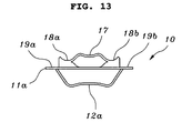
- FIG. 13 is a plan view illustrating a grid strap having a spacer grid spring in accordance with another embodiment of the present invention.
- FIG. 14 is a perspective view schematically illustrating one cell of spacer grids made using grid straps having a spacer grid spring in accordance with another embodiment of the present invention.
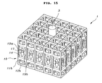
- FIG. 15 is a perspective view schematically illustrating spacer grids made by using grid straps having a spacer grid spring in accordance with another embodiment of the present invention.
- the spacer grid spring is partly changed in shape and form, compared to the previous embodiment.
- the spacer grid spring 14 which increases the conformal contact area with a nuclear fuel rod in accordance with the present embodiment, includes connecting pieces 19a and 19b that connect upper and lower plates 11a and 11b at proper positions spaced apart from left- and right-hand supports 16a and 16b, which are provided on left- and right-hand sides of a conformal curvature 17, in outward directions by a predetermined distance.
- the connecting pieces 19a and 19b connect the upper and lower plates 11a and 11b at proper positions located outside the left- and right-hand supports 16a and 16b, which are connected with bridges 18a and 18b on opposite sides of the conformal curvature 17, and predetermined spaces are formed between the connecting pieces 19a and 19b and the left- and right-hand supports 16a and 16b.
- the grid strap 10 having the spacer grid spring 14 of the above-mentioned shape and form is designed so that both the conformal curvature 17 of the spacer grid spring 14 and the dimples 12a and 12b are in surface contact with the outer circumference of the fuel rod 3 when the fuel rod 3 is inserted into a cell of the spacer grids 1, and so that the connecting pieces 19a and 19b are provided on the opposite sides of the conformal curvature 17 contacting the fuel rod 3.
- the conformal curvature 17 contacting the fuel rod 3 is prevented from being changed in the curvature thereof.
- a change in the relatively minute amount of sliding between the fuel rod 3 and the conformal curvature 17 is minimized, thereby the fuel rod 3 can be stably supported regardless of a change in the supporting conditions of the fuel rod 3.
- the spacer grid spring of the grid strap which is in contact with the fuel rod, is optimized in shape, thereby the elasticity of the spacer grid spring contacting the fuel rod is increased, the conformal contact area with the contact portion of the spacer grid spring contacting the fuel rod when the fuel rod is inserted into each cell of the spacer grid spring is expanded to realize uniform stress distribution, and excessive plastic deformation of the spacer grid spring can be reduced. Further, the magnitude and distribution of the contact pressure between the fuel rod and the spacer grid spring are improved, thereby reducing the possibility of fretting wear caused by contact between the fuel rod and the spacer grid spring.
- the elastic behavior region of the spacer grid spring is expanded, so that the fuel rod can be stably supported until the lifetime of the fuel rod is expired despite changes in the supporting conditions of the fuel rod.
- the grid strap can inhibit breakdown caused by wear, fatigue, and vibration between a piping system transporting a fluid and its supporting structure and between elongate rods or pipes and supports for supporting them in the general industrial equipment using a boiler or heat exchanger, and thus can be applied to various fields.
Landscapes
- Physics & Mathematics (AREA)
- Engineering & Computer Science (AREA)
- Plasma & Fusion (AREA)
- General Engineering & Computer Science (AREA)
- High Energy & Nuclear Physics (AREA)
- Springs (AREA)
- Monitoring And Testing Of Nuclear Reactors (AREA)
Abstract
Description
- The present invention relates to spacer grid spring that increases the conformal contact area with a fuel rod and, more particularly, to spacer grid spring that increases the conformal contact area with a fuel rod, in which the spacer grid spring of the grid strap, which is in contact with the fuel rod, is optimized in shape, thereby the elasticity of the spacer grid spring contacting the fuel rod is increased, the conformal contact area with a contact portion of the spacer grid spring contacting the fuel rod when the fuel rod is inserted into each cell of a spacer grid spring is expanded to realize uniform stress distribution, and excessive plastic deformation of the spacer grid spring can be reduced, and in which magnitude and distribution of contact pressure between the fuel rod and the spacer grid spring are improved, thereby reducing the possibility of fretting wear caused by contact between the fuel rod and the spacer grid spring.
- In general, spacer grids is one of the components constituting a nuclear fuel assembly in a nuclear reactor, and functions to arrange and support nuclear fuel rods, which constitute unit grid cells thereof, at designated positions by mutually connecting a plurality of straps, each of which has a spacer grid spring and dimples.
- FIG. 1 is a perspective view schematically illustrating a conventional nuclear fuel assembly. FIG. 2 is a plan view schematically illustrating spacer grids applied to a conventional nuclear fuel assembly. FIG. 3 is a perspective view schematically illustrating spacer grids applied to a conventional nuclear fuel assembly. FIG. 4 is a perspective view schematically illustrating spacer grid spring for spacer grids applied to a conventional nuclear fuel assembly. FIG. 5 schematically illustrates deformation of spacer grid spring, which is applied to spacer grids of a conventional nuclear fuel assembly, caused by one nuclear fuel rod.
- As illustrated in the figures, the conventional
nuclear fuel assembly 2 to whichspacer grids 110 are applied has a plurality ofguide tubes 113 fitted between atop end piece 111 and abottom end piece 112. - Here, the
spacer grids 110 supportingnuclear fuel rods 125 form thenuclear fuel assembly 2 by means of welding with theguide tubes 113 in the longitudinal direction of theguide tubes 113 at regular intervals. - Meanwhile, the
spacer grids 110 is usually formed of zircaloy, and includes nuclearfuel rod cells 123 that support thenuclear fuel rods 125, andguide tube cells 124 into which theguide tubes 113 are inserted, wherein each nuclearfuel rod cell 123 is designed such that twospacer grid springs 118 and the total of fourdimples 119, which are each located on a top side and a bottom side of eachspacer grid spring 118, contact and support eachnuclear fuel rod 125 at six supporting points. - Thus, when the
spacer grid springs 118 are in contact with thenuclear fuel rods 125 and are deformed by thenuclear fuel rods 125, two supports 121 of eachspacer grid spring 118 are pressed by eachnuclear fuel rod 125. Here, because the rigidity of eachsupport 121 is similar to that of acentral curvature 122, which is connected with the two supports 121 and is contact with eachnuclear fuel rod 125, eachsupport 121 is simultaneously subjected to bending 131 and twisting 132 due to aload 130 applied by eachnuclear fuel rod 125, as illustrated by arrows in FIG. 5. - When these bending and twisting deformations act on each support at the same time, each
nuclear fuel rod 125 is unstably supported, and thus slight sliding occurs between thenuclear fuel rod 125 and thecentral curvature 122 contacting thenuclear fuel rod 125. As a result, desired conformal surface contact does not occur, thus causing stress concentration. This stress concentration makes the spacer grid spring vulnerable to fatigue, so that eachnuclear fuel rod 125 has a high possibility of increasing the fretting wear thereof. - Further, the deformation of the
central curvature 122 provides a high possibility of losing the original surface contact profile, and thus exerts an influence on stress distribution and magnitude of peak stress. - Meanwhile, the
spacer grid spring 118 and thedimples 119 of eachgrid strap 115 have the same radius of curvature as thenuclear fuel rods 125, and thus are in conformal surface contact with thenuclear fuel rods 125 from the beginning. Thereafter, when thespacer grid spring 118 receives the load of eachnuclear fuel rod 125, thecentral curvature 122 contacting respectivenuclear fuel rod 125, and itssupport 121 are deformed at the same time. - Further, when spring force of the
spacer grid spring 118 and dimples 119 of eachgrid strap 115 is too weak, thenuclear fuel rods 125 cannot be arranged at designated positions, and thereby have a possibility of losing sound supporting performance. When the spring force is too high, eachnuclear fuel rod 125 undergoes defects such as scratching on the surface thereof due to excessive frictional resistance when inserted into thespacer grid 110. Further, during operation of the nuclear reactor, thenuclear fuel rods 125 experience longitudinal growth by means of irradiation of neutrons. This longitudinal growth is not properly accepted, and thus thenuclear fuel rods 125 are bent. - In this manner, when the nuclear fuel rods are bent, the neighboring nuclear fuel rods become too near each other or contact each other. Thus, the coolant channel between the neighboring nuclear fuel rods becomes narrow or is blocked. As a result, heat generated from the nuclear fuel rods is not effectively transmitted to the coolant, thereby increasing the temperature of the nuclear fuel rods. As such, the possibility of generating departure from nucleate boiling (DNB) is increased, which is mainly responsible for the reduction of nuclear fuel output.
- In order to solve the above-described problems, recent nuclear fuel development has focused on high combustion and zero defects. In particular, to develop high-combustion nuclear fuel, the thermal performance of the nuclear fuel for promoting heat transmission from the nuclear fuel rods to the coolant must be increased. To this end, a method of improving the flow of the coolant flowing around the nuclear fuel rods is required.
- Here, as the method of improving the flow of the coolant flowing around the nuclear fuel rods, a method of changing the geometry of the spacer grid is employed, and may include the attachment of a hybrid vane or a change in its design, or effective construction of a fluid channel.
- However, most concepts for raising this thermal performance are based on the principle that the flow of the coolant flowing around the nuclear fuel rods is very turbulent, the flow has a high Reynolds number. In this manner, the turbulence of the coolant flow around the nuclear fuel rods is mainly responsible for flow induced vibration of the nuclear fuel rods.
- The flow induced vibration of the nuclear fuel rods is a factor generating mutual relative motion, in which the nuclear fuel rods slide on the contact surfaces with the spacer grid springs or the dimples of the grid straps. For this reason, the contact surfaces of the nuclear fuel rods are subjected to local wear, which incurs "fretting damage to the nuclear fuel rods", in which the nuclear fuel rods are gradually damaged.
- In other words, the contact surfaces between the nuclear fuel rods and the spacer grid springs or dimples of the grid straps are worn, so that the nuclear fuel rods are locally damaged. When this damage becomes serious, the nuclear fuel rods can be broken.
- Therefore, the method of raising the thermal performance of the nuclear fuel in order to develop high-combustion nuclear fuel leads instead in damage to the nuclear fuel rods.
- As described above, the spacer grids serving to support the nuclear fuel rods must be able to maintain reliable supporting performance during the lifetime of the nuclear fuel rods, and to inhibit the possibility of fretting wear of the nuclear fuel rods.
- In this manner, in order to allow the nuclear fuel rods to maintain reliable supporting performance for the lifetime of the nuclear fuel rods, the spacer grid springs must be able to support the nuclear fuel rods with sufficient spring force for the lifetime of the nuclear fuel rods, and to maintain at least enough spring force to support the nuclear fuel rods, which can be variously changed in the nuclear reactor up to the lifetime of the nuclear fuel rods, by expanding the elastic behavior region of the spacer grid springs.
- However, during the operation of the nuclear reactor, the spacer grid springs and dimples gradually lose the initial spring force applied to the nuclear fuel rods due to the irradiation of the neutrons. As a result, a gap can develop between the nuclear fuel rods and their supports, and reliable supporting performance of the nuclear fuel rods can be lost by means of the load acting on the nuclear fuel rods in an arbitrary direction due to the flow of the coolant.
- Further, in order to inhibit the possibility of the fretting wear of the nuclear fuel rods, the causes of fretting wear must be reduced. These causes generate the gap between the nuclear fuel rods and the supports of the spacer grids due to reduction of the spring force caused by the neutron irradiation, thermal expansion difference between the nuclear fuel rods and the spacer grids, diametrical reduction of the nuclear fuel rods caused by the elongation of the nuclear fuel rods, and so on. The nuclear fuel rods are vibrated by the turbulent flow caused by the coolant flow, and thus fretting wear is accelerated.
- Accordingly, the present invention has been made keeping in mind the above problems occurring in the prior art, and an object of the present invention is to provide spacer grid spring that increases the conformal contact area with a fuel rod, in which the spacer grid spring of the grid strap, which is in contact with the fuel rod, is optimized in shape, thereby the elasticity of the spacer grid spring contacting the fuel rod is increased, the conformal contact area with a contact portion of the spacer grid spring contacting the fuel rod when the fuel rod is inserted into each cell of a spacer grid spring is expanded to obtain uniform stress distribution, and excessive plastic deformation of the spacer grid spring can be reduced, in which the magnitude and distribution of contact pressure between the fuel rod and the spacer grid spring are improved, thereby reducing the possibility of fretting wear caused by contact between the fuel rod and the spacer grid spring, and in which a elastic behavior region of the spacer grid spring is expanded, so that the fuel rod can be stably supported until the lifetime of the fuel rod expires despite changes in the supporting conditions of the fuel rod.
- In order to achieve the above object, according to the present invention, there is provided grid strap for spacer grids including upper and lower plates having dimples protruding on one side respectively, and a spacer grid spring which connects the upper and lower plates and is in direct contact with a fuel rod, wherein the spacer grid spring includes upper and lower bases that vertically extend from the middle of the lower end of the upper plate and the middle of the upper end of the lower plate respectively, upper left-hand and right-hand supports and lower left-hand and right-hand supports that branch off from the upper and lower bases, respectively, and are symmetrical with each other, bridges that are connected between the upper and lower left-hand supports and between the upper and lower right-hand supports, and a conformal curvature that is connected between the bridges, protrudes in a direction opposite the dimples, is in direct contact with the fuel rod, and is curved inwards to allow upper and lower ends thereof to have a semi-circular form.
- Preferably, each of the bridges located on opposite sides of the conformal curvature may be curved outwards in a semi-circular form, and may have a wedge shape formed on one end thereof.
- Here, the spacer grid spring may include connecting pieces that connect the upper and lower plates at proper positions spaced apart from left-hand and right-hand supports in outward directions by a predetermined distance.
- The above and other objects, features and other advantages of the present invention will be more clearly understood from the following detailed description when taken in conjunction with the accompanying drawings, in which:
- FIG. 1 is a perspective view schematically illustrating a conventional nuclear fuel assembly;
- FIG. 2 is a plan view schematically illustrating spacer grids applied to a conventional nuclear fuel assembly;
- FIG. 3 is a perspective view schematically illustrating one spacer grids applied to a conventional nuclear fuel assembly;
- FIG. 4 is a perspective view schematically illustrating spacer grid spring for spacer grids applied to a conventional nuclear fuel assembly;
- FIG. 5 schematically illustrates the deformation of spacer grid spring, which is applied to spacer grids of a conventional nuclear fuel assembly, caused by one nuclear fuel rod;
- FIG. 6 is a perspective view illustrating a grid strap having a spacer grid spring that increases the conformal contact area with a nuclear fuel rod in accordance with an embodiment of the present invention;
- FIG. 7 is a front view illustrating a grid strap having a spacer grid spring that increases the conformal contact area with a nuclear fuel rod in accordance with an embodiment of the present invention;
- FIG. 8 is a plan view illustrating a grid strap having a spacer grid spring that increases the conformal contact area with a nuclear fuel rod in accordance with an embodiment of the present invention;
- FIG. 9 is a perspective view schematically illustrating one cell of spacer grids made by using grid straps having a spacer grid spring that increases the conformal contact area with a nuclear fuel rod in accordance with an embodiment of the present invention;
- FIG. 10 is a perspective view schematically illustrating a spacer grid made by using grid straps having a spacer grid spring that increases the conformal contact area with a nuclear fuel rod in accordance with an embodiment of the present invention;
- FIG. 11 is a perspective view illustrating a grid strap having a spacer grid spring that increases the conformal contact area with a nuclear fuel rod in accordance with another embodiment of the present invention;
- FIG. 12 is a front view illustrating a grid strap having a spacer grid spring in accordance with another embodiment of the present invention;
- FIG. 13 is a plan view illustrating a grid strap having a spacer grid spring in accordance with another embodiment of the present invention;
- FIG. 14 is a perspective view schematically illustrating one cell of spacer grids made by using grid straps having a spacer grid spring in accordance with another embodiment of the present invention; and
- FIG. 15 is a perspective view schematically illustrating spacer grids made by using grid straps having a spacer grid spring in accordance with another embodiment of the present invention.
- Reference will now be made in greater detail to an exemplary embodiment of the invention, which is illustrated in the accompanying drawings. Wherever possible, the same reference numerals will be used throughout the drawings and the description to refer to the same or like parts.
- FIG. 6 is a perspective view illustrating a grid strap having a spacer grid spring that increases the conformal contact area with a nuclear fuel rod in accordance with an embodiment of the present invention. FIG. 7 is a front view illustrating a grid strap having a spacer grid spring that increases the conformal contact area with a nuclear fuel rod in accordance with an embodiment of the present invention. FIG. 8 is a plan view illustrating a grid strap having a spacer grid spring that increases the conformal contact area with a nuclear fuel rod in accordance with an embodiment of the present invention. FIG. 9 is a perspective view schematically illustrating one cell of spacer grids made by using grid straps having a spacer grid spring that increases the conformal contact area with a nuclear fuel rod in accordance with an embodiment of the present invention. FIG. 10 is a perspective view schematically illustrating a spacer grid made using grid straps having a spacer grid spring that increases the conformal contact area with a nuclear fuel rod in accordance with an embodiment of the present invention.
- As illustrated in the figures, the
spacer grid spring 14 that increases the conformal contact area with afuel rod 3 is provided between upper andlower plates dimples - More specifically, the
spacer grid spring 14 of thegrid strap 10 of the present invention is provided between a lower end of theupper plate 11a and an upper end of thelower plate 11b, at the centers of which thedimples spacer grid spring 14 connects the upper andlower plates fuel rod 3. - The
spacer grid spring 14 includes upper andlower bases upper plate 11a and the middle of the upper end of thelower plate 11b respectively, upper left-hand and right-hand supports 16a and 16b and lower left-hand and right-hand supports 16a and 16b that branch off from the upper andlower bases conformal curvature 17 that is connected between thebridges dimples fuel rod 3. - Here, the
conformal curvature 17 of thespacer grid spring 14 is curved inwards to allow upper andlower ends 21a and 21b thereof to have a semi-circular form. In other words, theconformal curvature 17 is designed such that the middle portion and upper andlower ends 21a and 21b thereof contacting thefuel rod 3 are curved inwards in a circular or elliptical form so as to have the same radius of curvature at the same central point as thefuel rod 3 and to be in conformal contact with thefuel rod 3. Thereby, theconformal curvature 17 can expand the contact area with thefuel rod 3, uniformly maintain contact pressure distribution, and reduce the magnitude of peak stress. - Each of the
bridges conformal curvature 17 is curved outwards in a semi-circular form, and is formed in a wedge shape on one end thereof. In other words, each of thebridges conformal curvature 17, has a semi-circular form curved outwards near theconformal curvature 17, and a wedge shape on the end thereof. - As described above, the
conformal curvature 17 is curved inwards to allow the upper andlower ends 21a and 21b thereof to have the semi-circular form, and thebridges conformal curvature 17, are curved outwards in the semi-circular form. - Meanwhile, even if pure bending deformation occurs when elastic deformation is caused by pressing the
conformal curvature 17 contacting thefuel rod 3, the left-hand and right-hand supports 16a and 16b, which branch off from the upper andlower bases lower plates fuel rod 3 and theconformal curvature 17 can be maintained. - To this end, the left-hand and right-hand supports 16a and 16b are adapted to have relatively lower rigidity by bending compared to the rigidity of the
conformal curvature 17, thereby being elastically deformed before theconformal curvature 17 is deformed by the load of thefuel rod 3 applied to theconformal curvature 17 of thespacer grid spring 14. - As illustrated in FIGS. 9 and 10, the
grid strap 10 having thespacer grid spring 14 of the above-mentioned shape and form is designed so that both theconformal curvature 17 of thespacer grid spring 14 and thedimples fuel rod 3 when thefuel 3 is inserted into each cell of thespacer grids 1. - In this manner, the
conformal curvature 17 of thespacer grid spring 14, which is in surface contact with the outer circumference of thefuel rod 3, and thebridges spacer grid spring 14 are deformed in shape and form, thereby expanding the conformal contact area with thefuel rod 3. Thus, sliding of theconformal curvature 17 relative to thefuel rod 3 is reduced, so that thefuel rod 3 is reliably held, and the possibility of fretting wear occurring on the surface of thefuel rod 3 is reduced. - Further, the
conformal curvature 17 of thespacer grid spring 14 is curved inwards to allow the upper and lower ends thereof to have the semi-circular form, thereby preventing a change in the curvature thereof. A change in the relatively minute amount of sliding between thefuel rod 3 and theconformal curvature 17 is minimized, thereby thefuel rod 3 can be stably supported regardless of changes in the supporting conditions of thefuel rod 3. - FIG. 11 is a perspective view illustrating a grid strap having a spacer grid spring that increases the conformal contact area with a nuclear fuel rod in accordance with another embodiment of the present invention. FIG. 12 is a front view illustrating a grid strap having a spacer grid spring in accordance with another embodiment of the present invention. FIG. 13 is a plan view illustrating a grid strap having a spacer grid spring in accordance with another embodiment of the present invention. FIG. 14 is a perspective view schematically illustrating one cell of spacer grids made using grid straps having a spacer grid spring in accordance with another embodiment of the present invention. FIG. 15 is a perspective view schematically illustrating spacer grids made by using grid straps having a spacer grid spring in accordance with another embodiment of the present invention. The spacer grid spring is partly changed in shape and form, compared to the previous embodiment.
- As illustrated in the figures, the
spacer grid spring 14, which increases the conformal contact area with a nuclear fuel rod in accordance with the present embodiment, includes connectingpieces lower plates conformal curvature 17, in outward directions by a predetermined distance. - More specifically, the connecting
pieces lower plates bridges conformal curvature 17, and predetermined spaces are formed between the connectingpieces - As illustrated in FIGS. 14 and 15, the
grid strap 10 having thespacer grid spring 14 of the above-mentioned shape and form is designed so that both theconformal curvature 17 of thespacer grid spring 14 and thedimples fuel rod 3 when thefuel rod 3 is inserted into a cell of thespacer grids 1, and so that the connectingpieces conformal curvature 17 contacting thefuel rod 3. Thereby, theconformal curvature 17 contacting thefuel rod 3 is prevented from being changed in the curvature thereof. Further, a change in the relatively minute amount of sliding between thefuel rod 3 and theconformal curvature 17 is minimized, thereby thefuel rod 3 can be stably supported regardless of a change in the supporting conditions of thefuel rod 3. - As is apparent from the above description, according to the present invention, the spacer grid spring of the grid strap, which is in contact with the fuel rod, is optimized in shape, thereby the elasticity of the spacer grid spring contacting the fuel rod is increased, the conformal contact area with the contact portion of the spacer grid spring contacting the fuel rod when the fuel rod is inserted into each cell of the spacer grid spring is expanded to realize uniform stress distribution, and excessive plastic deformation of the spacer grid spring can be reduced. Further, the magnitude and distribution of the contact pressure between the fuel rod and the spacer grid spring are improved, thereby reducing the possibility of fretting wear caused by contact between the fuel rod and the spacer grid spring. The elastic behavior region of the spacer grid spring is expanded, so that the fuel rod can be stably supported until the lifetime of the fuel rod is expired despite changes in the supporting conditions of the fuel rod. In addition, the grid strap can inhibit breakdown caused by wear, fatigue, and vibration between a piping system transporting a fluid and its supporting structure and between elongate rods or pipes and supports for supporting them in the general industrial equipment using a boiler or heat exchanger, and thus can be applied to various fields.
- Although an exemplary embodiment of the present invention has been described for illustrative purposes, those skilled in the art will appreciate that various modifications, additions and substitutions are possible, without departing from the scope and spirit of the invention as disclosed in the accompanying claims.
Claims (3)
- Grid strap for spacer grids comprising:upper and lower plates (11a and 11b) having respective dimples (12a and 12b) protruding on one sides thereof; anda spacer grid spring (14) connecting the upper and lower plates (11a and 11b) and being in direct contact with a fuel rod (3),wherein the spacer grid spring (14) includes upper and lower bases (15a and 15b) that vertically extend from a center of a lower end of the upper plate (11a) and a center of an upper end of the lower plate (11b) respectively, upper left-hand and right-hand supports (16a and 16b) and lower left-hand and right-hand supports (16a and 16b) that branch off from the upper and lower bases (15a and 15b) respectively and are symmetrical with each other, bridges (18a and 18b) that are connected between the upper and lower left-hand supports (16a) and between the upper and lower right-hand supports (16b), and a conformal curvature (17) that is connected between the bridges (18a and 18b), protrudes in a direction opposite the dimples (12a and 12b), is in direct contact with the fuel rod (3), and is curved inwards to allow upper and lower ends (21a and 21b) thereof to have a semi-circular form.
- The spacer grids as claimed in claim 1, wherein each of the bridges (18a and 18b) located on opposite sides of the conformal curvature (17) is curved outwards in a semi-circular form, and is formed in a wedge shape on one end thereof.
- The spacer grids as claimed in claim 1, wherein the spacer grid spring (14) includes connecting pieces (19a and 19b) that connect the upper and lower plates (11a and 11b) at proper positions spaced apart from left-hand and right-hand supports (16a and 16b) in outward directions by a predetermined distance.
Applications Claiming Priority (1)
| Application Number | Priority Date | Filing Date | Title |
|---|---|---|---|
| KR1020060033570A KR20070102001A (en) | 2006-04-13 | 2006-04-13 | Support grid spring increases fuel rod and conformal contact area |
Publications (1)
| Publication Number | Publication Date |
|---|---|
| EP1845533A1 true EP1845533A1 (en) | 2007-10-17 |
Family
ID=38169464
Family Applications (1)
| Application Number | Title | Priority Date | Filing Date |
|---|---|---|---|
| EP07290236A Ceased EP1845533A1 (en) | 2006-04-13 | 2007-02-23 | Spacer grid spring for increasing the conformal contact area with fuel rod |
Country Status (5)
| Country | Link |
|---|---|
| US (1) | US8085895B2 (en) |
| EP (1) | EP1845533A1 (en) |
| JP (1) | JP4970969B2 (en) |
| KR (1) | KR20070102001A (en) |
| CN (1) | CN101055775B (en) |
Cited By (1)
| Publication number | Priority date | Publication date | Assignee | Title |
|---|---|---|---|---|
| FR2995124A1 (en) * | 2012-09-04 | 2014-03-07 | Global Nuclear Fuel Americas | SPACING GRILLS WITH LIMITED-DEVIATION PENCIL CONTACTS FOR NUCLEAR COMBUSTIBLE ASSEMBLIES AND METHODS OF MAKING SAME |
Families Citing this family (24)
| Publication number | Priority date | Publication date | Assignee | Title |
|---|---|---|---|---|
| SE530864C2 (en) * | 2007-02-05 | 2008-09-30 | Westinghouse Electric Sweden | Process for producing nuclear reactor spreader |
| AU2007363064B2 (en) | 2007-12-26 | 2014-02-13 | Thorium Power Inc. | Nuclear reactor (variants), fuel assembly consisting of driver-breeding modules for a nuclear reactor (variants) and a fuel cell for a fuel assembly |
| US8116423B2 (en) | 2007-12-26 | 2012-02-14 | Thorium Power, Inc. | Nuclear reactor (alternatives), fuel assembly of seed-blanket subassemblies for nuclear reactor (alternatives), and fuel element for fuel assembly |
| KR100981667B1 (en) * | 2008-07-03 | 2010-09-13 | 한국원자력연구원 | Support grid strap for stable support of nuclear fuel rods in the reactor |
| JP5755568B2 (en) | 2008-12-25 | 2015-07-29 | トリウム・パワー、インクThorium Power,Inc. | Light water reactor nuclear fuel assembly and light water reactor |
| US9053827B2 (en) * | 2009-03-27 | 2015-06-09 | Westinghouse Electric Company Llc | Nuclear fuel assembly with pivot dimpled grids |
| US10170207B2 (en) | 2013-05-10 | 2019-01-01 | Thorium Power, Inc. | Fuel assembly |
| WO2011143172A1 (en) | 2010-05-11 | 2011-11-17 | Thorium Power, Inc. | Fuel assembly with metal fuel alloy kernel and method of manufacturing thereof |
| US10192644B2 (en) | 2010-05-11 | 2019-01-29 | Lightbridge Corporation | Fuel assembly |
| CN102476149B (en) * | 2010-11-23 | 2013-10-23 | 中核建中核燃料元件有限公司 | Positioning lattice frame spring punching method |
| EP2525366A1 (en) | 2011-05-20 | 2012-11-21 | Areva NP | Strip for a nuclear fuel assembly spacer grid |
| EP2525363A1 (en) | 2011-05-20 | 2012-11-21 | Areva NP | Strip for a nuclear fuel assembly spacer grid |
| US9881701B2 (en) * | 2012-04-17 | 2018-01-30 | Bwxt Mpower, Inc. | Spacer grids with springs having improved robustness |
| KR20140019924A (en) * | 2012-08-06 | 2014-02-18 | 한전원자력연료 주식회사 | Spacer grid of a nuclear fuel assembly to prevent flow-induced vibration |
| KR101442088B1 (en) * | 2012-08-06 | 2014-09-19 | 한전원자력연료 주식회사 | Spacer grid of a nuclear fuel assembly to prevent high frequency vibration |
| EP2741297A1 (en) * | 2012-12-04 | 2014-06-11 | Areva NP | Fuel rod support insert for a nuclear fuel assembly spacer grid, spacer grid and nuclear fuel assembly |
| WO2017219304A1 (en) * | 2016-06-23 | 2017-12-28 | 中广核研究院有限公司 | Fuel assembly and grid, strip and spring, on strip, thereof |
| CN107230501A (en) * | 2017-06-09 | 2017-10-03 | 中广核研究院有限公司 | A kind of nuclear fuel assembly, location grid and band |
| CN107221358A (en) * | 2017-06-09 | 2017-09-29 | 中广核研究院有限公司 | A kind of nuclear fuel assembly, location grid and spring |
| CN107980163B (en) * | 2017-09-20 | 2020-05-22 | 岭澳核电有限公司 | Spacer grid and fuel assembly |
| US10580875B2 (en) | 2018-01-17 | 2020-03-03 | Globalfoundries Inc. | Middle of line structures |
| CN111540481A (en) * | 2020-05-14 | 2020-08-14 | 吉林农业大学 | A mixing grid based on additive manufacturing process |
| CN111613351B (en) * | 2020-06-04 | 2022-05-20 | 中国核动力研究设计院 | Stress fatigue resistant single-metal positioning grid for pressurized water reactor fuel assembly |
| CN113362973B (en) * | 2021-06-04 | 2022-02-22 | 中国核动力研究设计院 | Grid spring for improving abrasion resistance and reducing resistance and positioning grid |
Citations (3)
| Publication number | Priority date | Publication date | Assignee | Title |
|---|---|---|---|---|
| US6167105A (en) * | 1997-12-22 | 2000-12-26 | Korea Atomic Energy Research Institute | Spacer grid with H-spring for fuel rods for use in nuclear reactor fuel assemblies |
| US20030012329A1 (en) * | 2001-07-10 | 2003-01-16 | Yoon Kyung Ho | Spacer grid for nuclear reactor fuel assemblies with grid springs maintaining conformal contact with fuel rods and enlarged elastic range |
| US6606369B1 (en) * | 2002-03-06 | 2003-08-12 | Westinghouse Electric Company Llc | Nuclear reactor with improved grid |
Family Cites Families (4)
| Publication number | Priority date | Publication date | Assignee | Title |
|---|---|---|---|---|
| US4389369A (en) * | 1980-08-11 | 1983-06-21 | Westinghouse Electric Corp. | Bi-metallic grid for a nuclear reactor fuel assembly |
| US4659542A (en) * | 1984-10-03 | 1987-04-21 | Westinghouse Electric Corp. | Grid structure for nuclear fuel assembly |
| US4702881A (en) * | 1985-04-02 | 1987-10-27 | Westinghouse Electric Corp. | Nuclear reactor spacer grid |
| FR2736189B1 (en) * | 1995-06-29 | 1997-09-26 | Framatome Sa | GRID SPACER OF A FUEL ASSEMBLY FOR A NUCLEAR REACTOR HAVING ADDED SPRINGS |
-
2006
- 2006-04-13 KR KR1020060033570A patent/KR20070102001A/en not_active Ceased
-
2007
- 2007-01-30 JP JP2007018658A patent/JP4970969B2/en active Active
- 2007-02-16 US US11/707,450 patent/US8085895B2/en active Active
- 2007-02-23 EP EP07290236A patent/EP1845533A1/en not_active Ceased
- 2007-03-14 CN CN2007100857611A patent/CN101055775B/en not_active Expired - Fee Related
Patent Citations (3)
| Publication number | Priority date | Publication date | Assignee | Title |
|---|---|---|---|---|
| US6167105A (en) * | 1997-12-22 | 2000-12-26 | Korea Atomic Energy Research Institute | Spacer grid with H-spring for fuel rods for use in nuclear reactor fuel assemblies |
| US20030012329A1 (en) * | 2001-07-10 | 2003-01-16 | Yoon Kyung Ho | Spacer grid for nuclear reactor fuel assemblies with grid springs maintaining conformal contact with fuel rods and enlarged elastic range |
| US6606369B1 (en) * | 2002-03-06 | 2003-08-12 | Westinghouse Electric Company Llc | Nuclear reactor with improved grid |
Cited By (2)
| Publication number | Priority date | Publication date | Assignee | Title |
|---|---|---|---|---|
| FR2995124A1 (en) * | 2012-09-04 | 2014-03-07 | Global Nuclear Fuel Americas | SPACING GRILLS WITH LIMITED-DEVIATION PENCIL CONTACTS FOR NUCLEAR COMBUSTIBLE ASSEMBLIES AND METHODS OF MAKING SAME |
| US10176899B2 (en) | 2012-09-04 | 2019-01-08 | Global Nuclear Fuel-Americas, Llc | Spacers with deflection-limited rod contacts for nuclear fuel assemblies and methods of making the same |
Also Published As
| Publication number | Publication date |
|---|---|
| JP4970969B2 (en) | 2012-07-11 |
| US8085895B2 (en) | 2011-12-27 |
| KR20070102001A (en) | 2007-10-18 |
| US20070242793A1 (en) | 2007-10-18 |
| CN101055775B (en) | 2012-05-30 |
| CN101055775A (en) | 2007-10-17 |
| JP2007286039A (en) | 2007-11-01 |
Similar Documents
| Publication | Publication Date | Title |
|---|---|---|
| US8085895B2 (en) | Spacer grid spring for increasing the conformal contact area with fuel rod | |
| KR100432581B1 (en) | Spacer Grid for Uniform Conformal Contact with Fuel Rod and for Extending the Elastic Range of the Grid Spring | |
| US7769125B2 (en) | Spacer grid for nuclear reactor fuel assemblies | |
| US6167105A (en) | Spacer grid with H-spring for fuel rods for use in nuclear reactor fuel assemblies | |
| CN107980163B (en) | Spacer grid and fuel assembly | |
| KR100691345B1 (en) | Method for avoiding friction damages to fuel rods, corresponding nuclear fuel element, devices used in this method and corresponding spacer | |
| KR100771830B1 (en) | Support grid of nuclear fuel rods | |
| KR20030074250A (en) | Nuclear reactor with improved grid | |
| US6997141B2 (en) | Anti-vibration support for steam generator heat transfer tubes and method for making same | |
| JP5601671B2 (en) | Nuclear fuel assemblies with grids with pivoting dimples | |
| EP1978528B1 (en) | Fuel assembly and and insertable interelement spacer | |
| JP2011169899A (en) | Anti-fretting fuel rod support structure by split spring | |
| CN101589438B (en) | Grid with saddle support and corresponding nuclear fuel assembly | |
| KR101002719B1 (en) | Support grid spring with hole in contact | |
| US20040086072A1 (en) | Side-slotted nozzle type double sheet spacer grid for nuclear fuel assemblies | |
| US10176899B2 (en) | Spacers with deflection-limited rod contacts for nuclear fuel assemblies and methods of making the same | |
| US6714619B2 (en) | Spacer grid with double deflected vanes for nuclear fuel assemblies | |
| US4110160A (en) | Fuel assembly spacer within the coolant duct | |
| KR100981667B1 (en) | Support grid strap for stable support of nuclear fuel rods in the reactor | |
| US8243872B2 (en) | Spacer grid for close-spaced nuclear fuel rods | |
| KR100844879B1 (en) | Support grid with W and springs with improved fuel rod fretting wear resistance | |
| KR100877575B1 (en) | Optimal Design Method of Support Grid Strap for Supporting Fuel Rod of Nuclear Fuel Assembly and Supported Grid Strap | |
| KR102078907B1 (en) | Nuclear fuel rod for heavy-water reactor and nuclear fuel rod assembly having the same | |
| KR102039516B1 (en) | A support grid itself that stably supports the fuel rod | |
| KR100844883B1 (en) | Support grid with support wing springs and dimples to prevent fuel rod fretting wear |
Legal Events
| Date | Code | Title | Description |
|---|---|---|---|
| PUAI | Public reference made under article 153(3) epc to a published international application that has entered the european phase |
Free format text: ORIGINAL CODE: 0009012 |
|
| 17P | Request for examination filed |
Effective date: 20070302 |
|
| AK | Designated contracting states |
Kind code of ref document: A1 Designated state(s): AT BE BG CH CY CZ DE DK EE ES FI FR GB GR HU IE IS IT LI LT LU LV MC NL PL PT RO SE SI SK TR |
|
| AX | Request for extension of the european patent |
Extension state: AL BA HR MK YU |
|
| 17Q | First examination report despatched |
Effective date: 20080521 |
|
| AKX | Designation fees paid |
Designated state(s): AT BE BG CH CY CZ DE DK EE ES FI FR GB GR HU IE IS IT LI LT LU LV MC NL PL PT RO SE SI SK TR |
|
| R17C | First examination report despatched (corrected) |
Effective date: 20080521 |
|
| STAA | Information on the status of an ep patent application or granted ep patent |
Free format text: STATUS: THE APPLICATION HAS BEEN REFUSED |
|
| 18R | Application refused |
Effective date: 20100818 |