EP1845441A2 - Marking engine selection - Google Patents
Marking engine selection Download PDFInfo
- Publication number
- EP1845441A2 EP1845441A2 EP07105934A EP07105934A EP1845441A2 EP 1845441 A2 EP1845441 A2 EP 1845441A2 EP 07105934 A EP07105934 A EP 07105934A EP 07105934 A EP07105934 A EP 07105934A EP 1845441 A2 EP1845441 A2 EP 1845441A2
- Authority
- EP
- European Patent Office
- Prior art keywords
- marking
- job
- engine
- image quality
- engines
- Prior art date
- Legal status (The legal status is an assumption and is not a legal conclusion. Google has not performed a legal analysis and makes no representation as to the accuracy of the status listed.)
- Ceased
Links
Images



Classifications
-
- G—PHYSICS
- G06—COMPUTING OR CALCULATING; COUNTING
- G06F—ELECTRIC DIGITAL DATA PROCESSING
- G06F3/00—Input arrangements for transferring data to be processed into a form capable of being handled by the computer; Output arrangements for transferring data from processing unit to output unit, e.g. interface arrangements
- G06F3/12—Digital output to print unit, e.g. line printer, chain printer
- G06F3/1201—Dedicated interfaces to print systems
- G06F3/1223—Dedicated interfaces to print systems specifically adapted to use a particular technique
- G06F3/1237—Print job management
- G06F3/126—Job scheduling, e.g. queuing, determine appropriate device
-
- G—PHYSICS
- G03—PHOTOGRAPHY; CINEMATOGRAPHY; ANALOGOUS TECHNIQUES USING WAVES OTHER THAN OPTICAL WAVES; ELECTROGRAPHY; HOLOGRAPHY
- G03G—ELECTROGRAPHY; ELECTROPHOTOGRAPHY; MAGNETOGRAPHY
- G03G15/00—Apparatus for electrographic processes using a charge pattern
- G03G15/50—Machine control of apparatus for electrographic processes using a charge pattern, e.g. regulating differents parts of the machine, multimode copiers, microprocessor control
-
- G—PHYSICS
- G03—PHOTOGRAPHY; CINEMATOGRAPHY; ANALOGOUS TECHNIQUES USING WAVES OTHER THAN OPTICAL WAVES; ELECTROGRAPHY; HOLOGRAPHY
- G03G—ELECTROGRAPHY; ELECTROPHOTOGRAPHY; MAGNETOGRAPHY
- G03G15/00—Apparatus for electrographic processes using a charge pattern
- G03G15/50—Machine control of apparatus for electrographic processes using a charge pattern, e.g. regulating differents parts of the machine, multimode copiers, microprocessor control
- G03G15/5075—Remote control machines, e.g. by a host
- G03G15/5087—Remote control machines, e.g. by a host for receiving image data
-
- G—PHYSICS
- G06—COMPUTING OR CALCULATING; COUNTING
- G06F—ELECTRIC DIGITAL DATA PROCESSING
- G06F3/00—Input arrangements for transferring data to be processed into a form capable of being handled by the computer; Output arrangements for transferring data from processing unit to output unit, e.g. interface arrangements
- G06F3/12—Digital output to print unit, e.g. line printer, chain printer
- G06F3/1201—Dedicated interfaces to print systems
- G06F3/1202—Dedicated interfaces to print systems specifically adapted to achieve a particular effect
- G06F3/1203—Improving or facilitating administration, e.g. print management
- G06F3/1208—Improving or facilitating administration, e.g. print management resulting in improved quality of the output result, e.g. print layout, colours, workflows, print preview
-
- G—PHYSICS
- G06—COMPUTING OR CALCULATING; COUNTING
- G06F—ELECTRIC DIGITAL DATA PROCESSING
- G06F3/00—Input arrangements for transferring data to be processed into a form capable of being handled by the computer; Output arrangements for transferring data from processing unit to output unit, e.g. interface arrangements
- G06F3/12—Digital output to print unit, e.g. line printer, chain printer
- G06F3/1201—Dedicated interfaces to print systems
- G06F3/1202—Dedicated interfaces to print systems specifically adapted to achieve a particular effect
- G06F3/1211—Improving printing performance
-
- G—PHYSICS
- G06—COMPUTING OR CALCULATING; COUNTING
- G06F—ELECTRIC DIGITAL DATA PROCESSING
- G06F3/00—Input arrangements for transferring data to be processed into a form capable of being handled by the computer; Output arrangements for transferring data from processing unit to output unit, e.g. interface arrangements
- G06F3/12—Digital output to print unit, e.g. line printer, chain printer
- G06F3/1201—Dedicated interfaces to print systems
- G06F3/1278—Dedicated interfaces to print systems specifically adapted to adopt a particular infrastructure
- G06F3/1284—Local printer device
-
- G—PHYSICS
- G03—PHOTOGRAPHY; CINEMATOGRAPHY; ANALOGOUS TECHNIQUES USING WAVES OTHER THAN OPTICAL WAVES; ELECTROGRAPHY; HOLOGRAPHY
- G03G—ELECTROGRAPHY; ELECTROPHOTOGRAPHY; MAGNETOGRAPHY
- G03G2215/00—Apparatus for electrophotographic processes
- G03G2215/00025—Machine control, e.g. regulating different parts of the machine
- G03G2215/00109—Remote control of apparatus, e.g. by a host
Definitions
- the following relates to print platforms. It finds particular application to selectively distributing portions of a job to one or more marking engines based at least on one or more characteristics of the marking and/or the job. More particularly, it relates to selecting a marking engine, from a plurality of marking engines, to minimize the visibility of marking engine image defects.
- an electrostatic latent image is created on the surface of a photoconducting insulator and subsequently transferred to a final receiving substrate or medium.
- An electrostatic charge is deposited on the photoreceptor surface (e.g., by a corona discharge).
- the photoreceptor is exposed, which selectively dissipates the surface charge in the exposed regions and creates a latent image in the form of an electrostatic charge pattern.
- the image is developed by transferring electrostatically charged toner particles to the photoreceptor surface.
- the toner particles are then transferred to a receiving substrate or to one or more intermediate transfer elements and then to the receiving substrate.
- the transferred image is made permanent by various techniques, including pressure, heat, radiation, solvent, or some combination thereof.
- one or more portions of a print job may be distributed across at least two marking engines.
- one or more of the marking engines may be in an unhealthy state such that the images they reproduce include defects such as streaks, non-uniformities, etc.
- One technique used to reduce such defects to a negligible level is to not use the marking engine(s) that creates such defects when the job includes portions that are susceptible to the defects exhibited by the marking engine(s).
- the scheduler may simply ignore and/or not consider such marking engine(s). As a consequence, the marking engine(s) remains idle even though it is not inoperative. This can result in reduced availability, throughput, and system productivity.
- a multi-functional multi-engine print platform includes at least two marking engines that process jobs, a marking engine analyzer that determines image quality defects of the at least two marking engines, and a scheduler that creates a plan to process a job with the at least two marking engines based at least on the image quality defects each of the at least two marking engines in order to minimize visibility of the defects in images reproduced by the at least two marking engine.
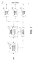
- FIGURE 1 illustrates a print platform with an analyzer that obtains information about its marking engines and/or the content of received jobs to facilitate creating a plan to process the jobs;
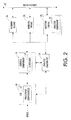
- FIGURE 2 illustrates a print platform in which each marking engine may include an analyzer that obtains information about its health
- FIGURE 3 illustrates a print platform that employs an intelligence component to facilitate determining marking engine health and/or job content
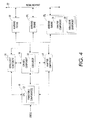
- FIGURE 4 illustrates a print platform in which each marking engine may include an intelligence components that facilitate determining marking engine health
- FIGURE 5 illustrates a print platform with a user interface for manually providing job content and/or marking engine health information
- FIGURE 6 illustrates a method for using marking engine health and/or job content information to facilitate processing jobs with minimal visible defects.
- the print platform can be a multi-purpose platform having capabilities such as printing, scanning, copying, faxing, emailing, etc. simplex and/or duplex pages with color, black and white, highlight color, etc. portions within each side of each page.
- the print platform can include one or more independent modules (e.g., printers) that are interconnected in parallel and/or series to provide concurrent and/or serial processing of one or more jobs.
- Such modules may be independent in that each module is capable of processing a job(s) independently of the other modules.
- Each module can include one or more marking engines, and each marking engine can be associated with similar and/or different attributes (e.g., processing rate, a type(s) of toner, etc).
- the print platform leverages one or more of the attributes, a health (or marking state), etc. of one or more of the marking engines, the content (e.g., location of solid color areas, range of color present, etc.) of jobs to process, characteristics of the print media (e.g., paper weight, size, orientation, etc.), and/or other information to improve image quality and system productivity.
- the content e.g., location of solid color areas, range of color present, etc.
- characteristics of the print media e.g., paper weight, size, orientation, etc.
- other information can be used to minimize the visibility of defects such as streaks, non-uniformities, etc. on each processed page.
- such information can be used to maximize the processing capabilities by minimizing marking engine idle time. It is to be appreciated that such features can be employed prior to, concurrent with, and/or after other known techniques for improving image quality and/or system performance.
- the print platform includes a digital front end (DFE) 10 having one or more processing components 12 that process received print jobs.
- DFE digital front end
- Such jobs can originate from various sources.
- one or more jobs can be obtained from portable storage medium such as CD, DVD, optical disk, Flash memory, stick memory, magnetic tape, floppy disk, etc.
- one or more jobs can be received (via wire or wirelessly) over a bus, a network, or the like from a computer, another print platform, an email server, a facsimile, etc.
- the job can be created via a user interface (not shown) of the print platform.
- Each received job can include one or more pages in which each page can include black and white, highlight color, color, etc. portions, text, graphics, pictures, etc.
- Each of the one or more processing components 12 is capable of determining such content and converting, translating, re-formatting, transforming, etc. one or more of the received jobs into a suitable form (e.g., from RGB, postscript, etc. to CMYK, etc.) for further processing by the print platform.
- a suitable form e.g., from RGB, postscript, etc. to CMYK, etc.
- each of the one or more processing components 12 can include and/or be associated with one or more raster image processors (RIPs), memory, etc.
- RIPs raster image processors
- An analysis component 14 is also able to determine the content of each received file.
- the analysis component 14 can do this through analyzing the received jobs and/or the jobs processed (e.g., converted, etc.) by the one or more processing components 12.
- the analysis component 14 can instruct the one or more processing components 12 to determine such information and convey this information (and the job) to a control component 16 and/or the analysis component 14.
- the analysis component 14 can also convey this information to the control component 16.
- job content analysis can be periodically performed, for example, each time a new job is received, on-demand, at a pre-determined frequency, on the occurrence of an event (e.g., upon a change to a marking engine capability), etc.
- the control component 16 includes a scheduler 18 that determines a strategy for processing the jobs with one or more marking engines 20 1 , 20 2 , ... , 20 N (wherein N is an integer equal to or greater than one).
- the marking engines 20 1 , 20 2 , ..., 20 N are collectively referred to herein as the marking engines 20.
- Each of the marking engines 20 is associated with one or more processing elements such as one or more cleaners, chargers, expose units, developers, photoreceptors, intermediate transfer elements, etc. for reproducing images with similar or different toners (e.g., color, black and white, highlight color, etc.) at similar and/or different processing rates.
- a media highway or path 22 which can be wholly contained within the print platform, distributed amongst different print engines, for example, in a cluster or distributed configuration, etc.
- a media highway or path 22 which can be wholly contained within the print platform, distributed amongst different print engines, for example, in a cluster or distributed configuration, etc.
- forwarded e.g., automatically via the media path 22, manually via a user, etc.
- various other components such as a fuser, a finisher, an output tray, a shredder, etc. for further processing.
- Each of the marking engines 20 is associated with similar and/or different features such as a page per minute processing rate, a type(s) of toner, image resolution, image quality, etc. Such features typically specified through operating ranges and the like.
- a health of each of the marking engines 20 can be determined based on execution of one or more of the features and corresponding operational ranges. For instance, one image quality metric may include determining whether the reproduced image includes visible defects, for example, artifacts such as undesired streaks and/or non-uniformities that are not part of the image. When one or more of the marking engines 20 begin generating images with such defects, those marking engines 20 can be deemed unhealthy. Marking engines 20 that reproduce images without and/or with minimally visible defects can be deemed healthy.
- Other information that can be used to facilitate determining the health of the marking engines 20 includes electrical, optical, and/or mechanical characteristics.
- the analysis component 14 determines the health of each of the marking engines 20. This can be achieved through analyzing the image being marked as various locations such as on a photoreceptor (belt, drum, etc.), an intermediate transfer element, print media, etc. This can also be achieved through measuring and analyzing electrical characteristics (e.g., resistance, impedance, voltage, current, etc.) and/or invoking mechanical components and monitoring their response. In another instance, the analysis component 14 invokes test routines, diagnostic software, etc. that facilitate determining the health of each of the marking engines 20. For example, a diagnostic routine may include sending a test pattern to one or more of the marking engines 20.
- the analysis component 20 can monitor and/or measure various characteristics of the cleaner, the charger, the expose unit, the developer, the photoreceptor, etc.
- the health information is provided to the control component 16 by the analysis component 14 and/or the one or more of the marking engines 20.
- the analysis component 14 can also be used to determine real-time information such as processing load, etc. of each of the marking engines 20 at any moment in time. This information can also be provided to the control component 16.
- the scheduler 20 determines the strategy for processing the jobs with the marking engines 20 and distributes one or more portions of each job to one or more of the marking engines 20 for processing.
- Such strategy can be based on various factors.
- the strategy involves minimizing re-producing images with visible defects such as streaking, non-uniformities, unacceptable color variations, etc.
- the scheduler 18 can leverage the marking engine health and/or the job content information when developing the strategy. Such information can be used to determine which of the marking engines 20 will process which portion of a job.
- a marking engine that introduces defects such as streaks in such area may be by-passed for a marking engine that can mark such areas without introducing streaks.
- the marking engine susceptible to introducing streaks in the solid color area may be selected to process a different portion of the job and/or another job in which the different portion does not include solid color areas.
- the print system can additionally and/or alternatively use other techniques to facilitate reducing the visibility of defects.
- the orientation e.g., rotation and/or translation
- the print media orientation may be changed from long edge feed to short edge feed in order to minimize the visibility of various defects in the final image.
- the marking engine 20 N includes an analysis component 24. Similar to the analysis component 14, the analysis component 24 can facilitate determining the health of its corresponding marking engine 20 N .
- the analysis component 24 can measure and/or monitor image quality (e.g., via scanning and processing), electrical, optical, mechanical, etc. characteristics of the marking engine 20 N and/or invoke test routines and/or diagnostics that facilitate determining the health. Such information can be determined in real-time as the marking engine 20 N is processing a portion of a job, at periodic intervals, and/or upon one or more predetermined events.
- This information can be provided to the control component 16 along with the information obtained by the analysis component 14 (e.g., marking engine health and/or job content) and/or the processing components 12 (e.g., job content).
- the scheduler 18 can then additionally and/or alternatively use the information obtained by the analysis component 24 when creating the plan to process the job.
- each of the marking engines 20 includes its own analysis component 24.
- the analysis component 14 may or may not be included and/or used to determine marking engine health. Rather, each of the marking engines 20 would use its corresponding analysis component and/or an analysis component of another of the marking engines 20 to determine its health. In these instances, the analysis component 14 can simply not be used, used as a back up system, used to capture redundant information, used to valid results, not be included within the print system, etc.
- the system further includes an intelligent component 26 that employ statistics, probabilities, classifiers, neural networks, and the like to facilitate determining, anticipating, predicting, etc. the health of one or more of the marking engines 20 and/or the content of one or more received jobs, and/or creating the plan(s) to process the job(s).
- the intelligent component 26 can interact with the DFE 10, the control component 16, and/or one or more of the marking engines 20.
- the print system optionally can include the analysis component 14 and/or the analysis component 24.
- the intelligent component 26 can monitor image quality, electrical, optical, mechanical, etc. characteristics of each of the marking engines 20. Such data can be compared against similar measurements from healthy, unhealthy, and inoperable marking engines. The results can be tracked and any trends that indicate a marking engine is transitioning from a healthy state to an unhealthy or inoperable state can be identified.
- the print system may send a notification (e.g., a text message, an email, a phone call, a page, a web post, etc.) to a user, a system administrator, a service technician, etc. apprising such individual(s) that one or more of the marking engines may need service and/or replacement.
- the intelligent component 26 can monitor job characteristics such as file size, creator, source, etc., construct patterns based on such information, and use the patterns to anticipate, predict, etc. the content of a newly received job.
- At least one of the marking engines 20 further includes an intelligent component.
- the marking engine 20 N includes an intelligent component 28 and, optionally, the analysis component 24. Similar to the intelligent component 26, the intelligent component 28 can facilitate determining, anticipating, predicting, etc. the health of its marking engines 20 N and/or another of the marking engines 20 through statistics, probabilities, classifiers, neural networks, and the like.
- the print system can also include the analysis component 14.
- each of the marking engines 20 includes its own intelligent component 28.
- the intelligent component 26 may or may not be included and/or used to determine marking engine health. Rather, each of the marking engines 20 would use its corresponding intelligent component 28 and/or an intelligent component 28 of another of the marking engines 20 to determine its health. In these instances, the intelligent component 26 can simply not be used, used as a back up system, used to capture redundant information, used to valid results, not be included within the print system, etc.
- the print systems further includes a user interface 30, which can be used to manually invoke test procedures and/or provide health and/or job content information to the print system.
- the print system can be instructed to process one or more test patterns with one or more of the marking engines 20 and the resultant image(s) can be analyzed off-line.
- the results of the test can then be entered via the user interface 30 and/or other input mechanism (e.g., communications port, etc.).
- the scheduler 18 can leverage this (marking engine health and/or the job content) information when developing the processing strategy to determine which of the marking engines 20 will process which portion of a job in order to minimize the visibility of image quality defects and/or improve productivity through optimally using each of the marking engines 20.
- FIGURE 6 illustrates a method for decreasing the visibility of defects (e.g., streaks, non-uniformities, low color variations, etc.) in the images reproduced by a single or multi-purpose print platform. This is achieved by leveraging knowledge about marking engine health, job content, print media characteristics, and/or other information associated with one or more of components of the print platform. In addition, such information can be used to maximize the processing capabilities by minimizing marking engine idle time.
- defects e.g., streaks, non-uniformities, low color variations, etc.
- the acts and the order of the acts discussed below are not limiting.
- the method can include similar and/or different, more or less, etc. acts in a similar or different order.
- the below method describes determining the content of a job prior to describing determining the health of a marking engine.
- the health can be determined prior to, concurrently with, and/or after the job content, and vice versa.
- a job is received.
- Such job can originate from various sources such as CD, DVD, optical disk, Flash memory, stick memory, magnetic tape, floppy disk, etc., via wire or wirelessly over a bus, a network, or the like, from a computer, another print platform, an email server, a facsimile, etc.
- the content of the job is determined.
- each job can include one or more pages with black and white, highlight color portions, color, etc. portions, and/or text, graphics, pictures, etc.
- Such content can be determined from the received data and/or from data converted, translated, re-formatted, transformed, etc. to a suitable form by one or more raster image processors (RIPs) and/or other processing components.
- RIPs raster image processors
- artificial intelligence or machine learning can be used to facilitate job content.
- the health and/or other information e.g., processing speed, toner type, capabilities, image quality, image resolution, etc.
- the health and/or other information can be determined by a common component that oversees one or more of the marking engines and/or each marking engine can determine its own health. Such components can perform and/or invoke various tests, analyze final images, measure electrical, optical, and/or mechanical functionality, etc.
- artificial intelligence or machine learning can be used to facilitate determining health.
- the content of the job and/or the health of the marking engines are used to create a plan to process the job.
- Such plan may leverage such information to minimize re-producing images with visible defects such as streaking, non-uniformities, low color variations, etc. through selecting which of the marking engines will process which portion of a job.
- Using such information can improve image quality through minimizing the visibility of defects and/or improve productivity and extend marking engine useful life by enabling use of a marking engine that would otherwise be idle due to the defect(s) exhibited by that marking engine.
- the other techniques can be additionally or alternatively employed to facilitate reducing the visibility of defects.
- the orientation e.g., rotation and/or translation
- the print media orientation may be changed from long edge feed to short edge feed in order to minimize the visibility of various defects in the final image.
Landscapes
- Engineering & Computer Science (AREA)
- Theoretical Computer Science (AREA)
- Physics & Mathematics (AREA)
- General Physics & Mathematics (AREA)
- Human Computer Interaction (AREA)
- General Engineering & Computer Science (AREA)
- Microelectronics & Electronic Packaging (AREA)
- Quality & Reliability (AREA)
- Control Or Security For Electrophotography (AREA)
- Accessory Devices And Overall Control Thereof (AREA)
- Facsimiles In General (AREA)
Abstract
Description
- The following relates to print platforms. It finds particular application to selectively distributing portions of a job to one or more marking engines based at least on one or more characteristics of the marking and/or the job. More particularly, it relates to selecting a marking engine, from a plurality of marking engines, to minimize the visibility of marking engine image defects.
- In conventional xerography, an electrostatic latent image is created on the surface of a photoconducting insulator and subsequently transferred to a final receiving substrate or medium. This typically involves the following. An electrostatic charge is deposited on the photoreceptor surface (e.g., by a corona discharge). The photoreceptor is exposed, which selectively dissipates the surface charge in the exposed regions and creates a latent image in the form of an electrostatic charge pattern. The image is developed by transferring electrostatically charged toner particles to the photoreceptor surface. The toner particles are then transferred to a receiving substrate or to one or more intermediate transfer elements and then to the receiving substrate. The transferred image is made permanent by various techniques, including pressure, heat, radiation, solvent, or some combination thereof.
- With conventional multi-marking engine systems (xerographic or other), one or more portions of a print job may be distributed across at least two marking engines. In many instances, one or more of the marking engines may be in an unhealthy state such that the images they reproduce include defects such as streaks, non-uniformities, etc. One technique used to reduce such defects to a negligible level is to not use the marking engine(s) that creates such defects when the job includes portions that are susceptible to the defects exhibited by the marking engine(s). Thus, during the planning phase for a job, the scheduler may simply ignore and/or not consider such marking engine(s). As a consequence, the marking engine(s) remains idle even though it is not inoperative. This can result in reduced availability, throughput, and system productivity.
- In one aspect, a multi-functional multi-engine print platform is illustrated. The print platform includes at least two marking engines that process jobs, a marking engine analyzer that determines image quality defects of the at least two marking engines, and a scheduler that creates a plan to process a job with the at least two marking engines based at least on the image quality defects each of the at least two marking engines in order to minimize visibility of the defects in images reproduced by the at least two marking engine.
- Some examples of print platforms according to the invention will now be described with reference to the accompanying drawings, in which:-
- FIGURE 1 illustrates a print platform with an analyzer that obtains information about its marking engines and/or the content of received jobs to facilitate creating a plan to process the jobs;
- FIGURE 2 illustrates a print platform in which each marking engine may include an analyzer that obtains information about its health;
- FIGURE 3 illustrates a print platform that employs an intelligence component to facilitate determining marking engine health and/or job content;
- FIGURE 4 illustrates a print platform in which each marking engine may include an intelligence components that facilitate determining marking engine health;
- FIGURE 5 illustrates a print platform with a user interface for manually providing job content and/or marking engine health information; and
- FIGURE 6 illustrates a method for using marking engine health and/or job content information to facilitate processing jobs with minimal visible defects.
- With reference to FIGURE 1, a portion of a print platform is illustrated. The print platform can be a multi-purpose platform having capabilities such as printing, scanning, copying, faxing, emailing, etc. simplex and/or duplex pages with color, black and white, highlight color, etc. portions within each side of each page. In addition, the print platform can include one or more independent modules (e.g., printers) that are interconnected in parallel and/or series to provide concurrent and/or serial processing of one or more jobs. Such modules may be independent in that each module is capable of processing a job(s) independently of the other modules. Each module can include one or more marking engines, and each marking engine can be associated with similar and/or different attributes (e.g., processing rate, a type(s) of toner, etc).
- The print platform leverages one or more of the attributes, a health (or marking state), etc. of one or more of the marking engines, the content (e.g., location of solid color areas, range of color present, etc.) of jobs to process, characteristics of the print media (e.g., paper weight, size, orientation, etc.), and/or other information to improve image quality and system productivity. For example, such information can be used to minimize the visibility of defects such as streaks, non-uniformities, etc. on each processed page. In another example, such information can be used to maximize the processing capabilities by minimizing marking engine idle time. It is to be appreciated that such features can be employed prior to, concurrent with, and/or after other known techniques for improving image quality and/or system performance.
- The print platform includes a digital front end (DFE) 10 having one or
more processing components 12 that process received print jobs. Such jobs can originate from various sources. For example, one or more jobs can be obtained from portable storage medium such as CD, DVD, optical disk, Flash memory, stick memory, magnetic tape, floppy disk, etc. In another example, one or more jobs can be received (via wire or wirelessly) over a bus, a network, or the like from a computer, another print platform, an email server, a facsimile, etc. In another example, the job can be created via a user interface (not shown) of the print platform. - Each received job can include one or more pages in which each page can include black and white, highlight color, color, etc. portions, text, graphics, pictures, etc. Each of the one or
more processing components 12 is capable of determining such content and converting, translating, re-formatting, transforming, etc. one or more of the received jobs into a suitable form (e.g., from RGB, postscript, etc. to CMYK, etc.) for further processing by the print platform. In order to facilitate the foregoing, each of the one ormore processing components 12 can include and/or be associated with one or more raster image processors (RIPs), memory, etc. - An
analysis component 14 is also able to determine the content of each received file. Theanalysis component 14 can do this through analyzing the received jobs and/or the jobs processed (e.g., converted, etc.) by the one ormore processing components 12. In addition, theanalysis component 14 can instruct the one ormore processing components 12 to determine such information and convey this information (and the job) to acontrol component 16 and/or theanalysis component 14. Theanalysis component 14 can also convey this information to thecontrol component 16. Such job content analysis can be periodically performed, for example, each time a new job is received, on-demand, at a pre-determined frequency, on the occurrence of an event (e.g., upon a change to a marking engine capability), etc. - The
control component 16 includes ascheduler 18 that determines a strategy for processing the jobs with one ormore marking engines marking engines marking engines 20. Each of themarking engines 20 is associated with one or more processing elements such as one or more cleaners, chargers, expose units, developers, photoreceptors, intermediate transfer elements, etc. for reproducing images with similar or different toners (e.g., color, black and white, highlight color, etc.) at similar and/or different processing rates. Upon processing one or more portions of one or more jobs by one or more of themarking engines 20, those portions are inserted into a media highway or path 22 (which can be wholly contained within the print platform, distributed amongst different print engines, for example, in a cluster or distributed configuration, etc.) and forwarded (e.g., automatically via themedia path 22, manually via a user, etc.) to another one of themarking engines 20 and/or various other components such as a fuser, a finisher, an output tray, a shredder, etc. for further processing. - Each of the
marking engines 20 is associated with similar and/or different features such as a page per minute processing rate, a type(s) of toner, image resolution, image quality, etc. Such features typically specified through operating ranges and the like. A health of each of themarking engines 20 can be determined based on execution of one or more of the features and corresponding operational ranges. For instance, one image quality metric may include determining whether the reproduced image includes visible defects, for example, artifacts such as undesired streaks and/or non-uniformities that are not part of the image. When one or more of themarking engines 20 begin generating images with such defects, those markingengines 20 can be deemed unhealthy.Marking engines 20 that reproduce images without and/or with minimally visible defects can be deemed healthy. The foregoing example is provided for explanatory purposes and is not limiting. Other information that can be used to facilitate determining the health of themarking engines 20 includes electrical, optical, and/or mechanical characteristics. - In one instance, the
analysis component 14 determines the health of each of themarking engines 20. This can be achieved through analyzing the image being marked as various locations such as on a photoreceptor (belt, drum, etc.), an intermediate transfer element, print media, etc. This can also be achieved through measuring and analyzing electrical characteristics (e.g., resistance, impedance, voltage, current, etc.) and/or invoking mechanical components and monitoring their response. In another instance, theanalysis component 14 invokes test routines, diagnostic software, etc. that facilitate determining the health of each of themarking engines 20. For example, a diagnostic routine may include sending a test pattern to one or more of themarking engines 20. Before, during and/or after processing of the test pattern, theanalysis component 20 can monitor and/or measure various characteristics of the cleaner, the charger, the expose unit, the developer, the photoreceptor, etc. The health information is provided to thecontrol component 16 by theanalysis component 14 and/or the one or more of the markingengines 20. Theanalysis component 14 can also be used to determine real-time information such as processing load, etc. of each of the markingengines 20 at any moment in time. This information can also be provided to thecontrol component 16. - As briefly discussed above, the
scheduler 20 determines the strategy for processing the jobs with the markingengines 20 and distributes one or more portions of each job to one or more of the markingengines 20 for processing. Such strategy can be based on various factors. In one non-limiting instance, the strategy involves minimizing re-producing images with visible defects such as streaking, non-uniformities, unacceptable color variations, etc. To achieve such results, thescheduler 18 can leverage the marking engine health and/or the job content information when developing the strategy. Such information can be used to determine which of the markingengines 20 will process which portion of a job. - By way of example, if the job includes a page with a solid color area (e.g., saturated or not), a marking engine that introduces defects such as streaks in such area may be by-passed for a marking engine that can mark such areas without introducing streaks. However, the marking engine susceptible to introducing streaks in the solid color area may be selected to process a different portion of the job and/or another job in which the different portion does not include solid color areas. Thus, using such marking engine and/or job content information can improve image quality through minimizing the visibility of defects and improve productivity and extend marking engine useful life by enabling use of a marking engine that would otherwise be idle due to the system processing a job with content that is sensitive to the defect(s) that are exhibited by that marking engine.
- The print system can additionally and/or alternatively use other techniques to facilitate reducing the visibility of defects. For example, the orientation (e.g., rotation and/or translation) of the image data and/or print media can be suitably changed to minimize the visibility of defects like streaks. For instance, the print media orientation may be changed from long edge feed to short edge feed in order to minimize the visibility of various defects in the final image.
- In FIGURE 2, at least one of the marking
engines 20 optionally includes an analysis component. In this example, the markingengine 20N includes ananalysis component 24. Similar to theanalysis component 14, theanalysis component 24 can facilitate determining the health of its correspondingmarking engine 20N. For example, theanalysis component 24 can measure and/or monitor image quality (e.g., via scanning and processing), electrical, optical, mechanical, etc. characteristics of the markingengine 20N and/or invoke test routines and/or diagnostics that facilitate determining the health. Such information can be determined in real-time as the markingengine 20N is processing a portion of a job, at periodic intervals, and/or upon one or more predetermined events. - This information can be provided to the
control component 16 along with the information obtained by the analysis component 14 (e.g., marking engine health and/or job content) and/or the processing components 12 (e.g., job content). Thescheduler 18 can then additionally and/or alternatively use the information obtained by theanalysis component 24 when creating the plan to process the job. It is to be appreciated that in some instances, each of the markingengines 20 includes itsown analysis component 24. In addition, in these instances, theanalysis component 14 may or may not be included and/or used to determine marking engine health. Rather, each of the markingengines 20 would use its corresponding analysis component and/or an analysis component of another of the markingengines 20 to determine its health. In these instances, theanalysis component 14 can simply not be used, used as a back up system, used to capture redundant information, used to valid results, not be included within the print system, etc. - In FIGURE 3, the system further includes an
intelligent component 26 that employ statistics, probabilities, classifiers, neural networks, and the like to facilitate determining, anticipating, predicting, etc. the health of one or more of the markingengines 20 and/or the content of one or more received jobs, and/or creating the plan(s) to process the job(s). In order to facilitate such, theintelligent component 26 can interact with theDFE 10, thecontrol component 16, and/or one or more of the markingengines 20. The print system optionally can include theanalysis component 14 and/or theanalysis component 24. - For example, the
intelligent component 26 can monitor image quality, electrical, optical, mechanical, etc. characteristics of each of the markingengines 20. Such data can be compared against similar measurements from healthy, unhealthy, and inoperable marking engines. The results can be tracked and any trends that indicate a marking engine is transitioning from a healthy state to an unhealthy or inoperable state can be identified. The print system may send a notification (e.g., a text message, an email, a phone call, a page, a web post, etc.) to a user, a system administrator, a service technician, etc. apprising such individual(s) that one or more of the marking engines may need service and/or replacement. In another example, theintelligent component 26 can monitor job characteristics such as file size, creator, source, etc., construct patterns based on such information, and use the patterns to anticipate, predict, etc. the content of a newly received job. - In FIGURE 4, at least one of the marking
engines 20 further includes an intelligent component. In this example, the markingengine 20N includes anintelligent component 28 and, optionally, theanalysis component 24. Similar to theintelligent component 26, theintelligent component 28 can facilitate determining, anticipating, predicting, etc. the health of its markingengines 20 N and/or another of the markingengines 20 through statistics, probabilities, classifiers, neural networks, and the like. Optionally, the print system can also include theanalysis component 14. - It is to be appreciated that in some instances, each of the marking
engines 20 includes its ownintelligent component 28. In such instances, theintelligent component 26 may or may not be included and/or used to determine marking engine health. Rather, each of the markingengines 20 would use its correspondingintelligent component 28 and/or anintelligent component 28 of another of the markingengines 20 to determine its health. In these instances, theintelligent component 26 can simply not be used, used as a back up system, used to capture redundant information, used to valid results, not be included within the print system, etc. - In FIGURE 5, the print systems further includes a
user interface 30, which can be used to manually invoke test procedures and/or provide health and/or job content information to the print system. Thus, the print system can be instructed to process one or more test patterns with one or more of the markingengines 20 and the resultant image(s) can be analyzed off-line. The results of the test can then be entered via theuser interface 30 and/or other input mechanism (e.g., communications port, etc.). As described above, thescheduler 18 can leverage this (marking engine health and/or the job content) information when developing the processing strategy to determine which of the markingengines 20 will process which portion of a job in order to minimize the visibility of image quality defects and/or improve productivity through optimally using each of the markingengines 20. - FIGURE 6 illustrates a method for decreasing the visibility of defects (e.g., streaks, non-uniformities, low color variations, etc.) in the images reproduced by a single or multi-purpose print platform. This is achieved by leveraging knowledge about marking engine health, job content, print media characteristics, and/or other information associated with one or more of components of the print platform. In addition, such information can be used to maximize the processing capabilities by minimizing marking engine idle time.
- It is to be appreciated that the acts and the order of the acts discussed below are not limiting. Thus, in other instance, the method can include similar and/or different, more or less, etc. acts in a similar or different order. For example, the below method describes determining the content of a job prior to describing determining the health of a marking engine. However, the health can be determined prior to, concurrently with, and/or after the job content, and vice versa.
- At
reference numeral 32, a job is received. Such job can originate from various sources such as CD, DVD, optical disk, Flash memory, stick memory, magnetic tape, floppy disk, etc., via wire or wirelessly over a bus, a network, or the like, from a computer, another print platform, an email server, a facsimile, etc. At 34, the content of the job is determined. For instance, each job can include one or more pages with black and white, highlight color portions, color, etc. portions, and/or text, graphics, pictures, etc. Such content can be determined from the received data and/or from data converted, translated, re-formatted, transformed, etc. to a suitable form by one or more raster image processors (RIPs) and/or other processing components. In addition, artificial intelligence or machine learning can be used to facilitate job content. - At 36, before, during and/or after determining the content of a received job, the health and/or other information (e.g., processing speed, toner type, capabilities, image quality, image resolution, etc.) about one or more of the marking engines of the print system is determined. The health and/or other information can be determined by a common component that oversees one or more of the marking engines and/or each marking engine can determine its own health. Such components can perform and/or invoke various tests, analyze final images, measure electrical, optical, and/or mechanical functionality, etc. In addition, artificial intelligence or machine learning can be used to facilitate determining health.
At 38, the content of the job and/or the health of the marking engines are used to create a plan to process the job. Such plan may leverage such information to minimize re-producing images with visible defects such as streaking, non-uniformities, low color variations, etc. through selecting which of the marking engines will process which portion of a job. Using such information can improve image quality through minimizing the visibility of defects and/or improve productivity and extend marking engine useful life by enabling use of a marking engine that would otherwise be idle due to the defect(s) exhibited by that marking engine. Optionally, the other techniques can be additionally or alternatively employed to facilitate reducing the visibility of defects. For example, the orientation (e.g., rotation and/or translation) of the image data and/or print media can be suitably changed to minimize the visibility of defects like streaks as discussed above. For instance, the print media orientation may be changed from long edge feed to short edge feed in order to minimize the visibility of various defects in the final image.
Claims (11)
- A multi-functional multi-engine print platform, comprising:at least two marking engines (20) that process jobs;a marking engine analyzer (14) that determines image quality defects of the at least two marking engines; anda scheduler (18) that creates a plan to process a job with the at least two marking engines based at least on the image quality defects of each of the at least two marking engines in order to minimize visibility of the defects in images reproduced by the at least two marking engines.
- The multi-functional multi-engine print platform as set forth in claim 1, further including:a digital front end (10) that receives a job for processing by the platform; anda job analyzer that determines a content of the job;wherein the scheduler (18) further bases the plan on the content of the job.
- The multi-functional multi-engine print platform as set forth in claim 2, further including at least one processing component that transforms the job into a format suitable for processing by the at least two marking engines, wherein the content of the job is determined from one or more of the job and the transformed job.
- The multi-functional multi engine print platform as set forth in any of the preceding claims, wherein the scheduler suitably orients at least one of a print media and an image to facilitate minimizing the visibility of the defects in the reproduced image.
- The multi-functional multi-engine print platform as set forth in any of the preceding claims, further including an intelligent component (26) that employs at least one of statistics, probabilities, classifiers, and neural networks to facilitate at least one of determining, anticipating and predicting the image quality defects of the at least two marking engines.
- The multi-functional multi-engine print platform as set forth in claim 5, wherein each of the at least two marking engines includes its own intelligent component (24).
- The multi-functional multi-engine print platform as set forth in any of the preceding claims, wherein the marking engine analyzer (14) determines the image quality defects based on one or more of a predetermined frequency, arrival of a new job to process, a marking engine capability change, and on-demand.
- The multi-functional multi-engine print platform as set forth in claim 7, wherein the marking engine capability change is associated with one or more of a cleaner, a charger, an expose unit, a developer, a photoreceptor, and an intermediate transfer belt associated with the marking engine.
- A method for reducing visibility of marking engine image quality defects, comprising:determining one or more image quality defects of one or more marking engines (2) of a print platform; andproviding portions of a job to the one or more marking engines based on the one or more image quality defects to minimize visibility of the defects in images reproduced by the one or more marking engines.
- The method as set forth in claim 8 or claim 9, further including employing at least one of the image quality defects and the job content to select a marking engine that would otherwise sit idle due to the image quality defects exhibited by the marking engine.
- The method as set forth in claim 9 or claim 10, further including determining the image quality defects based on one or more of a predetermined frequency, arrival of a new job to process, a marking engine capability, and on-demand.
Applications Claiming Priority (1)
| Application Number | Priority Date | Filing Date | Title |
|---|---|---|---|
| US11/403,785 US8330965B2 (en) | 2006-04-13 | 2006-04-13 | Marking engine selection |
Publications (2)
| Publication Number | Publication Date |
|---|---|
| EP1845441A2 true EP1845441A2 (en) | 2007-10-17 |
| EP1845441A3 EP1845441A3 (en) | 2008-09-24 |
Family
ID=38164547
Family Applications (1)
| Application Number | Title | Priority Date | Filing Date |
|---|---|---|---|
| EP07105934A Ceased EP1845441A3 (en) | 2006-04-13 | 2007-04-11 | Marking engine selection |
Country Status (3)
| Country | Link |
|---|---|
| US (1) | US8330965B2 (en) |
| EP (1) | EP1845441A3 (en) |
| JP (1) | JP2007288783A (en) |
Families Citing this family (5)
| Publication number | Priority date | Publication date | Assignee | Title |
|---|---|---|---|---|
| US20080309962A1 (en) * | 2007-06-12 | 2008-12-18 | Xerox Corporation | System and method for content-based alternate imaging |
| US8264704B2 (en) * | 2007-08-29 | 2012-09-11 | Xerox Corporation | Method of automatically controlling print quality in digital printing |
| US8208170B2 (en) | 2008-10-10 | 2012-06-26 | Xerox Corporation | System and method for printing target colors with process colors utilizing parallel feedforward neural networks |
| JP6505155B2 (en) * | 2017-04-24 | 2019-04-24 | キヤノン株式会社 | Motor control device, sheet conveying device, and image forming apparatus |
| JP2026013763A (en) * | 2024-07-17 | 2026-01-29 | 富士フイルムビジネスイノベーション株式会社 | Information processing system and information processing program |
Citations (1)
| Publication number | Priority date | Publication date | Assignee | Title |
|---|---|---|---|---|
| US6606165B1 (en) | 1995-08-07 | 2003-08-12 | T/R Systems, Inc. | Method and apparatus for routing pages to printers in a multi-print engine as a function of print job parameters |
Family Cites Families (77)
| Publication number | Priority date | Publication date | Assignee | Title |
|---|---|---|---|---|
| US4579446A (en) | 1982-07-12 | 1986-04-01 | Canon Kabushiki Kaisha | Both-side recording system |
| US4587532A (en) | 1983-05-02 | 1986-05-06 | Canon Kabushiki Kaisha | Recording apparatus producing multiple copies simultaneously |
| JP2590477B2 (en) | 1987-05-13 | 1997-03-12 | 富士ゼロックス株式会社 | Paper transport direction change device |
| EP0303276B1 (en) | 1987-08-12 | 1994-11-30 | Canon Kabushiki Kaisha | Sheet conveying apparatus and sheet conveying method |
| US4836119A (en) | 1988-03-21 | 1989-06-06 | The Charles Stark Draper Laboratory, Inc. | Sperical ball positioning apparatus for seamed limp material article assembly system |
| JP2636441B2 (en) | 1989-11-09 | 1997-07-30 | 富士ゼロックス株式会社 | Image recording device |
| US5095342A (en) | 1990-09-28 | 1992-03-10 | Xerox Corporation | Methods for sheet scheduling in an imaging system having an endless duplex paper path loop |
| US5080340A (en) | 1991-01-02 | 1992-01-14 | Eastman Kodak Company | Modular finisher for a reproduction apparatus |
| US5159395A (en) | 1991-08-29 | 1992-10-27 | Xerox Corporation | Method of scheduling copy sheets in a dual mode duplex printing system |
| US6036300A (en) * | 1992-02-26 | 2000-03-14 | Canon Kabushiki Kaisha | Method for recording image and apparatus therefor and recorded matter by such an apparatus |
| US5272511A (en) | 1992-04-30 | 1993-12-21 | Xerox Corporation | Sheet inserter and methods of inserting sheets into a continuous stream of sheets |
| US5358238A (en) | 1993-04-27 | 1994-10-25 | Xerox Corporation | Shared user printer output dynamic "mailbox" system |
| US5326093A (en) | 1993-05-24 | 1994-07-05 | Xerox Corporation | Universal interface module interconnecting various copiers and printers with various sheet output processors |
| US5473419A (en) | 1993-11-08 | 1995-12-05 | Eastman Kodak Company | Image forming apparatus having a duplex path with an inverter |
| JP3098664B2 (en) | 1993-12-01 | 2000-10-16 | キヤノン株式会社 | Printing equipment |
| US5596416A (en) * | 1994-01-13 | 1997-01-21 | T/R Systems | Multiple printer module electrophotographic printing device |
| US5525031A (en) | 1994-02-18 | 1996-06-11 | Xerox Corporation | Automated print jobs distribution system for shared user centralized printer |
| US5778377A (en) | 1994-11-04 | 1998-07-07 | International Business Machines Corporation | Table driven graphical user interface |
| US5570172A (en) | 1995-01-18 | 1996-10-29 | Xerox Corporation | Two up high speed printing system |
| US5557367A (en) | 1995-03-27 | 1996-09-17 | Xerox Corporation | Method and apparatus for optimizing scheduling in imaging devices |
| US5489969A (en) | 1995-03-27 | 1996-02-06 | Xerox Corporation | Apparatus and method of controlling interposition of sheet in a stream of imaged substrates |
| US5504568A (en) | 1995-04-21 | 1996-04-02 | Xerox Corporation | Print sequence scheduling system for duplex printing apparatus |
| US5629762A (en) | 1995-06-07 | 1997-05-13 | Eastman Kodak Company | Image forming apparatus having a duplex path and/or an inverter |
| US5710968A (en) | 1995-08-28 | 1998-01-20 | Xerox Corporation | Bypass transport loop sheet insertion system |
| US5568246A (en) | 1995-09-29 | 1996-10-22 | Xerox Corporation | High productivity dual engine simplex and duplex printing system using a reversible duplex path |
| US6493098B1 (en) | 1996-06-05 | 2002-12-10 | John S. Cornell | Desk-top printer and related method for two-sided printing |
| US6476923B1 (en) | 1996-06-05 | 2002-11-05 | John S. Cornell | Tandem printer printing apparatus |
| US6297886B1 (en) | 1996-06-05 | 2001-10-02 | John S. Cornell | Tandem printer printing apparatus |
| US5995721A (en) | 1996-10-18 | 1999-11-30 | Xerox Corporation | Distributed printing system |
| US6059284A (en) | 1997-01-21 | 2000-05-09 | Xerox Corporation | Process, lateral and skew sheet positioning apparatus and method |
| AUPO802297A0 (en) * | 1997-07-15 | 1997-08-07 | Silverbrook Research Pty Ltd | Image processing method and apparatus (ART33) |
| US5884910A (en) | 1997-08-18 | 1999-03-23 | Xerox Corporation | Evenly retractable and self-leveling nips sheets ejection system |
| CA2242500C (en) * | 1997-09-15 | 2007-11-13 | Monarch Marking Systems, Inc. | Early thermal printhead failure prediction system |
| US6210813B1 (en) | 1998-09-02 | 2001-04-03 | Micron Technology, Inc. | Forming metal silicide resistant to subsequent thermal processing |
| US6125248A (en) | 1998-11-30 | 2000-09-26 | Xerox Corporation | Electrostatographic reproduction machine including a plurality of selectable fusing assemblies |
| IT1308720B1 (en) | 1999-06-08 | 2002-01-10 | Tecnau Srl | DYNAMIC SEQUENCER FOR PRINTED SHEETS OF PAPER |
| US6241242B1 (en) | 1999-10-12 | 2001-06-05 | Hewlett-Packard Company | Deskew of print media |
| US6577925B1 (en) | 1999-11-24 | 2003-06-10 | Xerox Corporation | Apparatus and method of distributed object handling |
| US6384918B1 (en) | 1999-11-24 | 2002-05-07 | Xerox Corporation | Spectrophotometer for color printer color control with displacement insensitive optics |
| US7864346B2 (en) | 2000-05-16 | 2011-01-04 | Xerox Corporation | Apparatus and method for describing, planning and automatically programming complex finishing tasks |
| US6550762B2 (en) | 2000-12-05 | 2003-04-22 | Xerox Corporation | High speed printer with dual alternate sheet inverters |
| US6450711B1 (en) | 2000-12-05 | 2002-09-17 | Xerox Corporation | High speed printer with dual alternate sheet inverters |
| US8411298B2 (en) * | 2001-01-11 | 2013-04-02 | Sharp Laboratories Of America, Inc. | Methods and systems for printing device load-balancing |
| US6633790B2 (en) | 2001-01-29 | 2003-10-14 | Xerox Corporation | Systems and methods for optimizing a production facility |
| US6607320B2 (en) | 2001-03-30 | 2003-08-19 | Xerox Corporation | Mobius combination of reversion and return path in a paper transport system |
| US6554276B2 (en) | 2001-03-30 | 2003-04-29 | Xerox Corporation | Flexible sheet reversion using an omni-directional transport system |
| US6621576B2 (en) | 2001-05-22 | 2003-09-16 | Xerox Corporation | Color imager bar based spectrophotometer for color printer color control system |
| US6633382B2 (en) | 2001-05-22 | 2003-10-14 | Xerox Corporation | Angular, azimuthal and displacement insensitive spectrophotometer for color printer color control systems |
| US6639669B2 (en) | 2001-09-10 | 2003-10-28 | Xerox Corporation | Diagnostics for color printer on-line spectrophotometer control system |
| US6608988B2 (en) | 2001-10-18 | 2003-08-19 | Xerox Corporation | Constant inverter speed timing method and apparatus for duplex sheets in a tandem printer |
| US6612571B2 (en) | 2001-12-06 | 2003-09-02 | Xerox Corporation | Sheet conveying device having multiple outputs |
| US6476376B1 (en) | 2002-01-16 | 2002-11-05 | Xerox Corporation | Two dimensional object position sensor |
| US6722751B2 (en) * | 2002-01-30 | 2004-04-20 | Hewlett-Packard Development Company, L.P. | Method to correct for color error caused by malfunctioning ink ejection elements |
| US20040012818A1 (en) * | 2002-07-19 | 2004-01-22 | Bauer Stephen W. | Reducing artifacts in printing |
| US8315898B2 (en) | 2002-10-30 | 2012-11-20 | Palo Alto Research Center, Incorporated | Planning and scheduling reconfigurable systems around off-line resources |
| US7233405B2 (en) | 2002-10-30 | 2007-06-19 | Palo Alto Research Center, Incorporated | Planning and scheduling reconfigurable systems with regular and diagnostic jobs |
| US7230736B2 (en) | 2002-10-30 | 2007-06-12 | Palo Alto Research Center, Incorporated | Planning and scheduling reconfigurable systems with alternative capabilities |
| US6944838B2 (en) | 2003-02-03 | 2005-09-13 | Cadence Design Systems, Inc. | Method and system for design verification using proof-partitioning |
| US20040150156A1 (en) | 2003-02-04 | 2004-08-05 | Palo Alto Research Center, Incorporated. | Frameless media path modules |
| US7093831B2 (en) | 2003-02-04 | 2006-08-22 | Palo Alto Research Center Inc. | Media path modules |
| JP2004287483A (en) * | 2003-03-19 | 2004-10-14 | Fuji Xerox Co Ltd | Method and device for presenting guidance for information processing system, and information processing system |
| US6856845B2 (en) | 2003-04-28 | 2005-02-15 | Palo Alto Research Center Inc. | Monitoring and reporting incremental job status system and method |
| US7139629B2 (en) | 2003-04-28 | 2006-11-21 | Palo Alto Research Center Incorporated | Planning and scheduling for failure recovery system and method |
| US6895292B2 (en) | 2003-04-28 | 2005-05-17 | Palo Alto Research Center Inc. | Predictive and preemptive planning and scheduling for different job priorities system and method |
| US7226049B2 (en) | 2003-06-06 | 2007-06-05 | Xerox Corporation | Universal flexible plural printer to plural finisher sheet integration system |
| US7315700B2 (en) * | 2003-07-09 | 2008-01-01 | Samsung Electronics Co., Ltd. | Image forming apparatus capable of optimum outputting according to the grade of consumables |
| US6819906B1 (en) | 2003-08-29 | 2004-11-16 | Xerox Corporation | Printer output sets compiler to stacker system |
| JP2005184198A (en) * | 2003-12-17 | 2005-07-07 | Ricoh Co Ltd | Image processing device |
| US6973286B2 (en) | 2004-01-21 | 2005-12-06 | Xerox Corporation | High print rate merging and finishing system for parallel printing |
| US20050225586A1 (en) * | 2004-04-08 | 2005-10-13 | Brenner James M | Method and apparatus for mitigating the effects of printer dot placement errors |
| US7206532B2 (en) * | 2004-08-13 | 2007-04-17 | Xerox Corporation | Multiple object sources controlled and/or selected based on a common sensor |
| US7188929B2 (en) | 2004-08-13 | 2007-03-13 | Xerox Corporation | Parallel printing architecture with containerized image marking engines |
| US7493055B2 (en) * | 2006-03-17 | 2009-02-17 | Xerox Corporation | Fault isolation of visible defects with manual module shutdown options |
| US7024152B2 (en) | 2004-08-23 | 2006-04-04 | Xerox Corporation | Printing system with horizontal highway and single pass duplex |
| US7123873B2 (en) | 2004-08-23 | 2006-10-17 | Xerox Corporation | Printing system with inverter disposed for media velocity buffering and registration |
| US7673958B2 (en) * | 2005-06-21 | 2010-03-09 | Hewlett-Packard Development Company, L.P. | Defective imaging element compensation |
| US20090257077A1 (en) * | 2008-04-15 | 2009-10-15 | Xerox Corporation | Defect avoidance in digital printing |
-
2006
- 2006-04-13 US US11/403,785 patent/US8330965B2/en active Active
-
2007
- 2007-04-06 JP JP2007100652A patent/JP2007288783A/en active Pending
- 2007-04-11 EP EP07105934A patent/EP1845441A3/en not_active Ceased
Patent Citations (1)
| Publication number | Priority date | Publication date | Assignee | Title |
|---|---|---|---|---|
| US6606165B1 (en) | 1995-08-07 | 2003-08-12 | T/R Systems, Inc. | Method and apparatus for routing pages to printers in a multi-print engine as a function of print job parameters |
Also Published As
| Publication number | Publication date |
|---|---|
| US8330965B2 (en) | 2012-12-11 |
| JP2007288783A (en) | 2007-11-01 |
| EP1845441A3 (en) | 2008-09-24 |
| US20070242287A1 (en) | 2007-10-18 |
Similar Documents
| Publication | Publication Date | Title |
|---|---|---|
| US7313336B2 (en) | Method and apparatus for image forming capable of effectively recycling toner | |
| US6917437B1 (en) | Resource management for a printing system via job ticket | |
| US5923834A (en) | Machine dedicated monitor, predictor, and diagnostic server | |
| US6744527B1 (en) | User interface for navigation and control of a printing system | |
| JP4515697B2 (en) | Method for paper tray programming | |
| CN102841523A (en) | Image forming apparatus, image forming system and transfer method | |
| US20120086954A1 (en) | Electrophotographic image forming apparatus that selects a screen from a plurality of screens | |
| US6871029B2 (en) | Process for minimizing toner usage in minimum area coverage patches and minimizing toner churning | |
| US6504556B1 (en) | Operator notation tool tip | |
| JP2007288783A (en) | Marking engine selection in print platform | |
| US8711380B2 (en) | Automatic image-content based adjustment of printer printing procedures | |
| US9041971B2 (en) | Image forming apparatus | |
| US6823146B2 (en) | Image forming apparatus and self-diagnosis system | |
| US20060055970A1 (en) | Page buffer management in a printing system | |
| JP2007317207A (en) | Server | |
| EP0895399A1 (en) | Improvements in or relating to servers | |
| JP2004029514A (en) | Image forming device | |
| JP4054410B2 (en) | server | |
| JP7030498B2 (en) | Image forming device, image forming method and program | |
| US20080181649A1 (en) | Method for analyzing print/copy job | |
| US20250208555A1 (en) | Electronic apparatus, anomaly detection system, and anomaly detection method | |
| JP2004170651A (en) | Image forming device | |
| JP3943804B2 (en) | Image forming apparatus | |
| JP2020071410A (en) | Image processing apparatus, image forming apparatus, program, and image processing method | |
| JP2005011117A (en) | Printing command device and printing system |
Legal Events
| Date | Code | Title | Description |
|---|---|---|---|
| PUAI | Public reference made under article 153(3) epc to a published international application that has entered the european phase |
Free format text: ORIGINAL CODE: 0009012 |
|
| AK | Designated contracting states |
Kind code of ref document: A2 Designated state(s): AT BE BG CH CY CZ DE DK EE ES FI FR GB GR HU IE IS IT LI LT LU LV MC MT NL PL PT RO SE SI SK TR |
|
| AX | Request for extension of the european patent |
Extension state: AL BA HR MK YU |
|
| PUAL | Search report despatched |
Free format text: ORIGINAL CODE: 0009013 |
|
| AK | Designated contracting states |
Kind code of ref document: A3 Designated state(s): AT BE BG CH CY CZ DE DK EE ES FI FR GB GR HU IE IS IT LI LT LU LV MC MT NL PL PT RO SE SI SK TR |
|
| AX | Request for extension of the european patent |
Extension state: AL BA HR MK RS |
|
| RIC1 | Information provided on ipc code assigned before grant |
Ipc: G03G 15/00 20060101ALI20080816BHEP Ipc: G06F 3/12 20060101AFI20070627BHEP |
|
| 17P | Request for examination filed |
Effective date: 20090324 |
|
| 17Q | First examination report despatched |
Effective date: 20090423 |
|
| AKX | Designation fees paid |
Designated state(s): DE FR GB |
|
| STAA | Information on the status of an ep patent application or granted ep patent |
Free format text: STATUS: THE APPLICATION HAS BEEN REFUSED |
|
| 18R | Application refused |
Effective date: 20150210 |