EP1845262A2 - Axial flow positive displacement worm pump - Google Patents
Axial flow positive displacement worm pump Download PDFInfo
- Publication number
- EP1845262A2 EP1845262A2 EP07101942A EP07101942A EP1845262A2 EP 1845262 A2 EP1845262 A2 EP 1845262A2 EP 07101942 A EP07101942 A EP 07101942A EP 07101942 A EP07101942 A EP 07101942A EP 1845262 A2 EP1845262 A2 EP 1845262A2
- Authority
- EP
- European Patent Office
- Prior art keywords
- helical blades
- pump
- bodies
- worm pump
- axis
- Prior art date
- Legal status (The legal status is an assumption and is not a legal conclusion. Google has not performed a legal analysis and makes no representation as to the accuracy of the status listed.)
- Withdrawn
Links
- 238000006073 displacement reaction Methods 0.000 title claims abstract description 14
- 239000012530 fluid Substances 0.000 claims description 19
- 238000011144 upstream manufacturing Methods 0.000 claims description 3
- 230000000694 effects Effects 0.000 description 3
- 238000004519 manufacturing process Methods 0.000 description 3
- 238000005086 pumping Methods 0.000 description 3
- 230000003068 static effect Effects 0.000 description 3
- 239000007788 liquid Substances 0.000 description 2
- 238000012986 modification Methods 0.000 description 2
- 230000004048 modification Effects 0.000 description 2
- 230000015556 catabolic process Effects 0.000 description 1
- 238000004891 communication Methods 0.000 description 1
- 238000006731 degradation reaction Methods 0.000 description 1
- 238000012938 design process Methods 0.000 description 1
- 230000003993 interaction Effects 0.000 description 1
- 230000003071 parasitic effect Effects 0.000 description 1
- 238000007789 sealing Methods 0.000 description 1
Images



Classifications
-
- F—MECHANICAL ENGINEERING; LIGHTING; HEATING; WEAPONS; BLASTING
- F04—POSITIVE - DISPLACEMENT MACHINES FOR LIQUIDS; PUMPS FOR LIQUIDS OR ELASTIC FLUIDS
- F04C—ROTARY-PISTON, OR OSCILLATING-PISTON, POSITIVE-DISPLACEMENT MACHINES FOR LIQUIDS; ROTARY-PISTON, OR OSCILLATING-PISTON, POSITIVE-DISPLACEMENT PUMPS
- F04C2/00—Rotary-piston machines or pumps
- F04C2/08—Rotary-piston machines or pumps of intermeshing-engagement type, i.e. with engagement of co-operating members similar to that of toothed gearing
- F04C2/10—Rotary-piston machines or pumps of intermeshing-engagement type, i.e. with engagement of co-operating members similar to that of toothed gearing of internal-axis type with the outer member having more teeth or tooth-equivalents, e.g. rollers, than the inner member
- F04C2/107—Rotary-piston machines or pumps of intermeshing-engagement type, i.e. with engagement of co-operating members similar to that of toothed gearing of internal-axis type with the outer member having more teeth or tooth-equivalents, e.g. rollers, than the inner member with helical teeth
- F04C2/1071—Rotary-piston machines or pumps of intermeshing-engagement type, i.e. with engagement of co-operating members similar to that of toothed gearing of internal-axis type with the outer member having more teeth or tooth-equivalents, e.g. rollers, than the inner member with helical teeth the inner and outer member having a different number of threads and one of the two being made of elastic materials, e.g. Moineau type
-
- F—MECHANICAL ENGINEERING; LIGHTING; HEATING; WEAPONS; BLASTING
- F04—POSITIVE - DISPLACEMENT MACHINES FOR LIQUIDS; PUMPS FOR LIQUIDS OR ELASTIC FLUIDS
- F04C—ROTARY-PISTON, OR OSCILLATING-PISTON, POSITIVE-DISPLACEMENT MACHINES FOR LIQUIDS; ROTARY-PISTON, OR OSCILLATING-PISTON, POSITIVE-DISPLACEMENT PUMPS
- F04C2/00—Rotary-piston machines or pumps
- F04C2/08—Rotary-piston machines or pumps of intermeshing-engagement type, i.e. with engagement of co-operating members similar to that of toothed gearing
- F04C2/082—Details specially related to intermeshing engagement type machines or pumps
- F04C2/084—Toothed wheels
-
- F—MECHANICAL ENGINEERING; LIGHTING; HEATING; WEAPONS; BLASTING
- F04—POSITIVE - DISPLACEMENT MACHINES FOR LIQUIDS; PUMPS FOR LIQUIDS OR ELASTIC FLUIDS
- F04C—ROTARY-PISTON, OR OSCILLATING-PISTON, POSITIVE-DISPLACEMENT MACHINES FOR LIQUIDS; ROTARY-PISTON, OR OSCILLATING-PISTON, POSITIVE-DISPLACEMENT PUMPS
- F04C2/00—Rotary-piston machines or pumps
- F04C2/08—Rotary-piston machines or pumps of intermeshing-engagement type, i.e. with engagement of co-operating members similar to that of toothed gearing
- F04C2/10—Rotary-piston machines or pumps of intermeshing-engagement type, i.e. with engagement of co-operating members similar to that of toothed gearing of internal-axis type with the outer member having more teeth or tooth-equivalents, e.g. rollers, than the inner member
- F04C2/107—Rotary-piston machines or pumps of intermeshing-engagement type, i.e. with engagement of co-operating members similar to that of toothed gearing of internal-axis type with the outer member having more teeth or tooth-equivalents, e.g. rollers, than the inner member with helical teeth
- F04C2/1071—Rotary-piston machines or pumps of intermeshing-engagement type, i.e. with engagement of co-operating members similar to that of toothed gearing of internal-axis type with the outer member having more teeth or tooth-equivalents, e.g. rollers, than the inner member with helical teeth the inner and outer member having a different number of threads and one of the two being made of elastic materials, e.g. Moineau type
- F04C2/1073—Rotary-piston machines or pumps of intermeshing-engagement type, i.e. with engagement of co-operating members similar to that of toothed gearing of internal-axis type with the outer member having more teeth or tooth-equivalents, e.g. rollers, than the inner member with helical teeth the inner and outer member having a different number of threads and one of the two being made of elastic materials, e.g. Moineau type where one member is stationary while the other member rotates and orbits
Definitions
- the present invention relates generally to pumps and, more particularly, to continuous axial flow worm and screw pumps.
- Pumps are widely used in many applications. Pumps have been implemented in a variety of forms, from linear reciprocating pumps, such as are found in household tire pumps and in most automobile engines, to rotary Wankel and gerotor pumps, and axial flow and centrifugal pumps such as exist in modern day turbomachinery.
- Axial flow pumps have a wide range of applications for pumping fluid because of the combination of their ability to provide high mass flow rate for a given frontal area and continuous near steady fluid flow. It is a goal of pump manufacturers to provide light-weight and compact pumps. It is another goal to have as few parts as possible in the pump to reduce the costs of manufacturing, installing, refurbishing, overhauling, and replacing the pump.
- a continuous axial flow positive displacement pump also referred to as a worm pump includes an inlet axially spaced apart and upstream from an outlet.
- a pump assembly includes inner and outer bodies extending from the inlet to the outlet.
- the inner and outer bodies have offset inner and outer axes, respectively.
- the inner and outer bodies have intermeshed inner and outer helical blades wound about inner and outer axes, respectively.
- the inner and outer bodies have inner and outer numbers of the inner and outer helical blades, respectively.
- the outer number of the outer helical blades is one more or one less than the inner number of the inner helical blades.
- the inner and outer helical blades extend radially outwardly and inwardly, respectively. Either or both bodies may be rotatable about their respective axes. If both bodies rotate, then they rotate in the same direction.
- the inner and outer bodies are rotatable about fixed inner and outer axes in inner and outer rotational directions respectively, then the inner and outer bodies are geared together in a fixed gear ratio determined by the ratio of the number of inner helical blades to the number of outer helical blades.
- the outer body is fixed, then the inner body rotates (spins) about the inner body axis while the inner body axis orbits about the outer body axis.
- the number of the outer helical blades is one less than the number of the inner helical blades, then the inner body will spin about the inner body axis in the same direction as the inner body axis orbits about the outer body axis.
- the number of the outer helical blades is one more than the number of the inner helical blades, then the inner body will spin about the inner body axis in the opposite direction to the orbit of the inner body axis about the outer body axis.
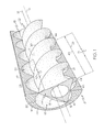
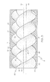
- FIGS. 1 and 2 Illustrated in FIGS. 1 and 2 are first and second exemplary embodiments of a continuous axial flow positive displacement pump also referred to as a worm pump 8.
- the worm pump 8 is designed to pump a fluid such as a gas or a liquid.
- the worm pump 8 includes a pump assembly 15 having inner and outer bodies 12, 14 extending from an inlet 20 to an outlet 22.
- the inner body 12 is disposed within a cavity 19 of the outer body 14.
- the inner and outer bodies 12, 14 have spaced apart parallel inner and outer axes 16, 18, respectively.
- the pump assembly 15 provides continuous flow through the inlet 20 and the outlet 22 during operation of the worm pump 8.
- Either or both bodies may be rotatable about their respective axis. If both bodies are rotatable, they rotate in the same circumferential direction but at different rotational speeds, determined by a fixed relationship. This is illustrated in FIG. 8 by inner and outer body rotational speeds 74, 72.
- the inner and outer bodies 12, 14 are geared together so that they always rotate relative to each other at a fixed speed ratio and phase relationship, as illustrated by the gearing in gearbox 82 in FIGS. 5 and 6.
- the inner body 12 is rotatable about the inner axis 16 within the outer body 14.
- the outer body 14 may be rotatably fixed or rotatable about the outer axis 18.
- the inner and outer bodies 12, 14 have intermeshed inner and outer helical blades 17, 27 wound about the inner and outer axes 16, 18, respectively.
- the inner and outer helical blades 17, 27 have inner and outer helical surfaces 21, 23, respectively.
- the inner helical blades 17 extend radially outwardly from a hollow inner hub 51 of the inner body 12 and the outer helical blades 27 extend radially inwardly from an outer shell 53 of the outer body 14.
- An inner helical edge 47 along the inner helical blade 17 sealingly engages the outer helical surface 23 of the outer helical blade 27 as they rotate relative to each other.
- An outer helical edge 48 along the outer helical blade 27 sealingly engages the inner helical surface 21 of the inner helical blade 17 as they rotate relative to each other.
- the inner and outer bodies 12, 14 have inner and outer body lobes 60, 64 corresponding to the inner and outer helical blades 17, 27, respectively. If the inner body 12 has a number of inner body lobes 60 or inner helical blades 17 designated by N, and illustrated herein as three inner body lobes 60 or inner helical blades 17, then the outer body 14 will have either N-1 or N+1 outer body lobes 64 or outer helical blades 27, as illustrated in FIGS. 7 and 8 for the first and second exemplary embodiments of the pump assembly 15, respectively.
- the first exemplary embodiment of the pump assembly 15 has two (N-1) outer body lobes 64 or outer helical blades 27 and the second exemplary embodiment of the pump assembly 15 has four (N+1) outer body lobes 64 or outer helical blades 27.
- N-1 outer body lobes 64 or outer helical blades 27
- four sealing points 62 between the inner and outer bodies 12, 14 are illustrated in FIG. 7 but that five periodically overlapping seals exist between the inner and outer helical blades 17, 27 along the entire length of the inner and outer bodies 12, 14. It is the interaction of these seals that serves to continually form and isolate chambers of fluid within the device.
- FIGS. 9 and 10 illustrate a fixed outer body 14 and thus the inner body 12 orbits about the outer axis 18.
- the inner body 12 in both FIGS. has three inner helical blades 17 designated by N.
- the outer body 14 in FIGS. 9 and 10 has two or in general N-1 outer helical blades 27 and therefore orbits in a direction W, which is the same as the inner rotational direction RDI that the inner body 12 takes about the inner axis.
- the outer body 14 illustrated in FIG. 11 has four or in general N+1 outer helical blades 27 and therefore orbits in a direction W, which is opposite to the inner rotational direction RDI that the inner body 12 takes about the inner axis.
- the outer body is rotatably fixed, then the magnitude of the inner body spin angular displacement is related to the inner body orbital angular displacement by the inverse of the number of inner body lobes. Consequently, the spin and orbital rates are also related by this factor. If the outer body is rotatable about the outer body axis, then the inner body rotates in the same direction, about the inner body axis, at an angular relationship given by the ratio of the number of outer body lobes to the number of inner body lobes.
- the inner and outer helical blades 17, 27 have unique, but constant inner and outer body twist slopes AI and AO respectively.
- a twist slope such as the inner body twist slope AI, is defined as the amount of rotation of a cross-section 41 of the helical element (such as the triangularly-shaped inner body cross-section 68 illustrated in FIGS. 7 and 8) per distance along an axis such as the inner axis 16 as illustrated in FIG. 1. Illustrated in FIG. 1 is 600 degrees of rotation of the inner body cross-section 41.
- a twist slope is also 360 degrees or 2Pi radians divided by an axial distance CD between two successive crests 44 along the same inner or outer helical edges 47, 48 of the helical element such as the inner or outer helical blades 17, 27 as illustrated in FIG. 1.
- the axial distance CD is the distance required for one full turn 43 of the helix.
- a first ratio of the outer body twist slope AO to the inner body twist slope AI is equal to a second ratio of the number of the inner helical blades 17 blades to the number of the outer helical blades 27.
- the number of turns 43 of the helical blades is sufficient to mechanically capture the charges of fluid 50, where mechanical capture is signified by a charge 50 of fluid being closed off from the inlet 20 at an upstream end 52 of the charge 50 before it is discharged through the outlet 22 at a downstream end 54 of the charge 50.
- the first and second exemplary embodiments of the pump assembly 15 require 600 and 480 degrees of inner body twist, respectively, to mechanically capture fluid charges 50 and ensure that the inlet and outlet are not allowed to communicate.
- the twist slopes of the outer body 14 are equal to the twist slopes of the inner body 12 times the number of inner body lobes N divided by the number of outer body lobes M.
- 900 degrees of rotation of the outer body 14 and 600 degrees of rotation of the inner body 12 are required to mechanically capture a charge of fluid 50.
- the displacement of fluid is accomplished by rotating either one or both of the inner and outer bodies. As the body or bodies rotate, charges of fluid are captured at the inlet in the volume between the inner and outer bodies and displaced axially aft.
- the charge of fluid is closed off from communication with the inlet and allowed to communicate with the outlet.
- the physical flow through the pump is then determined by the inlet boundary conditions and the rotational speed of the bodies. If flow restrictions downstream of the pump are such that the outlet pressure is higher than the inlet pressure, shaft work above and beyond parasitic loading will be required to drive the pump. Alternatively, if the outlet pressure is lower than the inlet pressure, shaft work can be extracted from the pump.
- one of the inner and outer bodies may be rotatably fixed and does not rotate or spin about its axis. If the inner or outer body is fixed, then the orbit 76 and spin rotations of the moving body is geared together.
- the inner body 12 is cranked relative to the outer axis 18 so that as it spins about the inner axis 16, the inner axis 16 orbits about the outer axis 18 as illustrated in FIGS. 9 and 10.
- the inner body 12 is illustrated as having been rotated about the inner axis 16 from its position in FIG. 9 to its position in FIG. 10 by 30 degrees and the inner axis 16 is illustrated as having orbited about the outer axis 18 by 90 degrees.
- the continuous axial flow positive displacement pump referred to herein as a worm pump 8
- a worm pump 8 may be used in a wide range of applications and is expected to provide high mass flow rate for a given frontal area and, continuous near steady fluid flow. It is also expected to be light-weight and require fewer parts than other axial pumps, which in turn offers the potential to reduce the costs of manufacturing, installing, refurbishing, overhauling, and replacing the pump.
- the first embodiment provides a first mode of the pump's operation disclosed herein in which the inner and outer bodies 12, 14 both rotate about the inner and outer axes 16, 18, respectively. The first mode avoids introducing a centrifugal rotor whirl effect on pump supports. It also allows fluid to pass axially through the device in a bulk sense, without introducing a swirl component.
- the outer body 14 remains static or fixed and the inner body 12 simultaneously orbits the outer body's geometric center which is the outer axis 18 and spins about the instantaneous inner body's geometric center which is the inner axis 16.
- the static embodiment provides a second mode of the pump operation disclosed in which there is only a single rotor rotating, potentially simplifying the mechanical design process. This mode introduces a swirl component into the fluid as it is displaced through the device which must be accounted for by surrounding components.
- the continuous axial flow positive displacement pump referred to herein as a worm pump 8
- a worm pump 8 may be used in a wide range of applications and is expected to provide reasonably high mass flow rate for a given frontal area and continuous near steady fluid flow.
- pressure ratio is substantially independent of speed over a wide speed range.
- the flow is directly proportional to speed over the same speed range. It is desirable to have this independence of pressure ratio with speed as compared to a conventional pump pressure ratio that is more or less tied directly to speed.
- the worm pump will provide pumping flow rates that are nearly independent of pressure ratio over a wide operating range as compared to conventional fluid dynamics based axial flow pumps, for which pumping rates or levels are indirectly related to pump pressure ratio.
- Steady flow positive displacement operation is also expected to reduce or eliminate cavitation effects in liquid applications, which allows the pump to be run off-design with the only ill effect being a minor degradation of efficiency.
- the worm pump is expected to be light-weight and have far fewer parts than other axial pumps which in turn offers the potential to reduce the costs of manufacturing, installing, refurbishing, overhauling, and replacing the pump.
Landscapes
- Engineering & Computer Science (AREA)
- Mechanical Engineering (AREA)
- General Engineering & Computer Science (AREA)
- Structures Of Non-Positive Displacement Pumps (AREA)
- Rotary Pumps (AREA)
- Details And Applications Of Rotary Liquid Pumps (AREA)
Abstract
An axial flow positive displacement worm pump (8) has a pump assembly (15) including inner and outer bodies (12, 14) having offset inner and outer axes (16, 18) respectively extending from an inlet (20) to an outlet (22). At least one of the bodies is rotatable about its axis. The inner and outer bodies (12, 14) have intermeshed inner and outer helical blades (17, 27) wound about the inner and outer axes (16, 18) respectively. The inner and outer helical blades (17, 27) extend radially outwardly and inwardly respectively. One of inner and outer numbers of the inner and outer helical blades (17, 27) respectively is two or more. The number of the outer helical blades (27) is one more or one less than the number of the inner helical blades (17). The inner and outer bodies (12, 14) may both be rotatable about the inner and outer axes (16, 18) respectively in same inner and outer rotational directions (RDI, RDO) respectively and geared together in a fixed gear ratio.
Description
- The present invention relates generally to pumps and, more particularly, to continuous axial flow worm and screw pumps.
- Pumps are widely used in many applications. Pumps have been implemented in a variety of forms, from linear reciprocating pumps, such as are found in household tire pumps and in most automobile engines, to rotary Wankel and gerotor pumps, and axial flow and centrifugal pumps such as exist in modern day turbomachinery. Axial flow pumps have a wide range of applications for pumping fluid because of the combination of their ability to provide high mass flow rate for a given frontal area and continuous near steady fluid flow. It is a goal of pump manufacturers to provide light-weight and compact pumps. It is another goal to have as few parts as possible in the pump to reduce the costs of manufacturing, installing, refurbishing, overhauling, and replacing the pump.
- A continuous axial flow positive displacement pump also referred to as a worm pump includes an inlet axially spaced apart and upstream from an outlet. A pump assembly includes inner and outer bodies extending from the inlet to the outlet. The inner and outer bodies have offset inner and outer axes, respectively. The inner and outer bodies have intermeshed inner and outer helical blades wound about inner and outer axes, respectively. The inner and outer bodies have inner and outer numbers of the inner and outer helical blades, respectively. The outer number of the outer helical blades is one more or one less than the inner number of the inner helical blades. The inner and outer helical blades extend radially outwardly and inwardly, respectively. Either or both bodies may be rotatable about their respective axes. If both bodies rotate, then they rotate in the same direction.
- If the inner and outer bodies are rotatable about fixed inner and outer axes in inner and outer rotational directions respectively, then the inner and outer bodies are geared together in a fixed gear ratio determined by the ratio of the number of inner helical blades to the number of outer helical blades. If the outer body is fixed, then the inner body rotates (spins) about the inner body axis while the inner body axis orbits about the outer body axis. If the number of the outer helical blades is one less than the number of the inner helical blades, then the inner body will spin about the inner body axis in the same direction as the inner body axis orbits about the outer body axis. If the number of the outer helical blades is one more than the number of the inner helical blades, then the inner body will spin about the inner body axis in the opposite direction to the orbit of the inner body axis about the outer body axis.
- Embodiments of the present invention will now be described, by way of example only, with reference to the accompanying drawings, in which:
- FIG. 1 is a partially cut-away perspective view illustration of helical blade portions of inner and outer bodies of a first exemplary positive displacement continuous axial flow pump.
- FIG. 2 is a partially cut-away perspective view illustration of helical blade portions of inner and outer bodies of a second exemplary positive displacement continuous axial flow pump.
- FIG. 3 is a side view illustration of the pump illustrated in FIG. 1.
- FIG. 4 is a side view illustration of the pump illustrated in FIG. 2.
- FIG. 5 is a side view illustration of gearing between inner and outer bodies of the pump illustrated in FIGS. 1 and 3.
- FIG. 6 is a side view illustration of gearing between inner and outer bodies of the pump illustrated in FIGS. 2 and 4.
- FIG. 7 is a diagrammatic cross-sectional view illustration of the inner and outer body configuration taken through 7-7 in FIG. 5.
- FIG. 8 is a diagrammatic cross-sectional view illustration of the inner and outer body configuration taken through 8-8 in FIG. 6.
- FIG. 9 is a diagrammatic cross-sectional view illustration of the inner and outer body configuration illustrated in FIG. 7 with a fixed non-rotatable outer body.
- FIG. 10 is a diagrammatic cross-sectional view illustration of the inner and outer body configuration illustrated in FIG. 9 with the inner body orbited about 90 degrees.
- FIG. 11 is a diagrammatic cross-sectional view illustration of the inner and outer body configuration illustrated in FIG. 8 with the outer body rotatably fixed.
- Illustrated in FIGS. 1 and 2 are first and second exemplary embodiments of a continuous axial flow positive displacement pump also referred to as a
worm pump 8. Theworm pump 8 is designed to pump a fluid such as a gas or a liquid. Referring to FIGS. 1-6, theworm pump 8 includes apump assembly 15 having inner andouter bodies inlet 20 to anoutlet 22. Theinner body 12 is disposed within acavity 19 of theouter body 14. The inner andouter bodies outer axes pump assembly 15 provides continuous flow through theinlet 20 and theoutlet 22 during operation of theworm pump 8. - Individual charges of
fluid 50 are captured in and by thepump assembly 15 before being discharged at theoutlet 22. Either or both bodies may be rotatable about their respective axis. If both bodies are rotatable, they rotate in the same circumferential direction but at different rotational speeds, determined by a fixed relationship. This is illustrated in FIG. 8 by inner and outer bodyrotational speeds outer bodies gearbox 82 in FIGS. 5 and 6. In the embodiments of thepump 8 illustrated herein theinner body 12 is rotatable about theinner axis 16 within theouter body 14. Theouter body 14 may be rotatably fixed or rotatable about theouter axis 18. - The inner and
outer bodies helical blades outer axes helical blades helical surfaces helical blades 17 extend radially outwardly from a hollowinner hub 51 of theinner body 12 and the outerhelical blades 27 extend radially inwardly from anouter shell 53 of theouter body 14. An innerhelical edge 47 along the innerhelical blade 17 sealingly engages the outerhelical surface 23 of the outerhelical blade 27 as they rotate relative to each other. An outerhelical edge 48 along the outerhelical blade 27 sealingly engages the innerhelical surface 21 of the innerhelical blade 17 as they rotate relative to each other. - Referring to FIGS. 7 and 8, the inner and
outer bodies outer body lobes helical blades inner body 12 has a number ofinner body lobes 60 or innerhelical blades 17 designated by N, and illustrated herein as threeinner body lobes 60 or innerhelical blades 17, then theouter body 14 will have either N-1 or N+1outer body lobes 64 or outerhelical blades 27, as illustrated in FIGS. 7 and 8 for the first and second exemplary embodiments of thepump assembly 15, respectively. Thus, the first exemplary embodiment of thepump assembly 15 has two (N-1)outer body lobes 64 or outerhelical blades 27 and the second exemplary embodiment of thepump assembly 15 has four (N+1)outer body lobes 64 or outerhelical blades 27. Note that foursealing points 62 between the inner andouter bodies helical blades outer bodies - FIGS. 9 and 10 illustrate a fixed
outer body 14 and thus theinner body 12 orbits about theouter axis 18. Theinner body 12 in both FIGS. has three innerhelical blades 17 designated by N. Theouter body 14 in FIGS. 9 and 10 has two or in general N-1 outerhelical blades 27 and therefore orbits in a direction W, which is the same as the inner rotational direction RDI that theinner body 12 takes about the inner axis. Theouter body 14 illustrated in FIG. 11 has four or in general N+1 outerhelical blades 27 and therefore orbits in a direction W, which is opposite to the inner rotational direction RDI that theinner body 12 takes about the inner axis. If the outer body is rotatably fixed, then the magnitude of the inner body spin angular displacement is related to the inner body orbital angular displacement by the inverse of the number of inner body lobes. Consequently, the spin and orbital rates are also related by this factor. If the outer body is rotatable about the outer body axis, then the inner body rotates in the same direction, about the inner body axis, at an angular relationship given by the ratio of the number of outer body lobes to the number of inner body lobes. - Referring to FIG. 1, the inner and outer
helical blades cross-section 41 of the helical element (such as the triangularly-shapedinner body cross-section 68 illustrated in FIGS. 7 and 8) per distance along an axis such as theinner axis 16 as illustrated in FIG. 1. Illustrated in FIG. 1 is 600 degrees of rotation of theinner body cross-section 41. A twist slope is also 360 degrees or 2Pi radians divided by an axial distance CD between twosuccessive crests 44 along the same inner or outerhelical edges helical blades full turn 43 of the helix. A first ratio of the outer body twist slope AO to the inner body twist slope AI is equal to a second ratio of the number of the innerhelical blades 17 blades to the number of the outerhelical blades 27. - The number of
turns 43 of the helical blades is sufficient to mechanically capture the charges offluid 50, where mechanical capture is signified by acharge 50 of fluid being closed off from theinlet 20 at anupstream end 52 of thecharge 50 before it is discharged through theoutlet 22 at adownstream end 54 of thecharge 50. The first and second exemplary embodiments of thepump assembly 15 require 600 and 480 degrees of inner body twist, respectively, to mechanically capturefluid charges 50 and ensure that the inlet and outlet are not allowed to communicate. - The twist slopes of the
outer body 14 are equal to the twist slopes of theinner body 12 times the number of inner body lobes N divided by the number of outer body lobes M. For the configuration illustrated in FIG. 7 having three inner lobes or innerhelical blades 17 and two outer lobes or outerhelical blades 27, 900 degrees of rotation of theouter body 14 and 600 degrees of rotation of theinner body 12 are required to mechanically capture a charge offluid 50. The displacement of fluid is accomplished by rotating either one or both of the inner and outer bodies. As the body or bodies rotate, charges of fluid are captured at the inlet in the volume between the inner and outer bodies and displaced axially aft. Following sufficient rotation, the charge of fluid is closed off from communication with the inlet and allowed to communicate with the outlet. The physical flow through the pump is then determined by the inlet boundary conditions and the rotational speed of the bodies. If flow restrictions downstream of the pump are such that the outlet pressure is higher than the inlet pressure, shaft work above and beyond parasitic loading will be required to drive the pump. Alternatively, if the outlet pressure is lower than the inlet pressure, shaft work can be extracted from the pump. - As described above, one of the inner and outer bodies may be rotatably fixed and does not rotate or spin about its axis. If the inner or outer body is fixed, then the
orbit 76 and spin rotations of the moving body is geared together. For a rotatably fixedouter body 14 embodiment, theinner body 12 is cranked relative to theouter axis 18 so that as it spins about theinner axis 16, theinner axis 16 orbits about theouter axis 18 as illustrated in FIGS. 9 and 10. Theinner body 12 is illustrated as having been rotated about theinner axis 16 from its position in FIG. 9 to its position in FIG. 10 by 30 degrees and theinner axis 16 is illustrated as having orbited about theouter axis 18 by 90 degrees. - The continuous axial flow positive displacement pump, referred to herein as a
worm pump 8, may be used in a wide range of applications and is expected to provide high mass flow rate for a given frontal area and, continuous near steady fluid flow. It is also expected to be light-weight and require fewer parts than other axial pumps, which in turn offers the potential to reduce the costs of manufacturing, installing, refurbishing, overhauling, and replacing the pump. The first embodiment provides a first mode of the pump's operation disclosed herein in which the inner andouter bodies outer axes - In a static outer body embodiment, the
outer body 14 remains static or fixed and theinner body 12 simultaneously orbits the outer body's geometric center which is theouter axis 18 and spins about the instantaneous inner body's geometric center which is theinner axis 16. The static embodiment provides a second mode of the pump operation disclosed in which there is only a single rotor rotating, potentially simplifying the mechanical design process. This mode introduces a swirl component into the fluid as it is displaced through the device which must be accounted for by surrounding components. - The continuous axial flow positive displacement pump, referred to herein as a
worm pump 8, may be used in a wide range of applications and is expected to provide reasonably high mass flow rate for a given frontal area and continuous near steady fluid flow. Because the worm pump operates in a positive displacement mode, pressure ratio is substantially independent of speed over a wide speed range. The flow is directly proportional to speed over the same speed range. It is desirable to have this independence of pressure ratio with speed as compared to a conventional pump pressure ratio that is more or less tied directly to speed. The worm pump will provide pumping flow rates that are nearly independent of pressure ratio over a wide operating range as compared to conventional fluid dynamics based axial flow pumps, for which pumping rates or levels are indirectly related to pump pressure ratio. Steady flow positive displacement operation is also expected to reduce or eliminate cavitation effects in liquid applications, which allows the pump to be run off-design with the only ill effect being a minor degradation of efficiency. The worm pump is expected to be light-weight and have far fewer parts than other axial pumps which in turn offers the potential to reduce the costs of manufacturing, installing, refurbishing, overhauling, and replacing the pump. - While there have been described herein what are considered to be preferred and exemplary embodiments of the present invention, other modifications of the invention shall be apparent to those skilled in the art from the teachings herein and, it is therefore, desired to be secured in the appended claims all such modifications as fall within the true spirit and scope of the invention. Accordingly, what is desired to be secured by Letters Patent is the invention as defined and differentiated in the following claims.
Claims (10)
- An axial flow positive displacement worm pump (8) comprising:an inlet (20) axially spaced apart and upstream from an outlet (22),a pump assembly (15) including an inner body (12) disposed within an outer body (14) and the inner and outer bodies extending from the inlet to the outlet,the inner and outer bodies (12, 14) having offset inner and outer axes (16, 18) respectively,at least one of the inner and outer bodies (12, 14) being rotatable about a corresponding one of the inner and outer axes (16, 18),the inner and outer bodies (12, 14) having intermeshed inner and outer helical blades (17, 27) wound about the inner and outer axes (16, 18) respectively,the inner and outer helical blades (17, 27) extending radially outwardly and inwardly respectively,the inner and outer bodies (12, 14) have inner and outer numbers of inner and outer helical blades (17, 27) respectively, andone of the inner and outer numbers of the inner and outer helical blades (17, 27) respectively is two or more.
- A worm pump (8) as claimed in claim 1 further comprising the number of outer helical blades (27) is one more or one less than the number of inner helical blades (17).
- A worm pump (8) as claimed in claim 1 further comprising the helical blades having sufficient number of turns (43) to trap charges of fluid (50) in the pump assembly (15) during the pump's operation.
- A worm pump (8) as claimed in claim 3 further comprising the number of turns (43) being sufficient to mechanically trap the charges of fluid (50).
- A worm pump (8) as claimed in claim 1 further comprising the inner and outer bodies (12, 14) being rotatable about the inner and outer axes (16, 18) respectively in the same inner and outer rotational directions (RDI, RDO) respectively.
- A worm pump (8) as claimed in any one of the preceding claims, further comprising the inner and outer bodies (12, 14) being geared together in a fixed gear ratio.
- A worm pump (8) as claimed in any one of the preceding claims, further comprising the number of outer helical blades (27) is one less than the number of the inner helical blades (17) and the inner body (12) is operable to orbit about the outer axis (18) in an orbital direction (W) same as the inner rotational direction (RDI).
- A worm pump (8) as claimed in any one of the preceding claims, further comprising the number of outer helical blades (27) is one more than the number of the inner helical blades (17) and the inner body (12) is operable to orbit about the outer axis (18) in an orbital direction (W) opposite the inner rotational direction (RDI).
- A worm pump (8) as claimed in claim 1 further comprising the inner and outer twist slopes (AI, AO) of the inner and outer helical blades (17, 27) respectively, and a first ratio of the outer twist slope (AO) to the inner twist slope (AI) equal to a second ratio of the inner number of the inner helical blades (17) on the inner body (12) to the outer number of the outer helical blades (27) on the outer body (14).
- A worm pump (8) as claimed in claim 1 further comprising the outer body (14) being rotatably fixed about the outer axis (18) and the inner body (12) being orbital about the outer axis (18).
Applications Claiming Priority (1)
| Application Number | Priority Date | Filing Date | Title |
|---|---|---|---|
| US11/401,008 US20070237642A1 (en) | 2006-04-10 | 2006-04-10 | Axial flow positive displacement worm pump |
Publications (1)
| Publication Number | Publication Date |
|---|---|
| EP1845262A2 true EP1845262A2 (en) | 2007-10-17 |
Family
ID=38283209
Family Applications (1)
| Application Number | Title | Priority Date | Filing Date |
|---|---|---|---|
| EP07101942A Withdrawn EP1845262A2 (en) | 2006-04-10 | 2007-02-08 | Axial flow positive displacement worm pump |
Country Status (6)
| Country | Link |
|---|---|
| US (1) | US20070237642A1 (en) |
| EP (1) | EP1845262A2 (en) |
| JP (1) | JP2007278276A (en) |
| CN (1) | CN101054972A (en) |
| CA (1) | CA2576684A1 (en) |
| RU (1) | RU2007105077A (en) |
Cited By (2)
| Publication number | Priority date | Publication date | Assignee | Title |
|---|---|---|---|---|
| DE102010051335A1 (en) * | 2010-11-13 | 2012-05-16 | Artemis Kautschuk- Und Kunststoff-Technik Gmbh | Stator of an eccentric screw pump |
| DE102013109829A1 (en) * | 2013-09-09 | 2015-03-12 | Netzsch Pumpen & Systeme Gmbh | Eccentric screw pump for conveying liquid and / or granular media comprising a stator with elastic lining |
Families Citing this family (5)
| Publication number | Priority date | Publication date | Assignee | Title |
|---|---|---|---|---|
| US7854111B2 (en) * | 2008-03-07 | 2010-12-21 | General Electric Company | Axial flow positive displacement turbine |
| CN104772888B (en) * | 2015-04-02 | 2017-03-01 | 沈阳化工大学 | A kind of extruder screw with internal and external screw |
| CN108121838B (en) * | 2016-11-30 | 2021-09-21 | 中国航发商用航空发动机有限责任公司 | Impeller edge line matching method and device |
| CN109139539A (en) * | 2017-06-28 | 2019-01-04 | 天津手拉手新能源科技有限公司 | A kind of spiral shell cup |
| CN108087037B (en) * | 2018-01-22 | 2023-05-05 | 中国石油大学(华东) | Closed double-screw expander power generation device |
Family Cites Families (35)
| Publication number | Priority date | Publication date | Assignee | Title |
|---|---|---|---|---|
| US1892217A (en) * | 1930-05-13 | 1932-12-27 | Moineau Rene Joseph Louis | Gear mechanism |
| US2553548A (en) * | 1945-08-14 | 1951-05-22 | Henry D Canazzi | Rotary internal-combustion engine of the helical piston type |
| US3168049A (en) * | 1961-09-26 | 1965-02-02 | Mono Pumps Africa Pty | Helical gear pumps |
| FR1586832A (en) * | 1968-02-08 | 1970-03-06 | ||
| SE390751B (en) * | 1973-07-20 | 1977-01-17 | Atlas Copco Ab | SCREWDRIVER |
| SE384720B (en) * | 1974-04-22 | 1976-05-17 | E Larsson | SCREW PUMP AND WAY TO MANUFACTURE THE SAME |
| US4144001A (en) * | 1977-03-29 | 1979-03-13 | Fordertechnik Streicher Gmbh | Eccentric worm pump with annular wearing elements |
| US4179250A (en) * | 1977-11-04 | 1979-12-18 | Chicago Pneumatic Tool Company | Thread construction for rotary worm compression-expansion machines |
| HU175810B (en) * | 1977-12-28 | 1980-10-28 | Orszagos Koolaj Gazipari | Axial-flow multiple-purpose flow apparatus |
| US4500259A (en) * | 1981-08-18 | 1985-02-19 | Schumacher Berthold W | Fluid flow energy converter |
| KR850004305A (en) * | 1983-12-28 | 1985-07-11 | 오노 쓰네오 | Rotary Displacement Eccentric Archimedes Principle Screw Pump |
| EP0169682B1 (en) * | 1984-07-13 | 1991-06-05 | John Leishman Sneddon | Fluid machine |
| US4862359A (en) * | 1984-08-31 | 1989-08-29 | Bio-Logic Systems Corporation | Topographical mapping of brain functionality from neuropsychological test results |
| US4802827A (en) * | 1986-12-24 | 1989-02-07 | Kabushiki Kaisha Toshiba | Compressor |
| US4818197A (en) * | 1987-01-20 | 1989-04-04 | Halliburton Company | Progessive cavity pump |
| US4862357A (en) * | 1987-01-28 | 1989-08-29 | Systemone Holdings, Inc. | Computer reservation system with means to rank travel itineraries chosen in terms of schedule/fare data |
| US5195882A (en) * | 1990-05-12 | 1993-03-23 | Concentric Pumps Limited | Gerotor pump having spiral lobes |
| DK174039B1 (en) * | 1992-05-14 | 2002-05-06 | Cfs Slagelse As | Snail pump for viscous and / or lubricating media, e.g. meat. |
| DE19501441C1 (en) * | 1995-01-19 | 1996-04-04 | Seepex Seeberger Gmbh & Co | Multi=flow eccentric screw pump |
| GB2301632B (en) * | 1995-03-18 | 1998-06-24 | Rolls Royce Plc | Aircraft compound cycle propulsion engine |
| SE9501118L (en) * | 1995-03-29 | 1996-09-30 | Ulf Nordin | Screw press and outlet part for screw press |
| US6217304B1 (en) * | 1995-10-30 | 2001-04-17 | David N. Shaw | Multi-rotor helical-screw compressor |
| US5605124A (en) * | 1995-11-06 | 1997-02-25 | Morgan; Christopher K. | Rotary screw internal combustion engine |
| DE19813999C1 (en) * | 1998-03-28 | 1999-11-25 | Seepex Seeberger Gmbh & Co | Eccentric screw pump |
| DE19924616C2 (en) * | 1999-05-28 | 2001-04-19 | Bornemann J H Gmbh | Process for the production of rotors |
| RU2205274C2 (en) * | 2000-10-19 | 2003-05-27 | Дидин Александр Владимирович | Positive-displacement rotary mchine |
| DE10118785A1 (en) * | 2001-04-17 | 2002-10-24 | Viscotec Pumpen Und Dosiertech | Eccentric screw conveyor pump has at least one screw conveyor in region of intermediate cavity |
| US6905319B2 (en) * | 2002-01-29 | 2005-06-14 | Halliburton Energy Services, Inc. | Stator for down hole drilling motor |
| GB0210018D0 (en) * | 2002-05-01 | 2002-06-12 | Univ City | Plural-screw machines |
| US6705849B2 (en) * | 2002-07-22 | 2004-03-16 | Carrier Corporation | Discharge porting design for screw compressor |
| US6651433B1 (en) * | 2002-09-13 | 2003-11-25 | Leslie C. George, Jr. | Brayton screw engine with brayton bottoming system |
| EP1567770B1 (en) * | 2002-12-03 | 2017-01-18 | BITZER Kühlmaschinenbau GmbH | Screw compressor |
| RU2228444C1 (en) * | 2003-03-25 | 2004-05-10 | Общество с ограниченной ответственностью фирма "Радиус-Сервис" | Screw hydraulic machine gerotor mechanism |
| US20050089414A1 (en) * | 2003-10-28 | 2005-04-28 | Svenska Rotor Maskiner Ab | Screw rotor and screw rotor compressor |
| JP2005214103A (en) * | 2004-01-30 | 2005-08-11 | Denso Corp | Screw compression device |
-
2006
- 2006-04-10 US US11/401,008 patent/US20070237642A1/en not_active Abandoned
-
2007
- 2007-02-01 CA CA002576684A patent/CA2576684A1/en not_active Abandoned
- 2007-02-08 EP EP07101942A patent/EP1845262A2/en not_active Withdrawn
- 2007-02-09 JP JP2007030230A patent/JP2007278276A/en not_active Withdrawn
- 2007-02-09 RU RU2007105077/06A patent/RU2007105077A/en not_active Application Discontinuation
- 2007-02-09 CN CNA2007100051126A patent/CN101054972A/en active Pending
Cited By (4)
| Publication number | Priority date | Publication date | Assignee | Title |
|---|---|---|---|---|
| DE102010051335A1 (en) * | 2010-11-13 | 2012-05-16 | Artemis Kautschuk- Und Kunststoff-Technik Gmbh | Stator of an eccentric screw pump |
| EP2453137A3 (en) * | 2010-11-13 | 2016-06-15 | Artemis Kautschuk- und Kunststoff-Technik GmbH | Stator of an eccentric screw pump |
| DE102013109829A1 (en) * | 2013-09-09 | 2015-03-12 | Netzsch Pumpen & Systeme Gmbh | Eccentric screw pump for conveying liquid and / or granular media comprising a stator with elastic lining |
| DE102013109829B4 (en) * | 2013-09-09 | 2016-10-13 | Netzsch Pumpen & Systeme Gmbh | Eccentric screw pump for conveying liquid and / or granular media comprising a stator with elastic lining |
Also Published As
| Publication number | Publication date |
|---|---|
| RU2007105077A (en) | 2008-08-20 |
| JP2007278276A (en) | 2007-10-25 |
| US20070237642A1 (en) | 2007-10-11 |
| CA2576684A1 (en) | 2007-10-10 |
| CN101054972A (en) | 2007-10-17 |
Similar Documents
| Publication | Publication Date | Title |
|---|---|---|
| EP1816315B1 (en) | Axial flow progressive cavity type gas generator | |
| EP1845262A2 (en) | Axial flow positive displacement worm pump | |
| US7854111B2 (en) | Axial flow positive displacement turbine | |
| US11608827B2 (en) | Helical trochoidal rotary machines with offset | |
| CN101769165B (en) | Positive displacement gas turbine engine with parallel screw rotors | |
| EP0302877B1 (en) | Rotary positive displacement machine for a compressible working fluid | |
| US11802558B2 (en) | Axial load in helical trochoidal rotary machines | |
| EP0708888B1 (en) | A pump with twin cylindrical impellers | |
| CN1987065B (en) | Axial flow progressive cavity type gas generator | |
| EP2524142B1 (en) | Progressive cavity compressor | |
| US4872818A (en) | Rotary pump having alternating pistons controlled by non-circular gears | |
| US6345967B1 (en) | Scroll type fluid machine having different wrap side surface clearances | |
| JPS59168292A (en) | Rotary compressor | |
| FI103603B (en) | excentre | |
| JPH0615802B2 (en) | Scroll type fluid machine |
Legal Events
| Date | Code | Title | Description |
|---|---|---|---|
| PUAI | Public reference made under article 153(3) epc to a published international application that has entered the european phase |
Free format text: ORIGINAL CODE: 0009012 |
|
| AK | Designated contracting states |
Kind code of ref document: A2 Designated state(s): AT BE BG CH CY CZ DE DK EE ES FI FR GB GR HU IE IS IT LI LT LU LV MC NL PL PT RO SE SI SK TR |
|
| AX | Request for extension of the european patent |
Extension state: AL BA HR MK YU |
|
| STAA | Information on the status of an ep patent application or granted ep patent |
Free format text: STATUS: THE APPLICATION IS DEEMED TO BE WITHDRAWN |
|
| 18D | Application deemed to be withdrawn |
Effective date: 20110901 |