EP1845244A2 - Exhaust gas purification system of internal combustion engine - Google Patents
Exhaust gas purification system of internal combustion engine Download PDFInfo
- Publication number
- EP1845244A2 EP1845244A2 EP07105893A EP07105893A EP1845244A2 EP 1845244 A2 EP1845244 A2 EP 1845244A2 EP 07105893 A EP07105893 A EP 07105893A EP 07105893 A EP07105893 A EP 07105893A EP 1845244 A2 EP1845244 A2 EP 1845244A2
- Authority
- EP
- European Patent Office
- Prior art keywords
- exhaust
- passageway
- exhaust purification
- internal combustion
- throttle valve
- Prior art date
- Legal status (The legal status is an assumption and is not a legal conclusion. Google has not performed a legal analysis and makes no representation as to the accuracy of the status listed.)
- Granted
Links
Images


Classifications
-
- F—MECHANICAL ENGINEERING; LIGHTING; HEATING; WEAPONS; BLASTING
- F02—COMBUSTION ENGINES; HOT-GAS OR COMBUSTION-PRODUCT ENGINE PLANTS
- F02D—CONTROLLING COMBUSTION ENGINES
- F02D9/00—Controlling engines by throttling air or fuel-and-air induction conduits or exhaust conduits
- F02D9/04—Controlling engines by throttling air or fuel-and-air induction conduits or exhaust conduits concerning exhaust conduits
-
- F—MECHANICAL ENGINEERING; LIGHTING; HEATING; WEAPONS; BLASTING
- F01—MACHINES OR ENGINES IN GENERAL; ENGINE PLANTS IN GENERAL; STEAM ENGINES
- F01N—GAS-FLOW SILENCERS OR EXHAUST APPARATUS FOR MACHINES OR ENGINES IN GENERAL; GAS-FLOW SILENCERS OR EXHAUST APPARATUS FOR INTERNAL-COMBUSTION ENGINES
- F01N11/00—Monitoring or diagnostic devices for exhaust-gas treatment apparatus
- F01N11/002—Monitoring or diagnostic devices for exhaust-gas treatment apparatus the diagnostic devices measuring or estimating temperature or pressure in, or downstream of the exhaust apparatus
-
- F—MECHANICAL ENGINEERING; LIGHTING; HEATING; WEAPONS; BLASTING
- F01—MACHINES OR ENGINES IN GENERAL; ENGINE PLANTS IN GENERAL; STEAM ENGINES
- F01N—GAS-FLOW SILENCERS OR EXHAUST APPARATUS FOR MACHINES OR ENGINES IN GENERAL; GAS-FLOW SILENCERS OR EXHAUST APPARATUS FOR INTERNAL-COMBUSTION ENGINES
- F01N3/00—Exhaust or silencing apparatus having means for purifying, rendering innocuous, or otherwise treating exhaust
- F01N3/02—Exhaust or silencing apparatus having means for purifying, rendering innocuous, or otherwise treating exhaust for cooling, or for removing solid constituents of, exhaust
- F01N3/021—Exhaust or silencing apparatus having means for purifying, rendering innocuous, or otherwise treating exhaust for cooling, or for removing solid constituents of, exhaust by means of filters
- F01N3/022—Exhaust or silencing apparatus having means for purifying, rendering innocuous, or otherwise treating exhaust for cooling, or for removing solid constituents of, exhaust by means of filters characterised by specially adapted filtering structure, e.g. honeycomb, mesh or fibrous
- F01N3/0222—Exhaust or silencing apparatus having means for purifying, rendering innocuous, or otherwise treating exhaust for cooling, or for removing solid constituents of, exhaust by means of filters characterised by specially adapted filtering structure, e.g. honeycomb, mesh or fibrous the structure being monolithic, e.g. honeycombs
-
- F—MECHANICAL ENGINEERING; LIGHTING; HEATING; WEAPONS; BLASTING
- F01—MACHINES OR ENGINES IN GENERAL; ENGINE PLANTS IN GENERAL; STEAM ENGINES
- F01N—GAS-FLOW SILENCERS OR EXHAUST APPARATUS FOR MACHINES OR ENGINES IN GENERAL; GAS-FLOW SILENCERS OR EXHAUST APPARATUS FOR INTERNAL-COMBUSTION ENGINES
- F01N3/00—Exhaust or silencing apparatus having means for purifying, rendering innocuous, or otherwise treating exhaust
- F01N3/08—Exhaust or silencing apparatus having means for purifying, rendering innocuous, or otherwise treating exhaust for rendering innocuous
- F01N3/10—Exhaust or silencing apparatus having means for purifying, rendering innocuous, or otherwise treating exhaust for rendering innocuous by thermal or catalytic conversion of noxious components of exhaust
- F01N3/24—Exhaust or silencing apparatus having means for purifying, rendering innocuous, or otherwise treating exhaust for rendering innocuous by thermal or catalytic conversion of noxious components of exhaust characterised by constructional aspects of converting apparatus
- F01N3/28—Construction of catalytic reactors
- F01N3/2803—Construction of catalytic reactors characterised by structure, by material or by manufacturing of catalyst support
- F01N3/2825—Ceramics
- F01N3/2828—Ceramic multi-channel monoliths, e.g. honeycombs
-
- F—MECHANICAL ENGINEERING; LIGHTING; HEATING; WEAPONS; BLASTING
- F02—COMBUSTION ENGINES; HOT-GAS OR COMBUSTION-PRODUCT ENGINE PLANTS
- F02D—CONTROLLING COMBUSTION ENGINES
- F02D41/00—Electrical control of supply of combustible mixture or its constituents
- F02D41/0025—Controlling engines characterised by use of non-liquid fuels, pluralities of fuels, or non-fuel substances added to the combustible mixtures
- F02D41/0047—Controlling exhaust gas recirculation [EGR]
- F02D41/0065—Specific aspects of external EGR control
-
- F—MECHANICAL ENGINEERING; LIGHTING; HEATING; WEAPONS; BLASTING
- F02—COMBUSTION ENGINES; HOT-GAS OR COMBUSTION-PRODUCT ENGINE PLANTS
- F02D—CONTROLLING COMBUSTION ENGINES
- F02D41/00—Electrical control of supply of combustible mixture or its constituents
- F02D41/02—Circuit arrangements for generating control signals
- F02D41/14—Introducing closed-loop corrections
- F02D41/1438—Introducing closed-loop corrections using means for determining characteristics of the combustion gases; Sensors therefor
- F02D41/1444—Introducing closed-loop corrections using means for determining characteristics of the combustion gases; Sensors therefor characterised by the characteristics of the combustion gases
- F02D41/1445—Introducing closed-loop corrections using means for determining characteristics of the combustion gases; Sensors therefor characterised by the characteristics of the combustion gases the characteristics being related to the exhaust flow
-
- F—MECHANICAL ENGINEERING; LIGHTING; HEATING; WEAPONS; BLASTING
- F02—COMBUSTION ENGINES; HOT-GAS OR COMBUSTION-PRODUCT ENGINE PLANTS
- F02D—CONTROLLING COMBUSTION ENGINES
- F02D41/00—Electrical control of supply of combustible mixture or its constituents
- F02D41/02—Circuit arrangements for generating control signals
- F02D41/14—Introducing closed-loop corrections
- F02D41/1438—Introducing closed-loop corrections using means for determining characteristics of the combustion gases; Sensors therefor
- F02D41/1444—Introducing closed-loop corrections using means for determining characteristics of the combustion gases; Sensors therefor characterised by the characteristics of the combustion gases
- F02D41/1448—Introducing closed-loop corrections using means for determining characteristics of the combustion gases; Sensors therefor characterised by the characteristics of the combustion gases the characteristics being an exhaust gas pressure
-
- F—MECHANICAL ENGINEERING; LIGHTING; HEATING; WEAPONS; BLASTING
- F02—COMBUSTION ENGINES; HOT-GAS OR COMBUSTION-PRODUCT ENGINE PLANTS
- F02D—CONTROLLING COMBUSTION ENGINES
- F02D41/00—Electrical control of supply of combustible mixture or its constituents
- F02D41/22—Safety or indicating devices for abnormal conditions
- F02D41/222—Safety or indicating devices for abnormal conditions relating to the failure of sensors or parameter detection devices
-
- F—MECHANICAL ENGINEERING; LIGHTING; HEATING; WEAPONS; BLASTING
- F02—COMBUSTION ENGINES; HOT-GAS OR COMBUSTION-PRODUCT ENGINE PLANTS
- F02M—SUPPLYING COMBUSTION ENGINES IN GENERAL WITH COMBUSTIBLE MIXTURES OR CONSTITUENTS THEREOF
- F02M26/00—Engine-pertinent apparatus for adding exhaust gases to combustion-air, main fuel or fuel-air mixture, e.g. by exhaust gas recirculation [EGR] systems
- F02M26/02—EGR systems specially adapted for supercharged engines
- F02M26/04—EGR systems specially adapted for supercharged engines with a single turbocharger
- F02M26/05—High pressure loops, i.e. wherein recirculated exhaust gas is taken out from the exhaust system upstream of the turbine and reintroduced into the intake system downstream of the compressor
-
- F—MECHANICAL ENGINEERING; LIGHTING; HEATING; WEAPONS; BLASTING
- F02—COMBUSTION ENGINES; HOT-GAS OR COMBUSTION-PRODUCT ENGINE PLANTS
- F02M—SUPPLYING COMBUSTION ENGINES IN GENERAL WITH COMBUSTIBLE MIXTURES OR CONSTITUENTS THEREOF
- F02M26/00—Engine-pertinent apparatus for adding exhaust gases to combustion-air, main fuel or fuel-air mixture, e.g. by exhaust gas recirculation [EGR] systems
- F02M26/02—EGR systems specially adapted for supercharged engines
- F02M26/04—EGR systems specially adapted for supercharged engines with a single turbocharger
- F02M26/06—Low pressure loops, i.e. wherein recirculated exhaust gas is taken out from the exhaust downstream of the turbocharger turbine and reintroduced into the intake system upstream of the compressor
-
- F—MECHANICAL ENGINEERING; LIGHTING; HEATING; WEAPONS; BLASTING
- F02—COMBUSTION ENGINES; HOT-GAS OR COMBUSTION-PRODUCT ENGINE PLANTS
- F02M—SUPPLYING COMBUSTION ENGINES IN GENERAL WITH COMBUSTIBLE MIXTURES OR CONSTITUENTS THEREOF
- F02M26/00—Engine-pertinent apparatus for adding exhaust gases to combustion-air, main fuel or fuel-air mixture, e.g. by exhaust gas recirculation [EGR] systems
- F02M26/02—EGR systems specially adapted for supercharged engines
- F02M26/09—Constructional details, e.g. structural combinations of EGR systems and supercharger systems; Arrangement of the EGR and supercharger systems with respect to the engine
- F02M26/10—Constructional details, e.g. structural combinations of EGR systems and supercharger systems; Arrangement of the EGR and supercharger systems with respect to the engine having means to increase the pressure difference between the exhaust and intake system, e.g. venturis, variable geometry turbines, check valves using pressure pulsations or throttles in the air intake or exhaust system
-
- F—MECHANICAL ENGINEERING; LIGHTING; HEATING; WEAPONS; BLASTING
- F02—COMBUSTION ENGINES; HOT-GAS OR COMBUSTION-PRODUCT ENGINE PLANTS
- F02M—SUPPLYING COMBUSTION ENGINES IN GENERAL WITH COMBUSTIBLE MIXTURES OR CONSTITUENTS THEREOF
- F02M26/00—Engine-pertinent apparatus for adding exhaust gases to combustion-air, main fuel or fuel-air mixture, e.g. by exhaust gas recirculation [EGR] systems
- F02M26/13—Arrangement or layout of EGR passages, e.g. in relation to specific engine parts or for incorporation of accessories
- F02M26/14—Arrangement or layout of EGR passages, e.g. in relation to specific engine parts or for incorporation of accessories in relation to the exhaust system
- F02M26/15—Arrangement or layout of EGR passages, e.g. in relation to specific engine parts or for incorporation of accessories in relation to the exhaust system in relation to engine exhaust purifying apparatus
-
- F—MECHANICAL ENGINEERING; LIGHTING; HEATING; WEAPONS; BLASTING
- F01—MACHINES OR ENGINES IN GENERAL; ENGINE PLANTS IN GENERAL; STEAM ENGINES
- F01N—GAS-FLOW SILENCERS OR EXHAUST APPARATUS FOR MACHINES OR ENGINES IN GENERAL; GAS-FLOW SILENCERS OR EXHAUST APPARATUS FOR INTERNAL-COMBUSTION ENGINES
- F01N11/00—Monitoring or diagnostic devices for exhaust-gas treatment apparatus
-
- F—MECHANICAL ENGINEERING; LIGHTING; HEATING; WEAPONS; BLASTING
- F02—COMBUSTION ENGINES; HOT-GAS OR COMBUSTION-PRODUCT ENGINE PLANTS
- F02B—INTERNAL-COMBUSTION PISTON ENGINES; COMBUSTION ENGINES IN GENERAL
- F02B29/00—Engines characterised by provision for charging or scavenging not provided for in groups F02B25/00, F02B27/00 or F02B33/00 - F02B39/00; Details thereof
- F02B29/04—Cooling of air intake supply
- F02B29/0406—Layout of the intake air cooling or coolant circuit
-
- F—MECHANICAL ENGINEERING; LIGHTING; HEATING; WEAPONS; BLASTING
- F02—COMBUSTION ENGINES; HOT-GAS OR COMBUSTION-PRODUCT ENGINE PLANTS
- F02D—CONTROLLING COMBUSTION ENGINES
- F02D2200/00—Input parameters for engine control
- F02D2200/02—Input parameters for engine control the parameters being related to the engine
- F02D2200/08—Exhaust gas treatment apparatus parameters
- F02D2200/0802—Temperature of the exhaust gas treatment apparatus
-
- F—MECHANICAL ENGINEERING; LIGHTING; HEATING; WEAPONS; BLASTING
- F02—COMBUSTION ENGINES; HOT-GAS OR COMBUSTION-PRODUCT ENGINE PLANTS
- F02D—CONTROLLING COMBUSTION ENGINES
- F02D41/00—Electrical control of supply of combustible mixture or its constituents
- F02D41/02—Circuit arrangements for generating control signals
- F02D41/18—Circuit arrangements for generating control signals by measuring intake air flow
-
- F—MECHANICAL ENGINEERING; LIGHTING; HEATING; WEAPONS; BLASTING
- F02—COMBUSTION ENGINES; HOT-GAS OR COMBUSTION-PRODUCT ENGINE PLANTS
- F02M—SUPPLYING COMBUSTION ENGINES IN GENERAL WITH COMBUSTIBLE MIXTURES OR CONSTITUENTS THEREOF
- F02M26/00—Engine-pertinent apparatus for adding exhaust gases to combustion-air, main fuel or fuel-air mixture, e.g. by exhaust gas recirculation [EGR] systems
- F02M26/13—Arrangement or layout of EGR passages, e.g. in relation to specific engine parts or for incorporation of accessories
- F02M26/22—Arrangement or layout of EGR passages, e.g. in relation to specific engine parts or for incorporation of accessories with coolers in the recirculation passage
- F02M26/23—Layout, e.g. schematics
-
- Y—GENERAL TAGGING OF NEW TECHNOLOGICAL DEVELOPMENTS; GENERAL TAGGING OF CROSS-SECTIONAL TECHNOLOGIES SPANNING OVER SEVERAL SECTIONS OF THE IPC; TECHNICAL SUBJECTS COVERED BY FORMER USPC CROSS-REFERENCE ART COLLECTIONS [XRACs] AND DIGESTS
- Y02—TECHNOLOGIES OR APPLICATIONS FOR MITIGATION OR ADAPTATION AGAINST CLIMATE CHANGE
- Y02T—CLIMATE CHANGE MITIGATION TECHNOLOGIES RELATED TO TRANSPORTATION
- Y02T10/00—Road transport of goods or passengers
- Y02T10/10—Internal combustion engine [ICE] based vehicles
- Y02T10/12—Improving ICE efficiencies
-
- Y—GENERAL TAGGING OF NEW TECHNOLOGICAL DEVELOPMENTS; GENERAL TAGGING OF CROSS-SECTIONAL TECHNOLOGIES SPANNING OVER SEVERAL SECTIONS OF THE IPC; TECHNICAL SUBJECTS COVERED BY FORMER USPC CROSS-REFERENCE ART COLLECTIONS [XRACs] AND DIGESTS
- Y02—TECHNOLOGIES OR APPLICATIONS FOR MITIGATION OR ADAPTATION AGAINST CLIMATE CHANGE
- Y02T—CLIMATE CHANGE MITIGATION TECHNOLOGIES RELATED TO TRANSPORTATION
- Y02T10/00—Road transport of goods or passengers
- Y02T10/10—Internal combustion engine [ICE] based vehicles
- Y02T10/40—Engine management systems
Definitions
- the invention relates to an exhaust purification system of an internal combustion engine.
- Exhaust gas re-circulation (hereinafter, referred to as "EGR") is a known technology for lowering oxides of nitrogen (hereinafter, referred to as "NOx”) discharged from internal combustion engines.
- the technology reduces the generation of NOx in the combustion process by re-circulating a portion of exhaust gas into the combustion chambers.
- a low-pressure EGR device has also been developed as a technology that performs the EGR over a wider operational range of the internal combustion engine.
- this EGR device a portion of the exhaust gas flowing in an exhaust passageway downstream of the turbine of a turbocharger is recirculated into an intake passageway upstream of the compressor of the turbocharger (see, e.g., Japanese Patent Application Publication No. JP-A-2002-021625 ).
- an exhaust throttle valve is provided in the exhaust passageway in so as to secure a differential pressure between the upstream and downstream sides of a low-pressure EGR passageway and therefore cause the performance of a sufficient amount of EGR.
- the exhaust passageway is provided with a PM filter, or an exhaust purification catalyst such as a NOx catalyst or the like.
- an exhaust purification catalyst In an internal combustion engine having a construction in which an exhaust purification catalyst is provided upstream of an exhaust throttle valve, if the exhaust purification catalyst breaks and pieces of the broken exhaust purification catalyst flow down the exhaust passageway while the exhaust throttle valve is controlled in a valve closing direction, the broken pieces may clog the exhaust throttle valve that has been controlled toward the closed state and therefore blocking the exhaust passageway. If the exhaust passageway is blocked, the internal combustion engine may stop operating.
- the invention provides a technology for an internal combustion engine equipped with an exhaust purification catalyst provided in an exhaust passageway upstream of an exhaust throttle valve that reduces the likelihood that the exhaust passageway will be blocked at the exhaust throttle valve even when the exhaust purification catalyst has broken.
- An exhaust purification system for an internal combustion engine in accordance with one aspect of the invention is characterized by including: an exhaust purification means for being provided in an exhaust passageway of the internal combustion engine and for purifying exhaust gas; an exhaust throttle valve provided in the exhaust passageway downstream of the exhaust purification means; determination means for determining whether the exhaust purification means is broken; and control means for controlling the exhaust throttle valve, such that the control means increases the opening degree, or fully opens, the exhaust throttle valve if it is determined that the exhaust purification means is broken.
- the exhaust throttle valve is controlled to the fully open state or to the open side of the degree of opening thereof set in the case where it is determined that the exhaust purification means is not broken. Therefore, even if the exhaust purification means breaks and broken pieces thereof flow down the exhaust passageway, the broken pieces pass through the exhaust throttle valve, substantially without being trapped or stuck on the exhaust throttle valve. Hence, it is possible to keep broken pieces of the exhaust purification means from accumulating on or around the exhaust throttle valve and blocking the exhaust passageway. In turn, it becomes possible to restrain the occurrence of troubles caused by the blockage of the exhaust passageway, such as a stop of the internal combustion engine or the like.
- Examples of the exhaust purification means include a PM filter that traps and oxidizes particulate matter (hereinafter, simply referred to as "PM") in exhaust gas, a NOx catalyst that stores and reduces NOx in exhaust gas, an oxidation catalyst that oxidizes unburned fuel or the like in the exhaust gas, and suitable combinations thereof.
- PM particulate matter
- Examples of the foregoing exhaust purification system of an internal combustion engine having the exhaust purification means upstream of the exhaust throttle valve include an exhaust purification system that has an EGR means that recirculates a portion of the exhaust gas flowing in the exhaust passageway to the intake passageway via an EGR passageway that connects in communication the exhaust passageway downstream of the exhaust purification means and upstream of the exhaust throttle valve and the intake passageway.
- EGR gas amount The amount of exhaust gas recirculated into the intake passageway by the EGR means (hereinafter, simply referred to as "EGR gas amount”) is dependent on the differential pressure between the exhaust pressure in the exhaust passageway and the intake pressure in the intake passageway. Therefore, when exhaust gas is recirculated by the EGR means, the exhaust throttle valve is controlled to the closure side of the valve position set when exhaust gas is not recirculated by the EGR means. Since the exhaust throttle valve is controlled to the closure side, the differential pressure increases so that a sufficient EGR gas amount can be secured.
- the exhaust purification means is provided in the exhaust passageway upstream of an EGR gas extraction opening, so that the exhaust purified by the exhaust purification means will be recirculated to the intake passageway.
- the open-close control of the exhaust throttle valve by the control means is performed preferentially over the control of the degree of opening of the exhaust throttle valve by the EGR means in association with the recirculation of exhaust gas.
- the exhaust throttle valve is controlled to the fully open state or to the open side if the exhaust purification means breaks. Therefore, even if broken pieces of the exhaust purification means flow down the exhaust passageway, the broken pieces substantially do not accumulate on or around the exhaust throttle valve. Hence, it is possible to restrain such broken pieces from blocking the exhaust passageway.
- an exhaust purification system that has an EGR means that recirculates exhaust gas via an EGR passageway that communicably connects the exhaust passageway downstream of the turbine of the turbocharger and the intake passageway upstream of the compressor of the turbocharger (hereinafter, referred to as "low-pressure EGR device")
- the differential pressure between the exhaust pressure in the exhaust passageway and the intake pressure in the intake passageway is small and a sufficient EGR gas amount cannot be easily obtained during an intermediate-load operation state of internal combustion engine. Therefore, during such a state, the exhaust throttle valve is controlled to the closure side of the valve position set during a high-load operation state of the internal combustion engine.
- the exhaust purification means breaks while the recirculation of exhaust gas by the low-pressure EGR device (hereinafter, referred to as "low-pressure EGR") is being performed, the exhaust passageway may become blocked at the exhaust throttle valve.
- the exhaust throttle valve is controlled to the fully open state or to the open side if the exhaust purification means is broken. This restrains broken pieces of the exhaust purification means from blocking the exhaust passageway.
- Examples of the exhaust purification system of an internal combustion engine having an exhaust purification means upstream of the exhaust throttle valve include an exhaust purification system which has a PM filter as an exhaust purification means, and which raises the temperature of the PM filter by controlling the exhaust throttle valve to the closure side during the implementation of the PM restoration process of removing PM deposit from the PM filter.
- the exhaust throttle valve may be controlled to the fully open state or to the open side regardless of whether or not the PM filter temperature raising operation is being executed. Therefore, the blockage of the exhaust passageway by broken pieces of the PM filter may be restrained.
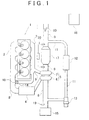
- FIG. 1 is a diagram showing an overall construction of an internal combustion engine and its intake-exhaust system equipped with an exhaust purification system in accordance with the invention.
- Combustion chambers of an internal combustion engine 1 in FIG. 1 are connected to an intake passageway 8 via an intake manifold 2.
- the intake passageway 8 is provided with an intercooler 4, and the intake passageway 8 upstream of the intercooler 4 is provided with a compressor 6 of a turbocharger 5.
- An air flow meter 19 and an air cleaner 15 are provided upstream of the compressor 6.
- the combustion chambers of the internal combustion engine 1 are also connected to an exhaust passageway 9 via an exhaust manifold 3.
- the turbine 7 of the turbocharger 5 is provided in the exhaust passageway 9.
- An exhaust purification device 17 is provided downstream of the turbine 7.
- the exhaust purification device 17 may be, for example, a PM filter that traps PM in exhaust gas, a NOx catalyst that stores and reduces NOx in exhaust gas, an oxidation catalyst that oxidizes unburned fuel or the like in exhaust gas, etc. A suitable combination thereof is also possible. Downstream of the exhaust purification device 17, the exhaust passageway 9 is open to the atmosphere.
- the exhaust passageway 9 is provided with a differential pressure sensor 20 that detects the differential pressure between the exhaust pressure upstream of the exhaust purification device 17 and the exhaust pressure downstream of the exhaust purification device 17.
- the exhaust passageway 9 downstream of the exhaust purification device 17 is provided with an exhaust throttle valve 10 that changes the channel cross-sectional area of the exhaust passageway 9.
- the exhaust throttle valve 10 is electrically connected to an ECU 16 (described later) and the ECU 16 outputs a control signal to adjust the valve opening degree of the exhaust throttle valve 10.
- a site in the exhaust passageway 9 that is downstream of the exhaust purification device 17 and upstream of the exhaust throttle valve 10, and a site in the intake passageway 8 that is upstream of the compressor 6 are communicably connected by a low-pressure EGR passageway 11.
- the low-pressure EGR passageway 11 is provided with a low-pressure EGR cooler 12 that cools the exhaust flowing through the low-pressure EGR passageway 11, and a low-pressure EGR valve 13 that changes the channel cross-sectional area of the low-pressure EGR passageway 11.
- the low-pressure EGR valve 13 adjusts the amount of exhaust gas that flows through the low-pressure EGR passageway 11 (hereinafter, referred to as "low-pressure EGR gas amount").
- the exhaust manifold 3 and the intake manifold 2 are communicably connected by a high-pressure EGR passageway 14.
- the high-pressure EGR passageway 14 is provided with a high-pressure EGR valve 18 that changes the channel cross-sectional area of the high-pressure EGR passageway 14.
- the high-pressure EGR valve 18 adjusts the amount of exhaust gas that flows through the high-pressure EGR passageway 14 (hereinafter, referred to as "high-pressure EGR gas amount'').
- a portion of the exhaust gas is recirculated into the intake system of the internal combustion engine 1 through the low-pressure EGR passageway 11 and the high-pressure EGR passageway 14. Therefore, exhaust gas is re-circulated into the combustion chambers of the internal combustion engine 1 to reduce the amount of NOx generated in the internal combustion engine 1.
- the internal combustion engine 1 is provided with the ECU 16, which is an electronic control computer that controls the internal combustion engine 1.
- the ECU 16 performs known controls of the internal combustion engine 1, such as a fuel injection control and the like, in accordance with the operating condition of the internal combustion engine 1 or a driver's request, and also performs an open-close control of the exhaust throttle valve 10.
- FIG. 2 is a diagram showing which one of the EGRs, that is, the EGR using the low-pressure EGR passageway 11 (hereinafter, referred to as "LPL-EGR”) and/or the EGR using the high-pressure EGR passageway 14 (hereinafter, referred to as "HPL-EGR”), is performed depending on regions of the operational state of the internal combustion engine 1.
- LPL-EGR low-pressure EGR passageway 11
- HPL-EGR high-pressure EGR passageway 14
- the HPL-EGR is mainly performed when the operational state of the internal combustion engine 1 is under low load and has a low rotation speed.
- both the HPL-EGR and the LPL-EGR are performed.
- the LPL-EGR is mainly performed.
- the exhaust throttle valve 10 is controlled to a closure side in comparison with when the internal combustion engine 1 operates under a high load and has a high rotation speed, to raise the exhaust pressure in the exhaust passageway 9 and therefore increase the differential pressure. In this manner, the low-pressure EGR gas amount is secured.
- the exhaust purification device 17 if an excessive temperature increase exceeds the heat resistance temperature of the material that constitutes the catalyst, the filter or the like or causes an enlarged local temperature difference, local differences in heat expansion may occur and therefore cause breakage such as cracking, chipping, etc of the exhaust purification catalyst. In a worst case, there is a risk that such breakage will result in broken pieces falling off from the exhaust purification device 17. Therefore, if breakage occurs in the exhaust purification device 17 when the exhaust throttle valve 10 is controlled in the valve closing direction, the exhaust throttle valve 10 under the valve closing control may become clogged with broken pieces of the exhaust purification device 17 so that the exhaust passageway is essentially blocked. If the exhaust passageway 9 is blocked, there is a risk of the internal combustion engine 1 coming to a stop.
- the valve closing control of the exhaust throttle valve 10 it is determined whether or not the exhaust purification device 17 is broken. If it is determined that the exhaust purification device 17 is broken, then the exhaust throttle valve 10 is fully opened. Therefore, even if the exhaust purification device 17 is broken and it is possible that broken pieces of the exhaust purification device 17 may flow down the exhaust passageway 9, accumulation of the broken pieces thereof on and around the exhaust throttle valve 10, and thereby blocking the exhaust passageway 9, is minimized by fully opening the exhaust throttle valve 10.
- the open-close control of the exhaust throttle valve 10 executed by the ECU 16 will be described with reference to the flowchart of FIG. 3.
- the flowchart of FIG. 3 shows the routine for executing the open-close control of the exhaust throttle valve 10. This routine is executed at regular intervals.
- the ECU 16 detects the amount of exhaust flowing through the exhaust purification device 17 (hereinafter, referred to as "catalyst gas flow amount").
- the catalyst gas flow amount may be estimated, for example, based on the intake amount detected by the air flow meter 19, the valve opening degree of the low-pressure EGR valve 13, and the valve opening degree of the high-pressure EGR valve 18.
- the ECU 16 calculates the pressure loss guard value Pgrd based on the catalyst gas flow amount detected in step 301.
- the pressure loss guard value Pgrd is the lower limit value of the differential pressure between the upstream and downstream sides of the exhaust purification device 17 which is calculated from the catalyst gas flow amount through the use of the exhaust resistance in the normal-condition exhaust purification device 17 that has no deposit thereon.
- the pressure loss guard value Pgrd may be determined beforehand through experiments or the like, in the form of a function or a map that is in accordance with the catalyst gas flow amount.
- step 303 the ECU 16 detects the upstream-downstream differential pressure Pact of the exhaust purification device 17 (hereinafter, referred to as "catalyst upstream-downstream differential pressure").
- the catalyst upstream-downstream differential pressure Pact is detected by the differential pressure sensor 20.
- step 304 the ECU 16 determines whether there is a possibility that the exhaust purification device 17 is broken. Concretely, the ECU 16 determines whether the catalyst upstream-downstream differential pressure Pact detected in step 303 is lower than the pressure loss guard value Pgrd calculated in step 302. The determination process is explained as follows. If the exhaust purification device 17 is broken, the channel cross-sectional area of the exhaust purification device 17 increases since, for example, a portion of the catalyst or the filter in the exhaust purification device 17 falls off. As a result, the pressure loss in the exhaust purification device 17 is reduced.
- step 304 If a negative determination is made in step 304 (Pact ⁇ Pgrd), the ECU 16 determines that the exhaust purification device 17 is not broken, and ends the routine.
- step 304 determines that there is a possibility that the exhaust purification device 17 is broken, and proceeds to step 305.
- step 305 the ECU 16 determines whether the differential pressure sensor 20 has failed.
- the failure determination regarding the differential pressure sensor 20 is performed by executing a known failure determination routine.
- step 305 the ECU 16 determines that due to the failure of the differential pressure sensor 20, the catalyst upstream-downstream differential pressure Pact that was detected is lower than the pressure loss guard value Pgrd in step 304, and proceeds to step 310.
- step 310 the ECU 16 switches of the operational state of the vehicle to a differential pressure sensor fail mode. In the differential pressure sensor fail mode, the lighting of a warning lamp or the like is performed in order to notify the failure of the differential pressure sensor to a driver. After executing step 310, the ECU 16 ends the routine.
- step 305 the ECU 16 determines that the cause of the detection in step 304 that the catalyst upstream-downstream differential pressure Pact is lower than the pressure loss guard value Pgrd is not a failure of the differential pressure sensor 20, and proceeds to step 306.
- the ECU 16 determines whether the temperature of the exhaust purification device 17 is equal to or higher than a limit value.
- the limit value herein is a lower limit value of the temperature that involves a risk of breakage of the exhaust purification device 17, and empirically determined beforehand.
- the temperature of the exhaust purification device 17 may be directly detected by mounting a temperature sensor on the exhaust purification device 17, or may also be estimated from the engine rotation speed and the engine load.
- step 306 determines that the exhaust purification device 17 is not broken, and proceeds to step 311.
- step 311 the ECU 16 determines that there is possibility of abnormality in the output of a sensor other than the differential pressure sensor 20, for example, the output of the air flow meter 19 used for the detection or estimation of the catalyst gas flow amount, or the like, and turns on a warning lamp or the like in order to notify the determination result to the driver.
- step 306 the ECU 16 determines that breakage of the exhaust purification device 17 is the cause of the detection in step 304 that the catalyst upstream-downstream differential pressure Pact is lower than the pressure loss guard value Pgrd, and proceeds to step 307.
- step 307 the ECU 16 turns on the warning lamp or the like in order to inform the driver that the exhaust purification device 17 has broken and that the internal combustion engine 1 will be operated in a save-run mode from then on.
- step 308 the ECU 16 fully opens the exhaust throttle valve 10. Therefore, even if broken pieces of the exhaust purification device 17 flow down the exhaust passageway 9, the broken pieces will be restrained from accumulating on and around the exhaust throttle valve 10. Thus, it becomes possible to restrain the blockage of the exhaust passageway 9.
- step 309 the ECU 16 restricts the operational state of the internal combustion engine 1 to the save-run mode.
- the save-run mode is an operational mode of the internal combustion engine 1 that allows the driver a minimum necessary propulsion of the vehicle to cope with the failure of the exhaust purification device 17. In the save-run mode, for example, the amount of fuel injection and the engine rotation speed are restricted.
- the ECU 16 ends this routine.
- the ECU 16, which executes step 304, step 305 and step 306 in the foregoing routine of the open-close control of the exhaust throttle valve 10 is an example of the determination means in accordance with the invention.
- the ECU 16, which executes step 308, is an example of the control means in accordance with the invention.
- the foregoing embodiment is an example for illustrating the invention, and may be modified in various ways without departing from the spirit of the invention.
- the degree of opening of the exhaust throttle valve 10 is controlled to the fully open state if it is determined that the exhaust purification device 17 is broken
- the similar effects characteristic of the foregoing embodiment may also be obtained when the exhaust throttle valve 10 is controlled to a degree of opening that is greater than (i.e., to the open side of) the degree of opening set when it is not determined that the exhaust purification device 17 is broken.
- the degree of opening of the exhaust throttle valve may be controlled to the fully open state or to the open side of the degree of opening of the valve set when it is determined that the PM filter is not broken.
- the low-pressure EGR passageway 11 may be connected to a side wall surface immediately downstream of the exhaust purification device 17, and a mesh 20 is provided at an inlet of the low-pressure EGR passageway 11. Therefore, a broken piece of the exhaust purification device 17 may be restrained from flowing into the low-pressure EGR passageway 11.
- the exhaust passageway 9, connected to the outlet of the exhaust purification device 17, is connected at a site vertically downward from the exhaust purification device 17, a broken piece of the exhaust purification device 17 may also be restrained from flowing into the low-pressure EGR passageway 11.
- the adoption of this construction also restrains a broken piece of the exhaust purification device 17 from flowing into the low-pressure EGR passageway 11 if the exhaust purification device 17 breaks. Therefore, it is possible to restrain the clogging of the low-pressure EGR passageway 11 or the low-pressure EGR cooler 12.
- the exhaust purification device 17 includes an oxidation catalyst 19 on an upstream side and a DPF 20 on a downstream side
- the catalyst used is not limited as long as the low-pressure EGR passageway 11 is connected to the side wall immediately downstream of the catalyst provided downstream of the exhaust purification device 17.
Landscapes
- Engineering & Computer Science (AREA)
- Chemical & Material Sciences (AREA)
- Combustion & Propulsion (AREA)
- Mechanical Engineering (AREA)
- General Engineering & Computer Science (AREA)
- Chemical Kinetics & Catalysis (AREA)
- Ceramic Engineering (AREA)
- Health & Medical Sciences (AREA)
- Toxicology (AREA)
- Exhaust Gas After Treatment (AREA)
- Control Of Throttle Valves Provided In The Intake System Or In The Exhaust System (AREA)
- Processes For Solid Components From Exhaust (AREA)
Abstract
Description
- The invention relates to an exhaust purification system of an internal combustion engine.
- Exhaust gas re-circulation (hereinafter, referred to as "EGR") is a known technology for lowering oxides of nitrogen (hereinafter, referred to as "NOx") discharged from internal combustion engines. The technology reduces the generation of NOx in the combustion process by re-circulating a portion of exhaust gas into the combustion chambers.
- In recent years, a low-pressure EGR device has also been developed as a technology that performs the EGR over a wider operational range of the internal combustion engine. In this EGR device, a portion of the exhaust gas flowing in an exhaust passageway downstream of the turbine of a turbocharger is recirculated into an intake passageway upstream of the compressor of the turbocharger (see, e.g.,
Japanese Patent Application Publication No. JP-A-2002-021625 - Incidentally, in some internal combustion engines equipped with a low-pressure EGR device, an exhaust throttle valve is provided in the exhaust passageway in so as to secure a differential pressure between the upstream and downstream sides of a low-pressure EGR passageway and therefore cause the performance of a sufficient amount of EGR. There are also constructions in which the exhaust passageway is provided with a PM filter, or an exhaust purification catalyst such as a NOx catalyst or the like.
- With regard to the exhaust purification catalyst, if an excessive temperature increase exceeds the heat resistance temperature of the material that constitutes the exhaust purification catalyst or causes an enlarged local temperature difference, local differences in heat expansion may occur and therefore cause breakage such as cracking, chipping, etc of the exhaust purification catalyst. In a worst case, there is a risk that such breakage will result in a broken piece falling off from the exhaust purification catalyst.
- In an internal combustion engine having a construction in which an exhaust purification catalyst is provided upstream of an exhaust throttle valve, if the exhaust purification catalyst breaks and pieces of the broken exhaust purification catalyst flow down the exhaust passageway while the exhaust throttle valve is controlled in a valve closing direction, the broken pieces may clog the exhaust throttle valve that has been controlled toward the closed state and therefore blocking the exhaust passageway. If the exhaust passageway is blocked, the internal combustion engine may stop operating.
- The invention provides a technology for an internal combustion engine equipped with an exhaust purification catalyst provided in an exhaust passageway upstream of an exhaust throttle valve that reduces the likelihood that the exhaust passageway will be blocked at the exhaust throttle valve even when the exhaust purification catalyst has broken.
- An exhaust purification system for an internal combustion engine in accordance with one aspect of the invention is characterized by including: an exhaust purification means for being provided in an exhaust passageway of the internal combustion engine and for purifying exhaust gas; an exhaust throttle valve provided in the exhaust passageway downstream of the exhaust purification means; determination means for determining whether the exhaust purification means is broken; and control means for controlling the exhaust throttle valve, such that the control means increases the opening degree, or fully opens, the exhaust throttle valve if it is determined that the exhaust purification means is broken.
- According to this construction, if the determination means determines that the exhaust purification means is broken, the exhaust throttle valve is controlled to the fully open state or to the open side of the degree of opening thereof set in the case where it is determined that the exhaust purification means is not broken. Therefore, even if the exhaust purification means breaks and broken pieces thereof flow down the exhaust passageway, the broken pieces pass through the exhaust throttle valve, substantially without being trapped or stuck on the exhaust throttle valve. Hence, it is possible to keep broken pieces of the exhaust purification means from accumulating on or around the exhaust throttle valve and blocking the exhaust passageway. In turn, it becomes possible to restrain the occurrence of troubles caused by the blockage of the exhaust passageway, such as a stop of the internal combustion engine or the like.
- Examples of the exhaust purification means include a PM filter that traps and oxidizes particulate matter (hereinafter, simply referred to as "PM") in exhaust gas, a NOx catalyst that stores and reduces NOx in exhaust gas, an oxidation catalyst that oxidizes unburned fuel or the like in the exhaust gas, and suitable combinations thereof.
- Examples of the foregoing exhaust purification system of an internal combustion engine having the exhaust purification means upstream of the exhaust throttle valve include an exhaust purification system that has an EGR means that recirculates a portion of the exhaust gas flowing in the exhaust passageway to the intake passageway via an EGR passageway that connects in communication the exhaust passageway downstream of the exhaust purification means and upstream of the exhaust throttle valve and the intake passageway.
- The amount of exhaust gas recirculated into the intake passageway by the EGR means (hereinafter, simply referred to as "EGR gas amount") is dependent on the differential pressure between the exhaust pressure in the exhaust passageway and the intake pressure in the intake passageway. Therefore, when exhaust gas is recirculated by the EGR means, the exhaust throttle valve is controlled to the closure side of the valve position set when exhaust gas is not recirculated by the EGR means. Since the exhaust throttle valve is controlled to the closure side, the differential pressure increases so that a sufficient EGR gas amount can be secured. Generally, the exhaust purification means is provided in the exhaust passageway upstream of an EGR gas extraction opening, so that the exhaust purified by the exhaust purification means will be recirculated to the intake passageway.
- Hence, in the exhaust purification system constructed as described above, if the exhaust purification means breaks while the exhaust throttle valve is controlled to the closure side, there is a risk that broken pieces of the exhaust purification means may accumulate on or around the exhaust throttle valve and thereby block the exhaust passageway.
- However, in this aspect of the invention, if it is determined that the exhaust purification means is broken, the open-close control of the exhaust throttle valve by the control means is performed preferentially over the control of the degree of opening of the exhaust throttle valve by the EGR means in association with the recirculation of exhaust gas. Specifically, even when the exhaust throttle valve is controlled to the closure side in association with the implementation of the recirculation of exhaust gas by the EGR means, the exhaust throttle valve is controlled to the fully open state or to the open side if the exhaust purification means breaks. Therefore, even if broken pieces of the exhaust purification means flow down the exhaust passageway, the broken pieces substantially do not accumulate on or around the exhaust throttle valve. Hence, it is possible to restrain such broken pieces from blocking the exhaust passageway.
- In an exhaust purification system that has an EGR means that recirculates exhaust gas via an EGR passageway that communicably connects the exhaust passageway downstream of the turbine of the turbocharger and the intake passageway upstream of the compressor of the turbocharger (hereinafter, referred to as "low-pressure EGR device"), the differential pressure between the exhaust pressure in the exhaust passageway and the intake pressure in the intake passageway is small and a sufficient EGR gas amount cannot be easily obtained during an intermediate-load operation state of internal combustion engine. Therefore, during such a state, the exhaust throttle valve is controlled to the closure side of the valve position set during a high-load operation state of the internal combustion engine.
- Therefore, if the exhaust purification means breaks while the recirculation of exhaust gas by the low-pressure EGR device (hereinafter, referred to as "low-pressure EGR") is being performed, the exhaust passageway may become blocked at the exhaust throttle valve. However, in the foregoing construction, even when the low-pressure EGR is being performed, the exhaust throttle valve is controlled to the fully open state or to the open side if the exhaust purification means is broken. This restrains broken pieces of the exhaust purification means from blocking the exhaust passageway.
- Examples of the exhaust purification system of an internal combustion engine having an exhaust purification means upstream of the exhaust throttle valve include an exhaust purification system which has a PM filter as an exhaust purification means, and which raises the temperature of the PM filter by controlling the exhaust throttle valve to the closure side during the implementation of the PM restoration process of removing PM deposit from the PM filter.
- In such an exhaust purification system, too, if the PM filter breaks during the implementation of the process of raising the temperature of the PM filter, there is a possibility of broken pieces of the PM filter accumulating on and around the exhaust throttle valve and blocking the exhaust passageway.
- Hence, in the exhaust purification system constructed as described above, too, when it is determined that the PM filter is broken, the exhaust throttle valve may be controlled to the fully open state or to the open side regardless of whether or not the PM filter temperature raising operation is being executed. Therefore, the blockage of the exhaust passageway by broken pieces of the PM filter may be restrained.
- According to this aspect of the invention, in the internal combustion engine having the exhaust purification means in the exhaust passageway upstream of the exhaust throttle valve, even if the exhaust purification means breaks, broken pieces of the exhaust purification means may be restrained from accumulating on and around the exhaust throttle valve and blocking the exhaust passageway.
- The foregoing and further objects, features and advantages of the invention will become apparent from the following description of preferred embodiments with reference to the accompanying drawings, wherein like numerals are used to represent like elements and wherein:
- FIG. 1 is a diagram showing an overall construction of an internal combustion engine and its intake-exhaust system in accordance with an embodiment of the invention is applied;
- FIG. 2 is a diagram showing the operational states of the internal combustion engine in which LPL-EGR or HPL-EGR is performed in the embodiment;
- FIG. 3 is a flowchart showing an open-close control routine for an exhaust throttle valve in the embodiment; and
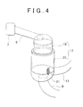
- FIG. 4 is a diagram showing an
exhaust purification device 17 in the embodiment, and a connecting portion between theexhaust purification device 17 and a low-pressure EGR passageway 11. - An example embodiment of the invention will be described in detail hereinafter with reference to the drawings.
- FIG. 1 is a diagram showing an overall construction of an internal combustion engine and its intake-exhaust system equipped with an exhaust purification system in accordance with the invention.
- Combustion chambers of an
internal combustion engine 1 in FIG. 1 are connected to anintake passageway 8 via anintake manifold 2. Theintake passageway 8 is provided with anintercooler 4, and theintake passageway 8 upstream of theintercooler 4 is provided with a compressor 6 of a turbocharger 5. Anair flow meter 19 and anair cleaner 15 are provided upstream of the compressor 6. - The combustion chambers of the
internal combustion engine 1 are also connected to anexhaust passageway 9 via an exhaust manifold 3. Theturbine 7 of the turbocharger 5 is provided in theexhaust passageway 9. Anexhaust purification device 17 is provided downstream of theturbine 7. Theexhaust purification device 17 may be, for example, a PM filter that traps PM in exhaust gas, a NOx catalyst that stores and reduces NOx in exhaust gas, an oxidation catalyst that oxidizes unburned fuel or the like in exhaust gas, etc. A suitable combination thereof is also possible. Downstream of theexhaust purification device 17, theexhaust passageway 9 is open to the atmosphere. - The
exhaust passageway 9 is provided with adifferential pressure sensor 20 that detects the differential pressure between the exhaust pressure upstream of theexhaust purification device 17 and the exhaust pressure downstream of theexhaust purification device 17. In addition, theexhaust passageway 9 downstream of theexhaust purification device 17 is provided with anexhaust throttle valve 10 that changes the channel cross-sectional area of theexhaust passageway 9. Theexhaust throttle valve 10 is electrically connected to an ECU 16 (described later) and theECU 16 outputs a control signal to adjust the valve opening degree of theexhaust throttle valve 10. - A site in the
exhaust passageway 9 that is downstream of theexhaust purification device 17 and upstream of theexhaust throttle valve 10, and a site in theintake passageway 8 that is upstream of the compressor 6 are communicably connected by a low-pressure EGR passageway 11. The low-pressure EGR passageway 11 is provided with a low-pressure EGR cooler 12 that cools the exhaust flowing through the low-pressure EGR passageway 11, and a low-pressure EGR valve 13 that changes the channel cross-sectional area of the low-pressure EGR passageway 11. The low-pressure EGR valve 13 adjusts the amount of exhaust gas that flows through the low-pressure EGR passageway 11 (hereinafter, referred to as "low-pressure EGR gas amount"). In addition, the exhaust manifold 3 and theintake manifold 2 are communicably connected by a high-pressure EGR passageway 14. The high-pressure EGR passageway 14 is provided with a high-pressure EGR valve 18 that changes the channel cross-sectional area of the high-pressure EGR passageway 14. The high-pressure EGR valve 18 adjusts the amount of exhaust gas that flows through the high-pressure EGR passageway 14 (hereinafter, referred to as "high-pressure EGR gas amount''). - A portion of the exhaust gas is recirculated into the intake system of the
internal combustion engine 1 through the low-pressure EGR passageway 11 and the high-pressure EGR passageway 14. Therefore, exhaust gas is re-circulated into the combustion chambers of theinternal combustion engine 1 to reduce the amount of NOx generated in theinternal combustion engine 1. - The
internal combustion engine 1 is provided with theECU 16, which is an electronic control computer that controls theinternal combustion engine 1. TheECU 16 performs known controls of theinternal combustion engine 1, such as a fuel injection control and the like, in accordance with the operating condition of theinternal combustion engine 1 or a driver's request, and also performs an open-close control of theexhaust throttle valve 10. - In an exhaust purification system of the
internal combustion engine 1 having the above-described construction, the EGR that uses the low-pressure EGR passageway 11 and/or the high-pressure EGR passageway 14 is performed in accordance with the operational state of theinternal combustion engine 1. FIG. 2 is a diagram showing which one of the EGRs, that is, the EGR using the low-pressure EGR passageway 11 (hereinafter, referred to as "LPL-EGR") and/or the EGR using the high-pressure EGR passageway 14 (hereinafter, referred to as "HPL-EGR"), is performed depending on regions of the operational state of theinternal combustion engine 1. In FIG. 2, the horizontal axis represents the engine rotation speed of theinternal combustion engine 1, and the vertical axis represents the amount of fuel injection of theinternal combustion engine 1. The amount of fuel injection is a parameter that represents the load of theinternal combustion engine 1. - As shown in FIG. 2, the HPL-EGR is mainly performed when the operational state of the
internal combustion engine 1 is under low load and has a low rotation speed. When the operational state of theinternal combustion engine 1 is under an intermediate load and has an intermediate rotation speed, both the HPL-EGR and the LPL-EGR are performed. When theinternal combustion engine 1 is under a high load and has a high rotation speed, the LPL-EGR is mainly performed. - When the
internal combustion engine 1 is under a high load and has a high rotation speed, the exhaust pressure in theexhaust passageway 9 is high, so that the differential pressure between the exhaust pressure in theexhaust passageway 9 and the intake pressure in theintake passageway 8 is also high. Therefore, sufficient low-pressure EGR gas amount can be secured. However, when theinternal combustion engine 1 is under an intermediate load and has an intermediate rotation speed, the exhaust pressure in theexhaust passageway 9 is not high, thus,the differential pressure does not become great. Therefore, in some of such cases, sufficient low-pressure EGR gas amount is not obtained. Hence, in such a case, theexhaust throttle valve 10 is controlled to a closure side in comparison with when theinternal combustion engine 1 operates under a high load and has a high rotation speed, to raise the exhaust pressure in theexhaust passageway 9 and therefore increase the differential pressure. In this manner, the low-pressure EGR gas amount is secured. - With regard to the
exhaust purification device 17, if an excessive temperature increase exceeds the heat resistance temperature of the material that constitutes the catalyst, the filter or the like or causes an enlarged local temperature difference, local differences in heat expansion may occur and therefore cause breakage such as cracking, chipping, etc of the exhaust purification catalyst. In a worst case, there is a risk that such breakage will result in broken pieces falling off from theexhaust purification device 17. Therefore, if breakage occurs in theexhaust purification device 17 when theexhaust throttle valve 10 is controlled in the valve closing direction, theexhaust throttle valve 10 under the valve closing control may become clogged with broken pieces of theexhaust purification device 17 so that the exhaust passageway is essentially blocked. If theexhaust passageway 9 is blocked, there is a risk of theinternal combustion engine 1 coming to a stop. - Therefore in this embodiment, in the valve closing control of the
exhaust throttle valve 10, it is determined whether or not theexhaust purification device 17 is broken. If it is determined that theexhaust purification device 17 is broken, then theexhaust throttle valve 10 is fully opened. Therefore, even if theexhaust purification device 17 is broken and it is possible that broken pieces of theexhaust purification device 17 may flow down theexhaust passageway 9, accumulation of the broken pieces thereof on and around theexhaust throttle valve 10, and thereby blocking theexhaust passageway 9, is minimized by fully opening theexhaust throttle valve 10. - The open-close control of the
exhaust throttle valve 10 executed by theECU 16 will be described with reference to the flowchart of FIG. 3. The flowchart of FIG. 3 shows the routine for executing the open-close control of theexhaust throttle valve 10. This routine is executed at regular intervals. - First, in
step 301, theECU 16 detects the amount of exhaust flowing through the exhaust purification device 17 (hereinafter, referred to as "catalyst gas flow amount"). The catalyst gas flow amount may be estimated, for example, based on the intake amount detected by theair flow meter 19, the valve opening degree of the low-pressure EGR valve 13, and the valve opening degree of the high-pressure EGR valve 18. - Subsequently in
step 302, theECU 16 calculates the pressure loss guard value Pgrd based on the catalyst gas flow amount detected instep 301. The pressure loss guard value Pgrd is the lower limit value of the differential pressure between the upstream and downstream sides of theexhaust purification device 17 which is calculated from the catalyst gas flow amount through the use of the exhaust resistance in the normal-conditionexhaust purification device 17 that has no deposit thereon. The pressure loss guard value Pgrd may be determined beforehand through experiments or the like, in the form of a function or a map that is in accordance with the catalyst gas flow amount. - In
step 303, theECU 16 detects the upstream-downstream differential pressure Pact of the exhaust purification device 17 (hereinafter, referred to as "catalyst upstream-downstream differential pressure"). The catalyst upstream-downstream differential pressure Pact is detected by thedifferential pressure sensor 20. - In
step 304, theECU 16 determines whether there is a possibility that theexhaust purification device 17 is broken. Concretely, theECU 16 determines whether the catalyst upstream-downstream differential pressure Pact detected instep 303 is lower than the pressure loss guard value Pgrd calculated instep 302. The determination process is explained as follows. If theexhaust purification device 17 is broken, the channel cross-sectional area of theexhaust purification device 17 increases since, for example, a portion of the catalyst or the filter in theexhaust purification device 17 falls off. As a result, the pressure loss in theexhaust purification device 17 is reduced. - If a negative determination is made in step 304 (Pact≥Pgrd), the
ECU 16 determines that theexhaust purification device 17 is not broken, and ends the routine. - On the other hand, if an affirmative determination is made in step 304 (Pact<Pgrd), the
ECU 16 determines that there is a possibility that theexhaust purification device 17 is broken, and proceeds to step 305. - In
step 305, theECU 16 determines whether thedifferential pressure sensor 20 has failed. The failure determination regarding thedifferential pressure sensor 20 is performed by executing a known failure determination routine. - If an affirmative determination is made in
step 305, theECU 16 determines that due to the failure of thedifferential pressure sensor 20, the catalyst upstream-downstream differential pressure Pact that was detected is lower than the pressure loss guard value Pgrd instep 304, and proceeds to step 310. Instep 310, theECU 16 switches of the operational state of the vehicle to a differential pressure sensor fail mode. In the differential pressure sensor fail mode, the lighting of a warning lamp or the like is performed in order to notify the failure of the differential pressure sensor to a driver. After executingstep 310, theECU 16 ends the routine. - On the other hand, if a negative determination is made in
step 305, theECU 16 determines that the cause of the detection instep 304 that the catalyst upstream-downstream differential pressure Pact is lower than the pressure loss guard value Pgrd is not a failure of thedifferential pressure sensor 20, and proceeds to step 306. - In
step 306, theECU 16 determines whether the temperature of theexhaust purification device 17 is equal to or higher than a limit value. The limit value herein is a lower limit value of the temperature that involves a risk of breakage of theexhaust purification device 17, and empirically determined beforehand. The temperature of theexhaust purification device 17 may be directly detected by mounting a temperature sensor on theexhaust purification device 17, or may also be estimated from the engine rotation speed and the engine load. - If a negative determination is made in
step 306, theECU 16 determines that theexhaust purification device 17 is not broken, and proceeds to step 311. Instep 311, theECU 16 determines that there is possibility of abnormality in the output of a sensor other than thedifferential pressure sensor 20, for example, the output of theair flow meter 19 used for the detection or estimation of the catalyst gas flow amount, or the like, and turns on a warning lamp or the like in order to notify the determination result to the driver. - On the other hand, if an affirmative determination is made in
step 306, theECU 16 determines that breakage of theexhaust purification device 17 is the cause of the detection instep 304 that the catalyst upstream-downstream differential pressure Pact is lower than the pressure loss guard value Pgrd, and proceeds to step 307. - In
step 307, theECU 16 turns on the warning lamp or the like in order to inform the driver that theexhaust purification device 17 has broken and that theinternal combustion engine 1 will be operated in a save-run mode from then on. - Subsequently in
step 308, theECU 16 fully opens theexhaust throttle valve 10. Therefore, even if broken pieces of theexhaust purification device 17 flow down theexhaust passageway 9, the broken pieces will be restrained from accumulating on and around theexhaust throttle valve 10. Thus, it becomes possible to restrain the blockage of theexhaust passageway 9. - In
step 309, theECU 16 restricts the operational state of theinternal combustion engine 1 to the save-run mode. The save-run mode is an operational mode of theinternal combustion engine 1 that allows the driver a minimum necessary propulsion of the vehicle to cope with the failure of theexhaust purification device 17. In the save-run mode, for example, the amount of fuel injection and the engine rotation speed are restricted. After switching the operational state of theinternal combustion engine 1 to the save-run mode instep 309, theECU 16 ends this routine. - In this embodiment, the
ECU 16, which executesstep 304,step 305 and step 306 in the foregoing routine of the open-close control of theexhaust throttle valve 10, is an example of the determination means in accordance with the invention. In addition, theECU 16, which executesstep 308, is an example of the control means in accordance with the invention. - The foregoing embodiment is an example for illustrating the invention, and may be modified in various ways without departing from the spirit of the invention. For example, although in the foregoing routine, the degree of opening of the
exhaust throttle valve 10 is controlled to the fully open state if it is determined that theexhaust purification device 17 is broken, the similar effects characteristic of the foregoing embodiment may also be obtained when theexhaust throttle valve 10 is controlled to a degree of opening that is greater than (i.e., to the open side of) the degree of opening set when it is not determined that theexhaust purification device 17 is broken. - Furthermore, in an exhaust purification system that includes a PM filter as the
exhaust purification device 17 and that raises the temperature of the PM filter by controlling the exhaust throttle valve toward the closure side when implementing a PM restoration process of removing deposits of PM from the PM filter, if it is determined that the PM filter is broken, the degree of opening of the exhaust throttle valve may be controlled to the fully open state or to the open side of the degree of opening of the valve set when it is determined that the PM filter is not broken. - Thus, if the PM filter breaks during the execution of the process of raising the temperature of the PM filter, the blockage of the exhaust passageway by broken pieces of the PM filter can be restrained.
- Furthermore, a construction shown in FIG. 4 is also possible. In this construction, the low-
pressure EGR passageway 11 may be connected to a side wall surface immediately downstream of theexhaust purification device 17, and amesh 20 is provided at an inlet of the low-pressure EGR passageway 11. Therefore, a broken piece of theexhaust purification device 17 may be restrained from flowing into the low-pressure EGR passageway 11. In addition, if theexhaust passageway 9, connected to the outlet of theexhaust purification device 17, is connected at a site vertically downward from theexhaust purification device 17, a broken piece of theexhaust purification device 17 may also be restrained from flowing into the low-pressure EGR passageway 11. Therefore, the adoption of this construction also restrains a broken piece of theexhaust purification device 17 from flowing into the low-pressure EGR passageway 11 if theexhaust purification device 17 breaks. Therefore, it is possible to restrain the clogging of the low-pressure EGR passageway 11 or the low-pressure EGR cooler 12. - Although in FIG. 4, the
exhaust purification device 17 includes anoxidation catalyst 19 on an upstream side and aDPF 20 on a downstream side, the catalyst used is not limited as long as the low-pressure EGR passageway 11 is connected to the side wall immediately downstream of the catalyst provided downstream of theexhaust purification device 17.
Claims (6)
- An exhaust purification system of an internal combustion engine (1) characterized by comprising:an exhaust purification means (17) for being provided in an exhaust passageway (9) of the internal combustion engine (1) and for purifying exhaust gas;an exhaust throttle valve (10) provided in the exhaust passageway (9) downstream of the exhaust purification means (17);determination means (16) for determining whether the exhaust purification means (17) is broken; andcontrol means (16) for controlling the exhaust throttle valve (10), wherein the control means (16) increases an opening degree or fully opens the exhaust throttle valve (10) if it is determined that the exhaust purification means (17) is broken.
- The exhaust purification system of the internal combustion engine (1) according to claim 1, characterized by further comprising:an EGR means for having an EGR passageway (11) that communicably connects the exhaust passageway (9) downstream of the exhaust purification means (17) and upstream of the exhaust throttle valve (10) with an intake passageway (8), and for recirculating a portion of the exhaust from the exhaust passageway (9) to the intake passageway (8) via the EGR passageway (11); andEGR control means (16) for controlling the exhaust throttle valve (10) when the exhaust gas is recirculated by the EGR means so that the degree of opening of the exhaust throttle valve (10) is set smaller than the degree of opening set when the exhaust gas is not recirculated by the EGR means,wherein if it is determined by the determination means (16) that the exhaust purification means (17) is broken, the control of the degree of opening of the exhaust throttle valve (10) by the EGR control means (16) is given a priority over the control of the degree of opening of the exhaust throttle valve (10) by the control means (16).
- The exhaust purification system of the internal combustion engine (1) according to claim 2, characterized by further comprising:a turbocharger (5), having a compressor (6) provided in the intake passageway (8) and a turbine (7) provided in the exhaust passageway (9), wherein the EGR passageway (11) communicably connects the exhaust passageway (9) downstream of the turbine (7) and the intake passageway (8) upstream of the compressor (6).
- The exhaust purification system of the internal combustion engine (1) according to claim 2 or 3, characterized in that the determination means (16) determines that the exhaust purification means (17) is broken, if a differential pressure between the intake passageway (8) and the exhaust passageway (9) is below a predetermined value.
- The exhaust purification system of the internal combustion engine (1) according to claim 2 or 3, characterized in that the determination means (16) determines that the exhaust purification means (17) is broken, if the differential pressure between the intake passageway (8) and the exhaust passageway (9) is below the predetermined value and a temperature of the exhaust purification means (17) is equal to or above a predetermined temperature.
- The exhaust purification system of the internal combustion engine (1) according to any one of claims 2 to 5, characterized by further comprising:engine control means (16) for controlling the internal combustion engine (1),wherein if it is determined that the exhaust purification means (17) is broken, the engine control means (16) reduces an output of the internal combustion engine (1).
Applications Claiming Priority (1)
| Application Number | Priority Date | Filing Date | Title |
|---|---|---|---|
| JP2006108552A JP4179332B2 (en) | 2006-04-11 | 2006-04-11 | Exhaust gas purification system for internal combustion engine |
Publications (3)
| Publication Number | Publication Date |
|---|---|
| EP1845244A2 true EP1845244A2 (en) | 2007-10-17 |
| EP1845244A3 EP1845244A3 (en) | 2009-04-29 |
| EP1845244B1 EP1845244B1 (en) | 2010-08-04 |
Family
ID=38421516
Family Applications (1)
| Application Number | Title | Priority Date | Filing Date |
|---|---|---|---|
| EP07105893A Not-in-force EP1845244B1 (en) | 2006-04-11 | 2007-04-10 | Exhaust gas purification system of internal combustion engine |
Country Status (3)
| Country | Link |
|---|---|
| EP (1) | EP1845244B1 (en) |
| JP (1) | JP4179332B2 (en) |
| DE (1) | DE602007008161D1 (en) |
Cited By (4)
| Publication number | Priority date | Publication date | Assignee | Title |
|---|---|---|---|---|
| DE102008015600A1 (en) * | 2008-03-26 | 2009-10-01 | Volkswagen Ag | Method for operating internal combustion engine, particularly diesel engine, involves guiding exhaust gas over particle filter, particularly diesel particle filter, in exhaust gas system |
| FR2949507A1 (en) * | 2009-08-25 | 2011-03-04 | Peugeot Citroen Automobiles Sa | Particle filter failure detecting method for protecting supercharged diesel engine, involves comparing difference between estimated and measured temperatures with threshold, and deciding failure of filter based on comparison results |
| US20180258822A1 (en) * | 2017-03-10 | 2018-09-13 | Mazda Motor Corporation | Exhaust device of engine |
| CN110159437A (en) * | 2018-02-14 | 2019-08-23 | 福特全球技术公司 | System and method for engine poppet valve diagnosis |
Citations (1)
| Publication number | Priority date | Publication date | Assignee | Title |
|---|---|---|---|---|
| JP2002021625A (en) | 2000-07-10 | 2002-01-23 | Hino Motors Ltd | EGR device |
Family Cites Families (2)
| Publication number | Priority date | Publication date | Assignee | Title |
|---|---|---|---|---|
| JP3473583B2 (en) * | 2000-07-24 | 2003-12-08 | トヨタ自動車株式会社 | Exhaust gas purification device for internal combustion engine |
| JP4407787B2 (en) * | 2001-09-21 | 2010-02-03 | 三菱自動車工業株式会社 | Exhaust gas purification device for internal combustion engine |
-
2006
- 2006-04-11 JP JP2006108552A patent/JP4179332B2/en not_active Expired - Fee Related
-
2007
- 2007-04-10 DE DE602007008161T patent/DE602007008161D1/en active Active
- 2007-04-10 EP EP07105893A patent/EP1845244B1/en not_active Not-in-force
Patent Citations (1)
| Publication number | Priority date | Publication date | Assignee | Title |
|---|---|---|---|---|
| JP2002021625A (en) | 2000-07-10 | 2002-01-23 | Hino Motors Ltd | EGR device |
Cited By (8)
| Publication number | Priority date | Publication date | Assignee | Title |
|---|---|---|---|---|
| DE102008015600A1 (en) * | 2008-03-26 | 2009-10-01 | Volkswagen Ag | Method for operating internal combustion engine, particularly diesel engine, involves guiding exhaust gas over particle filter, particularly diesel particle filter, in exhaust gas system |
| FR2949507A1 (en) * | 2009-08-25 | 2011-03-04 | Peugeot Citroen Automobiles Sa | Particle filter failure detecting method for protecting supercharged diesel engine, involves comparing difference between estimated and measured temperatures with threshold, and deciding failure of filter based on comparison results |
| US20180258822A1 (en) * | 2017-03-10 | 2018-09-13 | Mazda Motor Corporation | Exhaust device of engine |
| CN108571354A (en) * | 2017-03-10 | 2018-09-25 | 马自达汽车株式会社 | The exhaust apparatus of engine |
| US10550750B2 (en) | 2017-03-10 | 2020-02-04 | Mazda Motor Corporation | Exhaust device of engine |
| CN108571354B (en) * | 2017-03-10 | 2020-12-25 | 马自达汽车株式会社 | Exhaust device of engine |
| DE102018001426B4 (en) * | 2017-03-10 | 2026-01-22 | Mazda Motor Corporation | Exhaust device for an engine and method for detecting a pressure drop in a particulate filter |
| CN110159437A (en) * | 2018-02-14 | 2019-08-23 | 福特全球技术公司 | System and method for engine poppet valve diagnosis |
Also Published As
| Publication number | Publication date |
|---|---|
| JP4179332B2 (en) | 2008-11-12 |
| EP1845244A3 (en) | 2009-04-29 |
| JP2007278248A (en) | 2007-10-25 |
| EP1845244B1 (en) | 2010-08-04 |
| DE602007008161D1 (en) | 2010-09-16 |
Similar Documents
| Publication | Publication Date | Title |
|---|---|---|
| EP1420159B1 (en) | EGR system for internal combustion engine provided with a turbo-charger | |
| JP4737335B2 (en) | EGR system for internal combustion engine | |
| EP1759099B1 (en) | Exhaust gas control apparatus for internal combustion engine | |
| JP2008150955A (en) | Exhaust gas recirculation device | |
| JP2010265854A (en) | Internal combustion engine with turbocharger and control method thereof | |
| JP2008157192A (en) | Exhaust gas purification device for internal combustion engine | |
| US20080249698A1 (en) | Internal Combustion Engine Fail-Safe Control Device and Method | |
| EP1845244B1 (en) | Exhaust gas purification system of internal combustion engine | |
| EP2404041B1 (en) | Diesel engine system and method for handling diesel engine exhaust | |
| JP5212923B2 (en) | Control device for internal combustion engine | |
| JP4670592B2 (en) | Exhaust gas recirculation system for internal combustion engines | |
| JP4556800B2 (en) | Engine back pressure control device | |
| JP4969225B2 (en) | Engine exhaust system with DPF device | |
| JP4742970B2 (en) | Exhaust gas recirculation device for internal combustion engine | |
| JP2008208721A (en) | Exhaust gas recirculation device for internal combustion engine | |
| JP4735505B2 (en) | Surge prevention control device and surge prevention control method for turbocharged engine | |
| JP2008050946A (en) | Exhaust gas recirculation system for internal combustion engine | |
| KR102163793B1 (en) | Vehicle Emergency Control System and method in case of DPF failure | |
| JP2008309052A (en) | Control device for internal combustion engine | |
| JP4044836B2 (en) | Exhaust gas purification device for internal combustion engine | |
| JP6116047B2 (en) | Turbocharged engine | |
| JP2007291975A (en) | Exhaust gas recirculation device for internal combustion engine | |
| JP2010209687A (en) | Egr device for internal combustion engine | |
| JP2009150356A (en) | Catalyst temperature fall suppression device | |
| JP2015102013A (en) | Control device of internal combustion engine |
Legal Events
| Date | Code | Title | Description |
|---|---|---|---|
| PUAI | Public reference made under article 153(3) epc to a published international application that has entered the european phase |
Free format text: ORIGINAL CODE: 0009012 |
|
| 17P | Request for examination filed |
Effective date: 20070410 |
|
| AK | Designated contracting states |
Kind code of ref document: A2 Designated state(s): AT BE BG CH CY CZ DE DK EE ES FI FR GB GR HU IE IS IT LI LT LU LV MC MT NL PL PT RO SE SI SK TR |
|
| AX | Request for extension of the european patent |
Extension state: AL BA HR MK YU |
|
| PUAL | Search report despatched |
Free format text: ORIGINAL CODE: 0009013 |
|
| AK | Designated contracting states |
Kind code of ref document: A3 Designated state(s): AT BE BG CH CY CZ DE DK EE ES FI FR GB GR HU IE IS IT LI LT LU LV MC MT NL PL PT RO SE SI SK TR |
|
| AX | Request for extension of the european patent |
Extension state: AL BA HR MK RS |
|
| RIC1 | Information provided on ipc code assigned before grant |
Ipc: F02D 41/22 20060101ALI20090326BHEP Ipc: F02D 41/00 20060101ALI20090326BHEP Ipc: F02B 37/00 20060101ALI20090326BHEP Ipc: F02M 25/07 20060101ALN20090326BHEP Ipc: F01N 11/00 20060101ALI20090326BHEP Ipc: F02B 29/04 20060101ALN20090326BHEP Ipc: F02D 9/04 20060101AFI20070830BHEP |
|
| 17Q | First examination report despatched |
Effective date: 20090814 |
|
| AKX | Designation fees paid |
Designated state(s): DE FR GB IT |
|
| GRAP | Despatch of communication of intention to grant a patent |
Free format text: ORIGINAL CODE: EPIDOSNIGR1 |
|
| GRAS | Grant fee paid |
Free format text: ORIGINAL CODE: EPIDOSNIGR3 |
|
| GRAA | (expected) grant |
Free format text: ORIGINAL CODE: 0009210 |
|
| AK | Designated contracting states |
Kind code of ref document: B1 Designated state(s): DE FR GB IT |
|
| REG | Reference to a national code |
Ref country code: GB Ref legal event code: FG4D |
|
| REF | Corresponds to: |
Ref document number: 602007008161 Country of ref document: DE Date of ref document: 20100916 Kind code of ref document: P |
|
| PLBE | No opposition filed within time limit |
Free format text: ORIGINAL CODE: 0009261 |
|
| STAA | Information on the status of an ep patent application or granted ep patent |
Free format text: STATUS: NO OPPOSITION FILED WITHIN TIME LIMIT |
|
| 26N | No opposition filed |
Effective date: 20110506 |
|
| REG | Reference to a national code |
Ref country code: DE Ref legal event code: R097 Ref document number: 602007008161 Country of ref document: DE Effective date: 20110506 |
|
| REG | Reference to a national code |
Ref country code: GB Ref legal event code: 746 Effective date: 20130128 |
|
| REG | Reference to a national code |
Ref country code: DE Ref legal event code: R084 Ref document number: 602007008161 Country of ref document: DE Effective date: 20130125 |
|
| REG | Reference to a national code |
Ref country code: FR Ref legal event code: PLFP Year of fee payment: 9 |
|
| PGFP | Annual fee paid to national office [announced via postgrant information from national office to epo] |
Ref country code: DE Payment date: 20150408 Year of fee payment: 9 Ref country code: GB Payment date: 20150408 Year of fee payment: 9 |
|
| PGFP | Annual fee paid to national office [announced via postgrant information from national office to epo] |
Ref country code: FR Payment date: 20150408 Year of fee payment: 9 |
|
| PGFP | Annual fee paid to national office [announced via postgrant information from national office to epo] |
Ref country code: IT Payment date: 20160418 Year of fee payment: 10 |
|
| REG | Reference to a national code |
Ref country code: DE Ref legal event code: R119 Ref document number: 602007008161 Country of ref document: DE |
|
| GBPC | Gb: european patent ceased through non-payment of renewal fee |
Effective date: 20160410 |
|
| REG | Reference to a national code |
Ref country code: FR Ref legal event code: ST Effective date: 20161230 |
|
| PG25 | Lapsed in a contracting state [announced via postgrant information from national office to epo] |
Ref country code: GB Free format text: LAPSE BECAUSE OF NON-PAYMENT OF DUE FEES Effective date: 20160410 Ref country code: FR Free format text: LAPSE BECAUSE OF NON-PAYMENT OF DUE FEES Effective date: 20160502 Ref country code: DE Free format text: LAPSE BECAUSE OF NON-PAYMENT OF DUE FEES Effective date: 20161101 |
|
| PG25 | Lapsed in a contracting state [announced via postgrant information from national office to epo] |
Ref country code: IT Free format text: LAPSE BECAUSE OF NON-PAYMENT OF DUE FEES Effective date: 20170410 |