EP1845006A2 - Steering wheel retracting device for vehicle - Google Patents
Steering wheel retracting device for vehicle Download PDFInfo
- Publication number
- EP1845006A2 EP1845006A2 EP07251435A EP07251435A EP1845006A2 EP 1845006 A2 EP1845006 A2 EP 1845006A2 EP 07251435 A EP07251435 A EP 07251435A EP 07251435 A EP07251435 A EP 07251435A EP 1845006 A2 EP1845006 A2 EP 1845006A2
- Authority
- EP
- European Patent Office
- Prior art keywords
- steering wheel
- vehicle
- cylinder housing
- piston rod
- shaft
- Prior art date
- Legal status (The legal status is an assumption and is not a legal conclusion. Google has not performed a legal analysis and makes no representation as to the accuracy of the status listed.)
- Withdrawn
Links
- 230000008878 coupling Effects 0.000 claims abstract description 16
- 238000010168 coupling process Methods 0.000 claims abstract description 16
- 238000005859 coupling reaction Methods 0.000 claims abstract description 16
- 239000012530 fluid Substances 0.000 claims description 5
- 230000035939 shock Effects 0.000 description 4
- 239000002360 explosive Substances 0.000 description 2
- 239000007789 gas Substances 0.000 description 2
- 230000002093 peripheral effect Effects 0.000 description 2
- 206010061245 Internal injury Diseases 0.000 description 1
- 208000027418 Wounds and injury Diseases 0.000 description 1
- 230000000712 assembly Effects 0.000 description 1
- 238000000429 assembly Methods 0.000 description 1
- 230000006378 damage Effects 0.000 description 1
- 239000010720 hydraulic oil Substances 0.000 description 1
- 208000014674 injury Diseases 0.000 description 1
Images


Classifications
-
- B—PERFORMING OPERATIONS; TRANSPORTING
- B62—LAND VEHICLES FOR TRAVELLING OTHERWISE THAN ON RAILS
- B62D—MOTOR VEHICLES; TRAILERS
- B62D1/00—Steering controls, i.e. means for initiating a change of direction of the vehicle
- B62D1/02—Steering controls, i.e. means for initiating a change of direction of the vehicle vehicle-mounted
- B62D1/16—Steering columns
- B62D1/18—Steering columns yieldable or adjustable, e.g. tiltable
- B62D1/19—Steering columns yieldable or adjustable, e.g. tiltable incorporating energy-absorbing arrangements, e.g. by being yieldable or collapsible
-
- B—PERFORMING OPERATIONS; TRANSPORTING
- B62—LAND VEHICLES FOR TRAVELLING OTHERWISE THAN ON RAILS
- B62D—MOTOR VEHICLES; TRAILERS
- B62D1/00—Steering controls, i.e. means for initiating a change of direction of the vehicle
- B62D1/02—Steering controls, i.e. means for initiating a change of direction of the vehicle vehicle-mounted
- B62D1/16—Steering columns
- B62D1/18—Steering columns yieldable or adjustable, e.g. tiltable
- B62D1/19—Steering columns yieldable or adjustable, e.g. tiltable incorporating energy-absorbing arrangements, e.g. by being yieldable or collapsible
- B62D1/197—Steering columns yieldable or adjustable, e.g. tiltable incorporating energy-absorbing arrangements, e.g. by being yieldable or collapsible incorporating devices for preventing ingress of the steering column into the passengers space in case of accident
-
- B—PERFORMING OPERATIONS; TRANSPORTING
- B60—VEHICLES IN GENERAL
- B60R—VEHICLES, VEHICLE FITTINGS, OR VEHICLE PARTS, NOT OTHERWISE PROVIDED FOR
- B60R21/00—Arrangements or fittings on vehicles for protecting or preventing injuries to occupants or pedestrians in case of accidents or other traffic risks
-
- B—PERFORMING OPERATIONS; TRANSPORTING
- B60—VEHICLES IN GENERAL
- B60R—VEHICLES, VEHICLE FITTINGS, OR VEHICLE PARTS, NOT OTHERWISE PROVIDED FOR
- B60R21/00—Arrangements or fittings on vehicles for protecting or preventing injuries to occupants or pedestrians in case of accidents or other traffic risks
- B60R21/02—Occupant safety arrangements or fittings, e.g. crash pads
- B60R21/09—Control elements or operating handles movable from an operative to an out-of-the way position, e.g. pedals, switch knobs, window cranks
-
- B—PERFORMING OPERATIONS; TRANSPORTING
- B62—LAND VEHICLES FOR TRAVELLING OTHERWISE THAN ON RAILS
- B62D—MOTOR VEHICLES; TRAILERS
- B62D1/00—Steering controls, i.e. means for initiating a change of direction of the vehicle
- B62D1/02—Steering controls, i.e. means for initiating a change of direction of the vehicle vehicle-mounted
- B62D1/16—Steering columns
-
- B—PERFORMING OPERATIONS; TRANSPORTING
- B62—LAND VEHICLES FOR TRAVELLING OTHERWISE THAN ON RAILS
- B62D—MOTOR VEHICLES; TRAILERS
- B62D1/00—Steering controls, i.e. means for initiating a change of direction of the vehicle
- B62D1/02—Steering controls, i.e. means for initiating a change of direction of the vehicle vehicle-mounted
- B62D1/16—Steering columns
- B62D1/18—Steering columns yieldable or adjustable, e.g. tiltable
Definitions
- the present invention relates to a device for retracting a steering wheel of a vehicle when the vehicle hits or is hit by another object, and thus preventing a driver of the vehicle from hitting the steering wheel in a car accident.
- the steering wheel is located right in front of the driver and located very close to the driver, and the distance between the steering wheel and the driver is too short for the inflation of the air bags so that the quick or sudden inflation of the air bags may exert a great force against the driver and may cause internal injury to the driver.
- the present invention is therefore intended to obviate or at least alleviate the problems encountered in prior art.
- the primary objective of the present invention to provide a steering wheel retracting device for attachment to a vehicle and for retracting the steering wheel of the vehicles and/or for moving the steering wheel away from the driver when the vehicle hits or is hit by another object, thus preventing the driver from hitting the steering wheel in a car accident.
- a steering wheel retracting device includes a steering wheel provided in a vehicle and means for moving the steering wheel relative to the vehicle to move the steering wheel away from a driver in a car accident, thus preventing the driver from quickly hitting the steering wheel, and dissipating a force that might be exerted on the steering wheel by the driver.
- the moving means includes a cylinder housing and a shaft.
- the cylinder housing is attached to the vehicle and includes a chamber defined therein.
- the shaft is inserted through the chamber of the cylinder housing and formed with an upper portion attached to the steering wheel.
- the cylinder housing includes at least one bearing provided between the cylinder hosing and the shaft.
- the shaft comprises a bore defined therein.
- a coupling device inserted through the bore for coupling the steering wheel to front wheels of the vehicle.
- the coupling device includes a link inserted through the bore and formed with an upper portion connected to the steering wheel.
- the shaft includes at least one guiding rib inserted into the bore.
- the link includes at least one guiding rib formed on the upper portion and engaged with the guiding rib of the shaft so that the link can be rotated by the shaft.
- the moving means includes a piston rod, a piston and an actuator.
- the piston rod is movably mounted on the shaft.
- the piston is connected to the piston rod and movably disposed in the chamber of the cylinder housing, thus separating the chamber of the cylinder housing into a first space and a second space.
- the actuator is coupled to the second space of the cylinder housing for selectively moving the piston relative to the cylinder housing.
- a bearing device may be provided between the piston rod and the shaft for rotationally coupling the piston rod to the shaft but preventing axial movement of the piston rod relative to the shaft.
- the bearing device includes at least one thrust bearing or needle bearing provided between the piston rod and the shaft.
- a retaining ring may be provided between the piston and the shaft for rotationally coupling the piston rod to the shaft.
- the moving means includes at least one latch for coupling the piston rod to the vehicle so that the latch is selectively released when the piston rod is moved relative to the cylinder housing.
- the moving means includes a frame attached to the vehicle for supporting the latch.
- the actuator includes a piston rod operable to transmit pressurized fluid into the second space of the cylinder housing. At lest one check valve and/or relief valve is provided between the cylinder housing and the actuator.
- the moving means includes an actuating device including a piston rod coupled to the cylinder housing for selectively moving the cylinder housing and the steering wheel away from the driver.
- the moving means includes a frame attached to the vehicle for supporting the actuating device.
- the actuator coupled to the actuating device for selectively actuating the actuating device to move the cylinder housing and the steering wheel away from the driver.
- a steering wheel retracting device 10 is attached to a vehicle 80 such as attached to a steering wheel 88 of the vehicle 80 for selectively retracting the steering wheel 88 of the vehicle when the vehicle 80 hits or is hit by another object, thus preventing a driver from hitting the steering wheel 88 in the car accident.
- vehicle 80 may further include a frame 81 disposed therein in front of the driver for supporting the steering wheel retracting device 10.
- the steering wheel retracting device 10 includes a cylinder housing 11 secured to the vehicle 80.
- the cylinder housing 11 includes a base member 12 secured to the vehicle 80 such as secured to the frame 81 of the vehicle 80 with one or more fasteners 13.
- the cylinder housing 11 includes a chamber 14 defined therein.
- a shaft 20 is rotationally and movably inserted through the chamber 14 of the cylinder housing 11, and includes a lower portion 21 extensible out of the chamber 14 of the cylinder housing 11 and an upper portion 22 secured to the steering wheel 88 of the vehicle 80, for allowing the steering wheel 88 and the shaft 20 to be rotated and moved downwards relative to the cylinder housing 11 and the vehicle 80.
- the shaft 20 includes a bore 23 defined therein and one or more guiding ribs 24 formed in the lower portion 21 thereof and extending into the bore 23 thereof.
- One of more bearings 25 may be provided between the cylinder housing 11 and the lower portion 21 of the shaft 20 for allowing the rotation and downward movement of the shaft 20 relative to the cylinder housing 11.
- a typical coupling device 30 is coupled to the front wheels 82 of the vehicle 80 for controlling or maneuvering or steering the front wheels 82.
- the coupling device 30 includes a link 31 of coupling to the shaft 20, and includes one or more guiding ribs or teeth 32 formed or provided on the upper portion 33 thereof for engagement with the guiding ribs 24 of the shaft 20 and for allowing the controlling or maneuvering or steering or rotation of the front wheels 82 by the steering wheel 88.
- the upper portion 33 of the link 31 can thus be partially inserted in the bore 23 of the shaft 20.
- the coupling device 30 is typical and will not be described in detail.
- the front wheels 82 may be controlled or maneuvered or steered or rotated by the steering wheel 88. This condition may occur when the steering wheel 88 and the shaft 20 have been retracted or moved downwards relative to the cylinder housing 11 and the vehicle 80.
- a piston rod 40 is movably mounted on the shaft 20.
- a piston 41 is formed at a lower portion of the piston rod 40.
- the piston 41 is movable in the chamber 14 of the cylinder housing 11 for separating the chamber 14 of the cylinder housing 11 into a first space 16 and a second space 17 (Figs. 2, 3 and 7).
- a bearing device 42 is provided between an upper portion 46 of the piston rod 40 and the upper portion 22 of the shaft 20.
- the bearing device 42 includes a clamping or retaining ring 43 provided between the piston rod 40 and the shaft 20 for rotationally coupling the piston rod 40 to the shaft 20 but for preventing the longitudinally or axial movement of the piston rod 40 relative to the shaft 20.
- a peripheral groove 26 (Fig. 5) may be defined in the upper portion 22 of the shaft 20 for receiving the clamping or retaining ring 43.
- the bearing device 42 may include one or more thrust bearings 44 and/or one or more needle bearings 45 provided between the piston rod 40 and the shaft 20 for facilitating the rotation of the piston rod 40 on the shaft 20 but for preventing the longitudinal or axial movement of the piston rod 40 on the shaft 20.
- the shaft 20 may be rotated relative to the cylinder housing 11 and the vehicle 80, and the rotation of the piston rod 40 relative to the cylinder housing 11 and the vehicle is not required.
- the upper portion 46 of the piston rod 40 may be temporarily coupled to the frame 81 of the vehicle 80 with one or more latches 47 for example (Figs. 4 and 5).
- the breakable latches 47 may be selectively released when the piston rod 40 and the steering wheel 88 and the shaft 20 are moved or retracted relative to the cylinder housing 11 and the vehicle 80 for example in a car accident. The operation or retraction of the piston rod 40 relative to the cylinder housing 11 will be discussed hereinafter.
- One or more cylinders or actuators 50 are attached to the external peripheral portion of the vehicle 80.
- Each actuator 50 includes a piston rod 51 extending outwards.
- the piston rod 51 extends outwards from the vehicle 80 for allowing the actuation of the actuators 50 when the vehicle 80 hits or is hit by another object.
- One or more check valves 52 and one or more relief valves 53 may be coupled to the actuator 50 with one or more hoses 54.
- the check valve or valves 52 are coupled to one or more inlets 18 of the cylinder housing 11.
- the inlet or inlets 18 are in communication with the second space 17 of the cylinder housing 11 for supplying pressurized fluid into the second space 17 of the cylinder housing 11 and for retracting the piston rod 40 relative to the cylinder housing 11.
- the fluid include but not limited to air, any other proper gas or hydraulic oil.
- the actuators 50 may be operated to supply the pressurized fluid into the second space of the cylinder housing 11 and thus retract the piston rod 40 relative to the cylinder housing 11.
- the steering wheel 88 is retracted relative to the vehicle 80 and moved away from the driver. Accordingly, the distance between the driver and the steering wheel 88 is increased, thus preventing the driver from hitting the steering wheel 88 or cushioning driver in a car accident.
- the increasing of the distance between the driver and the steering wheel 88 might reduces the force applied to the driver by the air bag 83 (Fig. 6).
- a further cylinder or actuating device 60 may be secured to the vehicle 80 such as the frame 81 of the vehicle 80 with a pivot coupler 84 (Fig. 5).
- the actuating device 60 includes a piston rod 61 coupled to the cylinder housing 11 for further retracting the steering wheel 88 relative to the vehicle 80, away from the driver, thus further increasing the distance between the driver and the steering wheel 88.
- the latches 47 may be arranged to be selectively released when the piston rod 40 and the steering wheel 88 and the shaft 20 are retracted relative to the cylinder housing 11 and the vehicle 80.
- Typical vehicles fail to provide any means for retracting the steering wheel 88 relative to the vehicle 80 and/or the driver such as moving the steering wheel 88 downwards and/or forwards relative to the vehicle 80 and/or the driver for increasing the distance between the driver and the steering wheel 88, thus preventing the driver from quickly hitting the steering wheel 88.
- a vehicle may be provided with the steering wheel retracting device in accordance with the present invention for retracting the steering wheel of the vehicle and/or moving the steering wheel away from the driver when the vehicle hits or is hit by another object, thus preventing the driver from hitting the steering wheel in a car accident.
- a steering wheel retracting device 10 according to a second embodiment of the present invention is shown.
- the second embodiment is like the first embodiment except several things.
- a sleeve 90 is used instead of the cylinder housing 11.
- the piston rod 40 is movably inserted through the sleeve 90.
- Each of the cables 91 is wound on a pulley attached to the base element 12.
- the actuator 50 pulls the cables 91 that in turn lower the piston rod 40 and selectively release the latch 47.
- the piston rod 40 is lowered relative to the sleeve 90 so that the steering wheel 88 and the shaft 20 are retracted relative to the sleeve 90, away from the driver.
- a steering wheel retracting device 10 according to a third embodiment of the present invention is shown.
- the third embodiment is like the second embodiment except only one thing.
- two cables 95 are used instead of the cables 91.
- Each of the cables 95 includes an upper end connected to the piston rod 40 and a lower end connected to the frame 81.
- the lower end of each of the cables 95 may be connected to the sleeve 90 or the base element 12 in another embodiment.
- each of the cables 95 is wound around a pulley attached to the piston rod 61.
- the actuating device 60 is operated to retract the piston rod 61.
- the pulleys are moved towards the actuating device 60 so that the piston rod 40 is lowered relative to the sleeve 90, thus releasing the latch 47.
- the steering wheel 88 is retracted relative to the sleeve 90 and the vehicle 80, away from the driver.
- the operation of the actuator 50 and/or the actuating device 60 may be controlled by a circuit for controlling the inflation of the air bag 83.
- the inflation of the air bag 83 begins, the operation of the actuator 50 and/or the actuating device 60 begins.
Landscapes
- Engineering & Computer Science (AREA)
- Mechanical Engineering (AREA)
- Chemical & Material Sciences (AREA)
- Combustion & Propulsion (AREA)
- Transportation (AREA)
- Steering Controls (AREA)
- Steering-Linkage Mechanisms And Four-Wheel Steering (AREA)
- Body Structure For Vehicles (AREA)
- Actuator (AREA)
Abstract
Description
- The present invention relates to a device for retracting a steering wheel of a vehicle when the vehicle hits or is hit by another object, and thus preventing a driver of the vehicle from hitting the steering wheel in a car accident.
- Various kinds of typical shock and energy dissipating devices or assemblies have been developed and attached to various vehicles for absorbing and dissipating hits or shocks that may be transmitted to drivers or passengers and for protecting the drivers or passengers from injuries.
- For example, various kinds of typical shock and energy dissipating devices have been developed and attached to the bumpers or the other portions of the vehicles for absorbing and dissipating the hits or shocks that may be transmitted to the drivers or passengers.
- However, in a car accident, i.e., when the vehicle hits or is hit by another obj ect, the driver may be violently or seriously hit the steering wheel due to the moment of inertia so that the driver may be serious hurt in the car accident.
- For preventing the driver from hitting the steering wheel and for protecting the driver and/or passengers, air bags have been provided in vehicles for inflation in car accidents.
- However, in car accidents, air bags are quickly inflated by explosive air or other explosive gases, and the quick or sudden inflation of the air bags exert great forces against drivers and/or passengers so that the drivers and/or passengers might be hurt by the air bags.
- In addition, it is to be noted that the steering wheel is located right in front of the driver and located very close to the driver, and the distance between the steering wheel and the driver is too short for the inflation of the air bags so that the quick or sudden inflation of the air bags may exert a great force against the driver and may cause internal injury to the driver.
- The present invention is therefore intended to obviate or at least alleviate the problems encountered in prior art.
- The primary objective of the present invention to provide a steering wheel retracting device for attachment to a vehicle and for retracting the steering wheel of the vehicles and/or for moving the steering wheel away from the driver when the vehicle hits or is hit by another object, thus preventing the driver from hitting the steering wheel in a car accident.
- In accordance with an aspect of the present invention, a steering wheel retracting device includes a steering wheel provided in a vehicle and means for moving the steering wheel relative to the vehicle to move the steering wheel away from a driver in a car accident, thus preventing the driver from quickly hitting the steering wheel, and dissipating a force that might be exerted on the steering wheel by the driver.
- The moving means includes a cylinder housing and a shaft. The cylinder housing is attached to the vehicle and includes a chamber defined therein. The shaft is inserted through the chamber of the cylinder housing and formed with an upper portion attached to the steering wheel. The cylinder housing includes at least one bearing provided between the cylinder hosing and the shaft.
- The shaft comprises a bore defined therein. A coupling device inserted through the bore for coupling the steering wheel to front wheels of the vehicle. The coupling device includes a link inserted through the bore and formed with an upper portion connected to the steering wheel. The shaft includes at least one guiding rib inserted into the bore. The link includes at least one guiding rib formed on the upper portion and engaged with the guiding rib of the shaft so that the link can be rotated by the shaft.
- The moving means includes a piston rod, a piston and an actuator. The piston rod is movably mounted on the shaft. The piston is connected to the piston rod and movably disposed in the chamber of the cylinder housing, thus separating the chamber of the cylinder housing into a first space and a second space. The actuator is coupled to the second space of the cylinder housing for selectively moving the piston relative to the cylinder housing.
- A bearing device may be provided between the piston rod and the shaft for rotationally coupling the piston rod to the shaft but preventing axial movement of the piston rod relative to the shaft. The bearing device includes at least one thrust bearing or needle bearing provided between the piston rod and the shaft. A retaining ring may be provided between the piston and the shaft for rotationally coupling the piston rod to the shaft.
- The moving means includes at least one latch for coupling the piston rod to the vehicle so that the latch is selectively released when the piston rod is moved relative to the cylinder housing. The moving means includes a frame attached to the vehicle for supporting the latch.
- The actuator includes a piston rod operable to transmit pressurized fluid into the second space of the cylinder housing. At lest one check valve and/or relief valve is provided between the cylinder housing and the actuator.
- The moving means includes an actuating device including a piston rod coupled to the cylinder housing for selectively moving the cylinder housing and the steering wheel away from the driver. The moving means includes a frame attached to the vehicle for supporting the actuating device. The actuator coupled to the actuating device for selectively actuating the actuating device to move the cylinder housing and the steering wheel away from the driver.
- Other objectives, advantages and features of the present invention will become apparent from the following description referring to the attached drawings.
- The present invention will be described via detailed illustration of three embodiments referring to the drawings in which:
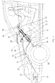
- Fig. 1 is a partial cross-sectional view of a steering wheel retracting device used in vehicle in accordance with the first embodiment of the present invention;
- Fig. 2 is an enlarged partial cross-sectional view of the steering wheel retracting device shown in Fig. 1;
- Fig. 3 is a further enlarged partial cross-sectional view of the steering wheel retracting device shown in Fig. 2;
- Fig. 4 is a partial perspective of the steering wheel retracting device shown in Fig. 1;
- Fig. 5 is a partial exploded view of the steering wheel retracting device shown in Fig. 4;
- Fig. 6 is a partial cross-sectional view similar to Fig. 1, illustrating the operation of the steering wheel retracting device;
- Fig. 7 is an enlarged partial cross-sectional view similar to Fig. 2, illustrating the operation of the steering wheel retracting device;
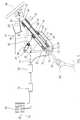
- Fig. 8 is a partial perspective view of a steering wheel retracting device according to the second embodiment of the present invention; and
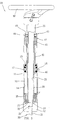
- Fig. 9 is a partial perspective view of a steering wheel retracting device according to the third embodiment of the present invention.
- Referring to the drawings and, initially, to Figs. 1 through 5, in accordance with the present invention, a steering
wheel retracting device 10 is attached to avehicle 80 such as attached to asteering wheel 88 of thevehicle 80 for selectively retracting thesteering wheel 88 of the vehicle when thevehicle 80 hits or is hit by another object, thus preventing a driver from hitting thesteering wheel 88 in the car accident. Thevehicle 80 may further include aframe 81 disposed therein in front of the driver for supporting the steeringwheel retracting device 10. - The steering
wheel retracting device 10 includes acylinder housing 11 secured to thevehicle 80. For example, thecylinder housing 11 includes abase member 12 secured to thevehicle 80 such as secured to theframe 81 of thevehicle 80 with one ormore fasteners 13. Thecylinder housing 11 includes achamber 14 defined therein. Ashaft 20 is rotationally and movably inserted through thechamber 14 of thecylinder housing 11, and includes alower portion 21 extensible out of thechamber 14 of thecylinder housing 11 and anupper portion 22 secured to thesteering wheel 88 of thevehicle 80, for allowing thesteering wheel 88 and theshaft 20 to be rotated and moved downwards relative to thecylinder housing 11 and thevehicle 80. - The
shaft 20 includes abore 23 defined therein and one or moreguiding ribs 24 formed in thelower portion 21 thereof and extending into thebore 23 thereof. One ofmore bearings 25 may be provided between thecylinder housing 11 and thelower portion 21 of theshaft 20 for allowing the rotation and downward movement of theshaft 20 relative to thecylinder housing 11. Atypical coupling device 30 is coupled to thefront wheels 82 of thevehicle 80 for controlling or maneuvering or steering thefront wheels 82. Thecoupling device 30 includes alink 31 of coupling to theshaft 20, and includes one or more guiding ribs orteeth 32 formed or provided on theupper portion 33 thereof for engagement with the guidingribs 24 of theshaft 20 and for allowing the controlling or maneuvering or steering or rotation of thefront wheels 82 by thesteering wheel 88. Theupper portion 33 of thelink 31 can thus be partially inserted in thebore 23 of theshaft 20. Thecoupling device 30 is typical and will not be described in detail. - In operation, as shown in Figs. 1 through 3, when the guiding ribs or
teeth 32 of thelink 31 of thecoupling device 30 are engaged with the guidingribs 24 of theshaft 20, thefront wheels 82 may be controlled or maneuvered or steered or rotated by thesteering wheel 88. This condition may occur when thesteering wheel 88 and theshaft 20 have been retracted or moved downwards relative to thecylinder housing 11 and thevehicle 80. - A
piston rod 40 is movably mounted on theshaft 20. Apiston 41 is formed at a lower portion of thepiston rod 40. Thepiston 41 is movable in thechamber 14 of thecylinder housing 11 for separating thechamber 14 of thecylinder housing 11 into afirst space 16 and a second space 17 (Figs. 2, 3 and 7). A bearingdevice 42 is provided between anupper portion 46 of thepiston rod 40 and theupper portion 22 of theshaft 20. The bearingdevice 42 includes a clamping or retainingring 43 provided between thepiston rod 40 and theshaft 20 for rotationally coupling thepiston rod 40 to theshaft 20 but for preventing the longitudinally or axial movement of thepiston rod 40 relative to theshaft 20. A peripheral groove 26 (Fig. 5) may be defined in theupper portion 22 of theshaft 20 for receiving the clamping or retainingring 43. - The bearing
device 42 may include one ormore thrust bearings 44 and/or one ormore needle bearings 45 provided between thepiston rod 40 and theshaft 20 for facilitating the rotation of thepiston rod 40 on theshaft 20 but for preventing the longitudinal or axial movement of thepiston rod 40 on theshaft 20. In operation, when thefront wheels 82 are controlled or maneuvered or steered or rotated by thesteering wheel 88 and theshaft 20, theshaft 20 may be rotated relative to thecylinder housing 11 and thevehicle 80, and the rotation of thepiston rod 40 relative to thecylinder housing 11 and the vehicle is not required. - The
upper portion 46 of thepiston rod 40 may be temporarily coupled to theframe 81 of thevehicle 80 with one ormore latches 47 for example (Figs. 4 and 5). The breakable latches 47 may be selectively released when thepiston rod 40 and thesteering wheel 88 and theshaft 20 are moved or retracted relative to thecylinder housing 11 and thevehicle 80 for example in a car accident. The operation or retraction of thepiston rod 40 relative to thecylinder housing 11 will be discussed hereinafter. - One or more cylinders or
actuators 50 are attached to the external peripheral portion of thevehicle 80. Eachactuator 50 includes apiston rod 51 extending outwards. Thepiston rod 51 extends outwards from thevehicle 80 for allowing the actuation of theactuators 50 when thevehicle 80 hits or is hit by another object. One ormore check valves 52 and one ormore relief valves 53 may be coupled to theactuator 50 with one ormore hoses 54. The check valve orvalves 52 are coupled to one ormore inlets 18 of thecylinder housing 11. The inlet orinlets 18 are in communication with thesecond space 17 of thecylinder housing 11 for supplying pressurized fluid into thesecond space 17 of thecylinder housing 11 and for retracting thepiston rod 40 relative to thecylinder housing 11. The fluid include but not limited to air, any other proper gas or hydraulic oil. - In operation, in a car accident, i.e., when the
vehicle 80 hits or is hit by another object, theactuators 50 may be operated to supply the pressurized fluid into the second space of thecylinder housing 11 and thus retract thepiston rod 40 relative to thecylinder housing 11. Thus, thesteering wheel 88 is retracted relative to thevehicle 80 and moved away from the driver. Accordingly, the distance between the driver and thesteering wheel 88 is increased, thus preventing the driver from hitting thesteering wheel 88 or cushioning driver in a car accident. The increasing of the distance between the driver and thesteering wheel 88 might reduces the force applied to the driver by the air bag 83 (Fig. 6). - A further cylinder or actuating
device 60 may be secured to thevehicle 80 such as theframe 81 of thevehicle 80 with a pivot coupler 84 (Fig. 5). Theactuating device 60 includes apiston rod 61 coupled to thecylinder housing 11 for further retracting thesteering wheel 88 relative to thevehicle 80, away from the driver, thus further increasing the distance between the driver and thesteering wheel 88. Thelatches 47 may be arranged to be selectively released when thepiston rod 40 and thesteering wheel 88 and theshaft 20 are retracted relative to thecylinder housing 11 and thevehicle 80. - Typical vehicles fail to provide any means for retracting the
steering wheel 88 relative to thevehicle 80 and/or the driver such as moving thesteering wheel 88 downwards and/or forwards relative to thevehicle 80 and/or the driver for increasing the distance between the driver and thesteering wheel 88, thus preventing the driver from quickly hitting thesteering wheel 88. - Accordingly, a vehicle may be provided with the steering wheel retracting device in accordance with the present invention for retracting the steering wheel of the vehicle and/or moving the steering wheel away from the driver when the vehicle hits or is hit by another object, thus preventing the driver from hitting the steering wheel in a car accident.
- Referring to Fig. 8, a steering
wheel retracting device 10 according to a second embodiment of the present invention is shown. The second embodiment is like the first embodiment except several things. Firstly, asleeve 90 is used instead of thecylinder housing 11. Thepiston rod 40 is movably inserted through thesleeve 90. Secondly, there are twocables 91 each including an end connected to theupper portion 46 of thepiston rod 40 and another end connected to theactuator 50. Each of thecables 91 is wound on a pulley attached to thebase element 12. In a car accident, theactuator 50 pulls thecables 91 that in turn lower thepiston rod 40 and selectively release thelatch 47. Thepiston rod 40 is lowered relative to thesleeve 90 so that thesteering wheel 88 and theshaft 20 are retracted relative to thesleeve 90, away from the driver. - Referring to Fig. 9, a steering
wheel retracting device 10 according to a third embodiment of the present invention is shown. The third embodiment is like the second embodiment except only one thing. Firstly, twocables 95 are used instead of thecables 91. Each of thecables 95 includes an upper end connected to thepiston rod 40 and a lower end connected to theframe 81. The lower end of each of thecables 95 may be connected to thesleeve 90 or thebase element 12 in another embodiment. Secondly, each of thecables 95 is wound around a pulley attached to thepiston rod 61. - In a car accident, the
actuating device 60 is operated to retract thepiston rod 61. The pulleys are moved towards the actuatingdevice 60 so that thepiston rod 40 is lowered relative to thesleeve 90, thus releasing thelatch 47. Thus, thesteering wheel 88 is retracted relative to thesleeve 90 and thevehicle 80, away from the driver. - In the first, second and third embodiments, the operation of the
actuator 50 and/or theactuating device 60 may be controlled by a circuit for controlling the inflation of theair bag 83. When the inflation of theair bag 83 begins, the operation of theactuator 50 and/or theactuating device 60 begins. - The present invention has been described via the detailed illustration of the embodiments. Those skilled in the art can derive variations from the embodiments without departing from the scope of the present invention. Therefore, the embodiments shall not limit the scope of the present invention defined in the claims.
Claims (8)
- A steering wheel retracting device comprising:a steering wheel provided in a vehicle; andmeans for moving said steering wheel relative to said vehicle to selectively move said steering wheel away from a driver in a car accident.
- The steering wheel retracting device according to claim 1 wherein said moving means comprises:a cylinder housing being attached to said vehicle and comprising a chamber defined therein; anda shaft inserted through said chamber of said cylinder housing and formed with an upper portion attached to said steering wheel.
- The steering wheel retracting device according to claim 2 comprising a coupling device for coupling said steering wheel to front wheels of said vehicle, wherein said coupling device comprises a link comprising an upper portion connected to said steering wheel and at least one guiding rib formed on said upper portion, and said shaft comprises a bore for receiving said link and at least one guiding formed on the wall of the bore for engagement with said guiding rib of said link so that said link can be rotated by said shaft.
- The steering wheel retracting device according to claim 2 wherein said moving means comprises:a piston rod movably mounted on said shaft; anda piston connected to said piston rod and movably disposed in said chamber of said cylinder housing, thus separating said chamber of said cylinder housing into a first space and a second space; andan actuator coupled to said second space of said cylinder housing for selectively moving said piston relative to said cylinder housing.
- The steering wheel retracting device according to claim 4 said actuator is operable to transmit pressurized fluid into said second space of said hydraulic cylinder housing.
- The steering wheel retracting device according to claim 1 wherein said moving means comprises an actuating device comprising:a piston rod connected to said hydraulic cylinder housing; anda frame attached to the vehicle for support said actuating device.
- The steering wheel retracting device according to claim 1 wherein said moving means comprises:a sleeve being attached to the vehicle and comprising a chamber defined therein; anda shaft movably inserted through said sleeve and formed with an upper portion connected to said steering wheel.
- The steering wheel retracting device according to claim 7 wherein said moving means comprises:a piston rod for movably receiving said shaft;a piston connected to said piston rod and movably inserted in said chamber of said sleeve; andat least one cable for pulling said piston rod downwards relative to said sleeve.
Applications Claiming Priority (1)
| Application Number | Priority Date | Filing Date | Title |
|---|---|---|---|
| US11/403,765 US20070241548A1 (en) | 2006-04-13 | 2006-04-13 | Steering wheel retracting device for vehicle |
Publications (2)
| Publication Number | Publication Date |
|---|---|
| EP1845006A2 true EP1845006A2 (en) | 2007-10-17 |
| EP1845006A3 EP1845006A3 (en) | 2008-09-03 |
Family
ID=38230304
Family Applications (1)
| Application Number | Title | Priority Date | Filing Date |
|---|---|---|---|
| EP07251435A Withdrawn EP1845006A3 (en) | 2006-04-13 | 2007-03-30 | Steering wheel retracting device for vehicle |
Country Status (6)
| Country | Link |
|---|---|
| US (1) | US20070241548A1 (en) |
| EP (1) | EP1845006A3 (en) |
| JP (1) | JP2007284048A (en) |
| KR (1) | KR20070101767A (en) |
| CN (1) | CN100513239C (en) |
| WO (1) | WO2007118410A1 (en) |
Families Citing this family (53)
| Publication number | Priority date | Publication date | Assignee | Title |
|---|---|---|---|---|
| US7735405B2 (en) * | 2008-03-14 | 2010-06-15 | Autoliv Asp, Inc. | Pyrotechnic actuator for retracting a piston |
| DE102012014762A1 (en) * | 2012-07-25 | 2014-01-30 | Audi Ag | Motor vehicle with retractable steering wheel |
| EP2907730B1 (en) | 2014-01-29 | 2017-09-06 | Steering Solutions IP Holding Corporation | Hands on steering wheel detect |
| US10351159B2 (en) * | 2015-05-01 | 2019-07-16 | Steering Solutions Ip Holding Corporation | Retractable steering column with a radially projecting attachment |
| US10589774B2 (en) | 2015-05-01 | 2020-03-17 | Steering Solutions Ip Holding Corporation | Counter rotation steering wheel |
| US9919724B2 (en) | 2015-05-29 | 2018-03-20 | Steering Solutions Ip Holding Corporation | Retractable steering column with manual retrieval |
| US10343706B2 (en) | 2015-06-11 | 2019-07-09 | Steering Solutions Ip Holding Corporation | Retractable steering column system, vehicle having the same, and method |
| US11560169B2 (en) | 2015-06-11 | 2023-01-24 | Steering Solutions Ip Holding Corporation | Retractable steering column system and method |
| DE102016110791A1 (en) | 2015-06-15 | 2016-12-15 | Steering Solutions Ip Holding Corporation | Gesture control for a retractable steering wheel |
| CN106256651B (en) | 2015-06-16 | 2019-06-04 | 操纵技术Ip控股公司 | Retractable steering column assembly and method |
| US9828016B2 (en) | 2015-06-24 | 2017-11-28 | Steering Solutions Ip Holding Corporation | Retractable steering column system, vehicle having the same, and method |
| US20160375931A1 (en) | 2015-06-25 | 2016-12-29 | Steering Solutions Ip Holding Corporation | Rotation control system for a steering wheel and method |
| DE102016111473A1 (en) | 2015-06-25 | 2016-12-29 | Steering Solutions Ip Holding Corporation | STATIONARY STEERING WHEEL ASSEMBLY AND METHOD |
| US10112639B2 (en) | 2015-06-26 | 2018-10-30 | Steering Solutions Ip Holding Corporation | Vehicle steering arrangement and method of making same |
| US9944307B2 (en) | 2015-06-26 | 2018-04-17 | Steering Solutions Ip Holding Corporation | Steering assembly and method of monitoring a space within vehicle |
| US9840271B2 (en) | 2015-06-29 | 2017-12-12 | Steering Solutions Ip Holding Corporation | Retractable steering column with rake limiter |
| US9845103B2 (en) | 2015-06-29 | 2017-12-19 | Steering Solutions Ip Holding Corporation | Steering arrangement |
| US9849904B2 (en) | 2015-07-31 | 2017-12-26 | Steering Solutions Ip Holding Corporation | Retractable steering column with dual actuators |
| US9845106B2 (en) | 2015-08-31 | 2017-12-19 | Steering Solutions Ip Holding Corporation | Overload protection for belt drive mechanism |
| US10160472B2 (en) | 2015-10-20 | 2018-12-25 | Steering Solutions Ip Holding Corporation | Steering column with stationary hub |
| US9809155B2 (en) | 2015-10-27 | 2017-11-07 | Steering Solutions Ip Holding Corporation | Retractable steering column assembly having lever, vehicle having retractable steering column assembly, and method |
| US10029725B2 (en) | 2015-12-03 | 2018-07-24 | Steering Solutions Ip Holding Corporation | Torque feedback system for a steer-by-wire vehicle, vehicle having steering column, and method of providing feedback in vehicle |
| US10207697B2 (en) * | 2015-12-21 | 2019-02-19 | Ford Global Technologies, Llc | Movable steering wheel for autonomous vehicle |
| US10322682B2 (en) | 2016-03-03 | 2019-06-18 | Steering Solutions Ip Holding Corporation | Steering wheel with keyboard |
| US10496102B2 (en) | 2016-04-11 | 2019-12-03 | Steering Solutions Ip Holding Corporation | Steering system for autonomous vehicle |
| DE102017108692B4 (en) | 2016-04-25 | 2024-09-26 | Steering Solutions Ip Holding Corporation | Control of an electric power steering system using system state predictions |
| US10351161B2 (en) | 2016-05-27 | 2019-07-16 | Steering Solutions Ip Holding Corporation | Steering column with manual retraction |
| CN107521547B (en) | 2016-06-21 | 2020-03-10 | 操纵技术Ip控股公司 | Self-locking telescopic actuator for steering column assembly |
| US10457313B2 (en) | 2016-06-28 | 2019-10-29 | Steering Solutions Ip Holding Corporation | ADAS wheel locking device |
| US10363958B2 (en) | 2016-07-26 | 2019-07-30 | Steering Solutions Ip Holding Corporation | Electric power steering mode determination and transitioning |
| US10160477B2 (en) | 2016-08-01 | 2018-12-25 | Steering Solutions Ip Holding Corporation | Electric power steering column assembly |
| US10189496B2 (en) | 2016-08-22 | 2019-01-29 | Steering Solutions Ip Holding Corporation | Steering assembly having a telescope drive lock assembly |
| US10384708B2 (en) | 2016-09-12 | 2019-08-20 | Steering Solutions Ip Holding Corporation | Intermediate shaft assembly for steer-by-wire steering system |
| US10160473B2 (en) | 2016-09-13 | 2018-12-25 | Steering Solutions Ip Holding Corporation | Steering column decoupling system |
| US10144383B2 (en) | 2016-09-29 | 2018-12-04 | Steering Solutions Ip Holding Corporation | Steering wheel with video screen and airbag |
| US10399591B2 (en) | 2016-10-03 | 2019-09-03 | Steering Solutions Ip Holding Corporation | Steering compensation with grip sensing |
| US10239552B2 (en) | 2016-10-14 | 2019-03-26 | Steering Solutions Ip Holding Corporation | Rotation control assembly for a steering column |
| US10481602B2 (en) | 2016-10-17 | 2019-11-19 | Steering Solutions Ip Holding Corporation | Sensor fusion for autonomous driving transition control |
| US10310605B2 (en) | 2016-11-15 | 2019-06-04 | Steering Solutions Ip Holding Corporation | Haptic feedback for steering system controls |
| US10421475B2 (en) | 2016-11-15 | 2019-09-24 | Steering Solutions Ip Holding Corporation | Electric actuator mechanism for retractable steering column assembly with manual override |
| US9862403B1 (en) | 2016-11-29 | 2018-01-09 | Steering Solutions Ip Holding Corporation | Manually retractable steering column assembly for autonomous vehicle |
| US10351160B2 (en) | 2016-11-30 | 2019-07-16 | Steering Solutions Ip Holding Corporation | Steering column assembly having a sensor assembly |
| US10780915B2 (en) | 2016-12-07 | 2020-09-22 | Steering Solutions Ip Holding Corporation | Vehicle steering system having a user experience based automated driving to manual driving transition system and method |
| US10370022B2 (en) | 2017-02-13 | 2019-08-06 | Steering Solutions Ip Holding Corporation | Steering column assembly for autonomous vehicle |
| US10385930B2 (en) | 2017-02-21 | 2019-08-20 | Steering Solutions Ip Holding Corporation | Ball coupling assembly for steering column assembly |
| US10449927B2 (en) | 2017-04-13 | 2019-10-22 | Steering Solutions Ip Holding Corporation | Steering system having anti-theft capabilities |
| EP3486140B1 (en) | 2017-11-20 | 2021-01-20 | Steering Solutions IP Holding Corporation | Vision based active steering system |
| US10875566B2 (en) | 2018-03-22 | 2020-12-29 | Steering Solutions Ip Holding Corporation | Stow release assembly for a manually adjustable steering column assembly |
| US10974756B2 (en) | 2018-07-31 | 2021-04-13 | Steering Solutions Ip Holding Corporation | Clutch device latching system and method |
| KR102659231B1 (en) * | 2018-11-09 | 2024-04-18 | 현대자동차주식회사 | Device of steering column for working together airbag system |
| US11061401B2 (en) * | 2019-10-29 | 2021-07-13 | Ford Global Technologies, Llc | Stowable steering wheel for autonomous vehicles |
| CN111891209A (en) * | 2020-07-30 | 2020-11-06 | 盐城同济汽车配件有限公司 | Electric steering wheel adjusting system |
| CN114852162A (en) * | 2022-03-25 | 2022-08-05 | 盐城工业职业技术学院 | Novel electric steering mechanism of agricultural tractor |
Family Cites Families (20)
| Publication number | Priority date | Publication date | Assignee | Title |
|---|---|---|---|---|
| GB1528908A (en) * | 1974-11-04 | 1978-10-18 | Cam Gears Ltd | Vehicle safety system |
| JPS5160030U (en) * | 1974-11-06 | 1976-05-12 | ||
| JPS565269A (en) * | 1979-06-25 | 1981-01-20 | Toyota Motor Corp | Steering device |
| JPS59142172U (en) * | 1983-03-14 | 1984-09-22 | トヨタ自動車株式会社 | Telescopic steering device |
| DE3544345C2 (en) * | 1984-12-24 | 1994-03-31 | Volkswagen Ag | Safety steering column for motor vehicles |
| US4674354A (en) * | 1985-10-15 | 1987-06-23 | Brand Harold E | Collapsible steering column |
| US4966391A (en) * | 1987-04-15 | 1990-10-30 | Agajanian's Ascot Slic Trac, Inc. | Impact-absorbing amusement vehicle |
| JPS63306967A (en) * | 1987-06-08 | 1988-12-14 | Nissan Motor Co Ltd | Steering column displacement mechanism for automobile |
| DE3930372A1 (en) * | 1989-09-12 | 1991-03-21 | Stabilus Gmbh | HYDROPNEUMATIC ADJUSTMENT |
| US5070741A (en) * | 1990-12-21 | 1991-12-10 | Ford Motor Company | Large collapse mini-steering column |
| DE4225671A1 (en) * | 1992-08-04 | 1994-02-10 | Bayerische Motoren Werke Ag | Steering column of a motor vehicle with a retraction device for the end region on the steering wheel side |
| DE4235588A1 (en) * | 1992-10-22 | 1994-04-28 | Stabilus Gmbh | Hydropneumatic adjustment element |
| FR2705635B1 (en) * | 1993-05-24 | 1995-08-25 | Peugeot | Retraction system, in the event of an impact, of a telescopic steering column for a vehicle. |
| GB9817536D0 (en) * | 1998-08-13 | 1998-10-07 | Rover Group | A motor vehicle |
| DE10039792A1 (en) * | 2000-08-16 | 2002-02-28 | Daimler Chrysler Ag | Steering column for a motor vehicle |
| DE10100726A1 (en) * | 2001-01-10 | 2002-07-11 | Suspa Holding Gmbh | steering damper |
| JP2002274394A (en) * | 2001-03-14 | 2002-09-25 | Nsk Ltd | Retractable steering column device |
| US6916044B2 (en) * | 2003-07-08 | 2005-07-12 | Daimlerchrysler Corporation | Steering column/airbag tunable impact absorption system |
| JP2005193833A (en) * | 2004-01-09 | 2005-07-21 | Mazda Motor Corp | Vehicle steering device |
| US20060131865A1 (en) * | 2004-12-22 | 2006-06-22 | Wasek Gregory A | Steering assembly and method of operating the same |
-
2006
- 2006-04-13 US US11/403,765 patent/US20070241548A1/en not_active Abandoned
-
2007
- 2007-03-29 JP JP2007087098A patent/JP2007284048A/en active Pending
- 2007-03-29 KR KR1020070030600A patent/KR20070101767A/en not_active Abandoned
- 2007-03-30 EP EP07251435A patent/EP1845006A3/en not_active Withdrawn
- 2007-03-30 CN CNB2007100936401A patent/CN100513239C/en not_active Expired - Fee Related
- 2007-04-09 WO PCT/CN2007/001139 patent/WO2007118410A1/en not_active Ceased
Non-Patent Citations (1)
| Title |
|---|
| None |
Also Published As
| Publication number | Publication date |
|---|---|
| US20070241548A1 (en) | 2007-10-18 |
| JP2007284048A (en) | 2007-11-01 |
| WO2007118410A1 (en) | 2007-10-25 |
| KR20070101767A (en) | 2007-10-17 |
| CN100513239C (en) | 2009-07-15 |
| EP1845006A3 (en) | 2008-09-03 |
| CN101054091A (en) | 2007-10-17 |
Similar Documents
| Publication | Publication Date | Title |
|---|---|---|
| EP1845006A2 (en) | Steering wheel retracting device for vehicle | |
| US7793980B2 (en) | Retractable steering mechanism | |
| DE10053182B4 (en) | Telescopic vehicle steering column device | |
| US6942261B2 (en) | Linear actuator with an internal dampening mechanism | |
| US7182191B2 (en) | Motion damper | |
| US6244128B1 (en) | Steering wheel impact positioning system | |
| JPH0583421B2 (en) | ||
| US8020584B2 (en) | Variable valve for impact dispersal device | |
| US7597166B2 (en) | Hinge device for pedestrian protection system | |
| CN116262516B (en) | Automatic storage column | |
| US6158556A (en) | Vehicle safety mechanism for dissipating collision forces | |
| EP1877286B1 (en) | Impact dispersal device | |
| CN111169526B (en) | Steering column device working in combination with airbag system | |
| CN113710509B (en) | Traction and mining machinery | |
| US6916044B2 (en) | Steering column/airbag tunable impact absorption system | |
| CN101372238B (en) | Automatic Steering Wheel Crushing Device | |
| EP2048059B1 (en) | Automatically collapsible device for steering wheel | |
| CN101289094A (en) | Automatic collapsing device for steering wheel | |
| EP4552919B1 (en) | Gas cylinder and the use of such gas cylinder | |
| US20250178560A1 (en) | Vehicle Hood Lifter and Airbag Assembly | |
| TWI328541B (en) | ||
| CN120246067A (en) | Automobile steering column and vehicle | |
| TW200840749A (en) | Steering wheel with automatic crumbling and contracting device | |
| TW200610674A (en) | A protection structure for car |
Legal Events
| Date | Code | Title | Description |
|---|---|---|---|
| PUAI | Public reference made under article 153(3) epc to a published international application that has entered the european phase |
Free format text: ORIGINAL CODE: 0009012 |
|
| 17P | Request for examination filed |
Effective date: 20070413 |
|
| AK | Designated contracting states |
Kind code of ref document: A2 Designated state(s): AT BE BG CH CY CZ DE DK EE ES FI FR GB GR HU IE IS IT LI LT LU LV MC MT NL PL PT RO SE SI SK TR |
|
| AX | Request for extension of the european patent |
Extension state: AL BA HR MK YU |
|
| PUAL | Search report despatched |
Free format text: ORIGINAL CODE: 0009013 |
|
| AK | Designated contracting states |
Kind code of ref document: A3 Designated state(s): AT BE BG CH CY CZ DE DK EE ES FI FR GB GR HU IE IS IT LI LT LU LV MC MT NL PL PT RO SE SI SK TR |
|
| AX | Request for extension of the european patent |
Extension state: AL BA HR MK RS |
|
| AKX | Designation fees paid |
Designated state(s): AT BE BG CH CY CZ DE DK EE ES FI FR GB GR HU IE IS IT LI LT LU LV MC MT NL PL PT RO SE SI SK TR |
|
| 17Q | First examination report despatched |
Effective date: 20090408 |
|
| STAA | Information on the status of an ep patent application or granted ep patent |
Free format text: STATUS: THE APPLICATION IS DEEMED TO BE WITHDRAWN |
|
| 18D | Application deemed to be withdrawn |
Effective date: 20091219 |