EP1844844A2 - Catalytic reactor - Google Patents
Catalytic reactor Download PDFInfo
- Publication number
- EP1844844A2 EP1844844A2 EP07251530A EP07251530A EP1844844A2 EP 1844844 A2 EP1844844 A2 EP 1844844A2 EP 07251530 A EP07251530 A EP 07251530A EP 07251530 A EP07251530 A EP 07251530A EP 1844844 A2 EP1844844 A2 EP 1844844A2
- Authority
- EP
- European Patent Office
- Prior art keywords
- tube
- fluid
- catalytic
- tubes
- conduit
- Prior art date
- Legal status (The legal status is an assumption and is not a legal conclusion. Google has not performed a legal analysis and makes no representation as to the accuracy of the status listed.)
- Granted
Links
- 230000003197 catalytic effect Effects 0.000 title claims abstract description 105
- 239000012530 fluid Substances 0.000 claims abstract description 123
- 239000003054 catalyst Substances 0.000 claims abstract description 65
- 230000008859 change Effects 0.000 claims abstract description 17
- 230000003647 oxidation Effects 0.000 claims abstract description 16
- 238000007254 oxidation reaction Methods 0.000 claims abstract description 16
- 239000000446 fuel Substances 0.000 claims description 40
- 239000000203 mixture Substances 0.000 claims description 31
- 238000002156 mixing Methods 0.000 claims description 15
- 238000000034 method Methods 0.000 claims description 13
- 229930195733 hydrocarbon Natural products 0.000 claims description 10
- 150000002430 hydrocarbons Chemical class 0.000 claims description 10
- 239000004215 Carbon black (E152) Substances 0.000 claims description 9
- 238000006555 catalytic reaction Methods 0.000 claims description 9
- 230000009977 dual effect Effects 0.000 claims description 2
- 230000000737 periodic effect Effects 0.000 claims description 2
- 230000037361 pathway Effects 0.000 claims 2
- 239000003570 air Substances 0.000 description 35
- 238000002485 combustion reaction Methods 0.000 description 17
- 238000006243 chemical reaction Methods 0.000 description 15
- 229910002089 NOx Inorganic materials 0.000 description 10
- MWUXSHHQAYIFBG-UHFFFAOYSA-N Nitric oxide Chemical compound O=[N] MWUXSHHQAYIFBG-UHFFFAOYSA-N 0.000 description 9
- 238000001816 cooling Methods 0.000 description 9
- 239000000463 material Substances 0.000 description 6
- 239000000758 substrate Substances 0.000 description 6
- 239000007789 gas Substances 0.000 description 5
- IJGRMHOSHXDMSA-UHFFFAOYSA-N Atomic nitrogen Chemical compound N#N IJGRMHOSHXDMSA-UHFFFAOYSA-N 0.000 description 4
- XEEYBQQBJWHFJM-UHFFFAOYSA-N Iron Chemical compound [Fe] XEEYBQQBJWHFJM-UHFFFAOYSA-N 0.000 description 4
- PXHVJJICTQNCMI-UHFFFAOYSA-N Nickel Chemical compound [Ni] PXHVJJICTQNCMI-UHFFFAOYSA-N 0.000 description 4
- 230000015572 biosynthetic process Effects 0.000 description 4
- 238000000576 coating method Methods 0.000 description 4
- 230000007423 decrease Effects 0.000 description 4
- 230000036961 partial effect Effects 0.000 description 4
- 230000009467 reduction Effects 0.000 description 4
- MGWGWNFMUOTEHG-UHFFFAOYSA-N 4-(3,5-dimethylphenyl)-1,3-thiazol-2-amine Chemical compound CC1=CC(C)=CC(C=2N=C(N)SC=2)=C1 MGWGWNFMUOTEHG-UHFFFAOYSA-N 0.000 description 3
- UGFAIRIUMAVXCW-UHFFFAOYSA-N Carbon monoxide Chemical compound [O+]#[C-] UGFAIRIUMAVXCW-UHFFFAOYSA-N 0.000 description 3
- QVGXLLKOCUKJST-UHFFFAOYSA-N atomic oxygen Chemical compound [O] QVGXLLKOCUKJST-UHFFFAOYSA-N 0.000 description 3
- 239000011248 coating agent Substances 0.000 description 3
- 238000004519 manufacturing process Methods 0.000 description 3
- 229910044991 metal oxide Inorganic materials 0.000 description 3
- 150000004706 metal oxides Chemical class 0.000 description 3
- JCXJVPUVTGWSNB-UHFFFAOYSA-N nitrogen dioxide Inorganic materials O=[N]=O JCXJVPUVTGWSNB-UHFFFAOYSA-N 0.000 description 3
- 239000001301 oxygen Substances 0.000 description 3
- 229910052760 oxygen Inorganic materials 0.000 description 3
- 230000002028 premature Effects 0.000 description 3
- 230000008569 process Effects 0.000 description 3
- CURLTUGMZLYLDI-UHFFFAOYSA-N Carbon dioxide Chemical compound O=C=O CURLTUGMZLYLDI-UHFFFAOYSA-N 0.000 description 2
- VYZAMTAEIAYCRO-UHFFFAOYSA-N Chromium Chemical compound [Cr] VYZAMTAEIAYCRO-UHFFFAOYSA-N 0.000 description 2
- CPLXHLVBOLITMK-UHFFFAOYSA-N Magnesium oxide Chemical compound [Mg]=O CPLXHLVBOLITMK-UHFFFAOYSA-N 0.000 description 2
- KDLHZDBZIXYQEI-UHFFFAOYSA-N Palladium Chemical compound [Pd] KDLHZDBZIXYQEI-UHFFFAOYSA-N 0.000 description 2
- VYPSYNLAJGMNEJ-UHFFFAOYSA-N Silicium dioxide Chemical compound O=[Si]=O VYPSYNLAJGMNEJ-UHFFFAOYSA-N 0.000 description 2
- GWEVSGVZZGPLCZ-UHFFFAOYSA-N Titan oxide Chemical compound O=[Ti]=O GWEVSGVZZGPLCZ-UHFFFAOYSA-N 0.000 description 2
- MCMNRKCIXSYSNV-UHFFFAOYSA-N Zirconium dioxide Chemical compound O=[Zr]=O MCMNRKCIXSYSNV-UHFFFAOYSA-N 0.000 description 2
- PNEYBMLMFCGWSK-UHFFFAOYSA-N aluminium oxide Inorganic materials [O-2].[O-2].[O-2].[Al+3].[Al+3] PNEYBMLMFCGWSK-UHFFFAOYSA-N 0.000 description 2
- 229910002090 carbon oxide Inorganic materials 0.000 description 2
- 229910052804 chromium Inorganic materials 0.000 description 2
- 239000011651 chromium Substances 0.000 description 2
- 229910017052 cobalt Inorganic materials 0.000 description 2
- 239000010941 cobalt Substances 0.000 description 2
- GUTLYIVDDKVIGB-UHFFFAOYSA-N cobalt atom Chemical compound [Co] GUTLYIVDDKVIGB-UHFFFAOYSA-N 0.000 description 2
- 239000012809 cooling fluid Substances 0.000 description 2
- 230000003247 decreasing effect Effects 0.000 description 2
- 230000000694 effects Effects 0.000 description 2
- 239000003344 environmental pollutant Substances 0.000 description 2
- 239000001257 hydrogen Substances 0.000 description 2
- 229910052739 hydrogen Inorganic materials 0.000 description 2
- 150000002431 hydrogen Chemical class 0.000 description 2
- 229910052742 iron Inorganic materials 0.000 description 2
- 229910052759 nickel Inorganic materials 0.000 description 2
- 229910052757 nitrogen Inorganic materials 0.000 description 2
- 230000001590 oxidative effect Effects 0.000 description 2
- BASFCYQUMIYNBI-UHFFFAOYSA-N platinum Chemical compound [Pt] BASFCYQUMIYNBI-UHFFFAOYSA-N 0.000 description 2
- 231100000719 pollutant Toxicity 0.000 description 2
- 230000001737 promoting effect Effects 0.000 description 2
- 239000000126 substance Substances 0.000 description 2
- XLYOFNOQVPJJNP-UHFFFAOYSA-N water Substances O XLYOFNOQVPJJNP-UHFFFAOYSA-N 0.000 description 2
- 229910001868 water Inorganic materials 0.000 description 2
- 229910052684 Cerium Inorganic materials 0.000 description 1
- RYGMFSIKBFXOCR-UHFFFAOYSA-N Copper Chemical compound [Cu] RYGMFSIKBFXOCR-UHFFFAOYSA-N 0.000 description 1
- 241000249931 Doronicum maximum Species 0.000 description 1
- 229910000990 Ni alloy Inorganic materials 0.000 description 1
- CBENFWSGALASAD-UHFFFAOYSA-N Ozone Chemical compound [O-][O+]=O CBENFWSGALASAD-UHFFFAOYSA-N 0.000 description 1
- KJTLSVCANCCWHF-UHFFFAOYSA-N Ruthenium Chemical compound [Ru] KJTLSVCANCCWHF-UHFFFAOYSA-N 0.000 description 1
- QCWXUUIWCKQGHC-UHFFFAOYSA-N Zirconium Chemical compound [Zr] QCWXUUIWCKQGHC-UHFFFAOYSA-N 0.000 description 1
- 238000003916 acid precipitation Methods 0.000 description 1
- 230000002411 adverse Effects 0.000 description 1
- 238000013019 agitation Methods 0.000 description 1
- 229910045601 alloy Inorganic materials 0.000 description 1
- 239000000956 alloy Substances 0.000 description 1
- 238000005275 alloying Methods 0.000 description 1
- 229910052782 aluminium Inorganic materials 0.000 description 1
- XAGFODPZIPBFFR-UHFFFAOYSA-N aluminium Chemical compound [Al] XAGFODPZIPBFFR-UHFFFAOYSA-N 0.000 description 1
- 239000012080 ambient air Substances 0.000 description 1
- 230000000712 assembly Effects 0.000 description 1
- 238000000429 assembly Methods 0.000 description 1
- 239000010953 base metal Substances 0.000 description 1
- 230000009286 beneficial effect Effects 0.000 description 1
- 229910002092 carbon dioxide Inorganic materials 0.000 description 1
- 239000001569 carbon dioxide Substances 0.000 description 1
- 229910002091 carbon monoxide Inorganic materials 0.000 description 1
- 238000007084 catalytic combustion reaction Methods 0.000 description 1
- 239000000919 ceramic Substances 0.000 description 1
- GWXLDORMOJMVQZ-UHFFFAOYSA-N cerium Chemical compound [Ce] GWXLDORMOJMVQZ-UHFFFAOYSA-N 0.000 description 1
- 238000003889 chemical engineering Methods 0.000 description 1
- UOUJSJZBMCDAEU-UHFFFAOYSA-N chromium(3+);oxygen(2-) Chemical class [O-2].[O-2].[O-2].[Cr+3].[Cr+3] UOUJSJZBMCDAEU-UHFFFAOYSA-N 0.000 description 1
- IVMYJDGYRUAWML-UHFFFAOYSA-N cobalt(ii) oxide Chemical class [Co]=O IVMYJDGYRUAWML-UHFFFAOYSA-N 0.000 description 1
- 238000004891 communication Methods 0.000 description 1
- 239000004020 conductor Substances 0.000 description 1
- 229910052802 copper Inorganic materials 0.000 description 1
- 239000010949 copper Substances 0.000 description 1
- 230000001419 dependent effect Effects 0.000 description 1
- 238000009792 diffusion process Methods 0.000 description 1
- 230000006872 improvement Effects 0.000 description 1
- 230000002401 inhibitory effect Effects 0.000 description 1
- 229910052741 iridium Inorganic materials 0.000 description 1
- GKOZUEZYRPOHIO-UHFFFAOYSA-N iridium atom Chemical compound [Ir] GKOZUEZYRPOHIO-UHFFFAOYSA-N 0.000 description 1
- 229910052747 lanthanoid Inorganic materials 0.000 description 1
- 150000002602 lanthanoids Chemical class 0.000 description 1
- 229910052746 lanthanum Inorganic materials 0.000 description 1
- FZLIPJUXYLNCLC-UHFFFAOYSA-N lanthanum atom Chemical compound [La] FZLIPJUXYLNCLC-UHFFFAOYSA-N 0.000 description 1
- 239000000395 magnesium oxide Substances 0.000 description 1
- WPBNNNQJVZRUHP-UHFFFAOYSA-L manganese(2+);methyl n-[[2-(methoxycarbonylcarbamothioylamino)phenyl]carbamothioyl]carbamate;n-[2-(sulfidocarbothioylamino)ethyl]carbamodithioate Chemical compound [Mn+2].[S-]C(=S)NCCNC([S-])=S.COC(=O)NC(=S)NC1=CC=CC=C1NC(=S)NC(=O)OC WPBNNNQJVZRUHP-UHFFFAOYSA-L 0.000 description 1
- 229910052751 metal Inorganic materials 0.000 description 1
- 239000002184 metal Substances 0.000 description 1
- 150000001247 metal acetylides Chemical class 0.000 description 1
- 229910001092 metal group alloy Inorganic materials 0.000 description 1
- VUZPPFZMUPKLLV-UHFFFAOYSA-N methane;hydrate Chemical compound C.O VUZPPFZMUPKLLV-UHFFFAOYSA-N 0.000 description 1
- 150000004767 nitrides Chemical class 0.000 description 1
- 229910000510 noble metal Inorganic materials 0.000 description 1
- 229910052762 osmium Inorganic materials 0.000 description 1
- SYQBFIAQOQZEGI-UHFFFAOYSA-N osmium atom Chemical compound [Os] SYQBFIAQOQZEGI-UHFFFAOYSA-N 0.000 description 1
- 239000007800 oxidant agent Substances 0.000 description 1
- 238000007353 oxidative pyrolysis Methods 0.000 description 1
- 229910052763 palladium Inorganic materials 0.000 description 1
- 229910052697 platinum Inorganic materials 0.000 description 1
- 230000000135 prohibitive effect Effects 0.000 description 1
- 238000009789 rate limiting process Methods 0.000 description 1
- 239000000376 reactant Substances 0.000 description 1
- 230000035484 reaction time Effects 0.000 description 1
- 230000009257 reactivity Effects 0.000 description 1
- 239000011819 refractory material Substances 0.000 description 1
- 239000003870 refractory metal Substances 0.000 description 1
- 229910052703 rhodium Inorganic materials 0.000 description 1
- 239000010948 rhodium Substances 0.000 description 1
- MHOVAHRLVXNVSD-UHFFFAOYSA-N rhodium atom Chemical compound [Rh] MHOVAHRLVXNVSD-UHFFFAOYSA-N 0.000 description 1
- 229910052707 ruthenium Inorganic materials 0.000 description 1
- 239000000377 silicon dioxide Substances 0.000 description 1
- 230000007704 transition Effects 0.000 description 1
- 229910052720 vanadium Inorganic materials 0.000 description 1
- LEONUFNNVUYDNQ-UHFFFAOYSA-N vanadium atom Chemical compound [V] LEONUFNNVUYDNQ-UHFFFAOYSA-N 0.000 description 1
- 229910052727 yttrium Inorganic materials 0.000 description 1
- VWQVUPCCIRVNHF-UHFFFAOYSA-N yttrium atom Chemical compound [Y] VWQVUPCCIRVNHF-UHFFFAOYSA-N 0.000 description 1
- 229910052726 zirconium Inorganic materials 0.000 description 1
Images



Classifications
-
- B—PERFORMING OPERATIONS; TRANSPORTING
- B01—PHYSICAL OR CHEMICAL PROCESSES OR APPARATUS IN GENERAL
- B01J—CHEMICAL OR PHYSICAL PROCESSES, e.g. CATALYSIS OR COLLOID CHEMISTRY; THEIR RELEVANT APPARATUS
- B01J8/00—Chemical or physical processes in general, conducted in the presence of fluids and solid particles; Apparatus for such processes
- B01J8/02—Chemical or physical processes in general, conducted in the presence of fluids and solid particles; Apparatus for such processes with stationary particles, e.g. in fixed beds
- B01J8/06—Chemical or physical processes in general, conducted in the presence of fluids and solid particles; Apparatus for such processes with stationary particles, e.g. in fixed beds in tube reactors; the solid particles being arranged in tubes
- B01J8/065—Feeding reactive fluids
-
- B—PERFORMING OPERATIONS; TRANSPORTING
- B01—PHYSICAL OR CHEMICAL PROCESSES OR APPARATUS IN GENERAL
- B01D—SEPARATION
- B01D53/00—Separation of gases or vapours; Recovering vapours of volatile solvents from gases; Chemical or biological purification of waste gases, e.g. engine exhaust gases, smoke, fumes, flue gases, aerosols
- B01D53/34—Chemical or biological purification of waste gases
- B01D53/92—Chemical or biological purification of waste gases of engine exhaust gases
- B01D53/94—Chemical or biological purification of waste gases of engine exhaust gases by catalytic processes
- B01D53/9445—Simultaneously removing carbon monoxide, hydrocarbons or nitrogen oxides making use of three-way catalysts [TWC] or four-way-catalysts [FWC]
- B01D53/9454—Simultaneously removing carbon monoxide, hydrocarbons or nitrogen oxides making use of three-way catalysts [TWC] or four-way-catalysts [FWC] characterised by a specific device
-
- B—PERFORMING OPERATIONS; TRANSPORTING
- B01—PHYSICAL OR CHEMICAL PROCESSES OR APPARATUS IN GENERAL
- B01J—CHEMICAL OR PHYSICAL PROCESSES, e.g. CATALYSIS OR COLLOID CHEMISTRY; THEIR RELEVANT APPARATUS
- B01J12/00—Chemical processes in general for reacting gaseous media with gaseous media; Apparatus specially adapted therefor
- B01J12/007—Chemical processes in general for reacting gaseous media with gaseous media; Apparatus specially adapted therefor in the presence of catalytically active bodies, e.g. porous plates
-
- B—PERFORMING OPERATIONS; TRANSPORTING
- B01—PHYSICAL OR CHEMICAL PROCESSES OR APPARATUS IN GENERAL
- B01J—CHEMICAL OR PHYSICAL PROCESSES, e.g. CATALYSIS OR COLLOID CHEMISTRY; THEIR RELEVANT APPARATUS
- B01J15/00—Chemical processes in general for reacting gaseous media with non-particulate solids, e.g. sheet material; Apparatus specially adapted therefor
- B01J15/005—Chemical processes in general for reacting gaseous media with non-particulate solids, e.g. sheet material; Apparatus specially adapted therefor in the presence of catalytically active bodies, e.g. porous plates
-
- B—PERFORMING OPERATIONS; TRANSPORTING
- B01—PHYSICAL OR CHEMICAL PROCESSES OR APPARATUS IN GENERAL
- B01J—CHEMICAL OR PHYSICAL PROCESSES, e.g. CATALYSIS OR COLLOID CHEMISTRY; THEIR RELEVANT APPARATUS
- B01J8/00—Chemical or physical processes in general, conducted in the presence of fluids and solid particles; Apparatus for such processes
- B01J8/02—Chemical or physical processes in general, conducted in the presence of fluids and solid particles; Apparatus for such processes with stationary particles, e.g. in fixed beds
- B01J8/06—Chemical or physical processes in general, conducted in the presence of fluids and solid particles; Apparatus for such processes with stationary particles, e.g. in fixed beds in tube reactors; the solid particles being arranged in tubes
- B01J8/067—Heating or cooling the reactor
-
- F—MECHANICAL ENGINEERING; LIGHTING; HEATING; WEAPONS; BLASTING
- F23—COMBUSTION APPARATUS; COMBUSTION PROCESSES
- F23R—GENERATING COMBUSTION PRODUCTS OF HIGH PRESSURE OR HIGH VELOCITY, e.g. GAS-TURBINE COMBUSTION CHAMBERS
- F23R3/00—Continuous combustion chambers using liquid or gaseous fuel
- F23R3/40—Continuous combustion chambers using liquid or gaseous fuel characterised by the use of catalytic means
-
- B—PERFORMING OPERATIONS; TRANSPORTING
- B01—PHYSICAL OR CHEMICAL PROCESSES OR APPARATUS IN GENERAL
- B01J—CHEMICAL OR PHYSICAL PROCESSES, e.g. CATALYSIS OR COLLOID CHEMISTRY; THEIR RELEVANT APPARATUS
- B01J2208/00—Processes carried out in the presence of solid particles; Reactors therefor
- B01J2208/00008—Controlling the process
- B01J2208/00017—Controlling the temperature
- B01J2208/00106—Controlling the temperature by indirect heat exchange
- B01J2208/00168—Controlling the temperature by indirect heat exchange with heat exchange elements outside the bed of solid particles
- B01J2208/00176—Controlling the temperature by indirect heat exchange with heat exchange elements outside the bed of solid particles outside the reactor
-
- B—PERFORMING OPERATIONS; TRANSPORTING
- B01—PHYSICAL OR CHEMICAL PROCESSES OR APPARATUS IN GENERAL
- B01J—CHEMICAL OR PHYSICAL PROCESSES, e.g. CATALYSIS OR COLLOID CHEMISTRY; THEIR RELEVANT APPARATUS
- B01J2208/00—Processes carried out in the presence of solid particles; Reactors therefor
- B01J2208/00008—Controlling the process
- B01J2208/00017—Controlling the temperature
- B01J2208/00106—Controlling the temperature by indirect heat exchange
- B01J2208/00168—Controlling the temperature by indirect heat exchange with heat exchange elements outside the bed of solid particles
- B01J2208/00212—Plates; Jackets; Cylinders
- B01J2208/00221—Plates; Jackets; Cylinders comprising baffles for guiding the flow of the heat exchange medium
-
- B—PERFORMING OPERATIONS; TRANSPORTING
- B01—PHYSICAL OR CHEMICAL PROCESSES OR APPARATUS IN GENERAL
- B01J—CHEMICAL OR PHYSICAL PROCESSES, e.g. CATALYSIS OR COLLOID CHEMISTRY; THEIR RELEVANT APPARATUS
- B01J2208/00—Processes carried out in the presence of solid particles; Reactors therefor
- B01J2208/00008—Controlling the process
- B01J2208/00017—Controlling the temperature
- B01J2208/00106—Controlling the temperature by indirect heat exchange
- B01J2208/00309—Controlling the temperature by indirect heat exchange with two or more reactions in heat exchange with each other, such as an endothermic reaction in heat exchange with an exothermic reaction
-
- B—PERFORMING OPERATIONS; TRANSPORTING
- B01—PHYSICAL OR CHEMICAL PROCESSES OR APPARATUS IN GENERAL
- B01J—CHEMICAL OR PHYSICAL PROCESSES, e.g. CATALYSIS OR COLLOID CHEMISTRY; THEIR RELEVANT APPARATUS
- B01J2208/00—Processes carried out in the presence of solid particles; Reactors therefor
- B01J2208/00796—Details of the reactor or of the particulate material
- B01J2208/00823—Mixing elements
- B01J2208/00831—Stationary elements
- B01J2208/0084—Stationary elements inside the bed, e.g. baffles
-
- B—PERFORMING OPERATIONS; TRANSPORTING
- B01—PHYSICAL OR CHEMICAL PROCESSES OR APPARATUS IN GENERAL
- B01J—CHEMICAL OR PHYSICAL PROCESSES, e.g. CATALYSIS OR COLLOID CHEMISTRY; THEIR RELEVANT APPARATUS
- B01J2208/00—Processes carried out in the presence of solid particles; Reactors therefor
- B01J2208/00796—Details of the reactor or of the particulate material
- B01J2208/00823—Mixing elements
- B01J2208/00831—Stationary elements
- B01J2208/00849—Stationary elements outside the bed, e.g. baffles
-
- B—PERFORMING OPERATIONS; TRANSPORTING
- B01—PHYSICAL OR CHEMICAL PROCESSES OR APPARATUS IN GENERAL
- B01J—CHEMICAL OR PHYSICAL PROCESSES, e.g. CATALYSIS OR COLLOID CHEMISTRY; THEIR RELEVANT APPARATUS
- B01J2219/00—Chemical, physical or physico-chemical processes in general; Their relevant apparatus
- B01J2219/00049—Controlling or regulating processes
- B01J2219/00051—Controlling the temperature
- B01J2219/00074—Controlling the temperature by indirect heating or cooling employing heat exchange fluids
- B01J2219/00117—Controlling the temperature by indirect heating or cooling employing heat exchange fluids with two or more reactions in heat exchange with each other, such as an endothermic reaction in heat exchange with an exothermic reaction
-
- B—PERFORMING OPERATIONS; TRANSPORTING
- B01—PHYSICAL OR CHEMICAL PROCESSES OR APPARATUS IN GENERAL
- B01J—CHEMICAL OR PHYSICAL PROCESSES, e.g. CATALYSIS OR COLLOID CHEMISTRY; THEIR RELEVANT APPARATUS
- B01J2219/00—Chemical, physical or physico-chemical processes in general; Their relevant apparatus
- B01J2219/00761—Details of the reactor
- B01J2219/00763—Baffles
- B01J2219/00765—Baffles attached to the reactor wall
- B01J2219/00768—Baffles attached to the reactor wall vertical
-
- B—PERFORMING OPERATIONS; TRANSPORTING
- B01—PHYSICAL OR CHEMICAL PROCESSES OR APPARATUS IN GENERAL
- B01J—CHEMICAL OR PHYSICAL PROCESSES, e.g. CATALYSIS OR COLLOID CHEMISTRY; THEIR RELEVANT APPARATUS
- B01J2219/00—Chemical, physical or physico-chemical processes in general; Their relevant apparatus
- B01J2219/00761—Details of the reactor
- B01J2219/00763—Baffles
- B01J2219/00765—Baffles attached to the reactor wall
- B01J2219/0077—Baffles attached to the reactor wall inclined
- B01J2219/00772—Baffles attached to the reactor wall inclined in a helix
-
- B—PERFORMING OPERATIONS; TRANSPORTING
- B01—PHYSICAL OR CHEMICAL PROCESSES OR APPARATUS IN GENERAL
- B01J—CHEMICAL OR PHYSICAL PROCESSES, e.g. CATALYSIS OR COLLOID CHEMISTRY; THEIR RELEVANT APPARATUS
- B01J2219/00—Chemical, physical or physico-chemical processes in general; Their relevant apparatus
- B01J2219/00761—Details of the reactor
- B01J2219/00763—Baffles
- B01J2219/00765—Baffles attached to the reactor wall
- B01J2219/00777—Baffles attached to the reactor wall horizontal
-
- B—PERFORMING OPERATIONS; TRANSPORTING
- B01—PHYSICAL OR CHEMICAL PROCESSES OR APPARATUS IN GENERAL
- B01J—CHEMICAL OR PHYSICAL PROCESSES, e.g. CATALYSIS OR COLLOID CHEMISTRY; THEIR RELEVANT APPARATUS
- B01J2219/00—Chemical, physical or physico-chemical processes in general; Their relevant apparatus
- B01J2219/19—Details relating to the geometry of the reactor
- B01J2219/194—Details relating to the geometry of the reactor round
- B01J2219/1941—Details relating to the geometry of the reactor round circular or disk-shaped
- B01J2219/1944—Details relating to the geometry of the reactor round circular or disk-shaped spiral
-
- B—PERFORMING OPERATIONS; TRANSPORTING
- B01—PHYSICAL OR CHEMICAL PROCESSES OR APPARATUS IN GENERAL
- B01J—CHEMICAL OR PHYSICAL PROCESSES, e.g. CATALYSIS OR COLLOID CHEMISTRY; THEIR RELEVANT APPARATUS
- B01J2219/00—Chemical, physical or physico-chemical processes in general; Their relevant apparatus
- B01J2219/19—Details relating to the geometry of the reactor
- B01J2219/194—Details relating to the geometry of the reactor round
- B01J2219/1941—Details relating to the geometry of the reactor round circular or disk-shaped
- B01J2219/1946—Details relating to the geometry of the reactor round circular or disk-shaped conical
-
- Y—GENERAL TAGGING OF NEW TECHNOLOGICAL DEVELOPMENTS; GENERAL TAGGING OF CROSS-SECTIONAL TECHNOLOGIES SPANNING OVER SEVERAL SECTIONS OF THE IPC; TECHNICAL SUBJECTS COVERED BY FORMER USPC CROSS-REFERENCE ART COLLECTIONS [XRACs] AND DIGESTS
- Y02—TECHNOLOGIES OR APPLICATIONS FOR MITIGATION OR ADAPTATION AGAINST CLIMATE CHANGE
- Y02T—CLIMATE CHANGE MITIGATION TECHNOLOGIES RELATED TO TRANSPORTATION
- Y02T10/00—Road transport of goods or passengers
- Y02T10/10—Internal combustion engine [ICE] based vehicles
- Y02T10/12—Improving ICE efficiencies
Definitions
- the present invention is directed to a system and method for combusting hydrocarbon fuels in an efficient manner which minimizes pollutant emissions, particularly NO x emissions.
- Exhaust gases typically contain nitric oxide (NO), nitrogen dioxide (NO 2 ), carbon monoxide, and unburned hydrocarbons.
- NO nitric oxide
- NO 2 nitrogen dioxide
- Nitrogen oxides are a cause of smog, acid rain, and depletion of stratospheric ozone. With high combustion temperatures in an engine, oxygen and nitrogen combine to form the pollutants NO and NO 2 (collectively known as "NO x "). Typical fuels reacting with air exceed the threshold temperature which results in NO x formation.
- a reduction in the formation of NO x is desirable.
- One method to control NO x is to employ a catalyst that allows low-temperature reaction of fuel and air. Most, if not all, of the fuel can be reacted at a moderate temperature, thus inhibiting formation of NO x .
- the use of a catalyst results in a pre-reaction of a portion of a fuel to stabilize the main combustion process.
- the catalytic process is referred to as catalytic combustion.
- hydrocarbon fuel is mixed with a first air stream to form a fuel and air mixture having an equivalence ratio greater than unity, that is with fuel in excess, and partially oxidized by contacting the fuel/air fluid mixture with an oxidation catalyst stage, thereby generating the heat of reaction in a partial oxidation product stream comprising hydrogen, water, and carbon oxides.
- the reaction is intended to be pure catalytic, thus minimizing the formation of oxides of nitrogen (NO x ).
- a portion of the heat of reaction is conducted through the wall of a substrate on which the catalyst resides and is removed via the back side convection and conduction heat transfer to the second air stream and/or compatible cooling fluid.
- the partial oxidation product stream is mixed with a second air stream, which is raised in temperature from its initial state via the heat of reaction, and subsequently combusted in a down stream combustor.
- the down stream combustor can include additional fuel or air mixtures that contribute to combustion in single or multiple zones.
- the fuel/air mixture flows into a catalytic oxidation stage and contacts an oxidation catalyst which partially oxidizes the mixture to generate heat and a partial oxidation product stream comprising hydrogen, carbon oxides (primarily CO), and unreacted hydrocarbon fuel.
- Catalytic oxidation in this context is intended to drive a rapid oxidation or oxidative pyrolysis reaction carried out at a temperature below that required to support thermal combustion or combustion without a flame at a temperature below which thermal NO x will not form in appreciable amounts.
- Partial oxidation means that there is insufficient oxygen available to completely convert fuel to carbon dioxide and water, and thus fully liberate the chemical energy stored in the fuel. Since complete oxidation improves the energy potential of the fuel, any improvement in the catalytic reactor is beneficial.
- a practical problem in the design of an integrated catalytic reactor - heat exchanger is balancing the rate of reaction and chemical heat release with the rate of heat exchanged to the adjacent cooling flow. If not well-balanced, sections of the reactor can over heat leading to premature failures or loss of activity. Such a situation often occurs at the leading edge of a reactor system. Reaction rates could be changed by altering the catalyst loading on the catalytic surface. Such a strategy is generally not acceptable, however, since system performance will be adversely affected as the catalyst degrades. It is better to design the hardware such that the rate limiting processes are based on geometry and fluid flow conditions, and hence controlled by transport processes rather than catalytic activity. This invention provides such a strategy.
- the current invention seeks to improve current catalytic reactor designs.
- a change in the cross-sectional area and shape of a catalytic tube or channel promotes turbulence in fluid flow passing through and around the catalytic tube. Altered turbulence levels will change the rate of heat and mass transfer and hence the effectiveness of the catalytic conversion and/or the rate of of energy exchange between the adjacent passages.
- the design can be tailored or optimized depending on whether the catalytic reaction or the heat exchange is to be locally enhanced or suppressed as defined by performance criteria.
- the cross-sectional design is used in a catalytic reactor to allow for a method of improved combustion of a catalyzed fuel by either adding to the catalyst surface area, or changing the residence time of a fluid with the catalyst, or both, and promoting mixture and swirl of the catalyzed fluid with another fluid.
- FIG. 1 depicts a longitudinal cross-section of catalytic reactor 10, which includes housing 12 and catalyst tubes 14.
- Catalytic reactor 10 may be integrated with a gas turbine combustion system (not illustrated).
- housing 12 contains an entrance 18 and an exit 20.
- Housing 12 contains at least one aperture 22 for introducing an additional fluid into housing 12.
- a wall 24 of housing 12 and exterior surface 36 of catalyst tubes 14 create a fluid flow path 28 from the entrance 18 or aperture 22 to the exit 20.
- Entrance 18 comprises a grate 30 connected to wall 24 of housing 12.
- Grate 24 secures catalyst tubes 14 in place within the housing 12, while allowing for the introduction of fluids into catalyst tubes 14 and flow path 28.
- Grate 30 and wall 24 of housing 12 are constructed from metal or other material system suited for the application. Exit 20 allows fluids flowing within flow path 28 to exit the housing 12.
- Catalyst tubes 14 are made from a heat conducting material and adapted for conducting fluid flow internally and within the housing 12.
- Catalyst tubes 14 have a tube entrance 26, a tube exit 32, an interior surface 34, and an exterior surface 36.
- the interior surface 34 creates an interior flow path 38 within the catalyst tube 14.
- a portion 40 of catalyst tube 14 adjacent the tube exit 32 contains a differing cross section to change the flow direction and velocity of the fluid exiting the catalyst tube 14.
- Flow paths 28 within housing 12 are defined by the tube exterior surfaces 36 and wall 24. Flow paths 28 are in communication with aperture 22 and exit 20. Flow paths 28 can have varying configurations dependent upon the shape and spacing of catalyst tubes 14 and wall 24 of housing 12. Flow paths 28 permit the flow and diffusion of a fluid in a manner to allow heat transfer with the fluids flowing within catalyst tubes 14. In one embodiment, flow paths 28 extend between the inlet aperture 22 and flow path exit 42, and prevent the fluid flowing there from contacting the fluid in the catalytic tubes 14. Flow path exit 42 is a grate similar to the grate 30 of entrance 18, although a variety of other entrance and exit designs are acceptable.
- the result of a varied section of the tube is to produce swirl to increase turbulence and residence time as well as catalytic surface area per unit length within the catalyst tube, which results in more oxidation of a fluid comprised of fuel and air.
- the catalytic reaction per unit of length of catalyst tube 14 is increased.
- the production of swirl results in a turbulated flow as the fluid exits the tubes. This aids in mixing the fluid exiting the tubes with a fluid exiting the flowpaths 28 of the reactor 10 at exit 20, a fluid being introduced adjacent the exit 20, or both.
- a catalyst 44 is deposited on a portion of the catalytic tube 14.
- catalyst 44 can be deposited anywhere in the flow path 38 through tube 14.
- a fuel-rich fuel/air mixture is mixed prior to delivery to interior flow path 38 created by catalytic tube 14.
- mixing of fuel and air within flow path 38 is possible due to the turbulence of fluid flow created by non-periodic varied portion of tube 14.
- the catalyst 44 is deposited on the exterior surface 36 of catalytic tube 14, or on portions of both the interior flow path 38 and exterior surface 36.
- catalyst 44 may include group VIII noble metals, base metals, metal oxides, or a combination thereof.
- Elements including zirconium, vanadium, chromium, manganese, copper, platinum, palladium, ruthenium, osmium, iridium, rhodium, cerium, lanthanum, other elements of the lanthanide series, cobalt, nickel, and iron are all suitable, as well as chromium oxides, cobalt oxides, and alumina, or mixtures thereof.
- Catalyst 44 is applied directly to the substrate, or in an alternate embodiment, is applied to a bonding coat or washcoat composed of such materials as alumina, silica, zirconia, titania, magnesia, yttrium, other refractory metal oxides, or a combination thereof.
- the substrate comprising the catalytic tubes 14 is fabricated from high-temperature materials.
- high temperature nickel alloy is used.
- high-temperature metal alloys are used, including alloys composed of iron, nickel, and/or cobalt, in combination with aluminum, chromium, and/or other alloying materials.
- Other substrate materials include ceramics, metal oxides, intermetallic materials, carbides, and nitrides. Metallic substrates and refractories are most preferred due to their excellent thermal conductivity, allowing effective backside cooling of the catalyst.
- a portion of interior surface 34 of catalytic tube 14 is coated with catalyst 44.
- a first fluid comprising fuel/air mixture is introduced into catalytic tubes 14 at entrances 26.
- a second fluid, either air or additional fuel/air mixture is introduced into catalytic reactor 10 at aperture 22, the second fluid absorbing the heat of the catalytic reaction to lower the temperature of the first fluid.
- the change in the cross sectional area 40 of tube 14 not only increases the residence time of the first fluid, but also acts to further the reaction of the first fluid.
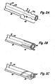
- FIGS. 2A-2E show perspective views of portions of catalytic reactor tubes 14 illustrating various fluid flow variation means. Illustrated in FIG. 2A is an embodiment of a reactor tube 14 containing a straight section 48 and a ribbed section 50.
- Straight section 48 is a section of standard round tubing containing a wall 50 which creates an internal flow path (such as 38 of FIG. 1).
- Ribbed section 52 contains an undulating profile which creates a series of ribs 54 containing maximum outer diameter D and minimum outer diameter d.
- Maximum outer diameter D is equal to or larger than the diameter of the straight section 48 of catalytic tube 14.
- minimum outer diameter d is equal to or less than the diameter of straight section 48 of catalytic tube 14.
- the ribs result in an expanding and contracting of the internal flow path, such as 38 of FIG. 1, of the tube which affects the flow of a fluid passing through the tube 14.
- Portions of either the interior or exterior of the tube 14 may contain catalyst 44 (FIG. 1).
- FIG. 2B Illustrated in FIG. 2B is an embodiment of a reactor tube 14 containing straight section 48 and fluted section 56.
- Straight section 48 is again a section of standard round tubing containing a wall 52 which creates an internal flow path such as 38 of FIG. 1.
- Fluted section 56 contains four internal ribs 58 to change the cross-sectional area of tube 14. In alternate embodiments, the number of internal ribs varies as required for design.
- the internal ribs 58 are illustrated as generally parallel to the central axis of tube 14, but in alternate embodiments, the ribs may be helically wound about the interior of tube 14.
- the catalyst 44 may be placed on the entire inner surface of tube 14, on only either the straight section or the fluted section, portions of both, or only on the ribs 58 or the internal surface excluding the ribs 58.
- FIG. 2C Illustrated in FIG. 2C is an embodiment of a reactor tube 14 containing straight section 48 and externally fluted section 60.
- Straight section 48 is again a section of standard round tubing containing a wall 52 which creates an internal flow path such as 38 of FIG. 1.
- Fluted section 60 contains three external flutes or channels 62 to change the cross-sectional area of tube 14. In alternate embodiments, the number of channels varies as required for design.
- the channels 62 are illustrated helically wound about central axis of tube 14, but may be generally parallel to the central axis in an alternate embodiment.
- the catalyst 44 may be placed on the entire exterior surface of tube 14, on only either the straight section 48 or the fluted section 60, portions of both, or only on channels 62 or exterior surface excluding channels 62.
- FIG. 2D Illustrated in FIG. 2D is an embodiment of a reactor tube 14 containing a straight section 48 and externally finned section 64.
- Straight section 48 is a section of standard round tubing containing a wall 52 which creates an internal flow path such as 38 of FIG. 1.
- Fins 66 are present on the outer surface of the tube 14. Fins 66 are illustrated as being perpendicular to the central axis of tube 14. In alternate embodiments, fins 66 are parallel to central axis, or helically spaced around tube 14. Fins 66 are of a constant height, but in alternate embodiments, fins 66 can be of varying heights. Fins 66 may also contain apertures to permit airflow through a portion of the fin (not illustrated).
- the catalyst 44 may be placed on the entire exterior surface of tube 14, on only either the straight section 48 or the finned section 64, portions of both, or only on fins 66 or the exterior surface of the tube excluding fins 66.
- FIG. 2E Illustrated in FIG. 2E is an embodiment of a reactor tube 14 containing a straight section 48 and a twisted section 68.
- Straight section 48 is a section of standard round tubing containing a wall 52 which creates an internal flow path (such as 38 of FIG. 1).
- Twisted section 68 contains an undulating profile from a dual twist of a portion of the tube: one twist clockwise and a second twist counterclockwise about the central axis of tube 14. The result is an expanding and contracting of wall 52 of tube 14 which affects the flow of a fluid passing either through the interior or adjacent the exterior of tube 14. Portions of either the interior or exterior of tube 14 may contain catalyst 44.
- FIGS. 3A-3C are cross-sectional views of reactor tube which also contain means for varying fluid flow. Illustrated in FIG. 3A is an embodiment of a reactor tube 14 containing longitudinally varying fins 66 of FIG. 2D. As illustrated, the fins 66 change in height along the length of the tube 14. Interior flow path 38 is uniform throughout the length of tube 14. Fluid flow passing adjacent tube 14 will be impeded by fins 66 which decrease is size. Catalyst 44 may be applied to fins 66. When this embodiment is used adjacent inlet aperture 22, the flow adjacent tube 14 is slowed upon entering the catalytic reactor for maximum heat transfer, and the rate of heat transfer is decreased as the fluid travels through tubel4. Fins 66 may be used alone, or in combination with the earlier described embodiments.
- FIG. 3B Illustrated in FIG. 3B is an embodiment of reactor tube 14 containing a change in pitch of twisted section 68.
- the embodiment is similar to those discussed in FIG. 1 and FIG. 2E, but twisted section 68 contains a nonuniform pitch per unit length.
- the increased pitch of the twists aid in impeding fluid flow, which changes the rate of transfer of heat through the tube as well as changing the velocity of fluids passing through and adjacent the exterior of tube 14.
- FIG. 3C Illustrated in FIG. 3C is an embodiment of reactor tube 14 containing a changing wall thickness. Wall thickness varies from minimum thickness t to maximum thickness T. As illustrated, tube 14 contains a uniform interior diameter. In an alternate embodiment, the exterior diameter remains constant and the interior diameter is decreased. Catalyst 44 can be applied to either the exterior or interior surface of tube 14.
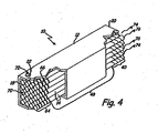
- FIG. 4 is a perspective view of a catalytic reactor 10 with a portion of the housing 12 removed.
- Catalytic reactor 10 is a structure comprised housing 12 and catalytic tubes 14.
- catalytic reactor 10 is generally constructed to contain a square-packed arrangement of parallel, equal-length, cylindrically-shaped catalytic tubes 14 within housing 12. Tubes 14 comprise twisted portions 40 adjacent exit 20, straight portion 48, and finned portions 64 adjacent entrance 18.
- Tubes 14 comprise twisted portions 40 adjacent exit 20, straight portion 48, and finned portions 64 adjacent entrance 18.
- other geometries for housing 12 are envisioned including cylindrical, polygonal prisms, toroidal, L-shaped, conical geometries or combinations thereof.
- catalytic tubes may be of any of the embodiments disclosed herein and need not comprise a straight 48 or finned entrance section as depicted in embodiments detailed herein.
- the impact of swirl to enhance mixing can be simulated at the exit of the reactor by creating fluid dynamic strain where the two exit streams mix.
- the reacting flow in the tube and corresponding cooling air flow stream may exit with the same flow orientation (e.g. swirl) about a given tube.
- the reacted fuel/air mixture may exit straight through the exit while the cooling air flow on either side of the fuel/air passage alternate direction.
- the opposite configuration may be used also.
- a first fluid of fuel/air mixture enters the catalytic tubes 14 at or near entrance 18 as represented by arrow 70.
- a second fluid comprising ambient air is introduced into the flow paths between adjacent catalytic tubes 14 through inlet aperture 22 as represented by arrow 72.
- the second fluid is similar in composition to the first fluid and contains a fuel/air mixture.
- the interior surface of catalytic tubes 14 contain a catalyst which reacts with the first fluid and generates heat. The second fluid acts a cooling fluid and absorbs the heat generated by the reaction.
- the flow 72 adjacent the exterior of tubes 14 is slowed upon entering the catalytic reactor by the presence of fins 66 of finned section 64.
- the fins 66 thus act to adjust the rate of heat transfer near the entrance by keeping the second fluid 72 in contact with the first portion of the reactor tube 14. This results in a more uniform temperature gradient through the catalytic reactor 10, thus extending its useful life.
- the fluids 70, 72 leave the catalytic reactor 10 at exit 20. Due to the presence of the twisted portion 40 of catalytic tubes 14, the first fluid exits tubes 14 in an agitated flow pattern as represented by arrows 74. The second fluid is also leaving exit 20 as turbulent flow also as represented by arrows 76. The fluids 74, 76 mix upon leaving exit 20. The agitation of fluid flow created by the twisted portion 40 aids in the mixing of the first and second fluids at exit 20 to create a single heated, and partially reacted, third fluid for combustion.
- catalytic tubes 14, including twisted portions 40 are cylindrical and concentric with a respective conduit centerline.
- other cross-sectional geometries of the catalytic tubes 14 are envisioned, including ellipses, polygons, or combinations thereof for both the main portion and twisted portion 40 of the catalytic tubes 14.
- Figs. 5A and 5B show differing embodiments of catalytic reactors 10A and 10B.
- Fig. 5A depicts a cross-sectional view of a portion of turbine engine 78A with catalytic reactor 10A and combustion chamber 80A.
- catalytic reactor is a trapezoid in cross section.
- Catalytic reactor 10A contains housing12A, which may be a trapezoidal prism or frustum.
- Reactor 10A contains catalytic tubes (not illustrated), and decreases in cross-sectional area near 20A. This configuration of the reactor housing 12A aids in modifying fluid flow near the exit to promote a desired mixing as the fluid leaves reactor 10A and enters combust chamber 80A.
- the catalytic tubes contain any of the disclosed means for varying a property of the fluid passing therein or adjacent thereto.
- Fig. 5B depicts a cross-sectional view of a portion of turbine engine 78B with catalytic reactor 10B and combustion chamber 80B.
- catalytic reactor 10B is rectangular in cross section, and contains housing 12B, which may form a polygonal prism or cylinder.
- catalytic reactor 10B contains catalytic tubes (not illustrated). The tubes contain any of the disclosed means for varying a property of the fluid passing therein or adjacent thereto, which aids in the mixing of the fluid leaving exit 14B of catalytic reactor 10B.
- a catalytic reactor of any of the disclosed embodiments is designed for maximum catalytic reaction in normal operating conditions, while minimizing variations in chemical reaction rates and mass transfer rates due to fluid flow fluctuations.
- Catalysts are applied in coatings on a weight basis in relationship to geometric surface area of catalyst. Insufficient coating area will result in an insufficient catalytic reaction for the desired reactor and combustor design due to insufficient total mass transfer from the fluid to the catalytic surface.
- the required coating area depends upon operating conditions (e.g. reactant temperature, pressure, velocity, composition) and catalyst activity, and can be determined by methods known in chemical engineering practice.
- fluid flow will be slowed, adjusted, or disturbed in a controlled fashion, thus allowing for greater residence time with the coating area containing the catalyst. This produces a decrease of the required surface area of the catalyst, which results in smaller and less expensive reactors.
- design of a reactor will balance the surface area for reaction and cooling with the desired volumetric flow rates of the relevant fluids passing through the reactor.
- the change in fluid flow is desirable for promoting the mixing of fluids on the reacting (catalyst coated) side and cooling side.
- the enhanced mixing of fluids will shorten the required mixing length prior to the main combustor, and also shorten the mixing time, which are important in some applications to prevent premature ignition. Premature ignition in the post-reactor mixing zone will result in excess NOx production and increased chance of hardware failure.
- the catalytic reactor of the current invention is used for combusting a catalyzed hydrocarbon fuel.
- a first fluid is passed into catalytic tubes of the catalytic reactor, while a second fluid is passed adjacent the catalytic tubes in the flow paths of the chamber of the catalytic reactor.
- Both the first fluid and the second fluid can be comprised of air/fuel mixture, or an air stream.
- At least one of the fluids is comprised of air/fuel mixture and is in contact with a catalyst.
- the other fluid can be comprised of air/fuel mixture or a different gas or gas mixture such as air.
- the fluid variation means is provided for at least a portion of the tube to modify the flow of the first fluid, and/or add to the catalytic reaction.
- the flow of the first fluid leaving the catalytic tubes is mixed with the second fluid, and this mixture is combusted.
- the heat of the catalytic reaction is extracted from fluid in contact with the catalyst and transferred to the other fluid.
- the second fluid is controllably introduced into the catalytic reactor.
- a third fluid such as additional air or additional air/fuel mixture, can be added to the mixture of the first fluid and the second fluid upon exiting the reactor to achieve a desired equivalence ratio for combustion.
- the catalytic reactor may be designed so that the catalyst is only present on a portion of the catalytic tube.
- a reactor may be designed containing any length and geometry of catalytic tube covered with any length with catalyst, and containing a fluid variation means along any portion the catalytic tube.
- the catalytic tube may contain catalyst in the last two-thirds of the catalytic tube, or its first two-thirds, while a fluid variation means is placed within the tube that has an effective length of the last one-third of the tube.
- the fluid variation means slows the flow of a fluid in the catalytic tube for the last portion of the tube, and creates a turbulence which allows for better mixing upon exiting of the tube.
- the catalytic tubes containing the fluid variation means enables reduction of the wall temperature at the entrance by modifying the geometry near the front of the reactor.
- the variations in the tube increase the available surface area for heat transfer and/or decrease the initial fluid velocity of the reacting side to reduce temperatures in the system.
- the tube is designed to contain a geometric design that promotes higher velocities on the reacting side with lower surface areas on the cooling air side to maintain reactivity and minimize pressure loss.
- the transition may be approximately 20% from the entrance or the exit of the reactor, but may occur anywhere from 5% to 90% along the length depending on the geometric features utilized.
- Placing fluid variation means into a portion of the catalytic tubes of the catalytic reactor results in increased surface area per unit length for oxidizing the fuel/air mixture internal to the conduits where the catalyst is applied.
- the result is a tortuous flow path internal to the conduits or adjacent the tube exterior, which produces swirl within the conduits or housing to increase residence time for oxidizing the fuel/air mixture.
- the shape of a conduit can be designed to promote swirl and shear mixing at the exit of the catalytic tube or conduit.
- the fluid variation means can be at another portion of the tube, such as near the entrance or central portion to provide turbulence in the fluid flow to increase reaction time within the reactor and create a more uniform temperature gradient along the tube length.
- the embodiments disclosed herein can be utilized to design a catalytic reactor with tubes designed to optimize the velocity, heat transfer, and mixing of the fluids to obtain a reactor of a specified size and geometry.
Landscapes
- Chemical & Material Sciences (AREA)
- Chemical Kinetics & Catalysis (AREA)
- Engineering & Computer Science (AREA)
- Organic Chemistry (AREA)
- Combustion & Propulsion (AREA)
- General Engineering & Computer Science (AREA)
- Mechanical Engineering (AREA)
- Health & Medical Sciences (AREA)
- Biomedical Technology (AREA)
- Environmental & Geological Engineering (AREA)
- Analytical Chemistry (AREA)
- General Chemical & Material Sciences (AREA)
- Oil, Petroleum & Natural Gas (AREA)
- Physical Or Chemical Processes And Apparatus (AREA)
Abstract
Description
- The present invention is directed to a system and method for combusting hydrocarbon fuels in an efficient manner which minimizes pollutant emissions, particularly NOx emissions.
- Exhaust gases produced in the combustion of hydrocarbon fuels by engines contribute to atmospheric pollution. Exhaust gases typically contain nitric oxide (NO), nitrogen dioxide (NO2), carbon monoxide, and unburned hydrocarbons. Nitrogen oxides are a cause of smog, acid rain, and depletion of stratospheric ozone. With high combustion temperatures in an engine, oxygen and nitrogen combine to form the pollutants NO and NO2 (collectively known as "NOx"). Typical fuels reacting with air exceed the threshold temperature which results in NOx formation.
- A reduction in the formation of NOx is desirable. One method to control NOx is to employ a catalyst that allows low-temperature reaction of fuel and air. Most, if not all, of the fuel can be reacted at a moderate temperature, thus inhibiting formation of NOx. The use of a catalyst results in a pre-reaction of a portion of a fuel to stabilize the main combustion process. The catalytic process is referred to as catalytic combustion.
- When reacting fuel with a catalyst, heat is generated. This heat must be controlled to result in a lower combustion temperature. Typically only a portion of the total fuel to be burned is reacted in the catalyst chamber. One solution to the problem of heat production is to provide a stream of cooling air about a stream of fluid that is in contact with the catalyst or a substrate to which the catalyst is attached or resides. Such a process uses heat exchange in which certain channels contain the catalyzed fluid, while other channels contain air for cooling and absorbing heat from the catalytic reaction. These two fluid streams can then be mixed upon exiting the heat exchanger and combusted with a reduction of NOx.
- In catalytic combustors (or catalytic reactors), hydrocarbon fuel is mixed with a first air stream to form a fuel and air mixture having an equivalence ratio greater than unity, that is with fuel in excess, and partially oxidized by contacting the fuel/air fluid mixture with an oxidation catalyst stage, thereby generating the heat of reaction in a partial oxidation product stream comprising hydrogen, water, and carbon oxides. The reaction is intended to be pure catalytic, thus minimizing the formation of oxides of nitrogen (NOx).
- A portion of the heat of reaction is conducted through the wall of a substrate on which the catalyst resides and is removed via the back side convection and conduction heat transfer to the second air stream and/or compatible cooling fluid. The partial oxidation product stream is mixed with a second air stream, which is raised in temperature from its initial state via the heat of reaction, and subsequently combusted in a down stream combustor. The down stream combustor can include additional fuel or air mixtures that contribute to combustion in single or multiple zones.
- The fuel/air mixture flows into a catalytic oxidation stage and contacts an oxidation catalyst which partially oxidizes the mixture to generate heat and a partial oxidation product stream comprising hydrogen, carbon oxides (primarily CO), and unreacted hydrocarbon fuel. Catalytic oxidation in this context is intended to drive a rapid oxidation or oxidative pyrolysis reaction carried out at a temperature below that required to support thermal combustion or combustion without a flame at a temperature below which thermal NOx will not form in appreciable amounts. Partial oxidation means that there is insufficient oxygen available to completely convert fuel to carbon dioxide and water, and thus fully liberate the chemical energy stored in the fuel. Since complete oxidation improves the energy potential of the fuel, any improvement in the catalytic reactor is beneficial.
- A practical problem in the design of an integrated catalytic reactor - heat exchanger is balancing the rate of reaction and chemical heat release with the rate of heat exchanged to the adjacent cooling flow. If not well-balanced, sections of the reactor can over heat leading to premature failures or loss of activity. Such a situation often occurs at the leading edge of a reactor system. Reaction rates could be changed by altering the catalyst loading on the catalytic surface. Such a strategy is generally not acceptable, however, since system performance will be adversely affected as the catalyst degrades. It is better to design the hardware such that the rate limiting processes are based on geometry and fluid flow conditions, and hence controlled by transport processes rather than catalytic activity. This invention provides such a strategy.
- The current invention seeks to improve current catalytic reactor designs. In a disclosed embodiment of the invention, a change in the cross-sectional area and shape of a catalytic tube or channel promotes turbulence in fluid flow passing through and around the catalytic tube. Altered turbulence levels will change the rate of heat and mass transfer and hence the effectiveness of the catalytic conversion and/or the rate of of energy exchange between the adjacent passages. By varying the area/shape along the length of the reactor the design can be tailored or optimized depending on whether the catalytic reaction or the heat exchange is to be locally enhanced or suppressed as defined by performance criteria. The cross-sectional design is used in a catalytic reactor to allow for a method of improved combustion of a catalyzed fuel by either adding to the catalyst surface area, or changing the residence time of a fluid with the catalyst, or both, and promoting mixture and swirl of the catalyzed fluid with another fluid.
-
- FIG. 1 depicts a longitudinal cross-section of a first embodiment of a catalytic reactor containing an insert within a catalyst tube.
- FIG. 2A shows a perspective view of a reactor tube containing a ribbed section.
- FIG. 2B is a perspective view of a reactor tube containing an internally fluted section.
- FIG. 2C illustrates a perspective view of a reactor tube containing an externally fluted section.
- FIG. 2D is a perspective view of a reactor tube containing an externally finned section.
- FIG. 2E is a perspective view of a reactor tube containing a twisted section.
- FIG. 3A is a cross-sectional view of a reactor tube containing a gradient of external fins.
- FIG. 3B is a cross-sectional view of a reactor tube containing a change in twist pitch.
- FIG. 3C is a cross-sectional view of a reactor tube containing a changing wall thickness.
- FIG. 4 is a perspective view of a catalytic reactor with a portion of the housing removed.
- FIG 5A is a cross-sectional view of a turbine engine containing a catalytic reactor and combustion chamber.
- FIG 5B is a cross-sectional view of a second turbine engine containing a catalytic reactor and combustion chamber.
- FIG. 1 depicts a longitudinal cross-section of
catalytic reactor 10, which includes housing 12 andcatalyst tubes 14.Catalytic reactor 10 may be integrated with a gas turbine combustion system (not illustrated). In this embodiment, housing 12 contains anentrance 18 and anexit 20. Housing 12 contains at least one aperture 22 for introducing an additional fluid into housing 12. A wall 24 of housing 12 andexterior surface 36 ofcatalyst tubes 14 create afluid flow path 28 from theentrance 18 or aperture 22 to theexit 20.Entrance 18 comprises agrate 30 connected to wall 24 of housing 12. Grate 24 securescatalyst tubes 14 in place within the housing 12, while allowing for the introduction of fluids intocatalyst tubes 14 and flowpath 28.Grate 30 and wall 24 of housing 12 are constructed from metal or other material system suited for the application.Exit 20 allows fluids flowing withinflow path 28 to exit the housing 12. -
Catalyst tubes 14 are made from a heat conducting material and adapted for conducting fluid flow internally and within the housing 12.Catalyst tubes 14 have atube entrance 26, atube exit 32, an interior surface 34, and anexterior surface 36. The interior surface 34 creates aninterior flow path 38 within thecatalyst tube 14. Aportion 40 ofcatalyst tube 14 adjacent thetube exit 32 contains a differing cross section to change the flow direction and velocity of the fluid exiting thecatalyst tube 14. -
Flow paths 28 within housing 12 are defined by the tube exterior surfaces 36 and wall 24.Flow paths 28 are in communication with aperture 22 andexit 20.Flow paths 28 can have varying configurations dependent upon the shape and spacing ofcatalyst tubes 14 and wall 24 of housing 12.Flow paths 28 permit the flow and diffusion of a fluid in a manner to allow heat transfer with the fluids flowing withincatalyst tubes 14. In one embodiment,flow paths 28 extend between the inlet aperture 22 and flowpath exit 42, and prevent the fluid flowing there from contacting the fluid in thecatalytic tubes 14. Flow path exit 42 is a grate similar to thegrate 30 ofentrance 18, although a variety of other entrance and exit designs are acceptable. - The result of a varied section of the tube is to produce swirl to increase turbulence and residence time as well as catalytic surface area per unit length within the catalyst tube, which results in more oxidation of a fluid comprised of fuel and air. Thus, the catalytic reaction per unit of length of
catalyst tube 14 is increased. Also, the production of swirl results in a turbulated flow as the fluid exits the tubes. This aids in mixing the fluid exiting the tubes with a fluid exiting theflowpaths 28 of thereactor 10 atexit 20, a fluid being introduced adjacent theexit 20, or both. - A catalyst 44 is deposited on a portion of the
catalytic tube 14. In one embodiment, catalyst 44 can be deposited anywhere in theflow path 38 throughtube 14. A fuel-rich fuel/air mixture is mixed prior to delivery tointerior flow path 38 created bycatalytic tube 14. Alternately, mixing of fuel and air withinflow path 38 is possible due to the turbulence of fluid flow created by non-periodic varied portion oftube 14. In an alternate embodiment, the catalyst 44 is deposited on theexterior surface 36 ofcatalytic tube 14, or on portions of both theinterior flow path 38 andexterior surface 36. - When the fuel is a hydrocarbon or hydrocarbon oxygenate, and the oxidizer is oxygen or air or a combination thereof, catalyst 44 may include group VIII noble metals, base metals, metal oxides, or a combination thereof. Elements including zirconium, vanadium, chromium, manganese, copper, platinum, palladium, ruthenium, osmium, iridium, rhodium, cerium, lanthanum, other elements of the lanthanide series, cobalt, nickel, and iron are all suitable, as well as chromium oxides, cobalt oxides, and alumina, or mixtures thereof. Catalyst 44 is applied directly to the substrate, or in an alternate embodiment, is applied to a bonding coat or washcoat composed of such materials as alumina, silica, zirconia, titania, magnesia, yttrium, other refractory metal oxides, or a combination thereof.
- The substrate comprising the
catalytic tubes 14 is fabricated from high-temperature materials. In one embodiment, high temperature nickel alloy is used. In alternate embodiments, high-temperature metal alloys are used, including alloys composed of iron, nickel, and/or cobalt, in combination with aluminum, chromium, and/or other alloying materials. Other substrate materials include ceramics, metal oxides, intermetallic materials, carbides, and nitrides. Metallic substrates and refractories are most preferred due to their excellent thermal conductivity, allowing effective backside cooling of the catalyst. - In the embodiment of FIG. 1, a portion of interior surface 34 of
catalytic tube 14 is coated with catalyst 44. In this embodiment, a first fluid comprising fuel/air mixture is introduced intocatalytic tubes 14 at entrances 26. A second fluid, either air or additional fuel/air mixture, is introduced intocatalytic reactor 10 at aperture 22, the second fluid absorbing the heat of the catalytic reaction to lower the temperature of the first fluid. The change in the crosssectional area 40 oftube 14 not only increases the residence time of the first fluid, but also acts to further the reaction of the first fluid. - FIGS. 2A-2E show perspective views of portions of
catalytic reactor tubes 14 illustrating various fluid flow variation means. Illustrated in FIG. 2A is an embodiment of areactor tube 14 containing astraight section 48 and a ribbed section 50.Straight section 48 is a section of standard round tubing containing a wall 50 which creates an internal flow path (such as 38 of FIG. 1).Ribbed section 52 contains an undulating profile which creates a series ofribs 54 containing maximum outer diameter D and minimum outer diameter d. Maximum outer diameter D is equal to or larger than the diameter of thestraight section 48 ofcatalytic tube 14. Similarly, minimum outer diameter d is equal to or less than the diameter ofstraight section 48 ofcatalytic tube 14. The ribs result in an expanding and contracting of the internal flow path, such as 38 of FIG. 1, of the tube which affects the flow of a fluid passing through thetube 14. Portions of either the interior or exterior of thetube 14 may contain catalyst 44 (FIG. 1). - Illustrated in FIG. 2B is an embodiment of a
reactor tube 14 containingstraight section 48 andfluted section 56.Straight section 48 is again a section of standard round tubing containing awall 52 which creates an internal flow path such as 38 of FIG. 1.Fluted section 56 contains four internal ribs 58 to change the cross-sectional area oftube 14. In alternate embodiments, the number of internal ribs varies as required for design. The internal ribs 58 are illustrated as generally parallel to the central axis oftube 14, but in alternate embodiments, the ribs may be helically wound about the interior oftube 14. In an embodiment where catalyst 44 is present on the interior oftube 14, the catalyst 44 may be placed on the entire inner surface oftube 14, on only either the straight section or the fluted section, portions of both, or only on the ribs 58 or the internal surface excluding the ribs 58. - Illustrated in FIG. 2C is an embodiment of a
reactor tube 14 containingstraight section 48 and externally flutedsection 60.Straight section 48 is again a section of standard round tubing containing awall 52 which creates an internal flow path such as 38 of FIG. 1.Fluted section 60 contains three external flutes or channels 62 to change the cross-sectional area oftube 14. In alternate embodiments, the number of channels varies as required for design. The channels 62 are illustrated helically wound about central axis oftube 14, but may be generally parallel to the central axis in an alternate embodiment. In an embodiment where catalyst 44 is present on the exterior oftube 14, the catalyst 44 may be placed on the entire exterior surface oftube 14, on only either thestraight section 48 or thefluted section 60, portions of both, or only on channels 62 or exterior surface excluding channels 62. - Illustrated in FIG. 2D is an embodiment of a
reactor tube 14 containing astraight section 48 and externally finnedsection 64.Straight section 48 is a section of standard round tubing containing awall 52 which creates an internal flow path such as 38 of FIG. 1. Fins 66 are present on the outer surface of thetube 14. Fins 66 are illustrated as being perpendicular to the central axis oftube 14. In alternate embodiments, fins 66 are parallel to central axis, or helically spaced aroundtube 14. Fins 66 are of a constant height, but in alternate embodiments, fins 66 can be of varying heights. Fins 66 may also contain apertures to permit airflow through a portion of the fin (not illustrated). In an embodiment where catalyst 44 is present on the exterior oftube 14, the catalyst 44 may be placed on the entire exterior surface oftube 14, on only either thestraight section 48 or thefinned section 64, portions of both, or only on fins 66 or the exterior surface of the tube excluding fins 66. - Illustrated in FIG. 2E is an embodiment of a
reactor tube 14 containing astraight section 48 and atwisted section 68.Straight section 48 is a section of standard round tubing containing awall 52 which creates an internal flow path (such as 38 of FIG. 1).Twisted section 68 contains an undulating profile from a dual twist of a portion of the tube: one twist clockwise and a second twist counterclockwise about the central axis oftube 14. The result is an expanding and contracting ofwall 52 oftube 14 which affects the flow of a fluid passing either through the interior or adjacent the exterior oftube 14. Portions of either the interior or exterior oftube 14 may contain catalyst 44. - FIGS. 3A-3C are cross-sectional views of reactor tube which also contain means for varying fluid flow. Illustrated in FIG. 3A is an embodiment of a
reactor tube 14 containing longitudinally varying fins 66 of FIG. 2D. As illustrated, the fins 66 change in height along the length of thetube 14.Interior flow path 38 is uniform throughout the length oftube 14. Fluid flow passingadjacent tube 14 will be impeded by fins 66 which decrease is size. Catalyst 44 may be applied to fins 66. When this embodiment is used adjacent inlet aperture 22, the flowadjacent tube 14 is slowed upon entering the catalytic reactor for maximum heat transfer, and the rate of heat transfer is decreased as the fluid travels through tubel4. Fins 66 may be used alone, or in combination with the earlier described embodiments. - Illustrated in FIG. 3B is an embodiment of
reactor tube 14 containing a change in pitch oftwisted section 68. The embodiment is similar to those discussed in FIG. 1 and FIG. 2E, buttwisted section 68 contains a nonuniform pitch per unit length. The increased pitch of the twists aid in impeding fluid flow, which changes the rate of transfer of heat through the tube as well as changing the velocity of fluids passing through and adjacent the exterior oftube 14. - Illustrated in FIG. 3C is an embodiment of
reactor tube 14 containing a changing wall thickness. Wall thickness varies from minimum thickness t to maximum thickness T. As illustrated,tube 14 contains a uniform interior diameter. In an alternate embodiment, the exterior diameter remains constant and the interior diameter is decreased. Catalyst 44 can be applied to either the exterior or interior surface oftube 14. - FIG. 4 is a perspective view of a
catalytic reactor 10 with a portion of the housing 12 removed.Catalytic reactor 10 is a structure comprised housing 12 andcatalytic tubes 14. In the embodiment shown in FIG. 4,catalytic reactor 10 is generally constructed to contain a square-packed arrangement of parallel, equal-length, cylindrically-shapedcatalytic tubes 14 within housing 12.Tubes 14 comprise twistedportions 40adjacent exit 20,straight portion 48, and finnedportions 64adjacent entrance 18. Although illustrated as a parallelopiped, other geometries for housing 12 are envisioned including cylindrical, polygonal prisms, toroidal, L-shaped, conical geometries or combinations thereof. Moreover, catalytic tubes may be of any of the embodiments disclosed herein and need not comprise a straight 48 or finned entrance section as depicted in embodiments detailed herein. - The impact of swirl to enhance mixing can be simulated at the exit of the reactor by creating fluid dynamic strain where the two exit streams mix. The reacting flow in the tube and corresponding cooling air flow stream may exit with the same flow orientation (e.g. swirl) about a given tube. Alternatively, the reacted fuel/air mixture may exit straight through the exit while the cooling air flow on either side of the fuel/air passage alternate direction. The opposite configuration may be used also.
- Referring to Fig. 4, a first fluid of fuel/air mixture enters the
catalytic tubes 14 at or nearentrance 18 as represented byarrow 70. Simultaneously, a second fluid comprising ambient air is introduced into the flow paths between adjacentcatalytic tubes 14 through inlet aperture 22 as represented byarrow 72. Although only a single inlet aperture 22 is visible in Fig. 4, it is envisioned that there may be a plurality of inlet apertures locatedadjacent entrance 18. In an alternate embodiment, the second fluid is similar in composition to the first fluid and contains a fuel/air mixture. The interior surface ofcatalytic tubes 14 contain a catalyst which reacts with the first fluid and generates heat. The second fluid acts a cooling fluid and absorbs the heat generated by the reaction. Theflow 72 adjacent the exterior oftubes 14 is slowed upon entering the catalytic reactor by the presence of fins 66 of finnedsection 64. The fins 66 thus act to adjust the rate of heat transfer near the entrance by keeping thesecond fluid 72 in contact with the first portion of thereactor tube 14. This results in a more uniform temperature gradient through thecatalytic reactor 10, thus extending its useful life. - The
fluids catalytic reactor 10 atexit 20. Due to the presence of the twistedportion 40 ofcatalytic tubes 14, the first fluid exitstubes 14 in an agitated flow pattern as represented byarrows 74. The second fluid is also leavingexit 20 as turbulent flow also as represented byarrows 76. Thefluids exit 20. The agitation of fluid flow created by the twistedportion 40 aids in the mixing of the first and second fluids atexit 20 to create a single heated, and partially reacted, third fluid for combustion. - In the embodiment illustrated FIG. 4,
catalytic tubes 14, includingtwisted portions 40, are cylindrical and concentric with a respective conduit centerline. In alternate embodiments, other cross-sectional geometries of thecatalytic tubes 14 are envisioned, including ellipses, polygons, or combinations thereof for both the main portion andtwisted portion 40 of thecatalytic tubes 14. - Figs. 5A and 5B show differing embodiments of
catalytic reactors 10A and 10B. Fig. 5A depicts a cross-sectional view of a portion ofturbine engine 78A with catalytic reactor 10A and combustion chamber 80A. In this embodiment, catalytic reactor is a trapezoid in cross section. Catalytic reactor 10A contains housing12A, which may be a trapezoidal prism or frustum. Reactor 10A contains catalytic tubes (not illustrated), and decreases in cross-sectional area near 20A. This configuration of thereactor housing 12A aids in modifying fluid flow near the exit to promote a desired mixing as the fluid leaves reactor 10A and enters combust chamber 80A. Additionally, the catalytic tubes contain any of the disclosed means for varying a property of the fluid passing therein or adjacent thereto. - Fig. 5B depicts a cross-sectional view of a portion of turbine engine 78B with
catalytic reactor 10B and combustion chamber 80B. In this embodiment,catalytic reactor 10B is rectangular in cross section, and contains housing 12B, which may form a polygonal prism or cylinder. In this embodiment,catalytic reactor 10B contains catalytic tubes (not illustrated). The tubes contain any of the disclosed means for varying a property of the fluid passing therein or adjacent thereto, which aids in the mixing of the fluid leaving exit 14B ofcatalytic reactor 10B. - A catalytic reactor of any of the disclosed embodiments is designed for maximum catalytic reaction in normal operating conditions, while minimizing variations in chemical reaction rates and mass transfer rates due to fluid flow fluctuations. Catalysts are applied in coatings on a weight basis in relationship to geometric surface area of catalyst. Insufficient coating area will result in an insufficient catalytic reaction for the desired reactor and combustor design due to insufficient total mass transfer from the fluid to the catalytic surface. The required coating area depends upon operating conditions (e.g. reactant temperature, pressure, velocity, composition) and catalyst activity, and can be determined by methods known in chemical engineering practice.
- With the presence of the fluid variation means of the catalytic tubes of a catalytic reactor, fluid flow will be slowed, adjusted, or disturbed in a controlled fashion, thus allowing for greater residence time with the coating area containing the catalyst. This produces a decrease of the required surface area of the catalyst, which results in smaller and less expensive reactors. Thus, design of a reactor will balance the surface area for reaction and cooling with the desired volumetric flow rates of the relevant fluids passing through the reactor. Also, the change in fluid flow is desirable for promoting the mixing of fluids on the reacting (catalyst coated) side and cooling side. The enhanced mixing of fluids will shorten the required mixing length prior to the main combustor, and also shorten the mixing time, which are important in some applications to prevent premature ignition. Premature ignition in the post-reactor mixing zone will result in excess NOx production and increased chance of hardware failure.
- The catalytic reactor of the current invention is used for combusting a catalyzed hydrocarbon fuel. A first fluid is passed into catalytic tubes of the catalytic reactor, while a second fluid is passed adjacent the catalytic tubes in the flow paths of the chamber of the catalytic reactor. Both the first fluid and the second fluid can be comprised of air/fuel mixture, or an air stream. At least one of the fluids is comprised of air/fuel mixture and is in contact with a catalyst. The other fluid can be comprised of air/fuel mixture or a different gas or gas mixture such as air. The fluid variation means is provided for at least a portion of the tube to modify the flow of the first fluid, and/or add to the catalytic reaction. The flow of the first fluid leaving the catalytic tubes is mixed with the second fluid, and this mixture is combusted. The heat of the catalytic reaction is extracted from fluid in contact with the catalyst and transferred to the other fluid. In one embodiment, the second fluid is controllably introduced into the catalytic reactor. A third fluid, such as additional air or additional air/fuel mixture, can be added to the mixture of the first fluid and the second fluid upon exiting the reactor to achieve a desired equivalence ratio for combustion.
- Although illustrated in FIG. 1 as containing a catalyst on the substantial portion of
catalytic tube 14, the catalytic reactor may be designed so that the catalyst is only present on a portion of the catalytic tube. Thus, it is envisioned that a reactor may be designed containing any length and geometry of catalytic tube covered with any length with catalyst, and containing a fluid variation means along any portion the catalytic tube. For example, the catalytic tube may contain catalyst in the last two-thirds of the catalytic tube, or its first two-thirds, while a fluid variation means is placed within the tube that has an effective length of the last one-third of the tube. The fluid variation means slows the flow of a fluid in the catalytic tube for the last portion of the tube, and creates a turbulence which allows for better mixing upon exiting of the tube. - Application of the catalytic tubes containing the fluid variation means enables reduction of the wall temperature at the entrance by modifying the geometry near the front of the reactor. The variations in the tube increase the available surface area for heat transfer and/or decrease the initial fluid velocity of the reacting side to reduce temperatures in the system. However, it is not preferable to maintain the variation means throughout the catalytic tube length as the variation in geometry will result in a prohibitive pressure drop in the fluid flow. In one embodiment, the tube is designed to contain a geometric design that promotes higher velocities on the reacting side with lower surface areas on the cooling air side to maintain reactivity and minimize pressure loss. For example, the transition may be approximately 20% from the entrance or the exit of the reactor, but may occur anywhere from 5% to 90% along the length depending on the geometric features utilized.
- Placing fluid variation means into a portion of the catalytic tubes of the catalytic reactor results in increased surface area per unit length for oxidizing the fuel/air mixture internal to the conduits where the catalyst is applied. The result is a tortuous flow path internal to the conduits or adjacent the tube exterior, which produces swirl within the conduits or housing to increase residence time for oxidizing the fuel/air mixture. The shape of a conduit can be designed to promote swirl and shear mixing at the exit of the catalytic tube or conduit. Alternately, the fluid variation means can be at another portion of the tube, such as near the entrance or central portion to provide turbulence in the fluid flow to increase reaction time within the reactor and create a more uniform temperature gradient along the tube length. Overall, the embodiments disclosed herein can be utilized to design a catalytic reactor with tubes designed to optimize the velocity, heat transfer, and mixing of the fluids to obtain a reactor of a specified size and geometry.
- With the turbulated flow pattern, the product stream and secondary air streams mix rapidly upon leaving the catalytic reactor and effectively combine to allow combustion of fuel mixture. This reduces emissions from levels currently present in the state of the art, and the potential to remove the size of this secondary region for combustion and the required complexity therein. Overall, adding fluid variation means which increase residence time, i.e. the time the fluid is in the catalytic tube, resulting in greater reaction per unit length. This will allow for the reduction of the size of equipment and the complexity of combustor assemblies.
- Although the present invention has been described with reference to preferred embodiments, workers skilled in the art will recognize that changes may be made in form and detail without departing from the scope of the invention.
Claims (23)
- A catalyst conduit for a catalytic reactor (10) of a turbine combustor, the conduit comprising:a tube (14) including an inlet (26) and an outlet (32), and a wall with an interior surface (34) and an exterior surface (36), wherein the tube (14) contains a variation in its cross sectional area along at least a portion of its length to change a property of a fluid flowing adjacent the wall of the tube (14); andan oxidation catalyst (44) deposited on at least a portion of the tube(14).
- The conduit of claim 1 wherein the variation in the cross sectional area of the tube (14) changes velocity of the fluid in the tube to promote turbulence in the fluid upon exiting the tube.
- The conduit of claim 1 wherein a non-periodic variation in the cross sectional area of the tube (14) impedes the flow of the fluid on either side of the tube wall allowing for greater heat transfer through the tube wall.
- The conduit of claim 1 wherein the variation in the cross sectional area of the tube (14) is a series of ribs (54) creating an undulating profile of the tube wall.
- The conduit of claim 1 wherein the tube wall (52) is helically fluted, and wherein the variation in the cross sectional area of the tube (14) is a change in pitch of helical flutes comprising the tube wall.
- The conduit of claim 5 wherein the variation in the cross sectional area of the tube (14) is a change of the tube wall thickness with respect to a central axis of the tube.
- The conduit of claim 1 further wherein the variation in cross sectional area of the tube (14) is a series of fins (66).
- The conduit of claim 1 further wherein the variation in cross sectional area of the tube (14) is a twisted portion (68) of the tube (14) to create an undulating profile.
- The conduit of claim 8 wherein the twisted portion (68) contains a non-uniform pitch of the twists per unit length.
- The conduit of claim 8 or 9 wherein the twisted portion (68) contains dual twists, one twist clockwise about a central axis of the tube (14), and one twist counterclockwise about the central axis of the tube (14).
- The conduit of any preceding claim wherein the variation of the cross sectional area of the tube (14) is present approximately at the last one-third of the tube (14).
- A catalytic reactor (10) comprising:a housing (12) having an inlet (18) and an outlet (20), the housing (12) defining an interior chamber;a plurality of tubes (14) mounted within the interior chamber of the housing, each tube (14) comprising:wherein an interior of the tubes (14) form a first fluid pathway; and the exterior surfaces of the tubes and the interior chamber form a second fluid pathway containing an exit port; andan inlet (26) and an outlet (32), and a wall with an interior surface (34) and an exterior surface (36), wherein the tubes (14) contain means for varying a property of a fluid passing adjacent the wall of the tube; andan oxidation catalyst (44) deposited on at least a portion of the tube (14);
wherein the outlets (32) of the plurality of tubes (14) and the exit port are proximately located such that a first fluid exiting the outlets (32) of the plurality of tubes (14) mixes with a second fluid exiting the housing through the exit port. - The catalytic reactor of claim 12 wherein the means for varying comprises a change in cross sectional area of the tube (14) from a change in the tube wall thickness.
- The catalytic reactor of claim 12 wherein the means for varying comprises a tube wall (52) that is helically fluted.
- The catalytic reactor of claim 12 further comprising:a series of fins (16) attached to the exterior surface (36) of the tube wall, wherein the means for varying the fluid property is a change in the gradient of the series of fins.
- The catalytic reactor of any of claims 12 to 15 wherein the means for varying is present for less than one-half the total length of the tube.
- The catalytic reactor of any of claims 12 to 16 wherein the oxidation catalyst (44) is deposited on the exterior surfaces (36) of the plurality of tubes (14).
- The catalytic reactor of any of claims 12 to 17 wherein the oxidation catalyst (44) is deposited on the interior surfaces (34) of the plurality of tubes (14).
- A method of combusting a catalyzed hydrocarbon fuel, the method comprising:providing a first fluid and a second fluid, at least one of said fluids comprising a mixture of a hydrocarbon fuel with an air stream;passing the first fluid into one or more catalytic tubes (14) of a catalytic reactor (10);passing the second fluid adjacent the catalytic tubes (14) in a chamber of a catalytic reactor (10);providing, for at least a portion of the tube (14), a varying tube cross section to modify the flow of one of the fluids;mixing the flow of the first fluid leaving the catalytic tubes (14) with the second fluid;combusting the mixture of the first fluid and second fluid.
- The method of claim 19 further comprising:extracting a portion of the heat of a catalytic reaction of one of the first and second fluids; andtransferring the heat to the other of the first and second fluids.
- The method of claim 19 or 20 further comprising:adding a third fluid to the mixture of the first fluid and the second fluid.
- The method of any of claims 19 to 21 further comprising:controllably introducing the second fluid into the catalytic reactor.
- The method of any of claims 19 to 22 wherein the varying tube cross section is adjacent an exit of the catalytic reactor.
Applications Claiming Priority (1)
| Application Number | Priority Date | Filing Date | Title |
|---|---|---|---|
| US11/401,075 US7727495B2 (en) | 2006-04-10 | 2006-04-10 | Catalytic reactor with swirl |
Publications (3)
| Publication Number | Publication Date |
|---|---|
| EP1844844A2 true EP1844844A2 (en) | 2007-10-17 |
| EP1844844A3 EP1844844A3 (en) | 2010-07-21 |
| EP1844844B1 EP1844844B1 (en) | 2018-07-18 |
Family
ID=38219513
Family Applications (1)
| Application Number | Title | Priority Date | Filing Date |
|---|---|---|---|
| EP07251530.7A Ceased EP1844844B1 (en) | 2006-04-10 | 2007-04-05 | Catalytic reactor |
Country Status (3)
| Country | Link |
|---|---|
| US (2) | US7727495B2 (en) |
| EP (1) | EP1844844B1 (en) |
| JP (1) | JP2007278690A (en) |
Families Citing this family (23)
| Publication number | Priority date | Publication date | Assignee | Title |
|---|---|---|---|---|
| US8215117B2 (en) * | 2007-10-15 | 2012-07-10 | United Technologies Corporation | Staging for rich catalytic combustion |
| CN101959833B (en) * | 2008-03-05 | 2013-08-21 | 巴斯夫欧洲公司 | Method and device for thermal partial oxidation of hydrocarbons |
| KR101810599B1 (en) * | 2008-10-30 | 2017-12-20 | 파워 제네레이션 테크놀로지스 디베럽먼트 펀드 엘. 피. | Toroidal boundary layer gas turbine |
| US9097183B2 (en) | 2009-09-10 | 2015-08-04 | The Regents Of The University Of Michigan | Rayleigh-Taylor assisted combustion and combustors adapted to exploit Rayleigh-Taylor instability for increasing combustion rates therein |
| US9039794B2 (en) * | 2010-11-05 | 2015-05-26 | Midrex Technologies, Inc. | Reformer tube apparatus having variable wall thickness and associated method of manufacture |
| US9061243B2 (en) | 2011-04-06 | 2015-06-23 | Hamilton Sundstrand Space Systems International, Inc. | Catalyst for life support system |
| US9720072B2 (en) | 2014-08-28 | 2017-08-01 | Waymo Llc | Methods and systems for vehicle radar coordination and interference reduction |
| JP6404078B2 (en) * | 2014-10-15 | 2018-10-10 | 三菱重工業株式会社 | FUEL SUPPLY SYSTEM, JET ENGINE, AND METHOD FOR MANUFACTURING FUEL SUPPLY SYSTEM |
| US10788213B2 (en) | 2015-08-27 | 2020-09-29 | Arizona Board Of Regents On Behalf Of Arizona State University | Rayleigh-Taylor assisted combustion with micro-flameholders |
| US9987677B2 (en) | 2015-12-17 | 2018-06-05 | General Electric Company | Method and assembly for forming components having internal passages using a jacketed core |
| US10099276B2 (en) | 2015-12-17 | 2018-10-16 | General Electric Company | Method and assembly for forming components having an internal passage defined therein |
| US9968991B2 (en) | 2015-12-17 | 2018-05-15 | General Electric Company | Method and assembly for forming components having internal passages using a lattice structure |
| US10099283B2 (en) | 2015-12-17 | 2018-10-16 | General Electric Company | Method and assembly for forming components having an internal passage defined therein |
| US10137499B2 (en) | 2015-12-17 | 2018-11-27 | General Electric Company | Method and assembly for forming components having an internal passage defined therein |
| US10099284B2 (en) | 2015-12-17 | 2018-10-16 | General Electric Company | Method and assembly for forming components having a catalyzed internal passage defined therein |
| US9579714B1 (en) | 2015-12-17 | 2017-02-28 | General Electric Company | Method and assembly for forming components having internal passages using a lattice structure |
| US10118217B2 (en) | 2015-12-17 | 2018-11-06 | General Electric Company | Method and assembly for forming components having internal passages using a jacketed core |
| US10046389B2 (en) | 2015-12-17 | 2018-08-14 | General Electric Company | Method and assembly for forming components having internal passages using a jacketed core |
| US10150158B2 (en) | 2015-12-17 | 2018-12-11 | General Electric Company | Method and assembly for forming components having internal passages using a jacketed core |
| US10335853B2 (en) | 2016-04-27 | 2019-07-02 | General Electric Company | Method and assembly for forming components using a jacketed core |
| US10286450B2 (en) | 2016-04-27 | 2019-05-14 | General Electric Company | Method and assembly for forming components using a jacketed core |
| DE102017106603A1 (en) * | 2017-03-28 | 2018-10-04 | Technische Universität Darmstadt | Catalytic reactor and a method for producing the same |
| US11933216B2 (en) * | 2022-01-04 | 2024-03-19 | General Electric Company | Systems and methods for providing output products to a combustion chamber of a gas turbine engine |
Citations (1)
| Publication number | Priority date | Publication date | Assignee | Title |
|---|---|---|---|---|
| US20040050053A1 (en) | 2002-09-13 | 2004-03-18 | Siemens Westinghouse Power Corporation | Catalyst support plate assembly and related methods for catalytic combustion |
Family Cites Families (14)
| Publication number | Priority date | Publication date | Assignee | Title |
|---|---|---|---|---|
| US4185459A (en) * | 1975-07-17 | 1980-01-29 | Holste Merrill R | Turbo-exhaust cleaner |
| US4534165A (en) * | 1980-08-28 | 1985-08-13 | General Electric Co. | Catalytic combustion system |
| CA1223895A (en) * | 1984-03-05 | 1987-07-07 | Hugo I. De Lasa | Pseudodiabatic reactor for exothermal catalytic conversions |
| US5235804A (en) | 1991-05-15 | 1993-08-17 | United Technologies Corporation | Method and system for combusting hydrocarbon fuels with low pollutant emissions by controllably extracting heat from the catalytic oxidation stage |
| WO1993023793A1 (en) * | 1992-05-12 | 1993-11-25 | Eastman Kodak Company | Addenda for an aqueous photographic stabilizing solution |
| GB2281224B (en) * | 1993-08-24 | 1998-02-11 | Norske Stats Oljeselskap | Solid/liquid slurry treatment apparatus and catalytic multi-phase reactor |
| US5512250A (en) | 1994-03-02 | 1996-04-30 | Catalytica, Inc. | Catalyst structure employing integral heat exchange |
| US6174159B1 (en) | 1999-03-18 | 2001-01-16 | Precision Combustion, Inc. | Method and apparatus for a catalytic firebox reactor |
| US6358040B1 (en) | 2000-03-17 | 2002-03-19 | Precision Combustion, Inc. | Method and apparatus for a fuel-rich catalytic reactor |
| JP2001302203A (en) * | 2000-04-20 | 2001-10-31 | Nippon Telegr & Teleph Corp <Ntt> | Method for reforming methanol and method for producing continuous catalyst for methanol reforming |
| US6662564B2 (en) | 2001-09-27 | 2003-12-16 | Siemens Westinghouse Power Corporation | Catalytic combustor cooling tube vibration dampening device |
| US6829896B2 (en) | 2002-12-13 | 2004-12-14 | Siemens Westinghouse Power Corporation | Catalytic oxidation module for a gas turbine engine |
| DE102004003003A1 (en) * | 2004-01-20 | 2005-09-01 | Basf Ag | Method and device for the continuous production of a chemical compound |
| GB0420971D0 (en) * | 2004-09-21 | 2004-10-20 | Imp College Innovations Ltd | Piping |
-
2006
- 2006-04-10 US US11/401,075 patent/US7727495B2/en not_active Expired - Fee Related
-
2007
- 2007-04-05 EP EP07251530.7A patent/EP1844844B1/en not_active Ceased
- 2007-04-10 JP JP2007102299A patent/JP2007278690A/en active Pending
-
2010
- 2010-04-16 US US12/761,537 patent/US7947233B2/en not_active Expired - Fee Related
Patent Citations (1)
| Publication number | Priority date | Publication date | Assignee | Title |
|---|---|---|---|---|
| US20040050053A1 (en) | 2002-09-13 | 2004-03-18 | Siemens Westinghouse Power Corporation | Catalyst support plate assembly and related methods for catalytic combustion |
Also Published As
| Publication number | Publication date |
|---|---|
| US20070237693A1 (en) | 2007-10-11 |
| US20100223849A1 (en) | 2010-09-09 |
| US7947233B2 (en) | 2011-05-24 |
| EP1844844B1 (en) | 2018-07-18 |
| JP2007278690A (en) | 2007-10-25 |
| US7727495B2 (en) | 2010-06-01 |
| EP1844844A3 (en) | 2010-07-21 |
Similar Documents
| Publication | Publication Date | Title |
|---|---|---|
| EP1844844B1 (en) | Catalytic reactor | |
| EP1266176B1 (en) | Method and apparatus for a fuel-rich catalytic reactor | |
| US6174159B1 (en) | Method and apparatus for a catalytic firebox reactor | |
| CN100489397C (en) | Method and device for combusting a fuel-oxidising agent mixture | |
| US7594394B2 (en) | Catalytic reactor and method for the combustion of fuel-air mixtures by means of a catalytic reactor | |
| RU2434805C2 (en) | Gas mixer and synthesis gas production device | |
| CN101687166B (en) | Compact fuel processor | |
| US6887067B2 (en) | Catalytically operating burner | |
| US20060096297A1 (en) | Method and apparatus for operating a burner of a heat engine, in particular of a gas turbine installation | |
| WO1995024590A1 (en) | Flow modification devices for reducing emissions from thermal voc oxidizers | |
| JP4799413B2 (en) | Combustion method and apparatus for performing the combustion method | |
| EP1844845A2 (en) | Catalytic reactor with a static mixer | |
| US20040112057A1 (en) | Catalytic oxidation module for a gas turbine engine | |
| JPH09196307A (en) | Contact combustion system by multistage fuel injection | |
| US20020015931A1 (en) | Conduit positioner | |
| US7521028B2 (en) | Catalytic reactor for low-Btu fuels | |
| CN105264292A (en) | burner | |
| EP1269076B1 (en) | Method and apparatus for a catalytic firebox reactor | |
| Chen | Highly exothermic process characteristics of catalytic reactors with integral heat exchange structures | |
| JP2004333025A (en) | Catalyst carrying part of catalytic combustor | |
| JPH1137425A (en) | Burner |
Legal Events
| Date | Code | Title | Description |
|---|---|---|---|
| PUAI | Public reference made under article 153(3) epc to a published international application that has entered the european phase |
Free format text: ORIGINAL CODE: 0009012 |
|
| AK | Designated contracting states |
Kind code of ref document: A2 Designated state(s): AT BE BG CH CY CZ DE DK EE ES FI FR GB GR HU IE IS IT LI LT LU LV MC MT NL PL PT RO SE SI SK TR |
|
| AX | Request for extension of the european patent |
Extension state: AL BA HR MK YU |
|
| PUAL | Search report despatched |
Free format text: ORIGINAL CODE: 0009013 |
|
| AK | Designated contracting states |
Kind code of ref document: A3 Designated state(s): AT BE BG CH CY CZ DE DK EE ES FI FR GB GR HU IE IS IT LI LT LU LV MC MT NL PL PT RO SE SI SK TR |
|
| AX | Request for extension of the european patent |
Extension state: AL BA HR MK RS |
|
| 17P | Request for examination filed |
Effective date: 20110120 |
|
| AKX | Designation fees paid |
Designated state(s): DE GB |
|
| 17Q | First examination report despatched |
Effective date: 20140723 |
|
| RAP1 | Party data changed (applicant data changed or rights of an application transferred) |
Owner name: UNITED TECHNOLOGIES CORPORATION |
|
| GRAP | Despatch of communication of intention to grant a patent |
Free format text: ORIGINAL CODE: EPIDOSNIGR1 |
|
| STAA | Information on the status of an ep patent application or granted ep patent |
Free format text: STATUS: GRANT OF PATENT IS INTENDED |
|
| INTG | Intention to grant announced |
Effective date: 20171201 |
|
| GRAS | Grant fee paid |
Free format text: ORIGINAL CODE: EPIDOSNIGR3 |
|
| GRAJ | Information related to disapproval of communication of intention to grant by the applicant or resumption of examination proceedings by the epo deleted |
Free format text: ORIGINAL CODE: EPIDOSDIGR1 |
|
| GRAL | Information related to payment of fee for publishing/printing deleted |
Free format text: ORIGINAL CODE: EPIDOSDIGR3 |
|
| STAA | Information on the status of an ep patent application or granted ep patent |
Free format text: STATUS: EXAMINATION IS IN PROGRESS |
|
| INTC | Intention to grant announced (deleted) | ||
| GRAR | Information related to intention to grant a patent recorded |
Free format text: ORIGINAL CODE: EPIDOSNIGR71 |
|
| STAA | Information on the status of an ep patent application or granted ep patent |
Free format text: STATUS: GRANT OF PATENT IS INTENDED |
|
| GRAA | (expected) grant |
Free format text: ORIGINAL CODE: 0009210 |
|
| STAA | Information on the status of an ep patent application or granted ep patent |
Free format text: STATUS: THE PATENT HAS BEEN GRANTED |
|
| REG | Reference to a national code |
Ref country code: DE Ref legal event code: R081 Ref document number: 602007055402 Country of ref document: DE Owner name: RAYTHEON TECHNOLOGIES CORPORATION (N.D.GES.D.S, US Free format text: FORMER OWNER: UNITED TECHNOLOGIES CORP., HARTFORD, CONN., US |
|
| INTG | Intention to grant announced |
Effective date: 20180607 |
|
| AK | Designated contracting states |
Kind code of ref document: B1 Designated state(s): DE GB |
|
| REG | Reference to a national code |
Ref country code: GB Ref legal event code: FG4D |
|
| REG | Reference to a national code |
Ref country code: DE Ref legal event code: R096 Ref document number: 602007055402 Country of ref document: DE |
|
| REG | Reference to a national code |
Ref country code: DE Ref legal event code: R097 Ref document number: 602007055402 Country of ref document: DE |
|
| PLBE | No opposition filed within time limit |
Free format text: ORIGINAL CODE: 0009261 |
|
| STAA | Information on the status of an ep patent application or granted ep patent |
Free format text: STATUS: NO OPPOSITION FILED WITHIN TIME LIMIT |
|
| 26N | No opposition filed |
Effective date: 20190423 |
|
| PGFP | Annual fee paid to national office [announced via postgrant information from national office to epo] |
Ref country code: GB Payment date: 20210324 Year of fee payment: 15 |
|
| PGFP | Annual fee paid to national office [announced via postgrant information from national office to epo] |
Ref country code: DE Payment date: 20210323 Year of fee payment: 15 |
|
| REG | Reference to a national code |
Ref country code: DE Ref legal event code: R081 Ref document number: 602007055402 Country of ref document: DE Owner name: RAYTHEON TECHNOLOGIES CORPORATION (N.D.GES.D.S, US Free format text: FORMER OWNER: UNITED TECHNOLOGIES CORPORATION, FARMINGTON, CONN., US |
|
| REG | Reference to a national code |
Ref country code: DE Ref legal event code: R119 Ref document number: 602007055402 Country of ref document: DE |
|
| GBPC | Gb: european patent ceased through non-payment of renewal fee |
Effective date: 20220405 |
|
| PG25 | Lapsed in a contracting state [announced via postgrant information from national office to epo] |
Ref country code: GB Free format text: LAPSE BECAUSE OF NON-PAYMENT OF DUE FEES Effective date: 20220405 Ref country code: DE Free format text: LAPSE BECAUSE OF NON-PAYMENT OF DUE FEES Effective date: 20221103 |